distribution transformer handbook - add...
TRANSCRIPT
15/2/2014 Distribution Transformer
http://share.pdfonline.com/fdc380b1f0af4b4e99a756cf8f91a580/Dist.Trans.%20Handbook.htm 1/35
Distribution Transformer
Handbook
T H I R D E D I T I O N
Distribution Transformer Handbook
ADDITIONAL PUBLICATIONS
Alexander Publications offers a variety of books, manuals,and software for electric utilities.
For details, visit www.alexanderpublications.com or requestyour free copy of our latest catalog.
COMMENTS
If you have comments on this handbook, or suggestions how wemight make it more valuable for you or your company, please callor write:
Alexander Publications 177Riverside Avenue #922Newport Beach, California 92663
Telephone: 1-800-992-3031 or (949)642-0101Fax: (949)646-4845E-mail: [email protected]
Third editionFourth printing: October 2006Each printing incorporates minor improvements.
© Alexander Publications 2001. All rights reserved.
Introduction i
FOREWORD
15/2/2014 Distribution Transformer
http://share.pdfonline.com/fdc380b1f0af4b4e99a756cf8f91a580/Dist.Trans.%20Handbook.htm 2/35
I am pleased to introduce our handy reference on distributiontransformers for lineworkers. This practical handbook providesquick access to essential information for immediate use, whether inthe field or in the shop.
We have tried to select the most commonly required information,then present it in an easy-to-read format, to make this guide a usefuland reliable reference document.
Richard Alexander
ii Distribution Transformer Handbook
ACKNOWLEDGEMENTS
This handbook is a supplement to other excellent resourceson transformers currently available.
Among the materials consulted while preparing this book are:ANSI 05.1 Specifications and Dimensions for Wood Poles, ANSIC57.12.70 Terminal Markings and Connections for Distributionand Power Transformers, ANSI C57.105 Guide to Three-PhaseTransformer Connections, Distribution Transformer Manual byGeneral Electric, RUS++ by Alexander Publications, andTransformer Connections by General Electric.
Product literature and application advice were provided by ABBPower T&D Company Inc., Alec Wolowidnyk, Arkansas ElectricCooperatives, BC Hydro, Cooper Power Systems, ERMCO, GeneralElectric, Howard Industries, Northeast Utilities, Northeastern JATC,Northwest Lineman College, Puget Sound Energy, SolomonCorporation, Southern California Edison, and Tommy Edwards.
We gratefully acknowledge the assistance from each ofthese sources.
WARNINGS
Energized transformers and live distribution lines present the risk ofelectrical shock. All work on this equipment should be performedonly by qualified specialists. The connection diagrams, tables, andother data in this handbook are intended to be aids for fieldpersonnel. This material does not replace the extensive trainingnecessary to safely work with transformers in service.
This handbook describes work practices which are accepted bymost utilities, but some may not apply to you. Always follow yourcompany’s established safety procedures and work practices.
NOTICE
The publisher does not assume any liability with respect to the useof any information in this publication.
Introduction iii
TABLE OF CONTENTS
Chapter 1 Transformer Concepts
Introduction to Distribution Transformers . . . . . . . . . . . . . . . 1The Transformer . . . . . . . . . . . . . . . . . . . . . . . . . . . . . . . . . . . . . 2 Formulas. . . . . . . . . . . . . . . . . . . . . . . . . . . . . . . . . . . . . . . . . . . . 4Power Triangle . . . . . . . . . . . . . . . . . . . . . . . . . . . . . . . . . . . . . . . 5Transformer Ratings . . . . . . . . . . . . . . . . . . . . . . . . . . . . . . . . . . 6Transformer Taps . . . . . . . . . . . . . . . . . . . . . . . . . . . . . . . . . . . . . 8
Transformer Losses . . . . . . . . . . . . . . . . . . . . . . . . . . . . . . . . . . . 8Transformer Terminal Designations . . . . . . . . . . . . . . . . . . . . . 9 Polarity .. . . . . . . . . . . . . . . . . . . . . . . . . . . . . . . . . . . . . . . . . . . . 9 Wye, DeltaConfigurations . . . . . . . . . . . . . . . . . . . . . . . . . . . . . 13Transformer Protection . . . . . . . . . . . . . . . . . . . . . . . . . . . . . . . . 15Completely Self-Protected Transformers . . . . . . . . . . . . . . . . . . 17Ferroresonance . . . . . . . . . . . . . . . . . . . . . . . . . . . . . . . . . . . . . . . 18Vectors . . . . . . . . . . . . . . . . . . . . . . . . . . . . . . . . . . . . . . . . . . . . . . 20Why 3 , or 1.73? . . . . . . . . . . . . . . . . . . . . . . . . . . . . . . . . . . . . . 22 AngularDisplacement . . . . . . . . . . . . . . . . . . . . . . . . . . . . . . . . 23 Paralleling
15/2/2014 Distribution Transformer
http://share.pdfonline.com/fdc380b1f0af4b4e99a756cf8f91a580/Dist.Trans.%20Handbook.htm 3/35
Transformers . . . . . . . . . . . . . . . . . . . . . . . . . . . . . . 26
Chapter 2 Transformer Connections
Index to the Diagrams . . . . . . . . . . . . . . . . . . . . . . . . . . . . . . . . . 27Notes to the Connection Diagrams . . . . . . . . . . . . . . . . . . . . . . 28Single-Phase Installations . . . . . . . . . . . . . . . . . . . . . . . . . . . . . . 30Transformer Banks
Wye - Wye . . . . . . . . . . . . . . . . . . . . . . . . . . . . . . . . . . . . . . . . 32Wye - Delta . . . . . . . . . . . . . . . . . . . . . . . . . . . . . . . . . . . . . . . 35 Open Wye- Open Delta . . . . . . . . . . . . . . . . . . . . . . . . . . . . 37 Delta - Wye . . . . . . . . . .. . . . . . . . . . . . . . . . . . . . . . . . . . . . . 39 Delta - Delta . . . . . . . . . . . . . . . . . . . .. . . . . . . . . . . . . . . . . . 40 Three-Phase Transformers . . . . . . . . . . . . . . . . . . .
. . . . . . . . . . 42
iv Distribution Transformer Handbook
Chapter 3 Installing Transformers
Lifting and Handling Transformers . . . . . . . . . . . . . . . . . . . . . . 45Nameplates . . . . . . . . . . . . . . . . . . . . . . . . . . . . . . . . . . . . . . . . . . 46 SafetyTips . . . . . . . . . . . . . . . . . . . . . . . . . . . . . . . . . . . . . . . . . . 48Installation Procedure for Overhead Transformers . . . . . . . . . 50Backfeed . . . . . . . . . . . . . . . . . . . . . . . . . . . . . . . . . . . . . . . . . . . . 51Single-Phase Transformer Loads . . . . . . . . . . . . . . . . . . . . . . . . 52 LoadChecks on Single-Phase Transformers . . . . . . . . . . . . . . . 53Three-Phase Bank Loads . . . . . . . . . . . . . . . . . . . . . . . . . . . . . . . 54 LoadChecks on Delta, Wye Banks . . . . . . . . . . . . . . . . . . . . . . . 55Make or Break Parallel Circuits at Transformer Banks . . . . . . 57Phasing and Paralleling Three-Phase Installations . . . . . . . . . . 58Minimum Pole Class Guidelines . . . . . . . . . . . . . . . . . . . . . . . . 62 Strengthof Wood Poles . . . . . . . . . . . . . . . . . . . . . . . . . . . . . . . . 63Grounding Transformers . . . . . . . . . . . . . . . . . . . . . . . . . . . . . . 64 FusingTransformers . . . . . . . . . . . . . . . . . . . . . . . . . . . . . . . . . . 71Padmounted Transformer Installation . . . . . . . . . . . . . . . . . . . 73Safety Clearances Around Padmount Transformers . . . . . . . . 74Work Clearances Around Padmount,
Underground Transformers . . . . . . . . . . . . . . . . . . . . . . . . . . 75 GuardPosts . . . . . . . . . . . . . . . . . . . . . . . . . . . . . . . . . . . . . . . . . 76
1
CHAPTER
1TRANSFORMER CONCEPTS
INTRODUCTION TO DISTRIBUTION TRANSFORMERS
Distribution transformers convert the high voltages that economicallydistribute power, into the lower voltages required by customers.
Distribution transformers are installed overhead on poles, at gradelevel on pads, and totally underground in vaults. For years, the mostwidely used transformer has been the single-phase, overheadversion, installed either to deliver single-phase service or in a bank oftrans- formers to deliver three-phase service. Padmounttransformers are becoming more popular because the higher cost ofunderground distribution is being offset by increased interest inaesthetics, safety, and system reliability.
Primary (high side) distribution voltage is from 2400 volts to34,400 volts. Connections to the transformer primary windings are atthe top of overhead and underground transformers, and the left panelof padmount transformers.
Secondary (low side) service voltages are typically 120 volts, 208volts, 240 volts, 277 volts, 347 volts, 480 volts, and 600 volts.Connections to the transformer secondary windings are at the sideof overhead and underground transformers, and the right panel ofpadmount transformers.
15/2/2014 Distribution Transformer
http://share.pdfonline.com/fdc380b1f0af4b4e99a756cf8f91a580/Dist.Trans.%20Handbook.htm 4/35
2 Distribution Transformer Handbook
THE TRANSFORMER
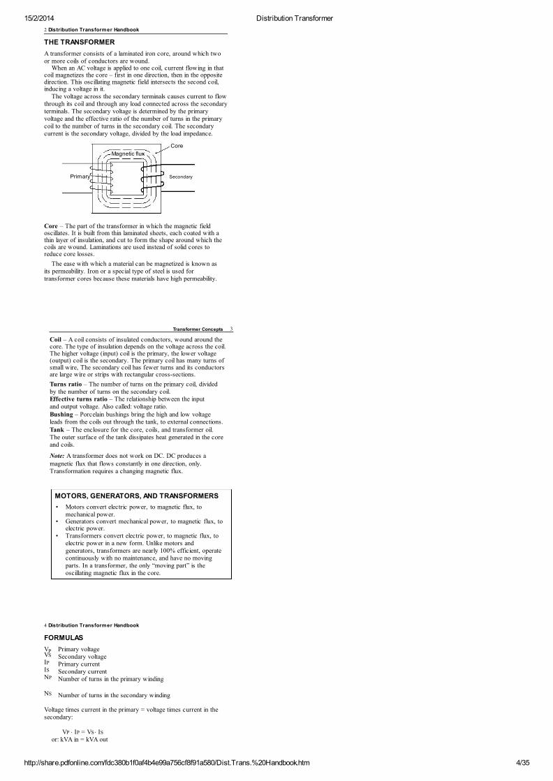
A transformer consists of a laminated iron core, around which twoor more coils of conductors are wound.
When an AC voltage is applied to one coil, current flowing in thatcoil magnetizes the core – first in one direction, then in the oppositedirection. This oscillating magnetic field intersects the second coil,inducing a voltage in it.
The voltage across the secondary terminals causes current to flowthrough its coil and through any load connected across the secondaryterminals. The secondary voltage is determined by the primaryvoltage and the effective ratio of the number of turns in the primarycoil to the number of turns in the secondary coil. The secondarycurrent is the secondary voltage, divided by the load impedance.
Core
Magnetic flux
Primary Secondary
Core – The part of the transformer in which the magnetic fieldoscillates. It is built from thin laminated sheets, each coated with athin layer of insulation, and cut to form the shape around which thecoils are wound. Laminations are used instead of solid cores toreduce core losses.
The ease with which a material can be magnetized is known asits permeability. Iron or a special type of steel is used fortransformer cores because these materials have high permeability.
Transformer Concepts 3
Coil – A coil consists of insulated conductors, wound around thecore. The type of insulation depends on the voltage across the coil.The higher voltage (input) coil is the primary, the lower voltage(output) coil is the secondary. The primary coil has many turns ofsmall wire, The secondary coil has fewer turns and its conductorsare large wire or strips with rectangular cross-sections.
Turns ratio – The number of turns on the primary coil, dividedby the number of turns on the secondary coil.Effective turns ratio – The relationship between the inputand output voltage. Also called: voltage ratio.Bushing – Porcelain bushings bring the high and low voltageleads from the coils out through the tank, to external connections.Tank – The enclosure for the core, coils, and transformer oil.The outer surface of the tank dissipates heat generated in the coreand coils.
Note: A transformer does not work on DC. DC produces amagnetic flux that flows constantly in one direction, only.Transformation requires a changing magnetic flux.
MOTORS, GENERATORS, AND TRANSFORMERS
• Motors convert electric power, to magnetic flux, tomechanical power.
• Generators convert mechanical power, to magnetic flux, toelectric power.
• Transformers convert electric power, to magnetic flux, toelectric power in a new form. Unlike motors andgenerators, transformers are nearly 100% efficient, operatecontinuously with no maintenance, and have no movingparts. In a transformer, the only “moving part” is theoscillating magnetic flux in the core.
4 Distribution Transformer Handbook
FORMULAS
V Primary voltageSecondary voltagePrimary currentSecondary currentNumber of turns in the primary winding
Number of turns in the secondary winding
Voltage times current in the primary = voltage times current in thesecondary:
PVS
IP
IS
NP
NS
VP × IP = VS × IS
or: kVA in = kVA out
15/2/2014 Distribution Transformer
http://share.pdfonline.com/fdc380b1f0af4b4e99a756cf8f91a580/Dist.Trans.%20Handbook.htm 5/35
This formula is approximate. In practice, small losses inthe transformer make kVA out slightly less than kVA in.
Voltages are proportional to the turns ratio:
V N ––= ––
Currents are inversely proportional to the turns ratio:
I N ––= ––
P P
VS NS
P S
IS NP
Transformer Concepts 5
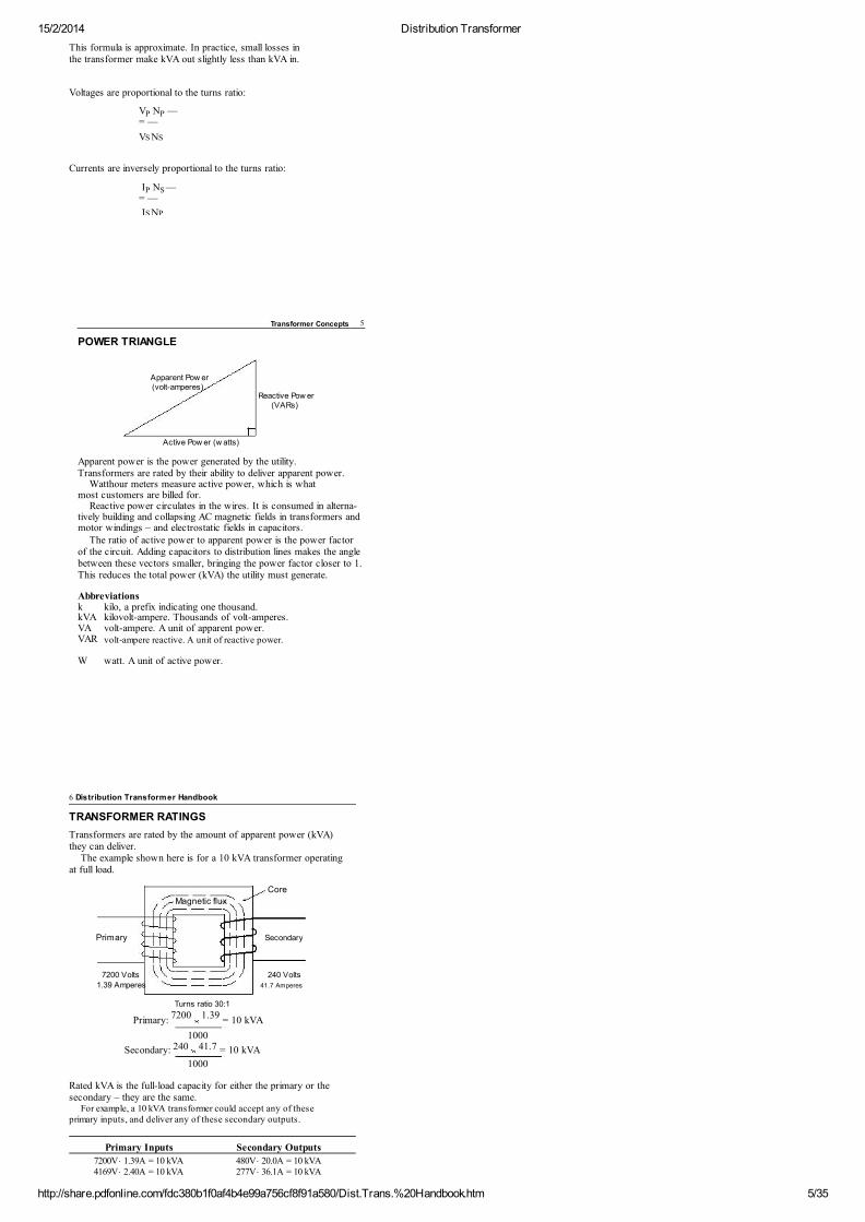
POWER TRIANGLE
Apparent Pow er(volt-amperes)
Reactive Pow er(VARs)
Active Pow er (w atts)
Apparent power is the power generated by the utility.Transformers are rated by their ability to deliver apparent power.
Watthour meters measure active power, which is whatmost customers are billed for.
Reactive power circulates in the wires. It is consumed in alterna-tively building and collapsing AC magnetic fields in transformers andmotor windings – and electrostatic fields in capacitors.
The ratio of active power to apparent power is the power factorof the circuit. Adding capacitors to distribution lines makes the anglebetween these vectors smaller, bringing the power factor closer to 1.This reduces the total power (kVA) the utility must generate.
Abbreviationsk kilo, a prefix indicating one thousand.kVA kilovolt-ampere. Thousands of volt-amperes.VA volt-ampere. A unit of apparent power.VAR volt-ampere reactive. A unit of reactive power.
W watt. A unit of active power.
6 Distribution Transformer Handbook
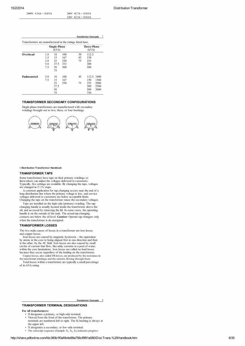
TRANSFORMER RATINGS
Transformers are rated by the amount of apparent power (kVA)they can deliver.
The example shown here is for a 10 kVA transformer operatingat full load.
Core
Magnetic flux
Primary Secondary
7200 Volts 240 Volts
1.39 Amperes 41.7 Amperes
Turns ratio 30:1
Primary: = 10 kVA
1000
Secondary: = 10 kVA
1000
Rated kVA is the full-load capacity for either the primary or thesecondary – they are the same.
For example, a 10 kVA transformer could accept any of theseprimary inputs, and deliver any of these secondary outputs.
Primary Inputs Secondary Outputs
7200V × 1.39A = 10 kVA 480V × 20.0A = 10 kVA4169V × 2.40A = 10 kVA 277V × 36.1A = 10 kVA
7200 1.39
240 41.7
15/2/2014 Distribution Transformer
http://share.pdfonline.com/fdc380b1f0af4b4e99a756cf8f91a580/Dist.Trans.%20Handbook.htm 6/35
2400V × 4.16A = 10 kVA 240V × 42.7A = 10 kVA
120V × 83.3A = 10 kVA
Transformer Concepts 7
Transformers are manufactured in the ratings listed here.
Single-Phase
Three-Phase
(kVA)
(kVA)
Overhead 1.0 10 100 30 112.5
1.5 15 167 45 150
3.0 25 250 75 225
5.0 37.5 333
300
7.5 50 500
500
75
Padmounted 5.0 10 100 45 112.5 1000
7.5 15 167
150 1500
25 250 75 225 2000
37.5
300 2500
50
500 3000
75
750
TRANSFORMER SECONDARY CONFIGURATIONS
Single-phase transformers are manufactured with secondarywindings brought out to two, three, or four bushings.
8 Distribution Transformer Handbook
TRANSFORMER TAPS
Some transformers have taps on their primary windings solineworkers can adjust the voltages delivered to customers.Typically, five settings are available. By changing the taps, voltagesare changed in 2 /2% steps.
A common application for tap-changing occurs near the end of along distribution line where the primary voltage is low, and servicevoltages delivered to customers are below acceptable limits.Changing the taps on the transformer raises the secondary voltages.
Taps are installed on the high-side (primary) winding. The tap-changing handle is usually located inside the transformer above theoil, and accessed by removing the lid. In some cases, the operatinghandle is on the outside of the tank. The actual tap-changingcontacts are below the oil level. Caution: Operate tap changers onlywhen the transformer is de-energized.
TRANSFORMER LOSSES
The two main causes of losses in a transformer are iron lossesand copper losses.
Iron losses are caused by magnetic hysteresis – the oppositionby atoms in the core to being aligned first in one direction and thenin the other, by the AC field. Iron losses are also caused by smallcircles of current that flow, like eddy currents in a pool of water,within the core laminations. Iron losses are called no-load lossesbecause they occur regardless of the loading on the transformer.
Copper losses, also called I R losses, are produced by the resistance inthe transformer windings and the currents flowing through them.
Total losses within a transformer are typically a small percentageof its kVA rating.
1
2
Transformer Concepts 9
TRANSFORMER TERMINAL DESIGNATIONS
For all transformers:• H designates a primary, or high-side terminal.• Viewed from the front of the transformer: The primary
terminals are numbered left to right. The H bushing is always atthe upper left.
• X designates a secondary, or low-side terminal.• The subscript sequence (Example: X , X , X ) indicates progress
1
1 2 3
15/2/2014 Distribution Transformer
http://share.pdfonline.com/fdc380b1f0af4b4e99a756cf8f91a580/Dist.Trans.%20Handbook.htm 7/35
along the coil windings, connected in series. The lowest andhighest numbered terminals are across the full winding.
For single-phase transformers:• Viewed from the front of the transformer: Secondary terminals
on subtractive transformers are numbered left-to-right.Secondary terminals on additive transformers are numberedright-to-left. This designation makes the phases of H and Xcoincide.Note: For details on subtractive and additive transformers,see Polarity, below.
For three-phase transformers:• Neutral terminals are designated by the subscript 0.
Examples: H , X .
POLARITY
Transformer polarity refers to the instantaneous relationship betweenthe oscillating voltage at the primary, and the oscillating voltage at thesecondary. There are two possibilities: the voltages are eitherin-phase, or 180º out-of-phase – it depends on whether the primaryand secondary windings are wound in the same direction, or inopposite directions.
Polarity is unimportant when a transformer is installed alone, butis extremely important when transformers are installed in parallel, oras a bank. If one transformer in a bank has a different polarity, theconnections to either the primary or the secondary bushings of thattransformer must be reversed.
1 1
0 0
Secondary
Voltage primary to secondary
Volts
Time
10 Distribution Transformer Handbook
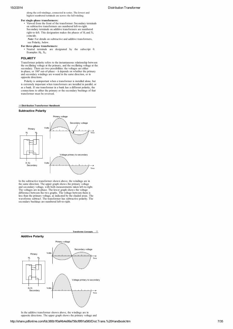
Subtractive Polarity
Primary voltage
Secondary voltage
Primary Volts
H H Time
In the subtractive transformer shown above, the windings are inthe same direction. The upper graph shows the primary voltageand secondary voltage, with both measurements taken left-to-right.The voltages are in-phase. The lower graph shows the voltagedifference between the two graphs. The voltage between them isless than the primary voltage, as indicated by the shaded areas. Thewaveforms subtract. The transformer has subtractive polarity. Thesecondary bushings are numbered left-to-right.
1 2
X1 X2
Secondary
Voltage primary to secondary
Volts
Time
Transformer Concepts 11
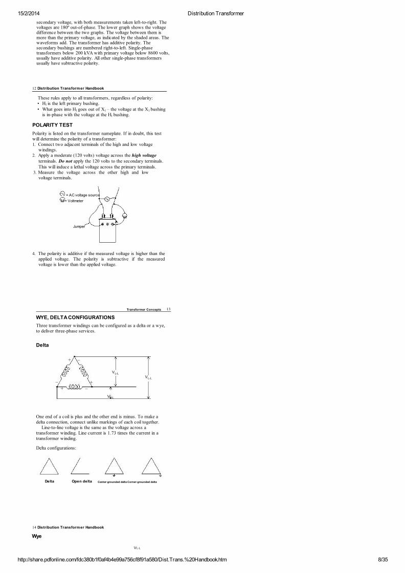
Additive Polarity
Primary voltage
Secondary voltage
Primary Volts
H H Time
In the additive transformer shown above, the windings are inopposite directions. The upper graph shows the primary voltage and
1 2
X2 X1
15/2/2014 Distribution Transformer
http://share.pdfonline.com/fdc380b1f0af4b4e99a756cf8f91a580/Dist.Trans.%20Handbook.htm 8/35
secondary voltage, with both measurements taken left-to-right. Thevoltages are 180º out-of-phase. The lower graph shows the voltagedifference between the two graphs. The voltage between them ismore than the primary voltage, as indicated by the shaded areas. Thewaveforms add. The transformer has additive polarity. Thesecondary bushings are numbered right-to-left. Single-phasetransformers below 200 kVA with primary voltage below 8600 volts,usually have additive polarity. All other single-phase transformersusually have subtractive polarity.
12 Distribution Transformer Handbook
These rules apply to all transformers, regardless of polarity:• H is the left primary bushing.• What goes into H goes out of X – the voltage at the X bushing
is in-phase with the voltage at the H bushing.
POLARITY TEST
Polarity is listed on the transformer nameplate. If in doubt, this testwill determine the polarity of a transformer:1. Connect two adjacent terminals of the high and low voltage
windings.2. Apply a moderate (120 volts) voltage across the high voltage
terminals. Do not apply the 120 volts to the secondary terminals.This will induce a lethal voltage across the primary terminals.
3. Measure the voltage across the other high and lowvoltage terminals.
= AC voltage source
M = Voltmeter
M
Jumper
4. The polarity is additive if the measured voltage is higher than theapplied voltage. The polarity is subtractive if the measuredvoltage is lower than the applied voltage.
1
1 1 1
1
Transformer Concepts 13
WYE, DELTA CONFIGURATIONS
Three transformer windings can be configured as a delta or a wye,to deliver three-phase services.
Delta
+ –
L-L
–L-L
++ –
L-L
One end of a coil is plus and the other end is minus. To make adelta connection, connect unlike markings of each coil together.
Line-to-line voltage is the same as the voltage across atransformer winding. Line current is 1.73 times the current in atransformer winding.
Delta configurations:
Delta Open delta Center-grounded delta Corner-grounded delta
V
V
V
14 Distribution Transformer Handbook
Wye
VL-L
15/2/2014 Distribution Transformer
http://share.pdfonline.com/fdc380b1f0af4b4e99a756cf8f91a580/Dist.Trans.%20Handbook.htm 9/35
+
+ VL-N VL-N
– –VL-L
N
–
VL-L
VL-N
+
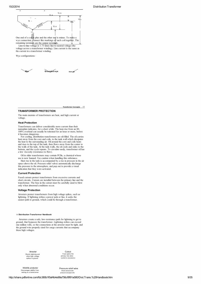
One end of a coil is plus and the other end is minus. To make awye connection, connect like markings of each coil together. Theremaining terminals are the output terminals.
Line-to-line voltage is 1.73 times line-to-neutral voltage (thevoltage across a transformer winding). Line current is the same asthe current in a transformer winding.
Wye configurations:
Wye Grounded wye Open wye
Transformer Concepts 15
TRANSFORMER PROTECTION
The main enemies of transformers are heat, and high current orvoltage.
Heat Protection
Transformers can deliver considerably more current than theirnameplate indicates, for a short while. The heat-rise from an 80-100% overload can usually be tolerated for an hour or more, beforeit becomes dangerous.
For cooling, distribution transformers are oil-filled. The oil carriesheat away from the core and coils, to the tank wall which dissipatesthe heat to the surrounding air. Oil around the core and coils heatsand rises to the top of the tank, then flows away from the center tothe walls of the tank. At the tank walls, the oil cools and sinks to thebottom, and the cycle repeats. To circulate easily, transformer oil hasa low viscosity (resistance to flow).
Oil in older transformers may contain PCBs, a chemical whoseuse is now banned. Use caution when handling this substance.
Heat rise in the tank is accompanied by a rise in pressure in the airspace above the oil. Pressure relief valves automatically dischargethis pressure to the atmosphere, and pop out to provide a visualindication that they were activated.
Current Protection
Fused cutouts protect transformers from excessive currents andshort circuits. Cutouts are installed between the primary line and thetransformer. The fuse in the cutout must be carefully sized to blowonly when abnormal conditions occur.
Voltage Protection
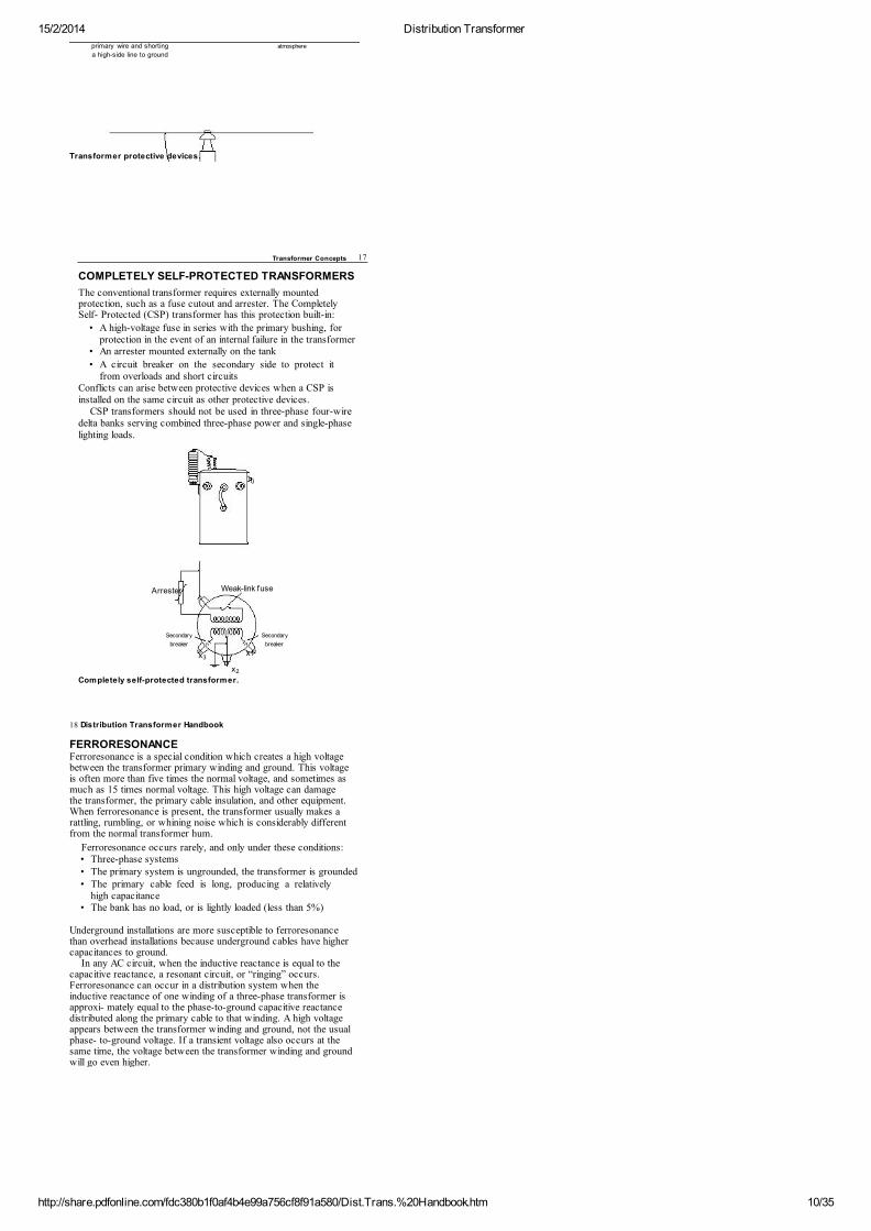
Arresters protect transformers from high voltage spikes, such aslightning. If lightning strikes a power pole or line, it seeks theeasiest path to ground, which could be through a transformer.
ArresterShunts lightning and
other high v oltage
spikes to ground
Wildlife protectorDiscourages wildlif e f rom
resting on a transf ormer
CutoutFuse opens the
primary line when
current is excessiv e
Pressure relief valveAllows excessive tank
pressure to escape to the
16 Distribution Transformer Handbook
Arresters create a safe, low-resistance path for lightning to get toground, that bypasses the transformer. Lightning strikes can exceedone million volts, so the connections at the arrester must be tight, andthe ground wire properly sized for surge currents that accompanythese high voltages.
15/2/2014 Distribution Transformer
http://share.pdfonline.com/fdc380b1f0af4b4e99a756cf8f91a580/Dist.Trans.%20Handbook.htm 10/35
primary wire and shorting
a high-side line to ground
atmosphere
Transformer protective devices.
Transformer Concepts 17
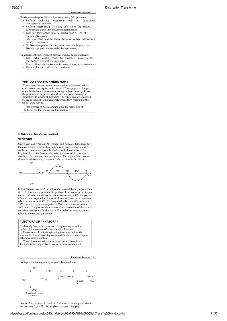
COMPLETELY SELF-PROTECTED TRANSFORMERS
The conventional transformer requires externally mountedprotection, such as a fuse cutout and arrester. The CompletelySelf- Protected (CSP) transformer has this protection built-in:
• A high-voltage fuse in series with the primary bushing, forprotection in the event of an internal failure in the transformer
• An arrester mounted externally on the tank
• A circuit breaker on the secondary side to protect itfrom overloads and short circuits
Conflicts can arise between protective devices when a CSP isinstalled on the same circuit as other protective devices.
CSP transformers should not be used in three-phase four-wiredelta banks serving combined three-phase power and single-phaselighting loads.
Arrester Weak-link fuse
Secondary Secondary
breaker breaker
x
x
Completely self-protected transformer.
3x1
2
18 Distribution Transformer Handbook
FERRORESONANCEFerroresonance is a special condition which creates a high voltagebetween the transformer primary winding and ground. This voltageis often more than five times the normal voltage, and sometimes asmuch as 15 times normal voltage. This high voltage can damagethe transformer, the primary cable insulation, and other equipment.When ferroresonance is present, the transformer usually makes arattling, rumbling, or whining noise which is considerably differentfrom the normal transformer hum.
Ferroresonance occurs rarely, and only under these conditions:• Three-phase systems• The primary system is ungrounded, the transformer is grounded• The primary cable feed is long, producing a relatively
high capacitance• The bank has no load, or is lightly loaded (less than 5%)
Underground installations are more susceptible to ferroresonancethan overhead installations because underground cables have highercapacitances to ground.
In any AC circuit, when the inductive reactance is equal to thecapacitive reactance, a resonant circuit, or “ringing” occurs.Ferroresonance can occur in a distribution system when theinductive reactance of one winding of a three-phase transformer isapproxi- mately equal to the phase-to-ground capacitive reactancedistributed along the primary cable to that winding. A high voltageappears between the transformer winding and ground, not the usualphase- to-ground voltage. If a transient voltage also occurs at thesame time, the voltage between the transformer winding and groundwill go even higher.
15/2/2014 Distribution Transformer
http://share.pdfonline.com/fdc380b1f0af4b4e99a756cf8f91a580/Dist.Trans.%20Handbook.htm 11/35
Transformer Concepts 19
To decrease the possibility of ferroresonance, field personnel:• Perform switching operations only at three-phase
gang-operated switches• Perform single-phase switching only when the primary
cable length is less than maximum design limits• Load the transformer bank to greater than 5-10% of
the nameplate rating• Add a resistive load to lower the peak voltage that occurs
during ferroresonance• On floating-wye closed-delta banks, temporarily ground the
floating wye point during switching operations.
To decrease the possibility of ferroresonance, design engineers:• Keep cable lengths from the switching point to the
transformer well within design limits• Convert three-phase closed delta banks to wye-wye connections• Use a triplex core cable to the transformer
WHY DO TRANSFORMERS HUM?
When a transformer core is magnetized and demagnetized, itscore laminations expand and contract. These physical changesto the laminations happen twice during each 60 hertz cycle, onthe positive and negative sides of the flux cycle, causing thelaminations to vibrate at 120 hertz. The vibrations are conveyedby the cooling oil to the tank wall, where they escape into theair as sound waves.
Transformer hum also occurs at higher harmonics of120 hertz, but these tones are less audible.
20 Distribution Transformer Handbook
VECTORS
Sine waves can represent AC voltages and currents, but except forthe most simple circuits, they make circuit analysis messy andconfusing. Vectors are usually used instead of sine waves. Thelength of the vector (arrow) illustrates the value of the electricalquantity – for example, how many volts. The angle of each vectorshows its relation- ship, relative to other vectors in the circuit.
90° A
180° A
0° 90° 180° 270° 0° 0°
Time
270°
In this diagram, vector A, which rotates around the origin, is shownat 0°. At this starting position, the portion of the vector projected onthe vertical axis, is zero. As the vector rotates up to 90°, the portionof the vector projected on the vertical axis increases, to a maximumwhen the vector is at 90°. The projected value then falls to zero at180°, become maximum negative at 270°, and returns to zero at360° or 0°. The process then repeats. Each revolution of the vectordescribes one cycle of a sine wave. For 60 hertz systems, vectorsmake 60 revolutions per second.
“VECTOR” OR “PHASOR”?
Technically, vector is a mechanical engineering term thatdefines the magnitude of a force and its direction.
Phasor is an electrical engineering term that defines themagnitude of an electrical quantity and its phase relationship toother electrical quantities.
While phasor would seem to be the correct term to usefor transformer applications, vector is more widely used.
Transformer Concepts 21
Voltages in a three-phase system are illustrated here:
90°
Volts
A
B
C
C
A
1 cycle 1cycle
1 cycle
180° 0°4 2
3
cycle Time
4
B
270°
Snapshot of v oltages
at Time = 0
Vector A is shown at 0°, and the A sine wave on the graph startsby crossing 0, just like the graph on the preceding page.
15/2/2014 Distribution Transformer
http://share.pdfonline.com/fdc380b1f0af4b4e99a756cf8f91a580/Dist.Trans.%20Handbook.htm 12/35
Vector B starts at 240° and initially projects a negative value onthe vertical axis. The B sine wave on the graph also starts at anegative value.
Vector C starts at 120°. Its sine wave has passed maximumvalue, and is heading for zero.
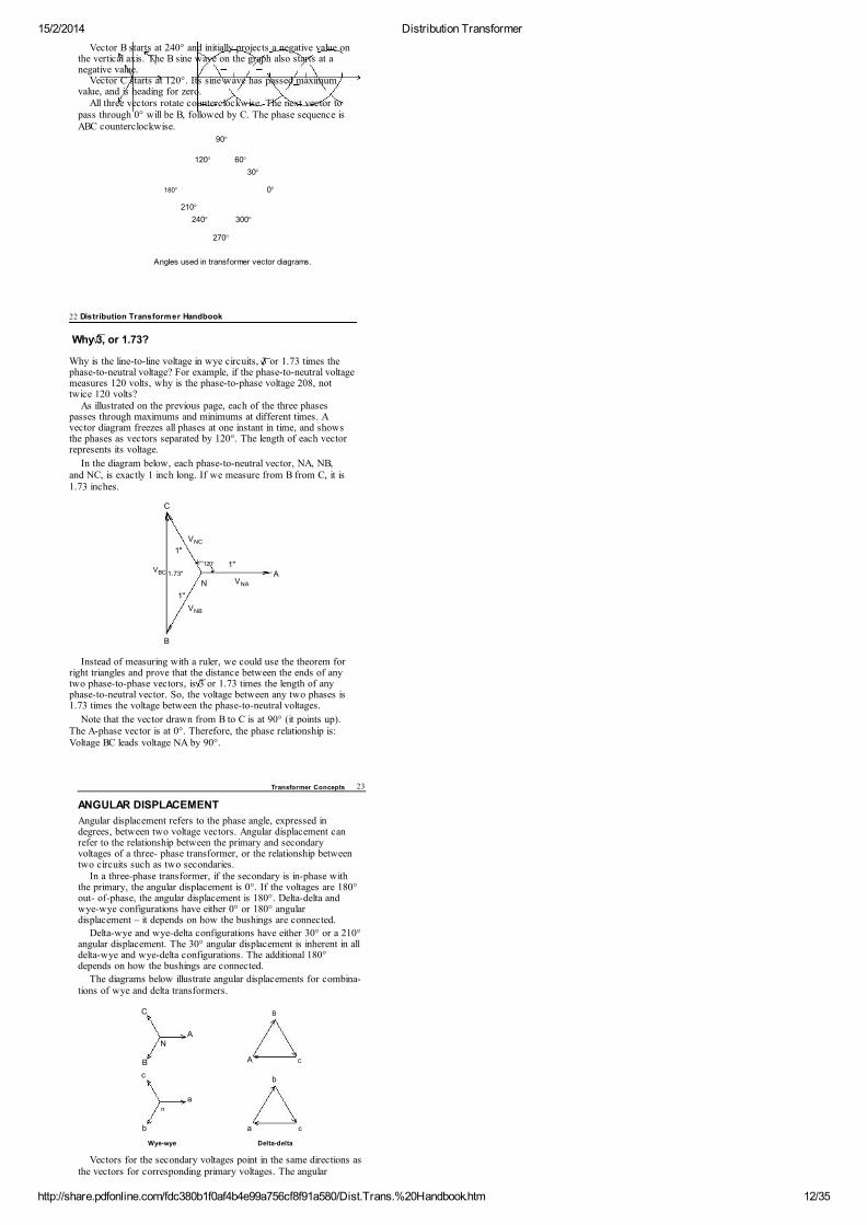
All three vectors rotate counterclockwise. The next vector topass through 0° will be B, followed by C. The phase sequence isABC counterclockwise.
90°
120° 60°
30°
180° 0°
210°
240° 300°
270°
Angles used in transformer vector diagrams.
22 Distribution Transformer Handbook
Why 3, or 1.73?
Why is the line-to-line voltage in wye circuits, 3 or 1.73 times thephase-to-neutral voltage? For example, if the phase-to-neutral voltagemeasures 120 volts, why is the phase-to-phase voltage 208, nottwice 120 volts?
As illustrated on the previous page, each of the three phasespasses through maximums and minimums at different times. Avector diagram freezes all phases at one instant in time, and showsthe phases as vectors separated by 120°. The length of each vectorrepresents its voltage.
In the diagram below, each phase-to-neutral vector, NA, NB,and NC, is exactly 1 inch long. If we measure from B from C, it is1.73 inches.
C
NC
1"
120° 1"BC
1.73" A
N NA
1"
NB
B
Instead of measuring with a ruler, we could use the theorem forright triangles and prove that the distance between the ends of anytwo phase-to-phase vectors, is 3 or 1.73 times the length of anyphase-to-neutral vector. So, the voltage between any two phases is1.73 times the voltage between the phase-to-neutral voltages.
Note that the vector drawn from B to C is at 90° (it points up).The A-phase vector is at 0°. Therefore, the phase relationship is:Voltage BC leads voltage NA by 90°.
V
V
V
V
Transformer Concepts 23
ANGULAR DISPLACEMENT
Angular displacement refers to the phase angle, expressed indegrees, between two voltage vectors. Angular displacement canrefer to the relationship between the primary and secondaryvoltages of a three- phase transformer, or the relationship betweentwo circuits such as two secondaries.
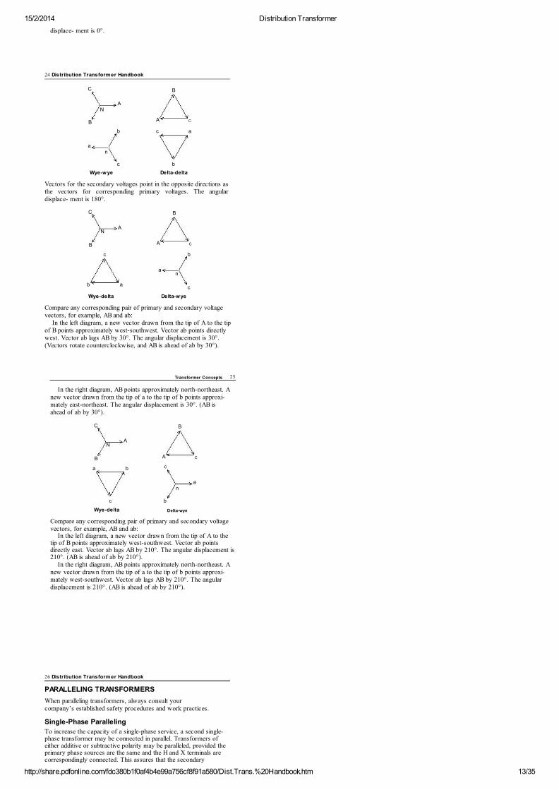
In a three-phase transformer, if the secondary is in-phase withthe primary, the angular displacement is 0°. If the voltages are 180°out- of-phase, the angular displacement is 180°. Delta-delta andwye-wye configurations have either 0° or 180° angulardisplacement – it depends on how the bushings are connected.
Delta-wye and wye-delta configurations have either 30° or a 210°angular displacement. The 30° angular displacement is inherent in alldelta-wye and wye-delta configurations. The additional 180°depends on how the bushings are connected.
The diagrams below illustrate angular displacements for combina-tions of wye and delta transformers.
C
B
A
N
B A C
c b
a
n
b a c
Wye-wye Delta-delta
Vectors for the secondary voltages point in the same directions asthe vectors for corresponding primary voltages. The angular
15/2/2014 Distribution Transformer
http://share.pdfonline.com/fdc380b1f0af4b4e99a756cf8f91a580/Dist.Trans.%20Handbook.htm 13/35
displace- ment is 0°.
24 Distribution Transformer Handbook
C B
A
N
B A C
b c a
a
n
c
b
Wye-wye
Delta-delta
Vectors for the secondary voltages point in the opposite directions asthe vectors for corresponding primary voltages. The angulardisplace- ment is 180°.
C
B
NA
B A C
c
b
an
b ac
Wye-delta
Delta-wye
Compare any corresponding pair of primary and secondary voltagevectors, for example, AB and ab:
In the left diagram, a new vector drawn from the tip of A to the tipof B points approximately west-southwest. Vector ab points directlywest. Vector ab lags AB by 30°. The angular displacement is 30°.(Vectors rotate counterclockwise, and AB is ahead of ab by 30°).
Transformer Concepts 25
In the right diagram, AB points approximately north-northeast. Anew vector drawn from the tip of a to the tip of b points approxi-mately east-northeast. The angular displacement is 30°. (AB isahead of ab by 30°).
C
B
NA
B
A C
a b c
a n
c
b
Wye-delta
Delta-wye
Compare any corresponding pair of primary and secondary voltagevectors, for example, AB and ab:
In the left diagram, a new vector drawn from the tip of A to thetip of B points approximately west-southwest. Vector ab pointsdirectly east. Vector ab lags AB by 210°. The angular displacement is210°. (AB is ahead of ab by 210°).
In the right diagram, AB points approximately north-northeast. Anew vector drawn from the tip of a to the tip of b points approxi-mately west-southwest. Vector ab lags AB by 210°. The angulardisplacement is 210°. (AB is ahead of ab by 210°).
26 Distribution Transformer Handbook
PARALLELING TRANSFORMERS
When paralleling transformers, always consult yourcompany’s established safety procedures and work practices.
Single-Phase Paralleling
To increase the capacity of a single-phase service, a second single-phase transformer may be connected in parallel. Transformers ofeither additive or subtractive polarity may be paralleled, provided theprimary phase sources are the same and the H and X terminals arecorrespondingly connected. This assures that the secondary
15/2/2014 Distribution Transformer
http://share.pdfonline.com/fdc380b1f0af4b4e99a756cf8f91a580/Dist.Trans.%20Handbook.htm 14/35
voltages are in-phase.
When single-phase transformers are paralleled, thetransformers must meet these conditions:
• Voltage ratings are identical• Tap settings are identical• Percent impedances are very nearly the same
Three-Phase Paralleling
Occasionally, three-phase transformer banks areparalleled. This additional condition must be met:• The voltages on the secondary terminals must be in-phase. One
way to determine if the angular displacements match, is to takevoltage readings between corresponding pairs of bushings. Fordetails on paralleling three-phase transformers, see pages 57-61.
A wye-wye bank can be paralleled with another wye-wye bank orwith a delta-delta bank. These transformers can be wired to havethe same angular displacements (either 0º or 180º).
A wye-delta bank can be paralleled with another wye-delta bank orwith a delta-wye bank. These transformers can be wired to have thesame angular displacement (either 30º or 210º).
A wye-wye bank and a delta-delta bank cannot be paralleleddirectly with a wye-delta bank or a delta-wye bank.
Transformer Connections 27
CHAPTER
2TRANSFORMER CONNECTIONS
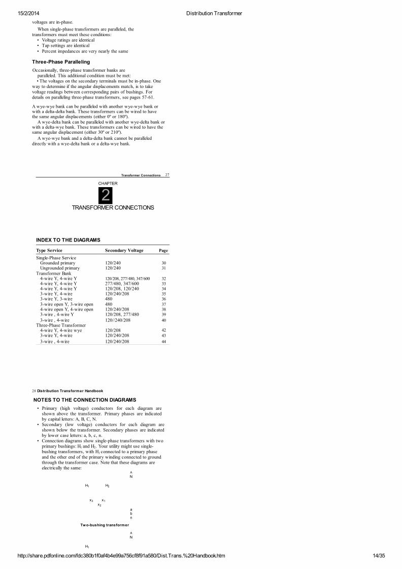
INDEX TO THE DIAGRAMS
Type Service Secondary Voltage Page
Single-Phase Service
Grounded primary 120/240 30Ungrounded primary 120/240 31
Transformer Bank
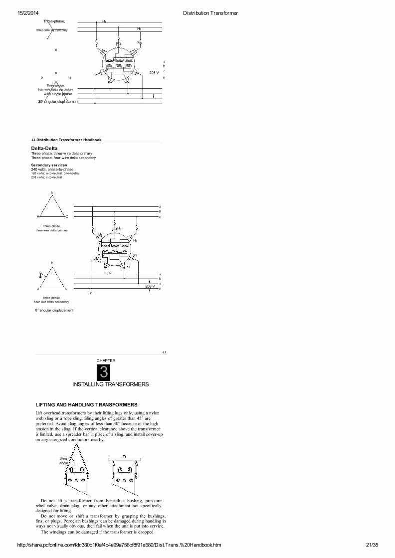
4-wire Y, 4-wire Y 120/208, 277/480, 347/600 324-wire Y, 4-wire Y 277/480, 347/600 334-wire Y, 4-wire Y 120/208, 120/240 343-wire Y, 4-wire 120/240/208 353-wire Y, 3-wire 480 363-wire open Y, 3-wire open 480 374-wire open Y, 4-wire open 120/240/208 383-wire , 4-wire Y 120/208, 277/480 39
3-wire , 4-wire 120//240/208 40Three-Phase Transformer
4-wire Y, 4-wire wye 120/208 423-wire Y, 4-wire 120/240/208 43
3-wire , 4-wire 120/240/208 44
28 Distribution Transformer Handbook
NOTES TO THE CONNECTION DIAGRAMS
• Primary (high voltage) conductors for each diagram areshown above the transformer. Primary phases are indicatedby capital letters: A, B, C, N.
• Secondary (low voltage) conductors for each diagram areshown below the transformer. Secondary phases are indicatedby lower case letters: a, b, c, n.
• Connection diagrams show single-phase transformers with twoprimary bushings: H and H . Your utility might use single-bushing transformers, with H connected to a primary phaseand the other end of the primary winding connected to groundthrough the transformer case. Note that these diagrams areelectrically the same:
A
N
H H
x x
x
a b
n
Two-bushing transformer
A
N
H
1 2
1
1 2
3 1
2
1
15/2/2014 Distribution Transformer
http://share.pdfonline.com/fdc380b1f0af4b4e99a756cf8f91a580/Dist.Trans.%20Handbook.htm 15/35
x
a
b
n
Single-bushing transformer
3 x2 x1
Transformer Connections 29
• The transformers shown in the diagrams are additive polarity.If a subtractive transformer is used instead, make connectionsto the same terminal numbers marked in the diagrams. Thesecondary terminals will be physically located on thetransformer tank in the opposite sequence from that shown inthe diagrams.
• The secondary voltages shown are the voltages eachcircuit typically delivers. Other outputs are possible,depending the primary voltage and transformers used.
• When two-bushing transformers are used in single-phasecircuits, normally H is connected to the primary and H toground. However, if there is a clearance problem (treesoverhead, restricted climbing space, etc.), for convenience,H may be connected to ground and H to the primary.
• Transformer cases are shown grounded. This practice isnot followed by all utilities. Always follow all yourcompany’s established operating and safety procedures.
• For three-phase diagrams:- Phase sequence is ABC.- Phases rotate counterclockwise.- Secondary voltages are labeled with a minus sign (-a, -b,
and -c) when the angular displacement for the configurationis 180º, or is 180º plus the 30º angular displacement inherentin all wye-delta and delta-wye configurations.
The diagrams in this handbook illustrate the most popular configura-tions. Many others are possible. If another configuration is used byyour utility, you might sketch it for reference on a blank page at theback of the book.
Note: Send a copy of your sketch to us and we will return to youa computer-precise illustration, ready to paste in your handbook.
1 2
1 2
30 Distribution Transformer Handbook
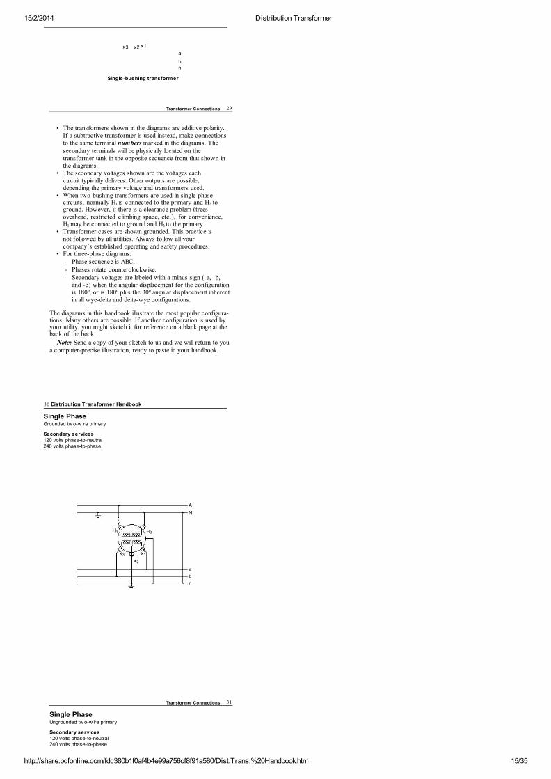
Single PhaseGrounded tw o-w ire primary
Secondary services120 volts phase-to-neutral240 volts phase-to-phase
A
N
H H
x x
x
a
b
n
1 2
3 1
2
Transformer Connections 31
Single PhaseUngrounded tw o-w ire primary
Secondary services120 volts phase-to-neutral240 volts phase-to-phase
15/2/2014 Distribution Transformer
http://share.pdfonline.com/fdc380b1f0af4b4e99a756cf8f91a580/Dist.Trans.%20Handbook.htm 16/35
A B
H H
x x
x
a
b
n
1 2
3 1
2
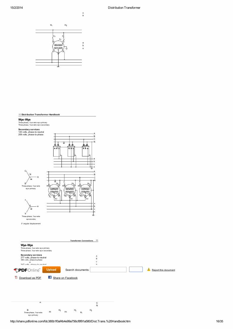
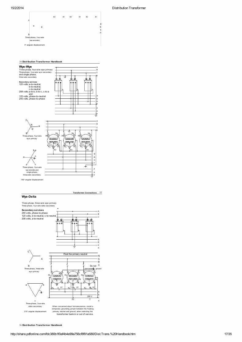
Wye-WyeThree-phase, f our-wire wy e primary
Three-phase, f our-wire wy e secondary
Secondary services120 volts, phase-to-neutral208 volts, phase-to-phase
C
N
A
A
B
C
N
a
b
c
n
A
B
C
N
32 Distribution Transformer Handbook
B
HH
HH
HH
Three-phase, f our-wire
wy e primary
x
c
n
a
a
b
c
b
n
Three-phase, f our-wire
wye secondary
0° angular displacement
1
2
1
2
1
2
3x1 x3 x1 x3 x1
x2 x2 x2
Wye-WyeThree-phase, f our-wire wy e primary
Three-phase, f our-wire wy e secondary
Secondary services277 volts, phase-to-neutral480 v olts, phase-to-phase
or
347 volts, phase-to-neutral600 volts, phase-to-phase
A
B
C
N
a
b
c
n
Transformer Connections 33
C A
NA
B
C
N
B
H HH
HThree-phase, f our-wire
wy e primary
H12
H12
1
2
Search documents: Report this document
Download as PDF Share on Facebook
15/2/2014 Distribution Transformer
http://share.pdfonline.com/fdc380b1f0af4b4e99a756cf8f91a580/Dist.Trans.%20Handbook.htm 17/35
c
n
a
a
b
c
b
n
Three-phase, f our-wire
wye secondary
0° angular displacement
x2 x1 x2 x1 x2 x1
34 Distribution Transformer Handbook
Wye-Wye
A
Three-phase, four-wire wye primary
B
Three-phase, f our-wire wy e secondary ,
C
and single phase, N
three-wire secondary
Secondary services
120 volts:a-to-neutral,
b-to-neutral,
c-to-neutral
208 volts:a-to-b, b-to-c, c-to-a
and
-a120 volts, phase-to-neutral
-b240 volts, phase-to-phase
-c
n
p
p
n
C A
NA
B
C
N
B
HH
HH
HH
Three-phase, f our-wire
wy e primary
x x x x x x
b,p
n
-a
a -b
-c
p c
n
Three-phase, f our-wire p
wye secondary and
psingle-phase,
three-wire secondary
n
180° angular displacement
1
2
1
2
1
2
3 1 3 1 3 1
x2 x2 x2
Transformer Connections 35
Wye-Delta
Three-phase, three-wire wye primary
Three-phase, f our-wire delta secondary
Secondary services A
240 volts, phase-to-phase
B120 volts, b-to-neutral, c-to-neutral
C208 volts, a-to-neutral
a b
c
n
C
Float the primary neutral
N
A
A
B
B Do not C
Three-phase, three-wire permanently ground
wy e primary
H
H
H
H
a b
x
x
x
x x x
2 2
n a
b
208 V
c
c
nThree-phase, f our-wire
delta secondary When concerned about f erroresonance, install a
210° angular displacement
temporary grounding jumper between the f loating
primary neutral and ground, when switching the
transformer bank in or out of service.
21 1 1
H2H2
3x1
3x1
3x1
2
36 Distribution Transformer Handbook
15/2/2014 Distribution Transformer
http://share.pdfonline.com/fdc380b1f0af4b4e99a756cf8f91a580/Dist.Trans.%20Handbook.htm 18/35
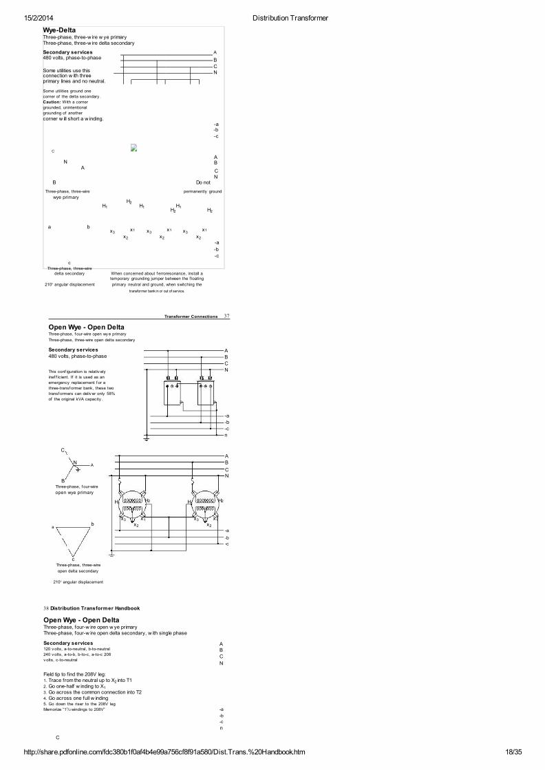
Wye-DeltaThree-phase, three-w ire w ye primaryThree-phase, three-w ire delta secondary
Secondary services
A480 volts, phase-to-phase
B
CSome utilities use this
Nconnection w ith three
primary lines and no neutral.
Some utilities ground one
corner of the delta secondary .
Caution: With a corner
grounded, unintentional
grounding of another
corner w ill short a w inding.
-a
-b
-c
C
N
A
B
A C
N
B
Do not
Three-phase, three-wire
permanently ground
wye primary
H
H
H
H
H H
a bx x x
x
x
x
-a
-b
-c
c
Three-phase, three-wireWhen concerned about f erroresonance, install a
delta secondary
temporary grounding jumper between the f loating
210° angular displacement primary neutral and ground, when switching the
transformer bank in or out of service.
21 1 1
2 2
3x1
3x1
3x1
2 2 2
Open Wye - Open DeltaThree-phase, f our-wire open wy e primary
Three-phase, three-wire open delta secondary
Secondary services
480 volts, phase-to-phase
This conf iguration is relativ ely
inef f icient. If it is used as an
emergency replacement f or a
three-transf ormer bank, these two
transf ormers can deliv er only 58%
of the original kVA capacity .
C
A
B
C
N
-a
-b
-c
n
Transformer Connections 37
N
A
A
B
C
B
N
Three-phase, f our-wire
open wye primary
H H
bx x x x
a x x
-a
-b -c
c
Three-phase, three-wire
open delta secondary
210° angular displacement
1H2
1H2
3 1 3 1
2 2
Secondary services120 v olts, a-to-neutral, b-to-neutral
240 v olts, a-to-b, b-to-c, a-to-c 208
v olts, c-to-neutral
Field tip to f ind the 208V leg:1. Trace from the neutral up to X into T12. Go one-half w inding to X3. Go across the common connection into T24. Go across one full w inding5. Go down the riser to the 208V leg
Memorize “1 /2 windings to 208V”
C
AB
C
N
-a
-b
-c
n
38 Distribution Transformer Handbook
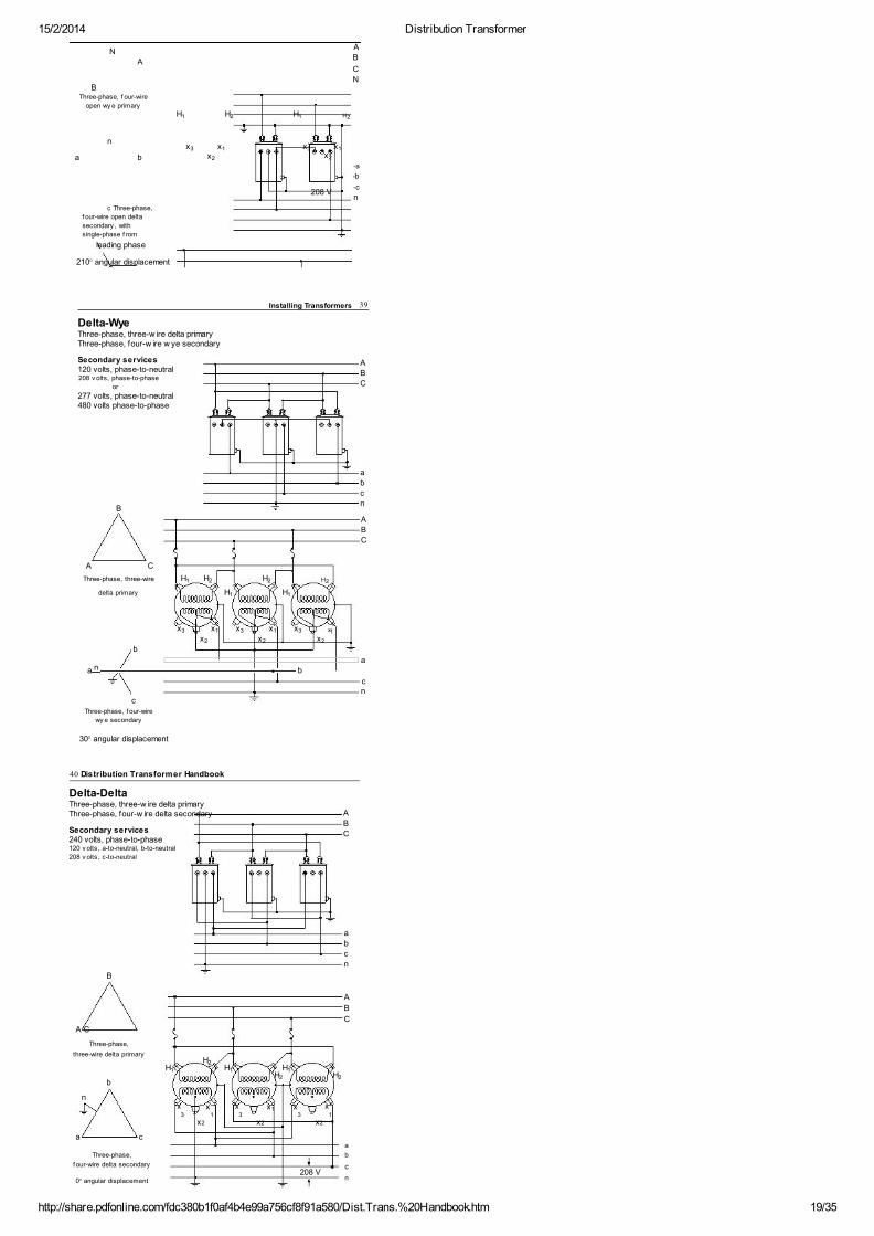
Open Wye - Open DeltaThree-phase, four-w ire open w ye primaryThree-phase, four-w ire open delta secondary, w ith single phase
2
1
1
15/2/2014 Distribution Transformer
http://share.pdfonline.com/fdc380b1f0af4b4e99a756cf8f91a580/Dist.Trans.%20Handbook.htm 19/35
N
A
BThree-phase, f our-wire
open wy e primary
n
a b
c Three-phase,
f our-wire open delta
secondary , with
single-phase f rom
leading phase
A
B
C
N
H H H H
x x xx
x x
-a
-b
208 V-c
n
210° angular displacement
1 2 1 2
3 1 3
2
1
2
Delta-WyeThree-phase, three-w ire delta primaryThree-phase, four-w ire w ye secondary
Secondary services120 volts, phase-to-neutral208 v olts, phase-to-phase
or
277 volts, phase-to-neutral480 volts phase-to-phase
B
A C
Three-phase, three-wire H H H H
delta primary
H H
A
B
C
a
b
c
n
A
B
C
Installing Transformers 39
x
x
x x
x
x x x
x
b
a
a b
cn
c
Three-phase, f our-wire
wy e secondary
30° angular displacement
1 2 2 2
1 1
3
2
1 3
2
1 3 1
2
n
Delta-DeltaThree-phase, three-w ire delta primaryThree-phase, four-w ire delta secondary
Secondary services240 volts, phase-to-phase120 v olts, a-to-neutral, b-to-neutral
208 v olts, c-to-neutral
B
A C
A
B
C
a
b
c
n
A
B
C
40 Distribution Transformer Handbook
Three-phase,
three-wire delta primary
H
H
H
H
H
H
b
n
x3
x1
x3
x x x1 3
a c
a
Three-phase,
b
f our-wire delta secondary
208 V
c
0° angular displacement
n
21 1 1
2 2
1
x2 x2 x2
15/2/2014 Distribution Transformer
http://share.pdfonline.com/fdc380b1f0af4b4e99a756cf8f91a580/Dist.Trans.%20Handbook.htm 20/35
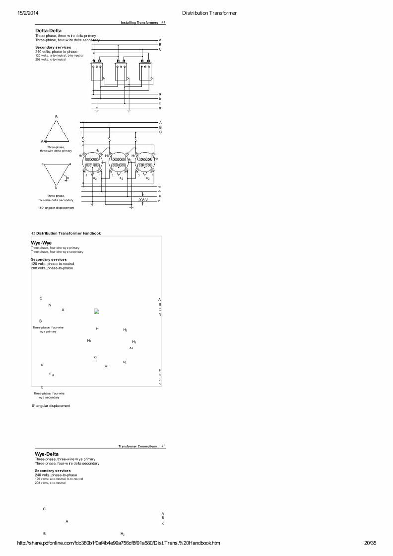
Delta-DeltaThree-phase, three-w ire delta primaryThree-phase, four-w ire delta secondary
Secondary services240 volts, phase-to-phase120 v olts, a-to-neutral, b-to-neutral
208 v olts, c-to-neutral
B
A C
A
B
C
a
b
c
n
A
B
C
Installing Transformers 41
Three-phase,
H
three-wire delta primary
H
c a
x3
x1
x
3
x x
x1
n x
x3
x
b
-a
-b
Three-phase,
208 V
-c
f our-wire delta secondary
n
180° angular displacement
2
H1 H1H1
2H2
1
2 2 2
C
N
A
B
Three-phase, f our-wire
wy e primary
c
n
b
Three-phase, f our-wire
wy e secondary
0° angular displacement
A
B
C
N
H
H
xx
x
a
b
c
n
42 Distribution Transformer Handbook
Wye-WyeThree-phase, f our-wire wy e primary
Three-phase, f our-wire wy e secondary
Secondary services120 volts, phase-to-neutral208 volts, phase-to-phase
a
H12
H03
x3
0
2
1
Transformer Connections 43
Wye-DeltaThree-phase, three-w ire w ye primaryThree-phase, four-w ire delta secondary
Secondary services240 volts, phase-to-phase120 v olts: a-to-neutral, b-to-neutral
208 v olts, c-to-neutral
C
AB
A C
B
H
2
15/2/2014 Distribution Transformer
http://share.pdfonline.com/fdc380b1f0af4b4e99a756cf8f91a580/Dist.Trans.%20Handbook.htm 21/35
Three-phase,
H
three-wire wy e primary
x
c
x
x
xa
b
n 208 V c
a nb
Three-phase,
f our-wire delta secondary
w ith single phase
30° angular displacement
1
H3
3
4
2
1
44 Distribution Transformer Handbook
Delta-DeltaThree-phase, three-w ire delta primaryThree-phase, four-w ire delta secondary
Secondary services240 volts, phase-to-phase120 v olts: a-to-neutral, b-to-neutral
208 v olts, c-to-neutral
B
A
B
A C
C
Three-phase,H
three-wire delta primary
H
H
b
n
x
xa
b
208 Vc
a c n
Three-phase,
f our-wire delta secondary
0° angular displacement
2
1
3
x3
x4
2
1
45
CHAPTER
3INSTALLING TRANSFORMERS
LIFTING AND HANDLING TRANSFORMERS
Lift overhead transformers by their lifting lugs only, using a nylonweb sling or a rope sling. Sling angles of greater than 45° arepreferred. Avoid sling angles of less than 30° because of the hightension in the sling. If the vertical clearance above the transformeris limited, use a spreader bar in place of a sling, and install cover-upon any energized conductors nearby.
Sling
angle
Do not lift a transformer from beneath a bushing, pressurerelief valve, drain plug, or any other attachment not specificallydesigned for lifting.
Do not move or shift a transformer by grasping the bushings,fins, or plugs. Porcelain bushings can be damaged during handling inways not visually obvious, then fail when the unit is put into service.
The windings can be damaged if the transformer is dropped
15/2/2014 Distribution Transformer
http://share.pdfonline.com/fdc380b1f0af4b4e99a756cf8f91a580/Dist.Trans.%20Handbook.htm 22/35
or severely jolted.When handling a transformer, take care to not damage the tank
finish. Paint scratches can lead to rust.
6
7
8
H V TA P P O S I T I O N
100% 1 OR A
97.5% 2 OR B
95% 3 OR C
92.5% 4 OR D
90% 5 OR E
H
H
SW
C
B C B
A
x
D A
D
x x x
1 H 7 2 0 0 / 1 2 4 7 0 Y
V
5
2
L
CUST
K
V
V
1 2 0 / 2 4 0 CP123456790 A
M
S
000000556
– NON- PCB MINERAL OIL –
F E WHEN MANUFACTURED CONTAINED
3
G CP R
LESS THAN 1PPM PCB
4
HV AL 95 BIL TK 10 60 HZ A D D P O L . %IZ GAL 11 W T 2 0 2 L B
LV AL 95 BIL MS CLASS OA 65° C RISE
85° C M F G D AT E A U G 9 8
5 C
E 211072 05W5
A
T
NOTES: READ INSTALLATION AND OPERATION INSTRUCTIONS S201-10-1
9
10
11
12
13
14
46 Distribution Transformer Handbook
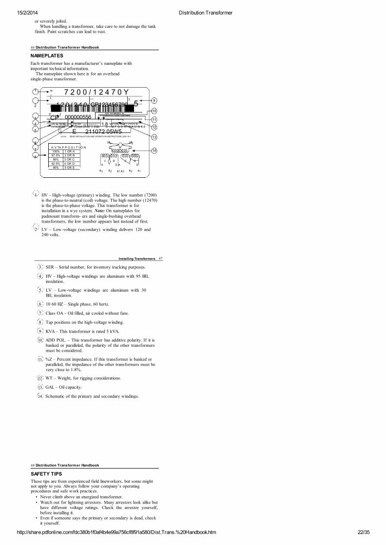
NAMEPLATES
Each transformer has a manufacturer’s nameplate withimportant technical information.
The nameplate shown here is for an overheadsingle-phase transformer.
1 HV – High-voltage (primary) winding. The low number (7200)is the phase-to-neutral (coil) voltage. The high number (12470)is the phase-to-phase voltage. This transformer is forinstallation in a wye system. Note: On nameplates forpadmount transform- ers and single-bushing overheadtransformers, the low number appears last instead of first.
2 LV – Low-voltage (secondary) winding delivers 120 and240 volts.
I.D.
1.8
1 2
2
I
3 x1 x3 2 1
Installing Transformers 47
3 SER – Serial number, for inventory tracking purposes.
4 HV – High-voltage windings are aluminum with 95 BILinsulation.
5 LV – Low-voltage windings are aluminum with 30BIL insulation.
6 10 60 HZ – Single phase, 60 hertz.
7 Class OA – Oil filled, air cooled without fans.
8 Tap positions on the high-voltage winding.
9 KVA – This transformer is rated 5 kVA.
10 ADD POL. – This transformer has additive polarity. If it isbanked or paralleled, the polarity of the other transformersmust be considered.
11 %Z – Percent impedance. If this transformer is banked orparalleled, the impedance of the other transformers must bevery close to 1.8%.
12 WT – Weight, for rigging considerations.
13 GAL – Oil capacity.
14 Schematic of the primary and secondary windings.
48 Distribution Transformer Handbook
SAFETY TIPS
These tips are from experienced field lineworkers, but some mightnot apply to you. Always follow your company’s operatingprocedures and safe work practices.
• Never climb above an energized transformer.• Watch out for lightning arrestors. Many arrestors look alike but
have different voltage ratings. Check the arrestor yourself,before installing it.
• Even if someone says the primary or secondary is dead, checkit yourself.

15/2/2014 Distribution Transformer
http://share.pdfonline.com/fdc380b1f0af4b4e99a756cf8f91a580/Dist.Trans.%20Handbook.htm 23/35
• Don’t use the transformer bracket or bolts to supportservices. Keep supports separate, for future maintenance.
• Some transformers have two tank grounds: a ground strapfrom the center bushing of the secondary, and a tank ground tothe pole ground wire.
• Use only copper wire on bolt-type transformer lugs. Aluminumwire is soft, and can flow under bolted connections and comeloose. Aluminum is OK for spade-type compression connectors.
• Never put two solid wires on the same bolt-type lug. Onesolid wire with one stranded wire is OK, but two solid wirescan loosen and become an intermittent connection.
• If you replace a transformer on a hot day when everybody’s airconditioner is on, the initial current surge will be large. Thesolution is not to over-fuse. Instead, temporarily reduce theinitial load. Go around and open some customers’ main breakers(if you have access to them), or pull some meters.
• Don’t mix conventional transformers with CSPs in thesame bank.
• Don’t use CSPs in lighting and power banks.• When installing bird guards, leave a gap around the bottom for
water to drain out. Otherwise, water can build up and leakdown through the bushing, into the tank.
• Watch out for transformers with PCB oil. If any oil spills,follow all clean-up procedures, exactly.
• Some transformers have tap changers down in the oil, so you
Installing Transformers 49
have to put your hands in the oil to change taps. Check first,for PCBs.
• After hanging a transformer, check it over before making it hot.Check the nameplate, primary and secondary leads, arrestor,and remove all temporary grounds.
• When closing a cutout, follow these steps:1. Check the cutout assembly for cracks and loose
connections (very important).2. Place yourself directly in front of, and slightly below
the cutout.3. Use ear, eye, and head protection.4. Place the hotstick in the eye of fuse.5. Close in one fluid motion, while averting your eyes slightly
away from a possible flash.• Be aware, when closing an open disconnect on a transformer
near a substation, the closer you are to a substation, thegreater the available fault current.
• When a lighting transformer and a power pot (powertransformer) are both feeding a load: Close the lightingtransformer first when going on-line, and open the lightingtransformer last when going off-line. Sequencing the single-phase and three-phase loads provides better voltage stability andreduces fuse-blowing.
• When opening a padmount or totally underground transformer,don’t be on your knees. There might be a snake or lizard inthere and you need to be ready to run.
• When opening a padmount transformer, stand on a rubberblanket and wear rubber gloves with sleeves, in case aprimary line or elbow has come loose inside the door.
• To avoid mistakes, order transformers by their completeprimary voltage rating. Example: “12470 grounded wye 7200”not just a “12470 transformer.”
• Make a habit of doing things the same, every time, so yourpole buddy knows what you’re doing – even when he can’tsee you. You’ll each know what the other is doing, and willwork rings around others who don’t, and do it safer.
50 Distribution Transformer Handbook
INSTALLATION PROCEDURE FOR OVERHEAD TRANSFORMERS
Follow these steps to install an overhead transformer.
1. Select a pole with these features:• Near the center of the electrical load• Capable of supporting the weight of the combined equipment• Not already occupied by other large equipment• Space is available which will not obstruct climbing, and
will allow adequate working space2. Inspect the transformer
• Nameplate: kVA, primary voltage, secondary voltage,impedance, weight, polarity.Note: The primary (high) voltage rating on the nameplateusually shows two voltages: the phase-to-phase voltage andthe phase-to-neutral voltage. Example: “7200/12470Y”means the transformer can be connected across two phasesin a 7200-volt delta system, or it can be wye-connected at7200 volts on a 12470 wye system.
• Physical condition: Gaskets, bushings, tank, and paint are ingood condition. Drain plug is tight. Pressure relief valve (ifany) has not activated.
3. Check the transformer for continuity• The resistance of the primary winding is nearly a short circuit.• The resistance of the secondary winding is nearly a short circuit.
• The resistance between the primary and secondary windingsis an open circuit.
4. For three-phase installations, while the transformer is on the
15/2/2014 Distribution Transformer
http://share.pdfonline.com/fdc380b1f0af4b4e99a756cf8f91a580/Dist.Trans.%20Handbook.htm 24/35
ground, build the secondary wiring for the transformerbank. Train all wires to not pull on the porcelain bushings.
5. If paralleling transformers, review pages 26 and 57-61.6. Install the transformer, and primary cutout if required.
7. Connect the primary leads. Do not connect the secondary leadsto the service conductors at this time.
8. Install the neutral and ground connections. See pages 64-69.
Installing Transformers 51
9. Energize the transformer. Check the voltages at thesecondary terminals.• If the voltages are correct, use compression connectors to
connect the secondary leads to the service conductors.
• If the voltages are not correct, check the windings andthe terminal connections. If still not correct, replace thetransformer.
10.For three-phase installations: Check the phase sequence, thenlabel it (ABC or CBA) on the center transformer.
11.When replacing three-phase transformer banks, to avoiddamaging customer motors and other equipment, the phasesequence (the order of successive voltage peaks of a three-phaseservice) must remain unchanged. Before disconnecting the oldsecondary, determine the phase sequence using a phase sequenceindicator. Then, before re-energizing service, test it again toconfirm that the sequence is the same. Note: Be sure to attach thetest leads to the test points in the same order.
BACKFEED
Backfeed is a condition in which a transformer is energized from asource other than the distribution feeder. For example, backfeedoccurs when electricity flows from a customer’s generator backinto the power company’s distribution system. Backfeed can alsooccur between transformers connected in parallel, and betweentransform- ers in certain three-phase banks.
Undetected backfeed can be dangerous to lineworkers andequipment. Even though the transformer has been de-energized atthe primary cutout, it is still energized. When working on transform-ers, consider all possible energizing sources. Always follow yourcompany’s established procedures and safe work practices.
To protect workers from backfeed, some utilities followthis practice:
• Measure the voltages at secondary bushings. All readings shouldbe zero. Then, remove and isolate the secondary conductors atthe job site to provide a local, visual confirmation of protection.
52 Distribution Transformer Handbook
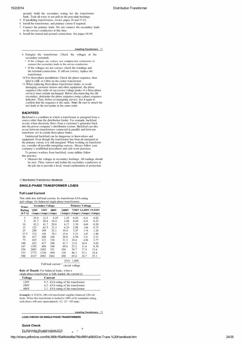
SINGLE-PHASE TRANSFORMER LOADS
Full Load Current
This table lists full load current, by transformer kVA ratingand voltage, for balanced single-phase transformers.
Trans. Secondary Voltage
Primary Voltage
Rating 120V 240V 480V 2400V 7200V 14,400V 19,920V(kVA) (Amps) (Amps) (Amps) (Amps) (Amps) (Amps) (Amps)
3 25.0 12.5 6.25 1.25 0.42 0.21 0.025 41.7 20.8 10.4 2.08 0.69 0.35 0.25
10 83.3 41.7 20.8 4.17 1.39 0.69 0.5015 125 62.5 31.3 6.25 2.08 1.04 0.7525 208 104 52.1 10.4 3.47 1.74 1.2637.5 313 156 78.1 15.6 5.21 3.47 1.8850 417 208 104 20.8 6.94 5.21 2.5175 625 313 156 31.3 10.4 6.94 3.77
100 833 417 208 41.7 13.9 10.4 5.02167 1392 696 348 69.6 23.2 11.6 8.38250 2083 1042 521 104 34.7 17.4 12.6333 2775 1338 694 139 46.3 23.1 16.8500 4167 2083 1042 208 69.4 34.7 25.1
kVA × 1,000Full load current =
Rule of Thumb: For balanced loads, when asingle-phase transformer is fully loaded, the current is:
Voltage Current
120V 8.3 × kVA rating of the transformer240V 4.2 × kVA rating of the transformer480V 2.1 × kVA rating of the transformer
Example: A 25 kVA, 240-volt transformer supplies balanced 120-voltloads. When this transformer is loaded to 100% of its nameplate rating,each phase will carry approximately: 4.2 × 25 = 105 amps.
circuit voltage
LOAD CHECKS ON SINGLE-PHASE TRANSFORMERS
Quick Check
To determine the approximate kVA b
anload on a single-phase transformer:
Installing Transformers 53
15/2/2014 Distribution Transformer
http://share.pdfonline.com/fdc380b1f0af4b4e99a756cf8f91a580/Dist.Trans.%20Handbook.htm 25/35
1. Measure the current in the two
line conductors
2. Add the amps together
3. Multiply by 120
4. Move the decimal point three
places to the left
120V
Example: If the readingsare 55A and 60A:
55A+60A
–——115A
115 × 120 = 13800The load is 13.8 kVA
120V
240V
Complete Calculation
Calculate the load on each half of the transformer separately,then add them together to determine the full load.
current a × voltage a-to-n 1,000
current b × voltage b-to-n1,000
Example: The readings on a 25 kVA transformer are 30A and 160A:
Total load in kVA =30 × 120
+160 × 120
1,000
1,000
= 3.6 + 19.2
=22.8 kVA
The total load is within the transformer rating, but one secondarywinding exceeds 12.5 kVA and is severely overloaded.
Note: Don’t use this quick check if there is
considerable imbalance between the two
current readings. Instead, use the Complete
Calculation, and verify that each load is less
than half the kVA rating of the transformer.
Total load in kVA = +
THREE-PHASE TRANSFORMER LOADS
Transformer
Secondary Voltage
Primary Voltage
Rating 208V 240V 347V 480V 600V 4160V 12,470V 24,900V 34,500V(kVA) (Amps) (Amps) (Amps) (Amps) (Amps) (Amps) (Amps) (Amps) (Amps)
30 83.3 72.2 49.9 36.1 28.9 4.16 1.39 0.70 0.5045 125 108 74.9 54.1 43.3 6.24 2.08 1.04 0.7575 208 180 124 90.2 72.2 10.4 3.47 1.74 1.26
112.5 312 271 187 135 108 15.6 5.20 2.61 1.88150 416 361 250 180 144 20.8 6.94 3.48 2.51225 625 541 374 271 217 31.2 10.4 5.22 3.77300 833 722 499 361 289 41.6 13.9 6.96 5.02500 1388 1203 832 601 481 69.4 23.2 11.6 8.37750 2082 1804 1248 902 722 104 34.7 17.4 12.6
1000 2776 2406 1664 1203 962 139 46.3 23.2 16.81500 4164 3608 2496 1804 1443 208 69.5 34.8 25.12000 5552 4811 3328 2406 1925 278 92.6 46.4 33.5
kVA × 1,000Full load current per phase =
voltage (line to line) × 1.73
Han
db
oo
k T
ran
sfo
rme
r Dis
tribu
tion
54
Installing Transformers 55
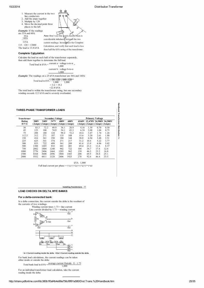
LOAD CHECKS ON DELTA, WYE BANKS
For a delta-connected bank:
In a delta connection, the current outside the delta is the resultant ofthe currents of two windings.
Winding current times 1.73 = line currentLine current divided by 1.73 = winding current
a
In In
Out
T1 InbT3
T2 Out
In Inc
Out
Out
A
B
C
T1 In In In In T3
In Out Out InOut
a
b
Out
c
Out
In = Current reading inside the delta. Out = Current reading outside the delta.
For bank load calculations, the current readings can be takeneither inside or outside the delta:
average current Outside × E × 1.731,000
For an individual transformer load calculation, take the currentreading inside the delta:
In Out
T2
Total bank load in kVA =
15/2/2014 Distribution Transformer
http://share.pdfonline.com/fdc380b1f0af4b4e99a756cf8f91a580/Dist.Trans.%20Handbook.htm 26/35
Individual transformer load in kVA = 1,000
To calculate the total bank load in kVA using this method, calculatethe load for each transformer, then add the three kVA loads together.
current Inside × E
56 Distribution Transformer Handbook
For a wye-connected bank:
To calculate the kVA load for a three-phase wye bank, calculate theload for each transformer, then add the three kVA loads together.
Transformer load A in kVA = 1,000
Transformer load B in kVA = 1,000
Transformer load C in kVA = 1,000
Total bank load in kVA = Load A + Load B + Load C
This method allows you to determine if any individual transformer isoverloaded.
Alternate method
I(average) × E(line to line) × 1.731,000
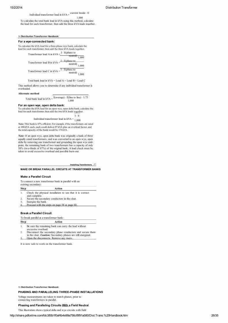
For an open wye, open delta bank:To calculate the kVA load for an open wye, open delta bank, calculate theload for each transformer, then add the two kVA loads together.
I × EIndividual transformer load in kVA =
Note: This bank is 87% efficient. For example, if the transformers are ratedat 100 kVA each, each could deliver 87 kVA plus an overload factor, andthe total capacity of the bank would be 174 kVA.
Note: If an open wye, open delta bank was originally a bank of threeequally sized transformers, and was converted to an open wye, opendelta by removing one transformer and grounding the open wye mid-point, the remaining bank of two transformers has a capacity of only58% (two-thirds of 87%) of the original bank. A load check must betaken to avoid excessive overload and possible burn-out.
I × E(phase toneutral)
I × E(phase toneutral)
I × E(phase toneutral)
Total bank load in kVA =
1,000
Installing Transformers 57
MAKE OR BREAK PARALLEL CIRCUITS AT TRANSFORMER BANKS
Make a Parallel Circuit
To connect a new transformer bank in parallel with anexisting secondary:
Step Action
1. Check the physical installation to see that it is correctand complete.
2. Secure the secondary conductors in the clear.3. Energize the bank.4. Proceed with the steps on page 58 or page 60.
Break a Parallel Circuit
To break parallel at a transformer bank:
Step Action
1. Be sure the remaining bank can carry the load withoutexcessive overload.
2. Disconnect the secondary phase conductors and secure themin the clear. Caution: Secondary phases are still energized.
3. Open the disconnects. Remove any risers.
It is now safe to work on the transformer bank.
58 Distribution Transformer Handbook
PHASING AND PARALLELING THREE-PHASE INSTALLATIONS
Voltage measurements are taken to match phases, prior toconnecting transformers in parallel.
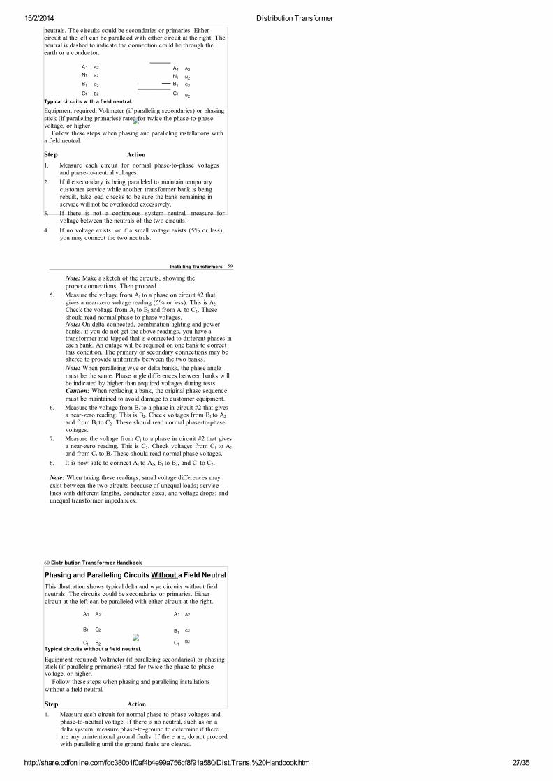
Phasing and Paralleling Circuits With a Field Neutral
This illustration shows typical delta and wye circuits with field
15/2/2014 Distribution Transformer
http://share.pdfonline.com/fdc380b1f0af4b4e99a756cf8f91a580/Dist.Trans.%20Handbook.htm 27/35
neutrals. The circuits could be secondaries or primaries. Eithercircuit at the left can be paralleled with either circuit at the right. Theneutral is dashed to indicate the connection could be through theearth or a conductor.
A A
N N
B C
B C
B
Typical circuits w ith a field neutral.
Equipment required: Voltmeter (if paralleling secondaries) or phasingstick (if paralleling primaries) rated for twice the phase-to-phasevoltage, or higher.
Follow these steps when phasing and paralleling installations witha field neutral.
Step Action
1. Measure each circuit for normal phase-to-phase voltagesand phase-to-neutral voltages.
2. If the secondary is being paralleled to maintain temporarycustomer service while another transformer bank is beingrebuilt, take load checks to be sure the bank remaining inservice will not be overloaded excessively.
3. If there is not a continuous system neutral, measure forvoltage between the neutrals of the two circuits.
4. If no voltage exists, or if a small voltage exists (5% or less),you may connect the two neutrals.
A1 A21 2
N1 N2 1 2
1 2 1 2
C1 B2 C12
Installing Transformers 59
Note: Make a sketch of the circuits, showing theproper connections. Then proceed.
5. Measure the voltage from A to a phase on circuit #2 thatgives a near-zero voltage reading (5% or less). This is A .Check the voltage from A to B and from A to C . Theseshould read normal phase-to-phase voltages.Note: On delta-connected, combination lighting and powerbanks, if you do not get the above readings, you have atransformer mid-tapped that is connected to different phases ineach bank. An outage will be required on one bank to correctthis condition. The primary or secondary connections may bealtered to provide uniformity between the two banks.
Note: When paralleling wye or delta banks, the phase anglemust be the same. Phase angle differences between banks willbe indicated by higher than required voltages during tests.Caution: When replacing a bank, the original phase sequencemust be maintained to avoid damage to customer equipment.
6. Measure the voltage from B to a phase in circuit #2 that givesa near-zero reading. This is B . Check voltages from B to Aand from B to C . These should read normal phase-to-phasevoltages.
7. Measure the voltage from C to a phase in circuit #2 that givesa near-zero reading. This is C . Check voltages from C to Aand from C to B These should read normal phase voltages.
8. It is now safe to connect A to A , B to B , and C to C .
Note: When taking these readings, small voltage differences mayexist between the two circuits because of unequal loads; servicelines with different lengths, conductor sizes, and voltage drops; andunequal transformer impedances.
1
2
1 2 1 2
1
2 1 2
1 2
1
2 1 2
1 2
1 2 1 2 1 2
60 Distribution Transformer Handbook
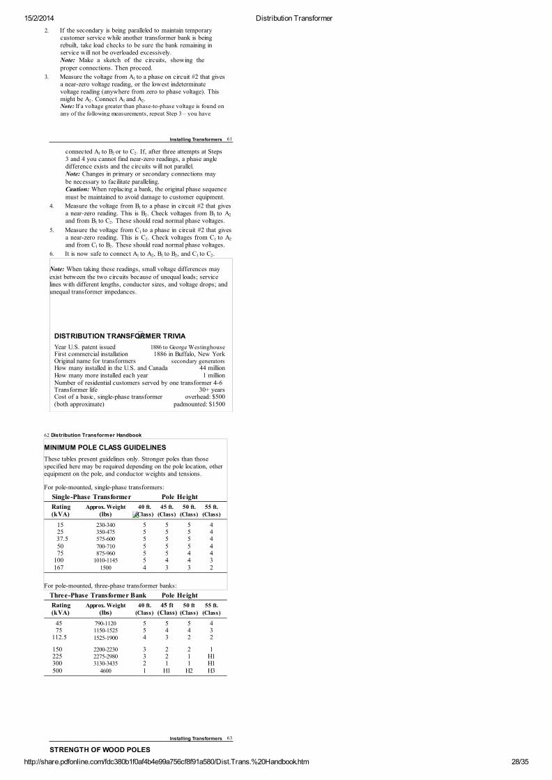
Phasing and Paralleling Circuits Without a Field Neutral
This illustration shows typical delta and wye circuits without fieldneutrals. The circuits could be secondaries or primaries. Eithercircuit at the left can be paralleled with either circuit at the right.
B
C B C
Typical circuits w ithout a field neutral.
Equipment required: Voltmeter (if paralleling secondaries) or phasingstick (if paralleling primaries) rated for twice the phase-to-phasevoltage, or higher.
Follow these steps when phasing and paralleling installationswithout a field neutral.
Step Action
1. Measure each circuit for normal phase-to-phase voltages andphase-to-neutral voltage. If there is no neutral, such as on adelta system, measure phase-to-ground to determine if thereare any unintentional ground faults. If there are, do not proceedwith paralleling until the ground faults are cleared.
A1 A2 A1 A2
B1 C21
C2
1 2 1B2
15/2/2014 Distribution Transformer
http://share.pdfonline.com/fdc380b1f0af4b4e99a756cf8f91a580/Dist.Trans.%20Handbook.htm 28/35
2. If the secondary is being paralleled to maintain temporarycustomer service while another transformer bank is beingrebuilt, take load checks to be sure the bank remaining inservice will not be overloaded excessively.Note: Make a sketch of the circuits, showing theproper connections. Then proceed.
3. Measure the voltage from A to a phase on circuit #2 that givesa near-zero voltage reading, or the lowest indeterminatevoltage reading (anywhere from zero to phase voltage). Thismight be A . Connect A and A .Note: If a voltage greater than phase-to-phase voltage is found onany of the following measurements, repeat Step 3 – you have
1
2 1 2
Installing Transformers 61
connected A to B or to C . If, after three attempts at Steps3 and 4 you cannot find near-zero readings, a phase angledifference exists and the circuits will not parallel.Note: Changes in primary or secondary connections maybe necessary to facilitate paralleling.Caution: When replacing a bank, the original phase sequencemust be maintained to avoid damage to customer equipment.
4. Measure the voltage from B to a phase in circuit #2 that givesa near-zero reading. This is B . Check voltages from B to Aand from B to C . These should read normal phase voltages.
5. Measure the voltage from C to a phase in circuit #2 that givesa near-zero reading. This is C . Check voltages from C to Aand from C to B . These should read normal phase voltages.
6. It is now safe to connect A to A , B to B , and C to C .
Note: When taking these readings, small voltage differences mayexist between the two circuits because of unequal loads; servicelines with different lengths, conductor sizes, and voltage drops; andunequal transformer impedances.
DISTRIBUTION TRANSFORMER TRIVIA
Year U.S. patent issued 1886 to George WestinghouseFirst commercial installation 1886 in Buffalo, New YorkOriginal name for transformers secondary generatorsHow many installed in the U.S. and Canada 44 millionHow many more installed each year 1 millionNumber of residential customers served by one transformer 4-6Transformer life 30+ yearsCost of a basic, single-phase transformer overhead: $500(both approximate) padmounted: $1500
1 2 2
1
2 1 2
1 2
1
2 1 2
1 2
1 2 1 2 1 2
62 Distribution Transformer Handbook
MINIMUM POLE CLASS GUIDELINES
These tables present guidelines only. Stronger poles than thosespecified here may be required depending on the pole location, otherequipment on the pole, and conductor weights and tensions.
For pole-mounted, single-phase transformers:
Single-Phase Transformer
Pole Height
Rating Approx. Weight 40 ft. 45 ft. 50 ft. 55 ft.(kVA) (lbs) (Class) (Class) (Class) (Class)
15 230-340 5 5 5 425 350-475 5 5 5 437.5 575-600 5 5 5 450 700-710 5 5 5 475 875-960 5 5 4 4
100 1010-1145 5 4 4 3167 1500 4 3 3 2
For pole-mounted, three-phase transformer banks:
Three-Phase Transformer Bank Pole Height
Rating Approx. Weight 40 ft. 45 ft 50 ft 55 ft.(kVA) (lbs) (Class) (Class) (Class) (Class)
45 790-1120 5 5 5 475 1150-1525 5 4 4 3
112.5 1525-1900 4 3 2 2
150 2200-2230 3 2 2 1225 2275-2980 3 2 1 H1300 3130-3435 2 1 1 H1500 4600 1 H1 H2 H3
Installing Transformers 63
STRENGTH OF WOOD POLES
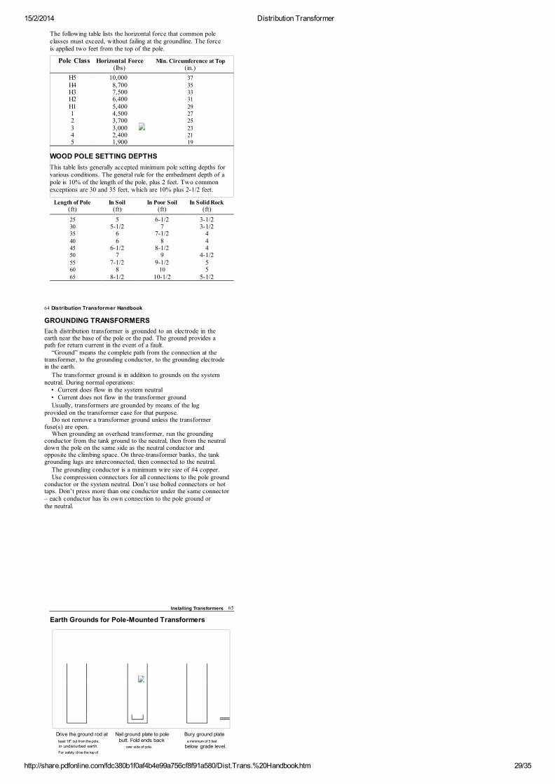
15/2/2014 Distribution Transformer
http://share.pdfonline.com/fdc380b1f0af4b4e99a756cf8f91a580/Dist.Trans.%20Handbook.htm 29/35
The following table lists the horizontal force that common poleclasses must exceed, without failing at the groundline. The forceis applied two feet from the top of the pole.
Pole Class Horizontal Force Min. Circumference at Top
(lbs) (in.)
H5 10,000 37H4 8,700 35H3 7,500 33H2 6,400 31H1 5,400 291 4,500 272 3,700 253 3,000 234 2,400 215 1,900 19
WOOD POLE SETTING DEPTHS
This table lists generally accepted minimum pole setting depths forvarious conditions. The general rule for the embedment depth of apole is 10% of the length of the pole, plus 2 feet. Two commonexceptions are 30 and 35 feet, which are 10% plus 2-1/2 feet.
Length of Pole In Soil In Poor Soil In Solid Rock(ft) (ft) (ft) (ft)
25 5 6-1/2 3-1/230 5-1/2 7 3-1/235 6 7-1/2 440 6 8 445 6-1/2 8-1/2 450 7 9 4-1/255 7-1/2 9-1/2 560 8 10 565 8-1/2 10-1/2 5-1/2
64 Distribution Transformer Handbook
GROUNDING TRANSFORMERS
Each distribution transformer is grounded to an electrode in theearth near the base of the pole or the pad. The ground provides apath for return current in the event of a fault.
“Ground” means the complete path from the connection at thetransformer, to the grounding conductor, to the grounding electrodein the earth.
The transformer ground is in addition to grounds on the systemneutral. During normal operations:
• Current does flow in the system neutral• Current does not flow in the transformer groundUsually, transformers are grounded by means of the lug
provided on the transformer case for that purpose.Do not remove a transformer ground unless the transformer
fuse(s) are open.When grounding an overhead transformer, run the grounding
conductor from the tank ground to the neutral, then from the neutraldown the pole on the same side as the neutral conductor andopposite the climbing space. On three-transformer banks, the tankgrounding lugs are interconnected, then connected to the neutral.
The grounding conductor is a minimum wire size of #4 copper.Use compression connectors for all connections to the pole ground
conductor or the system neutral. Don’t use bolted connectors or hottaps. Don’t press more than one conductor under the same connector– each conductor has its own connection to the pole ground orthe neutral.
Installing Transformers 65
Earth Grounds for Pole-Mounted Transformers
Drive the ground rod at Nail ground plate to pole Bury ground plate
least 18" out from the pole, butt. Fold ends back a minimum of 5 feet
in undisturbed earth. over side of pole. below grade level.For safety, drive the top of
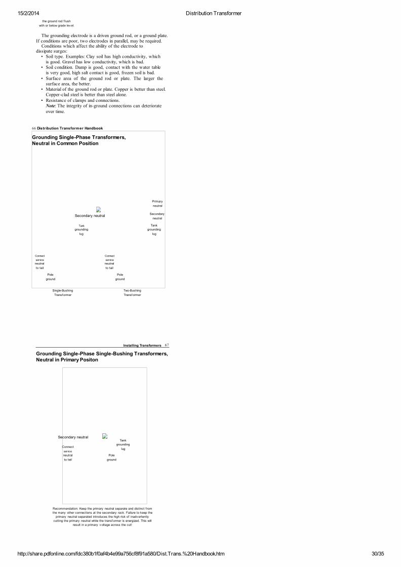
15/2/2014 Distribution Transformer
http://share.pdfonline.com/fdc380b1f0af4b4e99a756cf8f91a580/Dist.Trans.%20Handbook.htm 30/35
the ground rod f lush
with or below grade lev el.
The grounding electrode is a driven ground rod, or a ground plate.If conditions are poor, two electrodes in parallel, may be required.
Conditions which affect the ability of the electrode todissipate surges:
• Soil type. Examples: Clay soil has high conductivity, whichis good. Gravel has low conductivity, which is bad.
• Soil condition. Damp is good, contact with the water tableis very good, high salt contact is good, frozen soil is bad.
• Surface area of the ground rod or plate. The larger thesurface area, the better.
• Material of the ground rod or plate. Copper is better than steel.Copper-clad steel is better than steel alone.
• Resistance of clamps and connections.Note: The integrity of in-ground connections can deteriorateover time.
66 Distribution Transformer Handbook
Grounding Single-Phase Transformers,Neutral in Common Position
Primary
neutral
Secondary neutralSecondary
neutral
Tank Tank
grounding grounding
lug lug
Connect Connect
service service
neutral neutral
to tail to tail
Pole Pole
ground ground
Single-Bushing Two-Bushing
Transf ormer Transf ormer
Installing Transformers 67
Grounding Single-Phase Single-Bushing Transformers,Neutral in Primary Positon
Secondary neutralTank
Connectgrounding
lugservice
neutral Pole
to tail ground
Recommendation: Keep the primary neutral separate and distinct f rom
the many other connections at the secondary rack. Failure to keep the
primary neutral separated introduces the high risk of inadv ertently
cutting the primary neutral while the transf ormer is energized. This will
result in a primary v oltage across the cut!
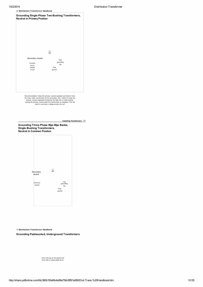
15/2/2014 Distribution Transformer
http://share.pdfonline.com/fdc380b1f0af4b4e99a756cf8f91a580/Dist.Trans.%20Handbook.htm 31/35
68 Distribution Transformer Handbook
Grounding Single-Phase Two-Bushing Transformers,Neutral in Primary Positon
Secondary neutralTank
Connectgrounding
lugservice
neutral Pole
to tail ground
Recommendation: Keep the primary neutral separate and distinct f rom
the many other connections at the secondary rack. Failure to keep the
primary neutral separated introduces the high risk of inadv ertently
cutting the primary neutral while the transf ormer is energized. This will
result in a primary v oltage across the cut!
Installing Transformers 69
Grounding Three-Phase Wye-Wye Banks,Single-Bushing Transformers,Neutral in Common Positon
Secondary
neutral
CommonTank
groundingneutral
lug
Pole
ground
70 Distribution Transformer Handbook
Grounding Padmounted, Underground Transformers
Driv e the top of the ground rod
f lush with or below grade lev el.
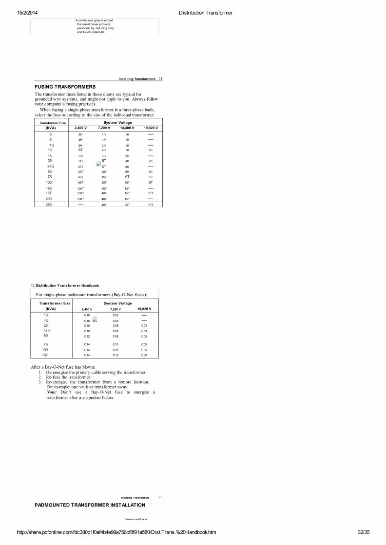
15/2/2014 Distribution Transformer
http://share.pdfonline.com/fdc380b1f0af4b4e99a756cf8f91a580/Dist.Trans.%20Handbook.htm 32/35
A continuous ground around
the transf ormer protects
personnel by reducing step
and touch potentials.
Installing Transformers 71
FUSING TRANSFORMERS
The transformer fuses listed in these charts are typical forgrounded wye systems, and might not apply to you. Always followyour company’s fusing practices.
When fusing a single-phase transformer in a three-phase bank,select the fuse according to the size of the individual transformer.
Transformer Size
System Voltage
(kVA) 2,400 V 7,200 V 14,400 V 19,920 V
3 2H
1H
1H —5 3H
1H
1H —7.5 5H
2H
1H —10 6T
2H
1H 1H
15 10T
3H
2H —25 15T
6T
3H 2H
37.5 25T
6T
3H —50 25T
10T
5H 3H
75 40T
15T
6T 5H
100 65T
25T
10T 6T
150 100T 25T
15T —167 100T 40T
15T 10T
200 100T 40T
15T —250 —
40T
25T 15T
72 Distribution Transformer Handbook
For single-phase padmount transformers (Bay-O-Net fuses):
Transformer Size
System Voltage
(kVA) 2,400 V 7,200 V 19,920 V
10 C10 C03 —15 C10 C03 —25 C10 C05 C03
37.5 C10 C08 C03
50 C12 C08 C05
75 C14 C10 C05
100 C14 C10 C05
167 C14 C12 C05
After a Bay-O-Net fuse has blown:1. De-energize the primary cable serving the transformer.2. Re-fuse the transformer.3. Re-energize the transformer from a remote location.
For example: one vault or transformer away.Note: Don’t use a Bay-O-Net fuse to energize atransformer after a suspected failure.
Installing Transformers 73
PADMOUNTED TRANSFORMER INSTALLATION
Pressure relief valve
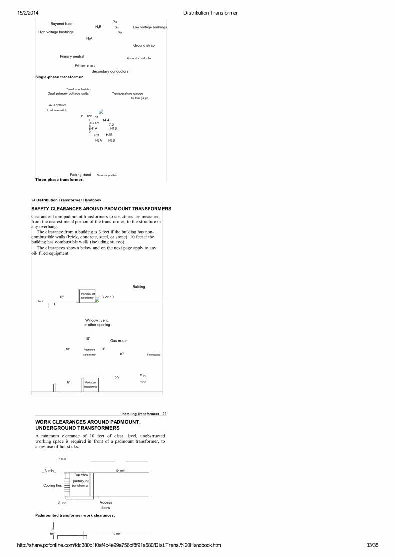
15/2/2014 Distribution Transformer
http://share.pdfonline.com/fdc380b1f0af4b4e99a756cf8f91a580/Dist.Trans.%20Handbook.htm 33/35
Bay-O-Net fuses
Loadbreak switch
H1 H2C H3
L
14.4 O OPEN
7.2 S
EH1A H1B D
H2A H2B
H3A H3B
Parking stand Secondary cables
Bayonet fuseH B
x
x Low voltage bushings
High voltage bushings
x
H A
Ground strap
Primary neutral Ground conductor
Primary phase
Secondary conductors
Single-phase transformer.
Transformer feed-thru
Dual primary voltage switch
Temperature gauge
Oil level gauge
Three-phase transformer.
1
3
1
2
1
74 Distribution Transformer Handbook
SAFETY CLEARANCES AROUND PADMOUNT TRANSFORMERS
Clearances from padmount transformers to structures are measuredfrom the nearest metal portion of the transformer, to the structure orany overhang.
The clearance from a building is 3 feet if the building has non-combustible walls (brick, concrete, steel, or stone), 10 feet if thebuilding has combustible walls (including stucco).
The clearances shown below and on the next page apply to anyoil- filled equipment.
Building
15'
Padmount
3' or 10'
transformer
Pool
Window , vent,
or other opening
10"Gas meter
10' Padmount 3'
Fire escape
transformer 10'
20'Fuel
Padmount
tank 6'
transformer
Installing Transformers 75
WORK CLEARANCES AROUND PADMOUNT,UNDERGROUND TRANSFORMERS
A minimum clearance of 10 feet of clear, level, unobstructedworking space is required in front of a padmount transformer, toallow use of hot sticks.
3' min
10' min
3' min
Top view
padmount
Cooling f ins
transf ormer
Access
3'
min
doors
Padmounted transformer work clearances.
3'
10' min
min
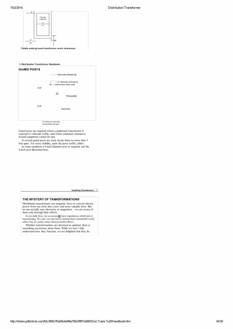
15/2/2014 Distribution Transformer
http://share.pdfonline.com/fdc380b1f0af4b4e99a756cf8f91a580/Dist.Trans.%20Handbook.htm 34/35
Top view
v ault lid
3' 3' min
min
Totally underground transformer work clearances.
76 Distribution Transformer Handbook
GUARD POSTS
Concrete domed top
4" diameter Schedule
40 galvanized steel pipe
3'-6"
Final grade
2'-6"
Concrete
6" minimum concrete
surrounding the post
Guard posts are required where a padmount transformer isexposed to vehicular traffic, and where minimum clearancesaround equipment cannot be met.
If several guard posts are used, locate them no more than 5feet apart. For extra visibility, paint the posts traffic yellow.
In some situations a 6-inch diameter post is required, not the4-inch post illustrated here.
Installing Transformers 77
THE MYSTERY OF TRANSFORMATIONS
Distribution transformers use magnetic force to convert electricpower from one form into a new and more valuable form. Butno one actually sees electricity or magnetism – we are aware ofthem only through their effects.
In our daily lives, we occasionally have experiences which provetransforming. We can’t see the forces behind these wonderful eventseither, but we surely notice their powerful effects.
Whether transformations are electrical or spiritual, there issomething mysterious about them. While we don’t fullyunderstand how they function, we are delighted that they do.

15/2/2014 Distribution Transformer
http://share.pdfonline.com/fdc380b1f0af4b4e99a756cf8f91a580/Dist.Trans.%20Handbook.htm 35/35
Convert PDF to HTML