distribution statement a - dtic.mil · the wing, fin and other components are completed for final...
TRANSCRIPT
s
THIS REPORT HAS BEEN DELIMITED
AND CLEARED FOR PUBLIC RELEASE
UNDER DOD DIRECTIVE 5200.20 AND
NO RESTRICTIONS ARE IMPOSED UPON
ITS USE AND DISCLOSURE.
DISTRIBUTION STATEMENT A
APPROVED FOR PUBLIC RELEASE;
DISTRIBUTION UNLIMITED.

TRI - SERVICE
D D C ,r?rar?nn/7Pijri JUN 24 1965
JlJCiWiU U LbQi) DOC-IRA E
v/sloL RESEARCH AIRCRAFT
REPORT NO. 2 1 2 7 - 9 3 3 0 28 IS APRIL 1965
NAVY CONTRACT NO. NOw 63 -0118-ci
*1
CD or-
X-22A PROGRESS REPORT NO. 2 MARCH 1965
t B E L L A E R O S Y S T E M S C O M P A N Y D I V I S I O N O F B E L L A E R O S P A C E C O R P O R A T I O N - A HXtTOHl C O M P A N Y
NOTICE: When govenunent or other drawings, speci- fications or other data are used for any purpose othei: them in connection with a definitely related government procurement operation, the U. S. Government thereby incurs no responsibility, nor any obligation whatsoever; and the fact that the Govem-
it may have formulated, furnished, or in any way supplied the said drawings, specifications, or other data is not to be regarded by implication or other- wise as in any manner licensing the holder or any other person or corporation, or conveying any rights or permission to manufacture, use or sell any patented invention that may in any way be related thereto.
■ . '.

O J I B E L L . A E R O S Y S T E M S c o i w w w r ^ e ^ P>u-fta/o A/, X
/ 2 X-22A TRI-SERVICE V/STOL AIRCRAFT
MONTHLY PROGRESS REPORT s", > Report ^o . 2127-
- 3 / 6> 5"~
933028
n) /? Af' ^5, a o i
This is the twenty-eight Monthly Progress Report as required in Section F(5) of the contract, and outlines progress for the period 1 March 1965 through 31 March 1965. For an illustration and a brief introduction of the X-22A program refer to reports prior to May 1964.
A.L6. Marchese Project Director X-22A PROGRAM

($ BELL. AEROSYSTEiVIS cxMvtfANV
CONTENTS
Section Page
I SUMMARY 1
II DESIGN 7 A. Flight Technology 7 B. Vehicle Structure 7 C. Design 9 D. Systems Support 11 E. Systems Analysis and Simulation 11
III MODELS 13 A. Wind Tunnel Test Program 13
1. l/3-Scale Powered Duct Model 13 2. Full-Scale Powered Duct Model 13 3. l/20-Scale Spin Model 13 4. Powered Free-Flight Model 13 5. 4/7-Scale Powered Airplane Model 13
IV TEST STANDS 14 A. Propulsion System Test Stand 14 B. Flight Control - Hydraulic System Test Stand 14
V MANUFACTURING 15
VI SUBCONTRACTORS 17 1. Propellers 17 2. Variable Stability System 17 3. Transmission System 17 4. Landing Gears 17 5. -136 Duct Support Tubes 18 6. Harmonie Drive System 18 7. Viscous Dampers 18 8. Gear Sectors 18
Report No. 2127-933028 ii

(fa BEUL AEROSYSTEiVtS GOMRANV
CONTENTS (CONT)
Section Page
VII GENERAL 19 A. Trips and Visitors 19 B. Open Items 19
ILLUSTRATIONS
Figure Page
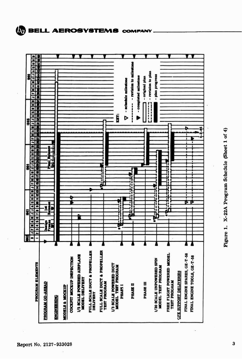
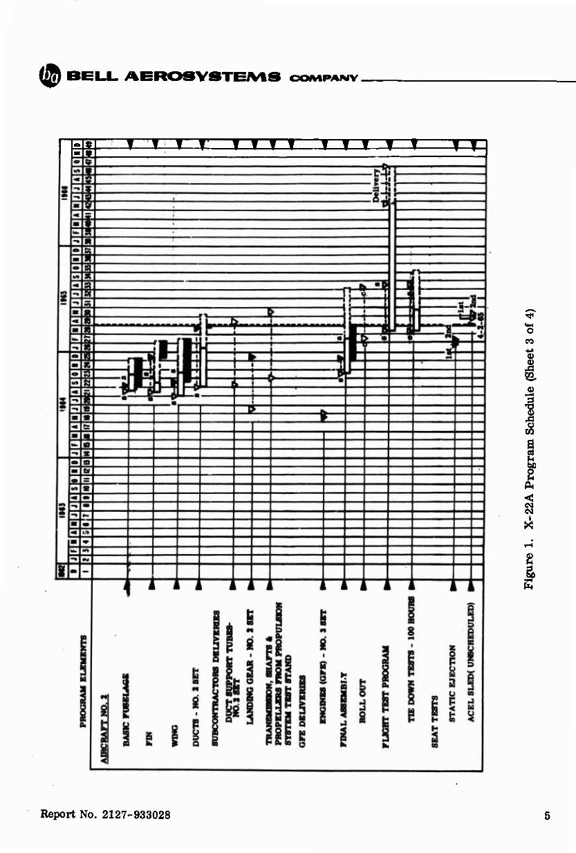
1 X-22A Program Schedule 3
Report No. 2127-933028 iii

($ BELL AEROSYSTEJVtS CXMVIPANV
I. SUMMARY
'Effort during the period was concentrated on the completion of aircraft No, 1 (Bu No. 1520) and on efforts required to continue the transmission system formal qualification on the test stand. Engineering liaison continued with shop and laboratory efforts. Flight test instrumentation progressed and test procedures were reviev/ed for coordinated efforts,
-During March, the empty weight calculation for the aircraft increased 13,7 pounds to a total of 549.8 pounds over target. The increases were in access door additions, general interference and installation changes, landing gear and electrical installation./
The Spin model test report was submitted to BuWeps. Analyses and test report preparation continued on the 1/3 and the Full Scale powered duct models. Activity on the powered Free Flight model is expected ^o resume in April. Data from the 4/7 Scale powered NASA-Ames model tests will be sent to Bell early in April.
The Propulsion System test stand operated 12.0 hours during March,, in which 11.0 hours of transmission qualification time was accumulated. However, on 6 March, tests were stopped as wear in the gearboxes was detected'. This was in part caused by bearings turning in their bore mountings. The fuJJr^set of boxes were returned to SPECO for rework and repair which included tightening of the bearing interference fit, plating to inhibit fretting, increasing the torjjwß of bearing retaining nuts, and to replace some installations of titanium with steeU-^the repairs were completed and the reinstal- lation was in process at the close (jpfne period. Stand resumption is scheduled for 5 April.
Phase I hydjpatTlic system tests were sati: iactorily completed and Phase II tests while progressing normally, were interrupted 15 March on the Flight Control - Hydraulic Test Stand^This was done to install the duct rotation system, incorporate required change^an the mixing box and rework swivel fittings at the eleven. This work is sche- duled-lfor completion in mid-April, for resumption of eleven instability tests and the last ph^6e of hydraulic system testing.
.The second aircraft set of components have progressed, paced by the vendors com- pletion of the duct support tubes, their /-splfriing and mating with the harmonic drive units. The wing, fin and other components are completed for final assembly installation.
The static test article and components are moving well into completion. Fixtures for static testing, and the instrumentation required have progressed for the start of tests scheduled in May
Report No. 2127-933028

(© BELL. AEROSYSTEiVlS COIVIPAMV
•^ A full project coordinated effort in the shop has continued through the period to complete the manufacturing phase of aircraft No. 1, Bu No. 1520, in mid-April. It is then scheduled to the flight test department for completion of systems functional checks prior to rollout.vThe program planning as of the end of March is shown on the program schedule (1*^ Figure 1).
Planning for tie formal rollout ceremony of aircraft No. 1 on 25 May 1965 is continuing between Hell anoLBuWeps. Invitations will be extended to representatives of all services and the aircraft industry to attend.
1 I
Report No. 2127-933028
I
($ OOfMRANV
o
I
CO
Report No. 2127-933028

(^ BEUL AEROSYSTEAAS OOIMPANV
o
+» 0)
% to, (0
>—I
1
2
Report No. 2127-933028
($ 7) B6L.L. AEROSYSTEiVtS OOMPANV
s.S. Tiyy TTIT iiifi T^C
o CO
I l-H
I «1 a 2 I
c« i
X
2
Report No. 2127-933028

(2) BELL. AEROSVaTEJVtS OCMVIRAMV
I e
I
e 1 i i
g
Hl g S
i
I s
l o
I
«g
w ^
2
Report No. 2127-933028

Ifö BELL. AEROSYSTEMS CXNVIRANV
II. DESIGN
A. FLIGHT TECHNOLOGY
1. Performance
The drag and propulsion data for the second issue of the standard aircraft characteristics charts was discussed in a meeting at BuWeps. Verbal agreement was reached on drag values. BuWeps will discuss propulsion data with NASA-Ames.
2. Stability and Control
Work was begun on the seventh revision to the stability and control report which is scheduled for submittal in April. The revision will incorporate the hinge moment data, duct stall boundary effects and propulsion data which were obtained from the results of the Phase II, full scale ducted propeller model tests.
3. Propulsion Analysis
Using the latest engine specifications, the installed engine performance has been calculated for use in performance calculations. Final data have been received from Ames for the full scale ducted propeller model tests. These data will be used in final propulsion efficiency predictions.
B. VEHICLE STRUCTURES
1. Criteria and Loads
Eleven buffet loads measured during Phase II testing at NASA-Ames have been investigated from a fatigue point of view. Due to structural differences between the test eleven and the flight hardware, the elevon actuators on the left side of No. 1 airplane have been strain gaged and calibrated for load measurement. This will pro- vide more accurate data for analysis.
Analytical work has been concentrated on the determination of magnitudes and distributions for the aerodynamic loads report.
Report No. 2127-933028

(S) BELL AEROSYSTEiVtS OOIMPANV
Structural Tests
Work was continued on evaluation of the drop test program for preparation of the drop test plan report. An investigation of the availability of the special equipment required in the drop test program was initiated.
The revision of the Report 2127-929001, "Status of Structural Test" has been drafted and is being reviewed. Methods for monitoring strain and deflection data while conducting the static tests was investigated. Fabrication of the basic structure for supporting the static test airframe, the special tension pads for the vertical fin loading, and the basic support structure for the aft duct assembly have all been completed. Work is continuing on the design and fabrication of whiffle trees and loading arrangements for the aft duct assembly tests.
The detail planning of loading jack assignments for the engine mount, fin, fuselage, wing and landing gear tests was completed.
3. Aeroelasticity
To establish system natural frequencies, a forced vibration survey of engines and propulsion system shafting and gearboxes on aircraft No, 1 is scheduled prior to rollout. Engine crotches, fuselage shaft bearing hangers and representative gearboxes will be monitored during initial runup.
Detailed planning for the ground forced vibration test is in progress. The nose boom containing pressure pickups and pitch and yaw vanes has been checked for natural frequency and found to have the fundamental at 8.0 cps. This meets minimum frequency requirements for compatibility with the variable stability system.
4. Weights
Weight empty increases totaling 13.7 pounds have been incorporated this month The current overweight is now 549.8 pounds. Weight changes are for:
(1) +1.8 pounds for additional access doors. (2) +3.1 pounds to eliminate interferences. (3) +2.9 pounds to facilitate installation (4) +3.0 pounds additional electrical requirements. (5) +2.6 pounds to provide thermal relief protection in the landing gear. (6) +0.3 pound for miscellaneous.
Weight and balance status report No. 13 was submitted to BuWeps during this period.
Report No. 2127-933028 8
(© BELL. AEROSYSTEiVlS OOIMRANV
C. DESIGN
1. General
Manufacturing liaison and test stand coordination are the major items of work in the design area. During this report period, elimination of interferences and the addi- tion of access openings were accomplished.
2. Airframe
The major efforts in airframe design are drawing changes and liaison with manufacturing. Engine cowls and landing gear doors required minor rework action to provide good match up of mating surfaces. Access panels to facilitate installation and servicing of components and airframe rework to eliminate interferences have been in- corporated as necessary.
a. Flight Controls
Revisions and additions to the flight control rigging procedure were com- pleted and distributed to the operating departments.
Rework on the United Shoe Machinery wave generators for the harmonic drives is being investigated by the vendor and Bell. Tests required to prove the drive design were defined.
The eleven stability problem found on the flight control hydraulic system test stand was corrected on the aircraft by adding a spring preload in much the same manner as on the test stand. Completion of the Procedure II hydraulic subsystems tests is awaiting the final installations of components on the test stand. The duct rotation harmonic drives and simulated ducts are being installed on the test stand. Changes to trim and feel system specifications were accomplished.
Design of covers and guards for the mechanisms in the mixing box was completed. Design of the eleven load relievers for the rear elevon actuators was initiated, and attitude stick changes to accommodate variable stability system requirements were completed.
Normal engineering liaison with manufacturing during fabrication and installation of control system components into the flight aircraft is in progress.
b. Equipment and Ground Equipment
Design of the installation of duct rotation switches on the pilot collective pitch sticks was released to manufacturing.
Report No. 2127-933028
I
(® BEUL AER09Y8TEiVt8 OCNVIPANV
3. Propulsion Design
a. Propulsion Design (Aircraft)
There has been no effort on new hardware for the aircraft during this period. Special tools have all been made for the airplane transmission installation, several drawings are being completed for special tools that were fabricated during assembly installation.
b. Propulsion System
Propulsion liaison with manufacturing systems installations continued through March and updating of the propulsion schematics progressed. The checkout pro- cedures for the X-22A Propulsion System on the airplane were completed.
On occasions, since the Propulsion System Test Stand was initiated, the engines have evidenced an area of intolerable vibration. Checks have isolated the Trans- mission System from the basic engine to pin-point the sources.
Each time an engine change was made, for FOD, seizure, etc., a vibration problem arose. The four original engines were of the more current split bearing power turbine configuration, while the available replacement engines included an earlier 1 piece bearing power turbine. In each occasion, the vibration was eliminated by our removal of the Power Turbine, from the replacement engine and reinstalling the Power Turbine frorr the original engine.
With the recent engine seizure the engine was shipped to overhaul on priority DIR. The results have not localized the vibration source. However, as the more current split bearing power turbine installations have been satisfactory to date. Bell has recommended that an equal exchange be arranged to supply all of the latter configuration engines to free the program from further delay and increased cost from this problem. This is being currently discussed with BuWeps.
4. Hydraulic and Landing Gear
Major engineering effort has continued in the preparation of checkout procedur
a. Landing Gear
Both the landing gear and brake system check out procedures have been completed.
Report No. 2127-933028 10

($
The gear manufacturer is replacing all retraction actuator bodies with steel parts as a result ot damage which occurred when the main gear was allowed to free- fall.
The brake assemblies were reworked by Goodyear for attaching a disc guide to prevent excessive axial movement of the brake disc.
b. Hydraulic System
The Flush, Fill, and Check-out Procedure for the aircraft has been com- pleted.
The rework on the first forward roll-yaw boost actuator was completed and the actuator has been satisfactorily installed in aircraft No. 1.
The addition of pressure-operated by-pass valves in the duct rotation system is under investigation. This would eliminate a possible hydraulic lock condition in the event that one hydraulic system fails.
The vendor design approval test report on the pitch boost actuator was reviewed and approved. Based on the test results pins on this actuator, and similar pins on the two roll-yaw boost actuators, will be replaced with pins of different material and hardness prior to first flight.
5. Electrical and Electronics
Liaison with manufacturing was the major activity during the month. A checkout procedure of the electrical system for the aircraft was completed. Drawings were issued on the installation of the automatic direction finding receiver.
D. SYSTEMS SUPPORT
Recent revision to the propeller system is being studied for inputs to the inspection requirements handbook. The maintenance handbook continued in preparation and changes to Aerospace Ground Equipment were coordinated.
E. SYSTEMS ANALYSIS AND SIMULATION
Effort progressed in the areas of:
(1) The acceptance and handling of flight test calibration data;
(2) Reduction and summarization of propeller actuator response and thrust response to throttle steps;
Report No. 2127-933028 11
(&
(3) Troubleshooting test procedures for eleven and pitch boost stability;
(4) Liaison support during fabrication and testing of stability augmentation, feel and trim, and the variable stability systems.
Report No. 2127-933028 12

(2) BELL. AEROSYSTEiVtS OOIMRANV
HL MODELS
A. WIND TUNNEL TEST PROGRAM
1. l/3-Scale Powered Duct Model
The final data report for this model is approximately 40% complete. It is being prepared without inclusion of the static test of the model which has been delayed at David Taylor Model Basin.
2. Full-Scale Powered Duct Model
Final data for this model have been received from NASA-Ames and are being analyzed.
3. 1/20-Scale Spin Model
The data report for this model was submitted to BuWeps on 23 March 1965.
4. Powered Free-Flight Model (0.18 Scale)
There has been no activity on this model due to higher priority projects at NASA-Langley. Testing is expected to resume in April.
5. 4/7-Scale Powered Airplane (NASA-Ames) Model
A second series of tests was conducted on this model in the NASA-Ames 40 by 80 foot wind tunnel. The tests included ground effects in hover, transition, and level flight configurations. The data will be supplied to Bell early in April.
Report No. 2127-933028 13

t B E L L A E R O S Y S T E M S C O M P A N Y
IV. TEST STANDS
A. PROPULSION SYSTEM TEST STAND
The test stand was operated for 12.0 hours during the month. As of 31 March 1965, the test stand was operated for a total of 65.0 hours and 11.0 hours of qualification time was accumulated.
Repair of the propeller transfer bearing that was damaged last period was com-pleted 1 March and test stand operation resumed on 2 March. On 3 March, a fuel control malfunction occurred on engine No. 4 which produced an overspeed and overtorqued condition. The gas generator and fuel control portion of the engine were replaced and testing resumed again on 5 March. During operation on 5 March, there was positive indication of metallic (magnetic) particles in forward fuselage (No. 10) gearbox. This occurred again on 6 March for No. 10 and also aft fuselage (No. 9) gearbox. Testing was terminated on 6 March when oil temperature for No. 10 gearbox increased suddenly from 85 to 108°C.
A detailed examination showed that wear caused by some of the bearings turning on their bore mountings was taking place in the forward and aft fuselage gearboxes and in the four engine gearboxes. The full set of transmissions was returned to Steel Products where the necessary repairs were made. This included tightening up of the interference fit on the bore of the affected bearings, silver plating the shafts to assist in inhibiting fretting, and increasing the pinch on the bearings by torquing the retaining nuts to a much higher value and replacing an inner race and titanium spacer on the fuselage gearboxes with a specially designed roller bearing inner race. In addition, some of the liners were changed from titanium to steel.
These repairs were completed and the last gearbox was shipped back to Bell on 31 March 1965. The 50 hour qualification test is expected to resume 5 April.
It should also be noted that other than the wear condition noted above, the trans-missions were in excellent condition. Gear tooth faces showed no discernable wear, bearings showed no wear on their contacting surfaces and no cracks or other structural failures were found in any of the transmission hardware.
B. FLIGHT CONTROL - HYDRAULIC SYSTEM TEST STAND
Formal hydraulic system testing was satisfactorily continued to 15 March 1965 using a simple spring preload to compensate for the elevon instability condition. At this time, testing was stopped to permit installation of the duct rotation system, incor-porate the latest changes in the mixing box assembly and rework the elevon actuator swivel fittings. This work is expected to be completed 19 April 1965 and elevon instability testing and the last phase of hydraulic system testing will resume at this time. Report No. 2127-933028 14

($ B6L.L. AEROSYSTEiVtS CXMVIPANV
V. /MANUFACTURING
The shop effort continued in the last phases of component assembly and systems installations. Both aircraft final assembly operations progressed and the static test article and static components approached their completion points.
Duct Assemblies - The first ship set of ducts were completed and mated with duct support tubes and harmonic drives. A fifth duct has been completed and has been mated with the duct tube, which tube is now at United Shoe Machinery Co. being matched with a harmonic drive assembly. Three additional duct assemblies have been completed and are held waiting for the duct tubes from the vendor. A ninth duct shroud is nearing com- pletion in the fixture and will be completed with the incorporation of the duct support tube when available.
Strut Assemblies - One duct assembly is having the strut and centerbody assemblies mated. A second complete set of struts and centerbody is ready for assembly with the duct upon the availability of propeller and gearbox. Two additional centerbodys are currently in work. All horizontal and auxiliary struts for the second aircraft have been completed, with the vertical struts nearing completion.
Elevens - The four elevens for aircraft No. 1 have been processed through rework. Two of the second set have also been completed, a third in final riveting and the fourth due to be started in the fixture early in April. The tri-plane eleven details are in work and the initial assembly fixtures have been completed.
Stabilizers - Number 1 set of stabilizers (rear wing tips) have been completed, painted and installed. The second set have been completed and are ready for painting.
Cowls, Landing Gear Doors and Inlets - Both the number one set of nacelle cowls and main landing gear doors have been completed, fit to ship and in painting. The second set are in subassembly and in fixtures. The second aircraft air inlet assemblies are in subassembly work.
Fin and Wing ~ The second fin assembly was completed in the shop and checked in the Engineering Laboratory. The third fin was started in the fixture 1 March. The instrumentation has been completed and the skinning closcup is in progress for com- pletion early in April. The third wing was completed 25 March and is available for static test installation.
Report No. 2127-933028 15

(2) BEL.L. AEROSVSTE/VtS OOIVIRANV
Final Assembly - Bu No. 1520 (aircraft No. 1) has moved along with top priority. All four ducts with propellers have been installed and harmonic drives connected. The electric cabling and hookups have continued. Tubing is being mocked up and installed as system installations progress. The cleaning and painting of the aircraft has been completed as far as possible and cockpit furnishings placed and completion in process. The landing gear and doors, and eleven controls have been installed. Flushing and rigging procedures are being prepared.
Bu No. 1521 (aircraft No. 2) is following in final assembly. The wing has been installed and the fin available for fit. System installations are underway. The cabin, cockpit and tank areas have been completed. The nose gear is on hand for fit. One right propeller is available and in work for installation. The other right and two left propellers as well as transmission gearboxes and shafts will be available later from the propulsion system test stand. This availability controls the completion of aircraft No. 2.
The third fuselage, the static test article, was removed from the fixture and located on the final assembly area 2 March. Cleanup work and change incorporations has continued. The instrumentation wiring has been accomplished. Installation is progressing with the wing and the engine mount. The nose gear has been received from the vendor for installation. \
Shop continued the support of both test stands on a priority basis, coordinated with engineering and vendors efforts. Various items of ground handling equipment also con- tinued in work.
Report No. 2127-933028 16

(IS) BBUL. APR08Y«TOVt8 CXMMPANV
VI. SUBCONTRACTORS
1. Propellers - Hamilton Standard Division United Aircraft Corp.
A Hamilton Standard representative was at Bell during the initial qualifica- tion running of the propulsion system test stand early in the month.
The Numbers 9, 10 and 11 propellers were received by Bell during the month of March. The pump problem on the master control was resolved, and the Number 2 unit was delivered to Bell. The third unit will be shipped in April.
The two T-58 engines from the test stand are being removed and after inspec- tion will be returned to Bell for aircraft installation.
2. Variable Stability System - Cornell Aeronautical Laboratory
The detailed design, fabrication and analyzing of the 10 variable stability system cockpit panels has been completed. Electrical fabrication of the last 12 of the 30 drawers of variable stability system equipment was completed and electrical check- out of drawers has been completed.
Fabrication of the 2nd low range airspeed system rotating head assembly continued.
Plans were prepared for the variable stability system artificial feel system tests on the Bell flight control hydraulic system test stand. A location was selected for the artificial feel system strain gages which required rework for clearances.
3. Transmission System - Steel Products Engineering Company
SPECO engineering representatives were at Bell to investigate oil leakage and to witness disassembly and assist in the overall gearbox problems.
During the month, all gearboxes from the propulsion system test stand were shipped to SPECO for inspection and rework. The rework was completed and all gear- boxes were returned to Bell by the end of March. SPECO is proceeding with design work for a backup configuration of the 1130-1 and 1158-1 pinion and gear.
4. Landing Gears - Loud Company
Due to a structural failure, the actuators for the side brace on the main landing gear are being replaced with an actuator body made of steel. An engineer from Loud Company investigated this failure at Bell.
Report No. 2127-933028 17

B E L L A E R O S Y S T E M S C O M P A N Y
The Number 2 and the static test nose landing gears were received at Bell. The static test main gear was scheduled for shipment on 1 April. Loud was instructed to hold the Number 2 set of main gears for the replacement of the actuator expected approximately 1 May.
5. -136 Duct Support Tubes - 20th Century Machine Company
Invincible Gear Company, the splining subcontractor for 20th Century, exper-ienced delays in modifying equipment to make it suitable for grinding the 360 tooth spine. This was overcome during March and the Number 5 duct support tube was completed and shipped to the platers, prior to shipment to Bell.
The Numbers 6 and 8 duct support tubes are currently having the splines ground. Due to the nature of the specialized splining, there has been a continual slipping of projected schedules from this vendor for the duct support tubes. All efforts to hold production schedules are being maintained by Bell.
6. Harmonic Drive System - United Shoe Machinery Corporation
Dimensional corrections were made to the existing wave generators by chrome plating. The second plated unit was utilized in the drive assembly mated with the Number 3 -014 duct support tube. This unit passed all required tests, and has been re -ceived at Bell.
Bell added a life test and pinion load test to be performed on the Number 10 unit, with a wave generator that had been chrome plated.
On 31 March United Shoe reported that a flaking condition occurred during grinding of the third wave generator. An investigation of the process is now underway.
The Number 5 -136 duct support tube was shipped from Bell and was received at United Shoe on 31 March for mating with harmonic drive.
7. Viscous Dampers - Sikorsky Aircraft Division, United Aircraft Corp.
The f i rs t two viscous dampers, delayed through February, were received 5 March. The balance of four units were received in the last week of March ahead of the scheduled promise date, closing out the requirement.
8. Gear Sectors - Morand Corporation
Bell experienced problems in heat treating the gear sectors to submit them in satisfactory condition for machining by the Morand Corporation. They were shipped to Morand on 31 March.
Report No. 2127-933028 18

*. ■ ■ * WnttMN K>t^r.'
(® BELL. AEROSYSTEiVtS CXMVIPANV
TRIPS AND VISITORS
VII. GENERAL
1. Trips
Date To Purpose
3/16/65 BuWeps Performance and Technical Discussions
3/29 - 30/65 NAEC-ACEL Ejection Seat Sled Test Planning
2. Visitors
Date From Purpose
3/3-4/65 BuWeps Monthly Program Status Review
B. OPEN ITEMS (Submitted at least 30 days prior to 31 March 1965 to BuWeps and BuWeps Representative)
BAG Letter
No.
468
512
636
669
691
714
725
772
773 (CP-55)
Subject
General Arrangement Drawing
Preliminary Environmental Vibration Report (932002)
Inertia Loads Report
Substantiating Loads Data Report (941009)
Return of Executed Document C/N5771-64
Flight Loads Criteria Report
Vibration Program Report Revision
VSS Specification - Part II, BAG Report 947024
Two Miscellaneous Specification Revisions
Date Submitted
Required Approval
Date
12/2/63 *
1/31/64 *
5/13/64 ♦
6/10/64 *
7/22/64 *
8/17/64 *
9/4/64 *
11/5/64 *
1/9/65 *
Report No. 2127-933028 19

(2) BELL AER09Y9TEiVtS COMPANY
BAG Letter
No.
809
816
835
Subject
Demonstration Instrumentation Report 936001
Hydraulic and Pneumatic System, Use of Non- Standard Fittings
Test Procedures for 50-Hour Propulsion System Bench Test Qualifications
Date Submitted
1/14/65
1/26/65
2/25/65
Required Approval
Date
* BAG has scheduled a 30 day interval for approval by BuWeps of each of these submittals after BuWeps Representative^ endorsement.
Report No. 2127-933028 20

. ■' ■
BELL AEROSYSTEMS COMPANY
BUFFALO 5s N. Y. 835 s 5:0422-2: AJ^/ALS 22 April 1965 Letter No. 866
To:
Attention:
Subject:
Reference:
Enclosure:
Via:
Chiefj Bureau of Naval Weapons Department of the Navy Main Navy Building Washington 25$ D* C.
RA-443
Contract NOw 63-0118-cl X-22A Research Aircraft Monthly Progress Report No. 28 (March 1965)
(a) Navy Contract NOw 63-01l8-.ci, Section (P)-3
(A) Five (3) copies of Monthly Progress Report No. 28 - March 1965 - BAC No. 2127-933028
BUR (Bethpage Technical Representative) Bell Aerosysteins Company Post Office Box 1 Buffalo 5» New York
1. Enclosure (A), the 28th X*22A Monthly Progress Report« is submitted in accordance with the requirements of Reference (a) and covers progress through March 31, 1965*
SYSTEMS COMPANY
■/frnifC/tv
7^C A. J. Msr< Project
AJ^ALSrmb Enclosure
cc: See Attached Sheet
BELL AEROSYSTEMS COMPANY 835:5:0422-2:A J /ALS 22 April 1965 Letter No. 806
Distribution List Navy Chief, Bureau of Naval Weapons Department of the Navy Main Navy Building Washington 25, D. C. Attn: RA-443 - 5 copies (Direct)
Air Force Headquarters United States Air Force Department of the /ir For Washington 25, D. C. Attn: AFRAE-C - 1 copy Headquarters Air Force Systems Command Andrews Air Force Base, Maryland Attn: SCSAS - 1 copy Aeronautical Systems Division Weight Patterson Air Force Base Dayton, Ohio Attn: ASZTV - 8 copies Major H. L. Hammond Headquarters TAC (DORQ-S) U. S. Air Force Base Langley Field, Virginia - 1 copy Headquarters MATS DC SO Code - MAORD Scott Air Force Base, Illinois Attn: Lt. Col. H. Lupa - 1 copy
Army Office, Chief of Research and Development Department of the Army Washington 25* D. C. Attn: Air Mobility Division - 1 copy Commanding Officer U. 3. Army Transport Research Command Fort Eustis, Virginia Attn: SMDFE-AAE - 2 copies Commanding General U. S. Army Materiel Command Building T-7 Department of the Army Washington 25# D. C. - 2 copies Commanding General U. S. Army Mobility Command Centerline, Michigan Attn: SMSFO-RR - 1 copy Commanding General U. S. Army Test & Evaluation Command Aberdeen Proving Ground, Maryland Attn: Lt. Col. French - 3 copies
Commander, Naval Air Test Center U. S. Naval Air Station Patuxent River, Md. - 2 copies
Mr, C. Weisman Office of Chief of Naval Operation) Room 5E609 Washington 25, D. C. Attn: OPNAV - 1 copy
BWR (Bethpage Technical Rep.) Bell Aerosystems Company Buffalo 5, N. Y. - 3 copies Cdr. W. I. Bennett Office of Chief of Naval Operation) Washington 25* D. C. Attn: OP-722 - 1 copy
NASA National Aeronautics and Space Administration U. S. Air Force Base Langley Field, Virginia - 1 copy National Aeronautics and Space Administration U. S. Naval Air Station MOffett Field, California - 1 copy Headquarters National Aeronautics and Space Administration Washington 25» D. C. Attn: Dir. of Aeronautics - 1 copy FAA Development Officer, DS-21 Aircraft Development Service Federal Aviation Agency Washington, D. C. 20553