distribution of stresses and displacements in...
TRANSCRIPT

Master's Thesis in Structural Engineering
Distribution of stresses and displacements in skewed concrete slabs
Authors: Eman Ismail Surpervisor LNU: Dr. Michael Dorn Examinar, LNU: Prof. Björn Johannesson
Course Code: 4BY35E
Semester: Spring 2017, 15 credits
Linnaeus University, Faculty of Technology Department of Building Technology


III
To my soulmate for his love, flowers, candles, in addition to the endless support & encouragement

IV

V
A scientist can discover a new star but he cannot make one. He would
have to ask an engineer to do it for him.
— Gordon Lindsay Glegg The Design of Design (1969)

VI

VII
Abstract A 3D nonlinear finite element analysis was developed for simulating the behavior of skewed concrete slabs and to identify the response of the slab with different angles and element sizes. The purpose of this research is helping the engineering and construction industry to utilize the FEM study and results more in different structural applications.
Simulations performed in ABAQUS for skewed slabs are also compared to straight and skewed slabs according to the analytical formulation by Timoshenko.
The result showed that when the distance increases, the load capacity measured by reaction forces decreases for all different skew angles except angle 0° and 15° which show a stable reaction force along the entire path. .
The study reveals that depending on the skew angle and the element size, the stress distribution and vertical displacements in the slab vary significantly from those in a straight slab. It is shown that the displacement decreases with the increase of the skew angle while the stresses increase with the decrease of the skew angle.
There are small differences in the vertical displacements and stress distribution between the results obtained by this study and the results obtained by Timoshenko regarding the plates with skews of 0°, 30° and 45°.
Keywords: Skew Slab, Finite Element Analysis, FEM, slab behavior

VII

IX
Acknowledgement First, I would like to thank my supervisor, Associate Professor Michael Dorn, for his support and continued guidance throughout this thesis work. He has been very patient with a constant presence throughout my different phases of studies and research in Sweden and was able to keep me motivated, challenged and productive at all times.
I also feel blessed to have had Prof. Björn Johannesson as the examiner. He provided me with great advices and comments as well as suggestions which have contributed to clarify certain aspects and strengthen the research work.
I would also like to acknowledge my class mates and staff who I have known during my study period here at the Department of Building Technology at the Linnaeus University in Växjö.
I would like to also express my thanks to my friends and all those friends who have directly or indirectly supported me throughout my studies.
I would like to thank my parents, sisters, brothers and lovely nephew in Egypt for their prayers, their love, their belief in my potential and encouragement throughout my entire life.
Very special thanks and greatness to my soulmate who was/is always beside and behind me.
I experienced a great time and joy here in Växjö with, among others, Alex, Anna, Valya and Irina. I got a lot of love and lifelong support.
Eman K. Ismail
Växjö 25th of May 2017

X

XI
Table of contents 1. INTRODUCTION.......................................................................................................... 1
1.1 BACKGROUND AND PROBLEM DESCRIPTION ................................................................................................................ 1 1.2 AIM AND PURPOSE ................................................................................................................................................................ 2 1.3 HYPOTHESIS AND LIMITATIONS ....................................................................................................................................... 2 1.4 RELIABILITY, VALIDITY AND OBJECTIVITY .................................................................................................................. 2
2. LITERATURE REVIEW ............................................................................................. 3 3. THEORY ........................................................................................................................ 5
3.1 FINITE ELEMENT METHOD (FEM) .......................................................................................................... 5 3.2 CONCRETE STRUCTURE ................................................................................................................. 6 3.3 ELASTIC MATERIAL AND STRESS STRAIN CORRELATION .................................................... 7
4. METHODS AND IMPLEMENTATION .................................................................. 11 4.1 MODEL DESCRIPTION ................................................................................................................... 11
4.1.1 GEOMETRY ............................................................................................................................... 11 4.1.2 MATERIAL PROPERTIES ......................................................................................................... 12 4.1.3 THE MESH LOAD AND THE BOUNDARY CONDITIONS ...................................................... 13
5. RESULTS ..................................................................................................................... 17 6. ANALYSIS AND DISCUSSION ................................................................................ 21
6.1 MODEL DESCRIPTION STATICAL EVALUATION ..................................................................... 21 6.2 STRESS LOAD DISTRIBUTION AND SKEW ANGLES ................................................................ 22 6.3 REATION FORCE AND SKEW ANGLES ....................................................................................... 22 6.4 ACOMPARISON OF EXPERIMENTAL AND ANALYTICAL RESULTS WITH TIMOSHENK 26
7. CONCLUSIONS .......................................................................................................... 29 REFERENCES ................................................................................................................. 31

XII

1 Eman Ismail
1. IntroductionOne of the most common structure in construction bridges is flat slabs(Koppitz et al, 2013). Although there are many advantage of this structuresuch as the depth solution, flat soffit and flexibility in design layout, thereare some fatal disadvantages compared with skewed slab. Straight and flatslabs generate greater flexibility in design layout. However, majority ofmodern designed bridges are often made of skew slabs. The motivation forthe need of the skewed slabs or bridges is due to space constraints inmotorways and in congested urban areas. According to Sharma (2011), skewslabs enable to achieve many varieties of solutions in roadway alignmentswhich contribute to a minor environmental impact for new road constructionprojects. In reinforced concrete construction, the slab is an extensively usedstructural element. The force flow in skew slabs is much more complicatedthan in straight slabs.
1.1 Background and problem description
The complex behavior of Reinforced concrete (RCC) makes the analytically of the RCC non-linear zone impossible or difficult (Théoret et al, 2012). Many behavioral aspects still buzzles and need additional research to better understand their performance using different codes of practice to provide additional scientific grounds. Another major problem is that the force flow in skew slabs is much more complicated than in the flat or right-angle slabs.
The FEM makes it possible to take non-linear response into account. The FEM is a numerical tool which is able to model RCC structure and is able to calculate the non-linear behavior of the structural members. For structural design and assessment of reinforced concrete members, the non-linear finite element analysis has become an important tool.
The Finite Element Models (FEM) argue that finite modal with small element size (mesh) yields high accuracy as than the finite modal with large element size. The finite model complexity also increases when the element size is large (Dutt, 2015).
There are different behaviors and impacts depends on the angle of the skew, i.e. large or small angle skew. Small skew angles have negligible effects onthe slab. Large skew can affect significantly the RCC slab behavior and leadto force and stress concentrations. Although various methods to strengthenskewed slabs exist, corresponding analytical and design models have not yetbeen developed (Sharma, 2011). The ignorance of the element size and skeweffects on distribution of stresses and displacements can cause seriousproblems and collapse of the entire structure because of lack of the integrity,stiffness, and stability of the structure (Labibzadeh, 2015).

2 Eman Ismail
1.2 Aim and purpose
The aim of this study is:
• to analyze skewed concrete slabs by means of a FEM study and
• to identify the response of the slab with different angles and element sizes on distribution of stresses and displacements.
The purpose of this study is helping the engineering and construction industry to utilize the FEM study and results more in different structural applications. In the building industry, use of advanced finite element tools has not only allowed the introduction of innovative and efficient building products, but also the development of accurate design methods. Different building system can be accurately simulated by FEM to reduce the number of time consuming and expensive large scale experiments required.
1.3 Hypothesis and limitations
The hypothesis for this study was that the different skew angles have different significant effect on the RCC slab behavior. The concrete deck is the focus of this study.
1.4 Reliability, validity and objectivity
The analytical and numerical method utilized is applicable to bridge decks with simple as well as complex configurations with almost the same ease and confidence. The method is easy to comprehend and use and the analysis is relatively inexpensive and has been proved to be reliably accurate for a wide variety of slabs.

3 Eman Ismail
2. Literature Review Concrete slabs are widely used as industrial and residential floors as well as decks of bridges. Skew bridges are common on highways, river crossings and on other extreme grade fluctuations where skewed geometry is necessary because of space limitations (Abozaid et al., 2014; Kar et al., 2012). Geometric restrictions, such as obstacles, complex intersections, rough terrain and space limitations are some reasons for designing and building of skewed slabs (Huang et al., 2004; Menassa et al., 2007).
The skew angle is the angle between the normal line of a bridge to the centerline of it and form the normal line to the centerline of the abutment or pier cap (Fu, Briner and Getaneh, 2012). If a road alignment crosses a river or in a roadway or any other obstruction at an inclination different from 90°, a skew crossing may be essential. The inclination of the center line of Roadway to the center line of, for example, a river bridge or other obstruction is called the skew angle (Bobade and Varghese, 2016).
When a plan form of a slab is a parallelogram, the angle obtained by subtracting the acute angle of the parallelogram from 90° is called skew angle. The span of a skewed slab is measured along an unsupported edge of, plan is termed the skew span, and the perpendicular distance between the two lines of supports is named as the right span (Sindhu et. al., 2013). The torsional rotations, shears and moments are larger for skewed slabs comparing with straight slabs (Kar et al. 2012).
As shown in Figure 1, Skewed slabs always are simply supported along the abutments. The other sides of the slab remain free and the central portion of the slab carries the load in the direction normal to the abutments (Timoshenko, 1959).
Figure 1: A skew plate with two free edges and two supported edges
It should be noted that, the force flow in skew slabs is much more complicated than in right-angle slabs. Minalu (2010) states, that a merely analytical calculation does not offer sufficient accuracy for structural design. Thus, numerical analysis needs to be conducted, in which a skew bridge can be modelled in several ways with different degrees of sophistication.
According to Jawad (2012), Hrennikoff (1941) is the first in history to develop the finite-element method in analysis. Roll and Aneja (1966) tested a straight bridge and one skewed model bridge. Both were made of simply
Free edge
Free edge
α

4 Eman Ismail
supported box beam. The aim of the tests was to examine the accuracy of the finite-element modelling. Sargious (1970) was the first one to use the finite- element method to estimate the principal stresses and to obtain the stresses of two equal-span continues pre-stressed concrete beams.
A study conducted by Grassl et al (2013) shows that the 3D FEM in ABAQUS is capable to describe the transition from tensile to compressive failure and to reproduce stress inelastic strain relations with varying ratios of reversible and irreversible strain components. The model response is also in good agreement with experimental results for a wide range of loading from uniaxial tension to confined compression.
A study conducted by Anusreebai & Krishnachandran (2016) about the effect of skew angle on the behaviour of skew slab fund that the maximum deflection of skew slabs decreases with increase in skew angle. Hence, the load carrying capacity of skew slab increases as skew angle increases.
5 Eman Ismail
3. Theory 3.1 Finite element method (FEM)
The finite element method is commonly utilized to design the reinforcement in concrete slabs. Linear analysis is generally adopted, although the concrete slab normally have a pronounced non-linear response (Pacoste et al., 2012). The development of information technology has enabled the finite element analysis (FEA) to be one of the most powerful numerical method for structural analysis used by bridge designers. This requirement imposes, according to finite element modelling a need for an accurate and fine mesh in the deck to assure that the element is fitted with the patch size.
The structural analysis and design of bridges includes a considerable number of factors and variables such as loads, connections, material properties, dimensions, skew angle and boundary conditions of structural members. Design and construction methods, expected service life of the structure, labors, workmanship, and quality control are some other factors impacting the strength and serviceability of structures. Furthermore, there are different methods for the analysis of bridge such as Finite element method and grillage method (Sujith et al. 2015).
Conducting full-scale physical testing of the ultimate load behavior of slabs is a high cost and high time consumption method. Its also a high time consumption process during the preparation of the input data, analyzing of it, get the results and draw conclusions. Bridge design is a long and complex process and nature. The computer based- finite element model for the eccentric beam elements to analyze the slab-on-girder made the process shorter, relative simple and less time consummation. Computer- based finite element method with its program is very simple to be utilized for laboratory tests and provide results which are closer to real situations. Its, thus, recommended to be used as an analytical tool for the design of slab bridges (Chan & Chan, 1999).
The FEM is deemed by Anusreebai & Krishnachandran (2016) to be a very practical, fast, extensive and accurate tool that has developed to improve engineering design standards and effective methodology in majority of the design application processes. It decreases error and increase efficiency and productivity. FEM was used to determine moments in continuous normal and skew slab. However, the emergence of the high-speed computers and commercial finite element packages facilitate the development of the testing through the development of a refined 3D FEA which made it very effective and efficient to determine the ultimate behavior of composite concrete and even steel bridge superstructures (Bartha & Wu, 2006).
A numerical FE methodology begins with discretization a model by dividing it into an equivalent system of smaller elements (units or bodies) to decrease the error. The mesh sizes should be as small as possible to be able to obtain more accurate results for the load prescribed and for the structural response to loads resulted in at the nodes. The elements should be interconnected at nodes which are common to two or more to formulate an equation

6 Eman Ismail
combining all the elements to determine solutions for one entire and holistic body.
FEA can be used to solve both linear and non-linear problems. The global stiffness matrix is applicable to many problems if the displacement and the stiffness are indexed in appropriate categories and places for the specific modeled elements (Jawad, 2012), Depends on the complexity and reliability levels and factors, the problems can be solved by using one of two major FEM. 1-D finite element methods which is used for the very simple analysis of the most common and familiar concept of wheel load distribution factors. Whiles these methods are enough for simple design and applicable when parameters are within certain specific ranges, they are not capable or applicable of modeling ultimate load response. Thus, the level II methods which are based on advanced 2D or 3D finite element methods of analyses (FEA) show accurate and better prediction of reinforced concrete (Deaton, 2005).
3.2 Concrete Structure
Concrete is a composite which consists of sand, stone and water. The material and consistency of the composite can be changed and modified by using of different inorganic additives. The common property for concrete is that the tensile strength is normally a 1/10 of the compressive strength. Cracks can occur when the concrete is exposed to tensile stresses or large load levels”. Figure 2 shows the concrete under a compressive, tensile and flexural loading.
Figure 2: Compressive, Tensile and Flexural Strength
The using of pre-fabricated concrete components, connected on- site, allows for instance bridges to be constructed more rapidly. Precast systems contain connections, and connections are typically vulnerable to seismic loading. The using of precast concrete slab assures better work environment safety: it also reduce environmental impacts for bridges that span waterways (Sadic & Deumic (2011). However, any damage of the concrete structure can increase number of cracks, increased crack widths and an increase in the deflection.
7 Eman Ismail
Alyousef et al. (2016) argue that splitting cracks can appear on the tension face between flexural cracks and as the load increased, they became wider until the concrete cover fell off the beam resulting in a bond failure.
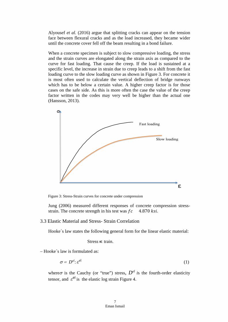
When a concrete specimen is subject to slow compressive loading, the stress and the strain curves are elongated along the strain axis as compared to the curve for fast loading. That cause the creep. If the load is sustained at a specific level, the increase in strain due to creep leads to a shift from the fast loading curve to the slow loading curve as shown in Figure 3. For concrete it is most often used to calculate the vertical deflection of bridge runways which has to be below a certain value. A higher creep factor is for those cases on the safe side. As this is more often the case the value of the creep factor written in the codes may very well be higher than the actual one (Hansson, 2013).
Figure 3: Stress-Strain curves for concrete under compression
Jung (2006) measured different responses of concrete compression stress- strain. The concrete strength in his test was 𝑓𝑓𝑓𝑓 = 4.870 𝑘𝑘𝑘𝑘𝑘𝑘.
3.3 Elastic Material and Stress- Strain Correlation
Hooke´s law states the following general form for the linear elastic material:
Stress ∝ train.
– Hooke´s law is formulated as:
σ = Del : εel (1)
whereσ is the Cauchy (or “true”) stress, Del is the fourth-order elasticity tensor, and εel is the elastic log strain Figure 4.

8 Eman Ismail
Figure 4: Stress-strain curve for a linear elastic material
The Concrete stress-strain relationship under compression is initially linear elastic until a micro-crack emerge, then the behavior becomes nonlinear. As shown in Figure 5 following an ultimate compressive strength the stress decreases with increasing strain (Saenz, 1964)
Figure 5: Concrete stress–strain relationship
Utilization of displacement formulations will be used to derivate the stiffness matrix of each element. Then the global stiffness matrix of the whole structure is formulated by the direct stiffness method. Finally, the global stiffness matrix and the obtained displacement boundary conditions
Young’s modulus, E
σ

9 Eman Ismail
as well as applied loads are determined and solved (Jawad, 2012).The formula in matrix equations expressed as follow:
[P] = [K] [U] (2)
Where:
[P] = nodal load vector
[K] = global stiffness matrix
[U] = nodal displacement vector
According to Timoshenko (1995), the displacement and stress at the center of the slab can be expressed in accordance with the following Equations:
ῳ1 = α1𝑞𝑞 𝑎𝑎4
𝐷𝐷 (3)
𝑀𝑀1 = 𝛽𝛽1𝑞𝑞 𝑎𝑎2 (4)
σ = 𝑀𝑀1𝑊𝑊
(5)
Since the bridge slab is subjected to predominantly a state of plane stress, Jung (2006) argues that the split-cylinder test is considered for determining the tensile strength of the concrete.

10 Eman Ismail

11 Eman Ismail
4. Methods and Implementation There are many methods and ways to investigate the responses of the slab with different angles and element sizes on distribution of stresses and displacements. The main focus of this thesis is on the 3D finite element method to perform the investigation and draw some conclusions.
3D finite element analyses provide opportunity for a more accurate investigation and study of the structure of skew slabs than the utilization of the more traditional design tools. According to Pacoste et al. (2102), there are number of critical factors which needed to be addressed to use the full strength of the finite element method. These factors are related either to the FE-modeling itself (geometry, support conditions, mesh density, etc.) or to the post processing of the obtained results (stress concentrations, displacement, choice of sections, etc). If the FEM is to be a useful tool in the design of reinforced concrete slab structures, accurate modeling is a prerequisite. Accurate modeling involves understanding the important relationships between the physical world and the analytical simulation (Deaton, 2005). Thus, it is important to investigate the effect of different element and angle sizes on the vertical displacements (deflections) and the stress load distribution.
Many finite element software packages have design code checks to allow for the elastic analysis and design to be carried out using one software package. For certain packages a design code based approach to moment redistribution and serviceability deflection checks could be included. Some analytical and experimental investigation using ABAQUS of different skew slabs will be conducted to trace load displacement and stress behavior of skewed RCC slabs up to failure.
4.1 Model Description 4.1.1 Geometry
As shown in Table 1 and Figure 6, the slab designed for this analysis had the following specifications:
Table 1: Used properties.
Property Value Length 4 m Width 2 m
Thickness 0.30 m Supported edge 2 sides
Free edge 2 sides

12 Eman Ismail
4 m
Figure 6: A skew plate with two free edges and two supported edges
Abaqus has three degrees of freedom for solid elements, i.e. ux, uy , uz. These three degrees of freedom at each node encompass two rotations and one translation. The two rotations are about the two in-plane axes, x and y, and the one translation is in the vertical, z, direction.
4.1.2 Material Properties
Linear elastic material properties are used such as Young’s Modulus and Poisson’s Ratio. The material properties must have the required level of accuracy to be able to validate its use in design methods. The material properties should also enable the ease of formulation for the design engineer. Young´s Modulus is an important parameter to be considered when designing and constructing a concrete slab. The safety-factor value for the concrete is often f 1.5 in the standards. Many studies and tests show that the Young’s modulus often is higher on the site than the predicted value stated on the standards. Hence, if a study vary the predicted value of 32 GPa, the range between 20 GPa and 50 GPa is good and of interest. The Poisson’s ratio is held constant and a value of 0.20 can be used for the concrete (Hayes and Shuvalov, 1998). Table 2 illustrates the following material properties.
Table 2: Material proprieties used in this thesis
Property Value Concrete grade C35/45*
Young´s modulus 33800000 kN/m2
Poisson’s ration 0.20 Load Pressure 12 kN/m2
* C35/45 is corresponds to K45 which is retrieved from the old Swedish standard BBK, as the cube strength is 45 MPa.
Abaqus provides a wide range of elements for different geometries, objectives and analysis types. According to Abaqus (2013:6.13 Manual/Documentation), an element is characterized by the following properties:
α Free edge
2m α
Free edge

13 Eman Ismail
• Family: Continuum, Shell, Membrane, Rigid, Beam, Truss, etc.
• Number of Nodes: Depends on element shape and its order of interpolation
• Degrees of Freedom per Node: Depends on the solution field of the analysis (Displacement, Rotation, etc.)
• The order of modeling space (1D, 2D and 3D).
• Integration: Reduced, full integration or hyper integration
• Generally, the use of quadrilateral and hexahedral elements is recommended for modeling of continuum solids.
• Solid element can provide first-order (linear) and second-order (quadratic) interpolation.
4.1.3 The Mesh; Load and the Boundary Conditions
Each element in Abaqus have a unique name which identifies the primary characteristics of the element such as C3D8R which stands for Continuum Stress/Displacement (C), 3-D, 8 is the number of node elements, Reduced integration. Abaqus offers three-dimensional hexahedral element such as C3D8R (8-node trilinear brick) and C3D20R (20-node quadratic brick). Application of quads and hex elements are generally recommended (Abaqus, 6.13 Manual/Documentation).
Based of the analysis of the 32 simulations (16 of the displacement and 16 of stress), the element type C3D20 with mesh size 0.05 mm and 0°skew angle was the best fit to conduct the main study and to compare the numerical results with the Timoshenko. The mesh size 0.05 shows that it require less computational and still give accurate solution.
Figure 7 shows the final mesh of the selected slab. A smaller mesh of hexahedral elements (C3D8R) is good because it usually provides a solution of equivalent accuracy at less cost (ABAQUS, 2013:6-13).

14 Eman Ismail
Figure 7: A mesh size 0.05 and 0° skew angle slab
The Displacement boundary conditions are needed to constrain the model to get a unique solution. To achieve this, the translations at the nodes U1, U2 and U3 are restrained in order to obtain a hinged joint. Figure 8 shows the used boundary condition U1 and U2 for left corner and U2 for right corner while U3 was used at the width sides of the plate.
Figure 8: Boundary conditions of the 0° skew angle slab
Left corner Right corner
U3
U2
U1

15 Eman Ismail
5. Results Table 3 summarize the result of the 16 experiments conducted by ABAQUS in order to identify the most suitable case to be further studied and analyzed in this thesis. A standard 0-angle slab was used as the basic model.
Table 3: Result of the 16 experiments conducted in this study
Mesh size Element type
Nr. of nodes
Nr. of elements
Displacement U3 (m)
Stress S. Max (MPa)
0.30 C3D8R 224 91 -0.0439033 27 C3D8 224 91 -0.0005750 1174 C3D20 740 91 -0.0005171 1584 C3D20R 740 91 -0.0005180 1585
0.10 C3D8R 3444 2400 -0.0005895 1188 C3D8 3444 2400 -0.0005192 1379 C3D20 12667 12667 -0.0005233 1591 C3D20R 12667 12667 -0.0005238 1590
0.05 C3D8R 23247 19200 -0.0005410 1361 C3D8 23247 19200 -0.0005224 1487 C3D20 88813 19200 -0.0005244 1590 C3D20R 88813 19200 -0.0005250 1590
0.03 C3D8R 100232 89110 -0.0005324 1441 C3D8 100232 89110 -0.0005238 1526 C3D20 389594 89110 -0.0005247 1590 C3D20R 389594 89110 -0.00052571 1591
Figure 9 illustrates the impact of different numbers of elements on displacement center while Figure 10 illustrates the impact of different Numbers of Elements on stress center.

16 Eman Ismail
Figure 9: Relation between Numbers of Elements& Displacement Variation in 0° Skew Angle
Figure 10: Relation between Numbers of Elements & Stress Variation in 0° Skew
Figures 9 and 10 reveal that element type C3D20 provides best result of the experiments. To calculate the element matrices, for instance, C3D20R.
Abaqus only uses 8 integration points compared to C3D20 which uses 27 integration points therefore its computation is almost 3.5 less costly.
Based of the analysis of the 32 experiments (16 of the displacement and 16 of stress), the element type C3D20 with mesh size 0.05 and skew angle 0° (Table 3) was the most fit model to conduct the main study and to compare the numerical result of it with the Timoshenko. Figure 11a shows the chosen displacement point at the center of the upper layer of the plate. Figure 11b shows the stress point at the center of the lower layer of the plate while figer 11 c shows the reaction force.

17 Eman Ismail
(a) The displacement at the upper layer
(b) The stress at the lower layer

18 Eman Ismail
(c) The reaction force
Figure 11: a, the displacement; b, the stress and c, the reaction force

19 Eman Ismail
6. Analysis and Discussion To validate the obtained FE results, a comparison with experimental results as shown by Timoshenko are necessary. The result of the basic model of this study is shown in Table 4.
Table 4: Finite element results
Skew Angle Displacement Stress (°) U3 (m) S. Max (MPa) 0 -0,0005244 1591 15 -0,0004793 1521 30 -0,0003678 1331 45 -0,0002390 1067 60 -0,0001312 776 75 -0.0000592 488
6.1 Displacement and Skew Angles
Figure 12 shows the impact of the skew angles 0°, 15°, 30°, 45°, 60°, 75° on the displacements.
Figure 12: Impact of skew angle on the displacement variation
6.2 Stress load distribution and skew angles
Figure 13 shows the impact of the skew angles 0°, 15°, 30°, 45°, 60°, 75°, on the Stress on the plates.

20 Eman Ismail
Figure 13: The Impact of skew angle on the stress
Figures 12 and 13 reveal that depends on the degree of skew angle and the element size, the stresses distribution and vertical displacements in the slab vary significantly from those in straight slab. It shows that the displacement decreases with the increase the angles while the stress increase with the decrease of the skew angle.
6.3 Reaction force (RF) and Skew angles
The moments and the reaction forces have been calculated with the finite element software with a linear-elastic model. The support reaction forces are those forces that the support has to provide to resist the loading. Figure 14 shows the relationship between the reaction forces and distances at each skew angle of 0°, 15°, 30°, 45°, 60° and 75° skew angles. The figure confirms that the Finite element modeling of a diaphragm is useful for identifying the load paths.
Figure 14 is also useful in assessing the force transfers among vertical elements of the seismic force resisting system.

21 Eman Ismail
(a) Skew angle 0°
(b) Skew angle 15°
(c) Skew angle 30°

22 Eman Ismail
(d) Skew angle 45°
(e) Skew angle 60°
(f) Skew angle 75°
Figure 14: Reaction force along different paths for different skew angles
Figure 15 shows all different skew angles to facilitate the comparison. The reaction forces are higher when the angle increases. The 0° skew angles, served here as a reference for comparison with skewed slabs.

23 Eman Ismail
Figure 15: Relationship between the reaction forces and Y distances of all different skew angles of this study
The reaction forces for the zero and 15° skewed slabs were less then 30 kN/m. Both meets at equilibrium of 8,3 kN/m force and 0.16 m distance.
6.4 A Comparison of experimental and analytical results with Timoshenko theory
The analytical model is based on the well–known Timoshenko theory. The Timoshenko theory assumes that the shear stress distribution across the cross section is supposed to be constant and linear. It is also assumed that the cross–sectional area is symmetric so that the neutral and centroidal axes coincide.
To validate the obtained FEA results, a comparison with experimental results obtained by Timoshenko. Table 5 illustrates the proprieties utilized for the comparison with Timoshenko. Table 6 is the results of Timoshenko experiments which shows the values of coefficients, displacements and stresses of uniformly loaded skewed plates.
Table 5: Proprieties utilized for the comparison with Timoshenko
Name Abbreviation Unit Value Young`s Modulus E kN/m2 33800000
Poisson`s ratio µ - 0,2 Thickness h m 0,3
Load q kN 12 Width A m 2

24 Eman Ismail
Flexural rigidity D m 79218,75 Section Modulus W m3 0,015
Table 6: Results according to Timoshenko theory
Skew angle 𝛂𝛂𝟏𝟏 𝛃𝛃𝟏𝟏 Displacement ῳ𝟏𝟏
Stress 𝛔𝛔
(°) max (m) max (kN/m2) 0 0,2240 0,508 0,0005429 1626 30 0,1302 0,367 0,0003155 1174 45 0,0869 0,296 0,0002106 947 60 0,0396 0,152 0,0000959 486
The comparison is shown in Table 7.
Table 7: Comparison to the analytical results of this study by Timoshenko
Skew Angle
(°)
Vertical Displacement
ῳ𝟏𝟏 (m) Timoshenko
Vertical Displacement
ῳ𝟏𝟏 (m) this study
Stress
𝝈𝝈 (MPa) Timoshenko
Stress
𝝈𝝈 (MPa) this study
0 0,0005429 0,0005244 1626 1591 30 0,0003155 0,0003678 1174 1331 45 0,0002106 0,0002390 947 1067 60 0,0000959 0,0001312 486 776

25 Eman Ismail
7. Conclusions The main conclusions of the comparison between Timoshenko results and the FEA results of this study regarding the changes in vertical displacements as response to the changes of the skew angles this study can be illustrated by Figure 15. The only significant different is related to the skew angle 60°.
Figure 16: Comparison between displacements for different skew angle of slabs
The main conclusions of the comparison between Timoshenko results and the FEM results of this study regarding the changes in stress distributions as response to the changes of the skew angles this study can be illustrated by Figure 17. The only significant different is related to the skew angle 60°.
Figure 17: Comparison between stress distributions for different skew angle of slabs
This study shows interesting results. There is very slight changing in the vertical displacements and stress distribution between the results obtained by this study and the results obtained by Timoshenko regarding the plates with skew of 0°, 30° and 45°. But the differences is large concerning the plate of 60 skew. Regarding the stress distribution, the Timoshenko study shows observed higher stress at the basic case with 0° skew, while our study shows higher stress than Timoshenko in case of the other skewed plates, i.e 30°,

26 Eman Ismail
45° and 60°. In general, the maximum deflection for skewed slabs decreases with the increase in skew angle for all aspect ratios and at 60° there was a reduction of 85% in Timoshenko study and 75% when compared to right slab in our study. A similar trend was observed in study conducted by Ramesh and Kumar (2017).

27 Eman Ismail
References ABAQUS (2013). User’s Manual, Version 6.13, Hibbitt, Karls-son & Sorensen, Inc., Pawtucket, Rhode Island, USA. Abozaid, LA., Hassan, A., Abouelezz, A.Y., and Abdel- Hafez, L. M. (2014). Nonlinear Behaviour of a Skew Slab Bridge under Traffic Loads- World Applied Sciences Journal, Vol. 30, No. 11, pp. 1479-93 Alyousef, R., Topper, T., and Al-Mayah, A. (2016). Effect of the thickness of concrete cover on the fatigue bond strength of GFRP wrapped and non-wrapped reinforced concrete beams containing a lap splice. Structures, Research Journal of The Institution of Structural Engineers. Vol. 6, pp. 1-8 Anusreebai S.K. and Krishnachandran V.N. (2016). Effect of Skew Angle on the Behaviour of Skew Slab under Uniformly Distributed Load. International Journal for Research in Applied Science & Engineering Technology (IJRASET), Vol 4, No.VIII, August, pp-601-8 Bartha, E. B., & Wu, H. (2006). Efficient nonlinear finite element modeling of slab on steel stringer bridges, Finite Elements in Analysis and Design 42, 1304 – 1313 Bobade, S.D., and Varghese, V. (2016). Parametric Study of Skew Angle on Box Girder Bridge Deck. International Journal of Engineering Science & Research Technology, Vo.5, No. 7,July, pp. 142-153 Chan, T. H. T. and Chan, J. H. F. (1999) The Use of Eccentric Beam Elements in the Analysis of Slab-on-Girder Bridges, Structural Engineering and Mechanics, Vol. 8, No. 1, pp. 85- 102. Deaton, J.B. (2005). A Finite element approach to reinforced concrete slab design. School of Civil and Environmental Engineering Georgia Institute of Technology Dutt, A. (2015), Effect of Mesh Size on Finite Element Analysis of Beam, SSRG International Journal of Mechanical Engineering (SSRG-IJME) – vol. No. 12, pp.8-10 Fu, C. C., Tim L. Briner and Getaneh, T. (2012). Theoretical and Field Experimental Evaluation of Skewed Modular Slab Bridges. Report No. MD-12-SP109B4N, Maryland State Highway Administration Grassl, P., Xenos, D., Nystrom, U., Rempling, R., and Gylltoft K. (2013). CDPM2: A damage-plasticity approach to modelling the failure of concrete. International Journal of Solids and Structures,

28 Eman Ismail
Vol. 50, pp. 3805–3816 Jawad, S. (2012). Investigation of Load Distribution Factors for Simply-Supported Composite Multiple Box Girder Bridges. A Thesis
Presented to Ryerson University In Partial Fulfillment of the Requirement for the Degree of Master of Applied Science In the Program of Civil Engineering Toronto, Ontario, Canada Jung, Y. (2006). Investigation into Bamboo as Reinforcement in Concrete. Master’s Thesis. The University of Texas at Arlington. [Online] Available: http://gradworks.umi.com//14/35/1435983.html (July 14, 2016) Hansson, D. (2013). Nonlinear FEM load bearing capacity assessment of a concrete bridge subjected to support settlements- Case of a continuous slab bridge with angled supports. Master Thesis 398, 2013 at Royal Institute of Technology (KTH), School of Architecture and the Built Environment, Department of Civil and Architectural Engineering- Division of Structural Engineering and Bridges, Stockholm, Sweden. Hayes, M., and Shuvalov, A. (1998) "On the Extreme Values of Young's Modulus, the Shear Modulus, and Poisson's Ratio for Cubic Materials", ASME J. Appl. Mech., Vol. 65, pp.786-787. Hrennikoff, A. (1941). Solution of problems of elasticity by framework method. American Society of Mechanical Engineers -- Transactions -- Journal of Applied Mechanics, 8(4), 169--175. Huang, H., Shenton, H. W., and Chajes, M. J. (2004). “Load Distribution for a Highly Skewed Bridge: Testing and Analysis.” Journal of Bridge Engineering, 9(6), 558-562. Kar, A., Khatri, V., Maiti, P. R., Singh, P. K. (2012). Study on Effect of Skew Angle in Skew Bridges. International Journal of Engineering Research and Development, Volume 2, Issue 12 (August 2012), PP. 13-18 13 Koppitz, R., Keller, T., & Kenel, A. (2013). Punching shear strengthening of reinforced concrete flat slabs with carbon-fiber rienforced polymer reinforcement. Paper presented at the FRPRCS-11, Guimaraes, Portug Koppitz, R., Keller, T., & Kenel, A. (2013). Punching shear strengthening of reinforced concreteflat slabs with carbon-fiber reinforced polymer reinforcement. Paper presented at the FRPRCS-11, Guimaraes, Portugal Labibzadeh, M. (2015). Damaged-plasticity concrete model identification for prediction the effects of CFRPs on strengthening the weakened RC two-way slabs with central, lateral and corner openings. Int. J. of Structural Engineering, Vol.6, No.3, pp.240 – 268 Menassa, C., Mabsout, M., Tarhini, K., and Frederick, G. (2007). “Influence of Skew Angle on Reinforce Concrete Slab Bridges.”

29 Eman Ismail
Journal of Bridge Engineering, 12(2), 205-214. Minalu, K. K. (2010). Finite Element Modelling of Skew Girder Slab Bridges. Master Thesis in Science, Faculty of Civil Engineering and Geosciences Technical University of Delft, August Pacoste C., Plos M., Johansson M., (2012). Recommendations for finite element analysis for the design of reinforced concrete slabs. Royal Institute of Technology, Stockholm, Sweden. Théoret, P., Massicotte, B., and Conciatori, D. (2012). Analysis and Design of Straight and Skewed Slab Bridges, Journal of Bridge Engineering, Vol. 17, No. 2, March 1. Ramesh, L and Kumar (2017), Finite Element Modeling of Reinforcemented Cemetn Concrete Skew Bridge and Daynamic Analysis. Anveshana´s International Journal of Research and Applied Sciences, Vol. 2, No. 1, January, pp. 210-215Roll, F., & Aneja, I. (1966). Model tests of box-beam highway bridges with cantilevered deck slabs. ASCE Transportation Engineering Conference, Oct 17- Oct 21, 395 (33p). Adic, D., and Deumic, E. (2011). Finita element analysen av sammankopplade C3C solida betongblock utan fog / FE analysis of interlocking C3C solid concrete blocks without casting. Master Thesis, Linnaeus University, Sweden, School of Engineering Department of Civil Engineering. Saenz, L. (1964) Discussion equation for the stress - strain curve of concrete, By Desayi P, Krishnan S, ACI J, 1964; 61, 1229– 35.Sargious, M. and Tadros, G. (1970). “Stresses in prestressed concrete stepped cantilevers under concentrated loads”, Proceedings, Sixth Congress of the FIP, Prague, Fédération Internationale de la Précontrainte, Paris, France. Sindhu, B.V., Ashwin, K.N., Dattatreya, J.K., and Dinesh, S. V. (2013). Effect of Skew Angle on Static Behviour of Reinforced Concrete Slab Bridge Decks. International Journal of Research in Engineering and Technology , Nov-2013, Available @ http://www.ijret.org 50 Sharma M (2011) "Finite Element Modelling of Reinforced Concrete Skew Slab" ME (Structures) Thesis, Thapar University Patiala, Punjab. Sujith. Jiji, A., Tennu, S. (2015). Comparative Study on the Behaviour of T Beam Skew Bridges. International Journal of Innovative Research in Science, Engineering and Technology . Vol. 4, Issue 9, pp.8287- 8295
Timoshenko, S. and Woinowsky-Krieger (1959). Theory of Plates and Shells, McGraw-Hill

30 Eman Ismail

Faculty of Technology 351 95 Växjö, Sweden Telephone: +46 772-28 80 00, fax +46 470-832 17