distributed rt systems introduction itv multiprogramming and real-time systems anders p. ravn...
Post on 21-Dec-2015
219 views
TRANSCRIPT
Distributed RT SystemsIntroduction
ITV Multiprogramming and Real-Time SystemsAnders P. Ravn
Aalborg UniversityApril 2009

Prerequisites
• Understanding of Real-Time Systems for monoprocessor systems
• Understanding of Distributed Systems
Aims
• Understanding the issues in combining RT and Distributed Architectures
• Ability to model and analyse such systems
• To stimulate research interest

What is a real-time system?
• A real-time system is a computerized system that must respond to externally generated input within specified time bounds
• The computer is a component in a larger engineering system -
EMBEDDED COMPUTER SYSTEM
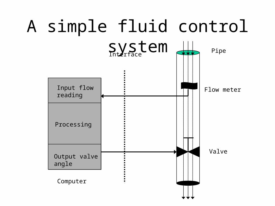
A simple fluid control systemPipe
Flow meter
Valve
Interface
Computer
Input flowreading
Processing
Output valveangle
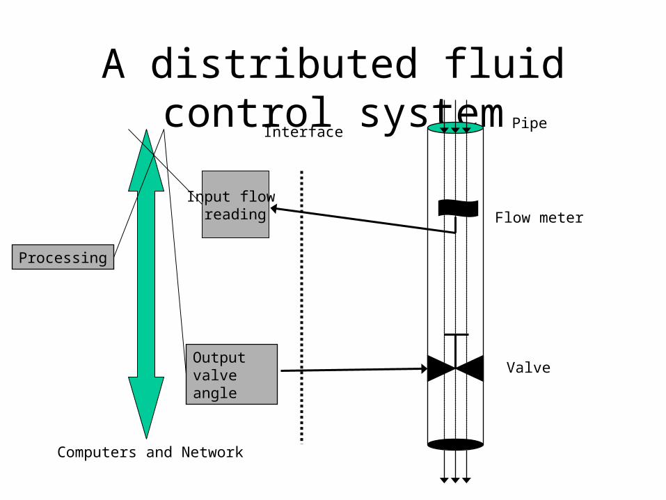
A distributed fluid control systemPipe
Flow meter
Valve
Interface
Computers and Network
Processing
Output valveangle
Input flow reading

The Periodic Control Task
LOOP wait_until(t) read_sensor;
send reading;t = t+T;
END
Tightly Coupled : OR Distributed:
LOOP
get reading;
compute;
send setting
END
LOOP
get setting
write_actuator;
END
LOOP
wait_until(t)
read_sensor;
compute;
write_actuator;
t = t+T;
END

The R-T Constraints
Have not changed !

Terminology• Hard real-time
• Soft real-time
• Firm real-time
Val
ue o
f re
spon
se
TimeD
TimeD
D may be missed occasionally

RTS DesignEssentially: Specification of a collection of periodic and sporadic tasks.
Tasks may share resources, but must not block explicitly.
Formalisms:• UML-RT• RT- HOOD
NEW: •Selection and Analysis of networkOR •Selection of a Distributed R-T platform
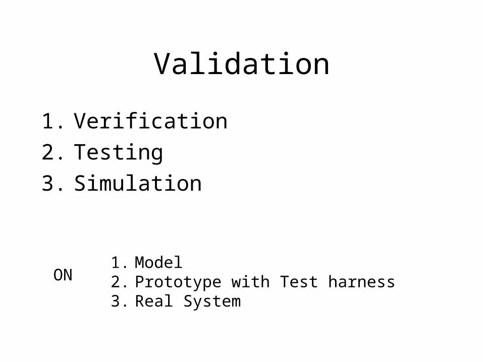
Validation
1. Verification
2. Testing
3. Simulation
ON1. Model2. Prototype with Test harness3. Real System

Characteristics of a RTS
• Timing Constraints
• Dependability Requirements
• Concurrent control of separate components
• Facilities to interact with special purpose hardware
Have not changed !
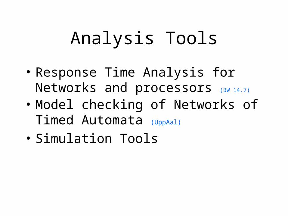
Analysis Tools
• Response Time Analysis for Networks and processors (BW 14.7)
• Model checking of Networks of Timed Automata (UppAal)
• Simulation Tools
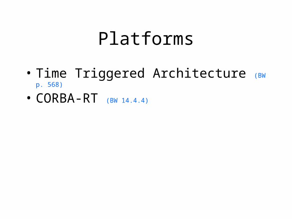
Platforms
• Time Triggered Architecture (BW p. 568)
• CORBA-RT (BW 14.4.4)

Distributed Algorithms
• Clock Synchronization (BW 14.6.2)
• Fault Tolerance (BW 14.5)

Networks
• CAN
• TT-CAN
• TTP/C Protocol
• ARINC 629
• WorldFIP
• PROFIBUS
• …

CAN• initial target automotive applications• a multi-master architecture • a broadcast shared bus,• the transmission medium is usually a twisted pair cable• network maximum length depends on the data rate (e.g. 40m @ 1
Mbps; 1300m @ 50 Kbps)• The arbitration uses a CSMA non-destructive bit-wise protocol in
which the controller transmitting the message with lowest identifier wins access to the medium and continues transmission.
• The remaining controllers detect a collision back off and retry again• The traffic scheduling at the bus access level is thus based on fixed
priorities. applications. • The addressing is indirect and based on the identifiers, too. • The CAN protocol does not specify an application layer.

TTP/C Protocol
• a fault-tolerance oriented communication protocol• clock synchronization• membership service• fast error detection and consistency checks• . A network consists of a set of communicating nodes connected by a
replicated network• . A node comprises a host computer and a TTP/C communication controller. • The medium access control is based on TDMA with bus time divided into
slots, each statically assigned to one node. In each slot each node transmits one frame. The frame cycle is called a
• Messages are piggybacked within the frames transmitted by each node. • The protocol defines 4 transmission speed classes ( 500Kbps, 1Mbps, 2Mbps
and more recently 25Mbps) • an application layer that delivers configuration and messaging services.

Middleware
• Masks system and network heterogeneity
• Hides complexity of distributed systems
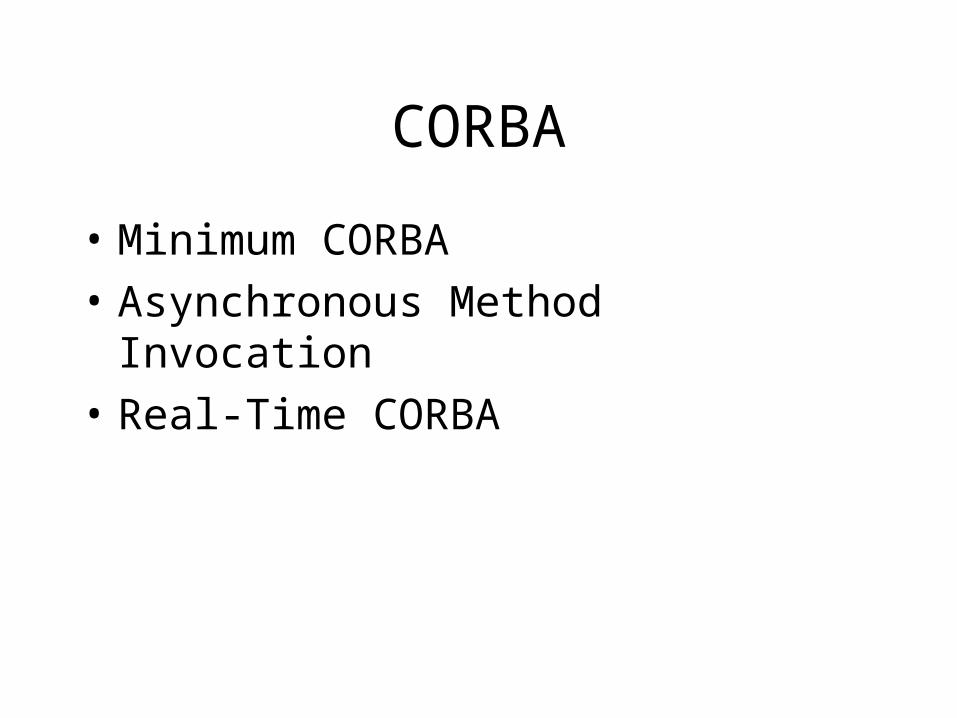
CORBA
• Minimum CORBA
• Asynchronous Method Invocation
• Real-Time CORBA

Real Time CORBA
• Policies and mechanisms for specifying end-to-end application QoS requirements.
• QoS enforcement from real-time operating systems and networks.
• Optimized real-time communication protocols• Optimized real-time request demultiplexing and
dispatching.• Optimized memory management.• Optimized presentation layer
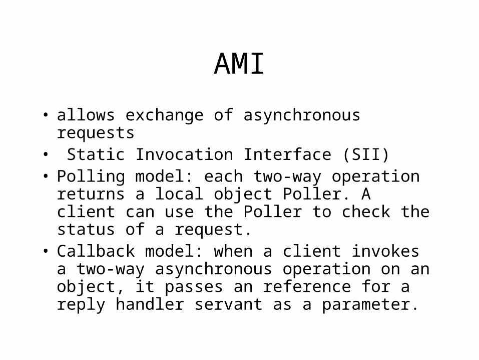
AMI
• allows exchange of asynchronous requests• Static Invocation Interface (SII) • Polling model: each two-way operation returns a
local object Poller. A client can use the Poller to check the status of a request.
• Callback model: when a client invokes a two-way asynchronous operation on an object, it passes an reference for a reply handler servant as a parameter.
Message Oriented Middleware
• Java Message Service (JMS)
• Data Distribution Service for Real-Time systems (DDS)

The CAN bus

Physical Layer
• Serial bus
• Electrical properties and timing see:http://www.semiconductors.bosch.de/en/20/can/3-literature.asp
• Dominant and Recessive encoding:
dominant is logical 0
recessive is logical 1
simultanous transmission gives logical AND

Frame FormatField name Length (bits) Purpose
Start-of-frame 1 Dominant 0
Identifier 11 Sender id
RTR 1 Dominant 0
Identifier extension 1 Dominant 0
Reserved 1
Data length (bytes) 4 0-8
Data field 0 - 64
CRC15 15
CRC delimiter 1 Recessive 1
ACK 1
ACK delimiter 1 Recessive 1
End-of-frame 7 Recessive 1

Medium Access Control
Hanz p. 6

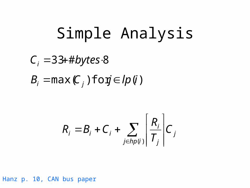
Simple Analysis
• One process per processor• No error handling
jihpj j
iiii C
T
RCBR
)(
Hanz p. 10, CAN bus paper
Simple Analysis
jihpj j
iiii C
T
RCBR
)(
Hanz p. 10, CAN bus paper
8#33 bytesCi
)( for )max( ilpjCB ji

Extended Analysis
j in hp(i)
Remarks
• There is no easy way of finding an optimal assignment for the extended case!
• The formulas are too pessimistic M, Cross-interference
• Experimental validation.

FTT-CAN
• Static versus Dynamic Traffic Scheduling
• Event versus Time Triggered Communication
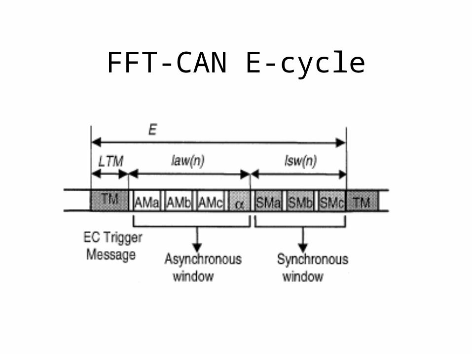
FFT-CAN E-cycle

Overhead

Synchronous Messaging System
SRT entries:
• DLC – data length
• C - max transmission time
• Ph - relative phase
• P - Period measured in E’s (T)
• D - Deadline
• Pr - fixed priority
For Each E-cycle
• A synchronous schedule is broadcast with the EC-Trigger Message
• Plan based scheduling
• On-line scheduling

Schedulability Analysis
Blocking free non-preemptive scheduling
RM:
EDF:
Asynchronous Messaging System
ART entries:
• DLC – data length
• C - max transmission time
• MIT - min interarrival time in E’s
• D - Deadline
• Pr - fixed priority

Schedulability Analysis
Remarks
• Transmission errors not treated
• Master selection not treated