distributed i/os simatic et 200 - tekhar.comtekhar.com/programma/siemens/simatic/controllers/... ·...
TRANSCRIPT
Distributed I/OsSIMATIC ET 200
Siemens IK PI News . July 2005
6/2 SIMATIC ET 200S6/2 Analog electronics modules6/5 Technology modules6/5 1 POS U positioning module6/7 ET 200S – Software6/7 STARTER drive/commissioning
software
6/8 SIMATIC ET 200iSP6/8 Introduction6/11 IM 152-1 interface module 6/13 ET 200iSP digital electronics modules
and terminal modules6/16 ET 200iSP analog electronics modules
and terminal modules6/22 ET 200iSP reserve modules and
terminal modules6/24 ET 200iSP power supply unit
6/25 SIMATIC ET 200pro 6/25 Introduction6/27 IM 154-1 and IM 154-2
interface modules 6/30 IM 154-4 PN interface modules6/31 EM 141 and EM 142
digital expansion modules6/35 EM 144 and EM 145
analog expansion modules6/37 PM-E power module6/38 ET 200pro motor starters6/42 ET 200pro maintenance switch
module6/43 Safety local Module6/46 Accessories for ET 200pro
motor starters

Siemens IK PI News · July 20056/2
SIMATIC ET 200 distributed I/Os
Analog electronics modules
ET 200S
6
Overview
• Analog inputs and outputs for the ET 200S• Can be connected to the TM-E terminal module with automatic
coding• High-feature versions with enhanced accuracy and resolution
- 2 AI RTD High Feature• High-speed versions for high-speed analog value acquisition
- 2 AI High Speed with enhanced characteristics• Module replacement during operation and when live
(hot swapping)
Note:For selection of suitable TM-E terminal modules, please use the configuring tools.
Technical specifications
Analog input 6ES7 134-4GD00-0AB0
Voltages and currents
Load voltage L+- Rated value (DC) 24 V; from power module- Reverse polarity protection Yes
Power supply of measuring transducers
- Available Yes; automatically set- Short-circuit proof Yes; automatically set
Current consumption • from load voltage L+ (no load),
max.125 mA
• from backplane bus 3.3 V DC, max.
10 mA
• Power dissipation, typical 0.6 W
Address area
Address space per module- Address space per module,
max.8 byte
Clock synchronism
• Clock synchronous operation No; automatically set
Analog inputs
• Number of analog inputs 4
• Length of cable shielded, max 200 m
• Permiss. input voltage for voltage input (destr. limit), max.
-
• Perm. input volt. for the current input (destr. lim.), max.
30 mA
• Measuring current -
• Cycle time (all channels) 40 ms; deactivation of the channels brings no reduction
• Technical unit for temperature measurement can be set
-
Input ranges (rated values), voltages
• Voltage -
• 1 to +5 V -
• -10 V to +10 V -
• -5 V to +5 V -
• -80 mV to +80 mV -
• Input resistance (-80 mV to +80 mV)
-
Input ranges (rated values), currents
• Current Yes
• Input resistance (0 to 20 mA) -
• -20 to +20 mA No
• 4 to 20 mA Yes

Siemens IK PI News · July 2005 6/3
SIMATIC ET 200 distributed I/OsET 200S
Analog electronics modules
6
Technical specifications (continued)
Analog input 6ES7 134-4GD00-0AB0
Analog value formation • Measuring principle -
Integration and conversion time/triggering per channel• with over-range (bits incl. sign),
max13 bit; 4 to 20 mA: 13 bit
• Integration time parameterizable Yes; automatically set• Integration time, ms 16.7 or 20• Interference voltage suppr. for in-
terference frequency f1 in Hz60 / 50 Hz
• Conversion time (per channel) -
Smoothing of measured values• Parameterizable Yes; in 4 steps• None Yes; 1x cycle time• Weak Yes; 4x cycle time• Medium Yes; 16x cycle time• Strong Yes; 32x cycle time
Sensor Sensing element connection -• for voltage measurement -• for current measurement,
as 2-wire measuring transducer -
• for resistance measurement, with 2-wire connection
-
• for resistance measurement, with 3-wire connection
-
• for resistance measurement, with 4-wire connection
-
• Load of the 2-wire transducer, max.
750 Ω
Error/accuracies • Linearity error
(relative to the input range)+/- 0,01 %
• Temperature error (relative to the input range)
+/- 0,003 %/K
• Crosstalk between the inputs, min. -50 dB• Repeatab. in the settled state
at 25 °C (rel. to output range)+/- 0,05 %
Operational limit in the entire temperature range• relative to the input range, voltage -• relative to the input range, current +/- 0,4 %• relative to the input range,
resistance thermometer-
Basic error limit (operational limit at 25 °C)• relative to the input range, voltage -• relative to the input range, current +/- 0,3 %• relative to the input range,
resistance thermometer-
Interference voltage suppression for f = n x (fl +/- 1 %)• Series-mode interference
(peak value of interference < rated value)
70 dB
• Common-mode interference (USS < 2.5 V) , min.
-
Analog input 6ES7 134-4GD00-0AB0
Parameters • Comment -• Wire break diagnostics Yes• Measurement type/Measuring
rangeYes
• Interference frequency suppres-sion
-
• Group diagnostics Yes• Reference junction slots 1 to 8 -• Overflow/underflow Yes• Reference junction -• Reference junction number -• Unit -
Status information/ interrupts/ diagnostics
Interrupts- Process interrupt -
Diagnostics• Diagnostic functions Yes; automatically set• Diagnostic information can be
read out-
• Wire break Yes• Group error Yes• Overflow/underflow Yes
Diagnostic display LED• Group fault SF (red) Yes
Insulation • Insulation tested with 500 V DC
Galvanic isolation Analog output functions• between the channels No• between the channels and
the backplane busYes
• between the channels and the load voltage L+
No
Permissible potential difference • between the inputs (UCM) -• between the inputs and MANA
(UCM)-
• between MANA and Minternal (UISO)
-
Dimensions and weight • Weight, approx. 40 g• Width 15 mm• Height 81 mm• Depth 52 mm• Module width, max. 15 mm
Siemens IK PI News · July 20056/4
SIMATIC ET 200 distributed I/Os
Analog electronics modules
ET 200S
6
Ordering data Order No. Order No.
A) Subject to export regulations: AL: N and ECCN: EAR99H
Analog input modules A
Ordering unit 1 item
• 2 AI U Standard 6ES7 134-4FB01-0AB0
• 2 AI U High Speed 6ES7 134-4FB51-0AB0
• 2 AI U High Feature 6ES7 134-4LB00-0AB0
• 2 AI I Standard 2-wire 6ES7 134-4GB01-0AB0
• 2 AI I High Speed 2-wire 6ES7 134-4GB51-0AB0
• 2 AI I Standard 4-wire 6ES7 134-4GB11-0AB0
• 2 AI I High Speed 4-wire 6ES7 134-4GB61-0AB0
• 2 AI I High Feature 2-wire/4-wire (15 bits + sign)
6ES7 134-4MB00-0AB0
• 2 AI RTD standard 6ES7 134-4JB50-0AB0
• 2 AI TC standard 6ES7 134-4JB00-0AB0
• 2 AI RTD High Feature 6ES7 134-4NB50-0AB0
• 2 AI TC High Feature 6ES7 134-4NB00-0AB0
• 4 AI Standard 2-wire 6ES7 134-4GD00-0AB0
Analog output modules A
Ordering unit 1 item
• 2 AO U Standard 6ES7 135-4FB01-0AB0
• 2 AO U High Feature 6ES7 135-4LB01-0AB0
• 2 AO I Standard 6ES7 135-4GB01-0AB0
• 2 AO I High Feature 6ES7 135-4MB01-0AB0
NEW
Accessories for labeling
DIN A4 labeling sheet
• Petrol 6ES7 193-4BH00-0AA0
• Red 6ES7 193-4BD00-0AA0
• Yellow 6ES7 193-4BB00-0AA0
• Light beige 6ES7 193-4BA00-0AA0
Accessories for system-integrated shield connection
Shield connection element 6ES7 193-4GA00-0AA0Ordering unit 5 itemsFor plugging into TM-E and TM-P
Shield clamps 6ES7 193-4GB00-0AA0Ordering unit 5 itemsFor 3 × 10 mm busbars
Grounding terminal 8WA2 868Ordering unit 1 itemFor cable cross-sections up to 25 mm2
3 × 10 mm busbars 8WA2 842Ordering unit 1 item

Siemens IK PI News · July 2005 6/5
SIMATIC ET 200 distributed I/OsET 200S — Technology modules
1 POS U positioning module
6
Overview
• Positioning module 1 POS U is a single-channel positioning module for ET 200S for the positioning of positioning and oper-ational axes
• For controlled positioning using digital outputs according to the rapid/creep feed principle
• With actual position value sensing for - Incremental encoders with 5 V difference signals or 24 V
signals, or for SSI encoders- Proportioning mode
(single evaluation of encoder signal A only)• Reference-point approach, actual value setting • Parameter change during operation
- Reversing difference - Shutdown difference
• Functions - Inching:
Direct application of control signals by the master - Traversing:
Absolute or relative - Axes:
For linear and rotary axes - Latch function:
Saves the current value by setting a digital input
Note
Siemens is offering position measuring systems and pre-assembled connecting cables for counting and positioning functions under SIMODRIVE Sensor or Motion Connect 500.

Siemens IK PI News · July 20056/6
SIMATIC ET 200 distributed I/Os
1 POS U positioning module
ET 200S — Technology modules
6
TechnicaTechnical specifications
Ordering data Order No.
1 POS U positioning module 6ES7 138-4DL00-0AB0
Voltages and currents Load voltage L+
- Rated value (DC) 24 V- Reverse polarity protection Yes- permissible range,
lower limit (DC)20.4 V
- permissible range, upper limit (DC)
28.8 V
Current consumption • from load voltage L+ (no load),
max.50 mA
• from backplane bus 5 V DC, max. 10 mA• Power dissipation, typ. 2 W
Digital inputs Length of cable
- Length of cable unshielded, max 50 m• Input characteristic to comply
with IEC 1131, Type 2Yes
Input voltage- Rated value, DC 24 V- for signal 0 -30 V to 5 V- for signal 1 11 V to 30 V
Input current- for 0 signal, max (permissible
closed-circuit current)2 mA
- for 1 signal, typical 9 mA
Digital outputs
• Length of cable shielded, max. 1,000 m
• Length of cable unshielded, max. 600 m
• Short-circuit protection of the output
Yes
- response threshold, typ. 0.7 A to 1.8 A
• Restriction of the inductive tran-sient voltage to
Yes; L+ -(55 ... 60 V)
• Lamp load, max. 5 W
• Driving a digital input Yes
Output voltage- Rated value (DC) 24 V- for 0 signal (DC), max. 3 V- for signal 1, min. L+ -1 V
Output current- for 1 signal permissible range
for 0 to 60 °C, min.7 mA
- for 1 signal permissible range for 0 to 60 °C, max.
600 mA
- for 0 signal residual current, max. 0.3 mA
Switching frequency- at resistive load, max. 100 Hz- at inductive load, max. 2 Hz- at lamp load, max. 10 Hz
1 POS U positioning module 6ES7 138-4DL00-0AB0
Sensor supply 5 V - sensor supply
- 5 V Yes- Short-circuit protection Yes- Output current, max. 500 mA
24 V - sensor supply- 24 V Yes- Short-circuit protection Yes- Output current, max. 500 mA
Absolute encoder (SSI) - sensor supply
- Absolute encoder (SSI) Yes- Output voltage L+ -0.8 V- Output current, max. 500 mA- Short-circuit protection Yes
Sensor Connectable encoders
- Absolute encoder (SSI) Yes- 2-wire BEROS Yes; Type 2
Incremental encoder (symmetrical)• Encoder signal 5 V
- signal level according to RS 422
Absolute encoder (SSI)• Updating of the encoder value
- Monoflop time 64 ms
Status information/ interrupts/ diagnostics Diagnostic display LED
- Actual value decreasing DN (green)
Yes
- Actual value increasing UP (green)
Yes
- Positioning mode POS (green) Yes- Group fault SF (red) Yes- Status display digital input
(green)Yes
Potentials/ electrical isolation • between backplane bus and all
other circuit componentsYes
• between the channels and the backplane bus
Yes
Dimensions and weight • Weight, approx. 65 g• Width 30 mm• Height 81 mm• Depth 52 mm
Positioning module 1 POS U 6ES7 138-4DL00-0AB0
Single-channel positioning module for ET 200S for positioning the adjustment and operation axes

Siemens IK PI News · July 2005 6/7
SIMATIC ET 200 distributed I/OsET 200 — Software
STARTER drive/commissioning software
6
Overview
The easy-to-use STARTER drive/commissioning software can be used to• start up,• optimize and• diagnose.
This software can be operated either as a stand-alone PC appli-cation or can be integrated into the SCOUT engineering system (SIMOTION). The basic functions and handling are the same in both cases.
In addition to the SINAMICS drives, the current version of STARTER also supports MICROMASTER 4 drives and frequency converters for the decentralized SIMATIC ET 200S FC periphery.
The project wizards can be used to create the drives within the structure of the project tree.
First-time users are supported by a solution-based dialog menu, with a standard graphics-based display maximizing clarity when setting the drive parameters.
First commissioning is guided by wizards, which make all the basic settings in the drive. This enables a drive to be up and running after only setting a small number of parameters within the drive configuration process.
The individual settings required are made using graphics-based parameterization screenforms, which also display the mode of operation.
Examples of individual settings that can be made include:• terminals• bus interface• setpoint channel (e.g. fixed setpoints)• speed control (e.g. ramp-function generator, limits)• BICO interconnections• diagnostics
Experts can gain rapid access to the individual parameters via the Expert List and do not have to navigate dialogs. In addition, the following functions are available for optimization purposes:• self-optimization• trace
Diagnostics functions provide information about:• control/status words• parameter status• operating conditions• communication states
Performance • Easy to use: only a small number of settings need to be made
for successful first commissioning: axis turning• Solution-based dialog-based user guidance simplifies com-
missioning.• Self-optimization functions reduce manual effort for optimiza-
tion.• The built-in trace function provides optimum support during
commissioning, optimization and troubleshooting.
Minimum hardware and software requirements • PG or PC with Pentium™ II 400 MHz (Windows™ NT/2000)• Pentium™ III 500 MHz (Windows™ XP)• 256 MB RAM• Monitor resolution 1024 × 768 pixels• Windows™ NT 4.0 SP6, 2000 SP3, XP Professional SP1• Microsoft Internet Explorer 5.01
For the communication between PG/PC and the Control Unit CU320 a PROFIBUS communication module and a connection cable are required.
E. g. PROFIBUS CP 5512 communications module (PCMCIA card, type 2 + adapter with 9-pole SUB-D socket for connection to PROFIBUS.
For MS Windows 2000/XP Professional and PCMCIA 32)Order No.: 6GK1551-2AA00and connection cable between CP 5512 and PROFIBUSOrder No.: 6ES7901-4BD00-0XA0
Ordering data Order No.
B) Subject to export regulations: AL: N and ECCN: EAR99S
STARTER commissioning tool for SINAMICS and MICROMASTERGerman/English
B 6SL3 072-0AA00-0AG0
Siemens IK PI News · July 20056/8
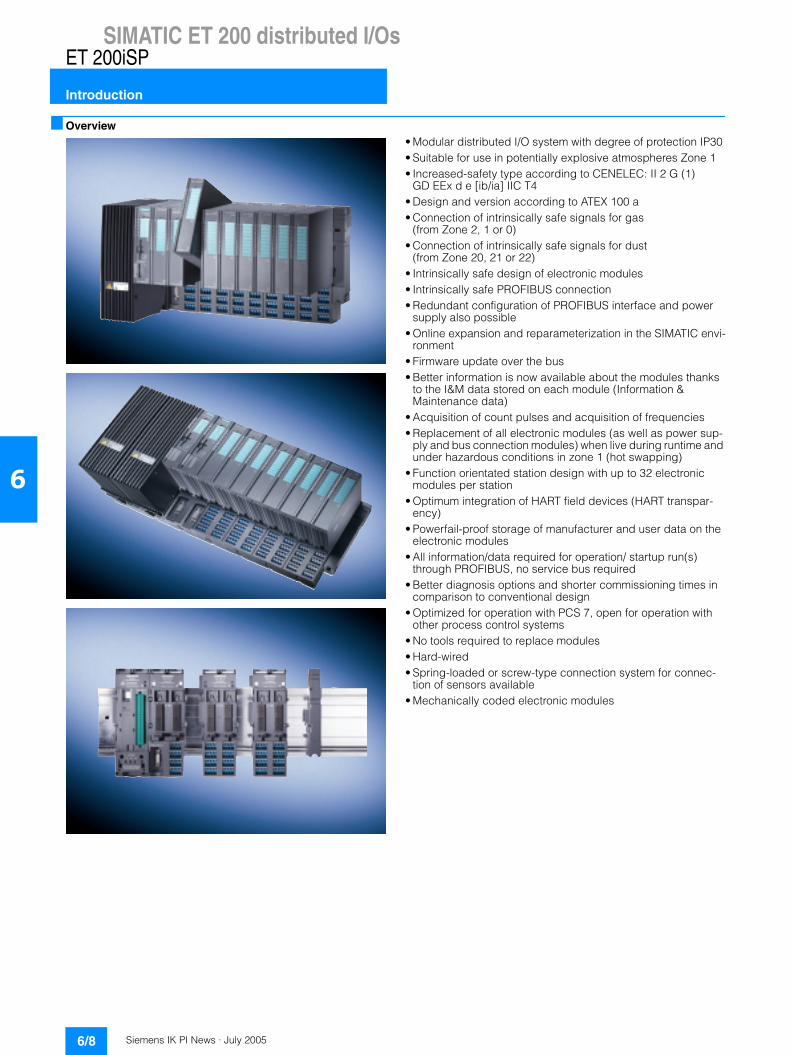
SIMATIC ET 200 distributed I/Os
Introduction
ET 200iSP
6
Overview
• Modular distributed I/O system with degree of protection IP30 • Suitable for use in potentially explosive atmospheres Zone 1• Increased-safety type according to CENELEC: II 2 G (1)
GD EEx d e [ib/ia] IIC T4• Design and version according to ATEX 100 a• Connection of intrinsically safe signals for gas
(from Zone 2, 1 or 0)• Connection of intrinsically safe signals for dust
(from Zone 20, 21 or 22)• Intrinsically safe design of electronic modules• Intrinsically safe PROFIBUS connection• Redundant configuration of PROFIBUS interface and power
supply also possible• Online expansion and reparameterization in the SIMATIC envi-
ronment• Firmware update over the bus• Better information is now available about the modules thanks
to the I&M data stored on each module (Information & Maintenance data)
• Acquisition of count pulses and acquisition of frequencies• Replacement of all electronic modules (as well as power sup-
ply and bus connection modules) when live during runtime and under hazardous conditions in zone 1 (hot swapping)
• Function orientated station design with up to 32 electronic modules per station
• Optimum integration of HART field devices (HART transpar-ency)
• Powerfail-proof storage of manufacturer and user data on the electronic modules
• All information/data required for operation/ startup run(s) through PROFIBUS, no service bus required
• Better diagnosis options and shorter commissioning times in comparison to conventional design
• Optimized for operation with PCS 7, open for operation with other process control systems
• No tools required to replace modules • Hard-wired • Spring-loaded or screw-type connection system for connec-
tion of sensors available • Mechanically coded electronic modules
Siemens IK PI News · July 2005 6/9
SIMATIC ET 200 distributed I/OsET 200iSP
Introduction
6
Application
The ET200iSP distributed I/O system has degree of protection IP30.
It is used wherever explosion protection for gases and dusts is required in compliance with CENELEC: II 2 G (1) GD EEx d e [ib/ia] IIC T4.
The ET200iSP system has been designed in accordance with the 94/9/EG guideline which must be complied with when new devices for potentially explosive atmospheres are introduced onto the European market.
The design of the system allows it to be used under high mechanical loads i.e. on oil platforms.
The system consists of terminal modules to which the corre-sponding functional units such as the power supply, interface module and electronic modules are connected.
This modular design ensures optimal adaptation to the plant-specific installation requirements in potentially explosive atmo-spheres. This ensures fast hot-swapping of individual functional units. In the case of a fault, only small parts of the plant are affected since only a few channels are processed in a module.
Using an ET200iSP station can save significant costs compared with a conventional design. Isolating stages and sub-distribution boards are no longer required and the cabling outlay is reduced since the station functions in a similar way to a local modular terminal. Commissioning and troubleshooting are simplified by the comprehensive diagnosis options.
In addition to the analog input modules and analog output modules with and without HART functionality, the existing product range of I/O modules also includes digital I/O modules whose functionalities are configurable.
The system has been designed to function optimally with SIMATIC S7 and SIMATIC PCS 7. It can also be used with other process control systems and SIMATIC S5 via an interface using a GSD file.
Design
A distributed I/O station (= Remote I/O) ET 200iSP comprises:• A terminal module for the power supply unit as well as the
associated power supply module to the EX d degree of pro-tection (flameproof enclosure)
• A terminal module for the PROFIBUS interface as well as the associated IM 152 interface moduleIn the case of a single PROFIBUS interface, another slot is available on the terminal module for an electronics module. If the PROFIBUS interface is implemented redundantly, a termi-nal module is available that can carry two IM 152 modules.
• Up to 32 terminal modules for the electronics modules as well as the digital and analog electronics modules that can be plugged into them. One terminal module can accept up to 2 electronics modules.
• One terminating module that is included in the scope of supply of the IM 152.
The stations are connected together on an S7-300 rail in accor-dance with the above list starting with the terminal module of the power supply unit, followed by the terminal module for the PROFIBUS interface followed by the required terminal modules for the electronics modules.
When the terminal modules are mounted, the wiring can be completed and tested without the need for electronics modules.
The appropriate electronics modules are plugged onto the terminal modules.
The inserted electronics modules are mechanically coded ini-tially to prevent inadvertent swapping later.
No tools are required for mounting the terminal modules and electronics modules.
The maximum configuration is limited by the 32 electronics mod-ules, which corresponds to a maximum station length of 107 cm.
The maximum possible number of modules can be limited as a result of the power consumption of the modules used. Up to 16 modules can be used without constraints, for a larger number, the planning rules must be taken into account.
PROFIBUS must be routed intrinsically safe into the hazardous area through a suitable fieldbus isolating transformer (RS 485IS coupler).
The 24 V connection to the power supply terminal is routed through EX e terminals. This connection is not permitted to be removed under Ex conditions. The feeder power supply must be installed in the safe area.
Installation in an EX e housing with at least degree of protection IP54 is a requirement for use in explosion-hazard areas.
Accessories:
The following accessories are available for the ET 200iSP:• Pre-perforated DIN A4 labeling sheets for electronic modules
in various colors, machine-printable• Slot number plate for identification of terminal modules
Siemens IK PI News · July 20056/10
SIMATIC ET 200 distributed I/Os
Introduction
ET 200iSP
6
Function
Operating mode
Through PROFIBUS DP (up to 1.5 Mbit/s), a central PLC can access the electronic modules of the ET 200iSP station just like a central I/O module. Communication is handled by the master interface in the central PLC and the interface module of the ET 200iSP (= IM 152-1). The diagnostics integrated in the sys-tem reduce startup and debugging times.
The physical bus setup for devices in hazardous areas requires special protective measures. The method of the intrinsically safe PROFIBUS has been selected for ET 200iSP. This demands seg-mentation and power limiting on the bus (PROFIBUS RS 485-IS).
A commercially available "Fieldbus isolating transformer" (RS 485IS coupler) is used for this purpose. It can be installed in areas up to Zone 2. This converts the PROFIBUS DP to an intrinsically safe PROFIBUS RS 485-IS, which allows modules to be plugged and pulled – even under potentially explosive conditions.
Configuration
An ET 200iSP station can be connected to higher level PLCs as a DP V0 or DP V1 slave.
In an S7/ PCS7 environment, configuration and parameterization of an ET 200iSP station is executed using SIMATIC STEP7 hard-ware manager. This defines the station design (which module where).
This software is opened by double-clicking one of the imple-mented modules/stations.
Software requirements• SIMATIC STEP 7, Version 5.3 + SP1 incl. Hardware Support
Package (HSP)• SIMATIC PCS 7, Version V6.1• For configuring HART field devices, the current version of the
PDM configuring software is required.
Configuring in non-Siemens systems and older PCS 7/STEP 7 versions
In all other applications, the configuration of the station must be relayed to the PROFIBUS DP network through the GSD file.
In this case, parameterization is carried out through PDM, whereby a comparison of the configuration between PDM and GSD file is not possible. It is not possible to commission an ET 200iSP without the PDM configuration software.
The parameters of this module can then be defined in the PDM dialog fields, such as alarm limits for analog modules, sensor selection for digital modules, settings for the release of analog values and the output of HART commands for analog HART modules.
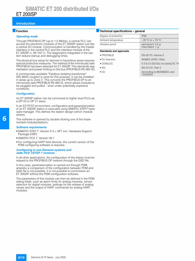
Technical specifications – general
Degree of protection IP30
Ambient temperature - 20 °C to + 70 °C
Vibration-proof permanent: 0.5 g, intermittent: 1 g
Standards and approvals
• PROFIBUS EN 50170, Volume 2
• EU directive 94/9/EC (ATEX 100a)
• CENELEC II 2 G (1) GD EEx d e [ib/ia] IIC T4
• IEC IEC 61131, Part 2
• CE According to 89/336/EEC and 73/23/EEC

Siemens IK PI News · July 2005 6/11
SIMATIC ET 200 distributed I/OsET 200iSP
IM 152-1 interface module
6
Overview
• The IM 152 interface module is plugged onto the correspond-ing terminal module TM-IM/EM (to be ordered separately). For redundant operation, two IM 152 are used. They are plugged onto the TM-IM/IM.
• The interface module IM 152 has the following properties: - Connects the ET 200iSP to PROFIBUS DP- Prepares data for the fitted electronic modules- The PROFIBUS address of ET 200iSP can be adjusted by
switch- Slot for MMC- Firmware updating over PROFIBUS DP or MMC
• Shutting down the 24 V DC supply voltage at the terminal module TM-PS also shuts down the interface module IM 152.
• The maximum address size is 244 byte inputs and 244 byte outputs.
Technical specifications
IM152-1 interface module 6ES7 152-1AA00-0AB0
Current consumption • from supply voltage 1L+, max. 30 mA• Power dissipation, typical 0.5 W
Interfaces • Physical interface, RS485 Yes; intrinsically safe
Protocols • PROFIBUS DP protocol Yes
PROFIBUS DP • Transmission rate, max. 1.5 Mbit/s; 9.6; 19.2; 45.45; 93.75;
187.5; 500 kBaud• SYNC capability Yes• FREEZE capability Yes• Direct data exchange
(lateral communication)Yes; slave to slave as publisher
Clock synchronism • Clock synchronous operation No
Status information/ interrupts/ diagnostics Interrupts
- Interrupts Yes- Acyclic function, interrupts Yes- Acyclic function, parameters Yes
Diagnostics- Diagnostic functions Yes
Diagnostic display LED- Bus fault BF (red) Yes- Group fault SF (red) Yes- Monitoring 24 V power supply
ON (green)Yes
IM152-1 interface module 6ES7 152-1AA00-0AB0
Time stamp • Description per digital input per digital output
entire module ET 200iSP• Accuracy 20 ms• Number of stamped digital inputs,
max.64; with precision class 20 ms
• Time of day format RFC 1119 Internet (ISP)• Time resolution 1 ms• Time interval for transm. the mes-
sage buffer if there is a mess.1,000 ms
• Time stamp with signal change in the case of a rising/falling edge as incoming outgoing event
Potentials/ electrical isolation • between supply load and
electronic componentsYes
Standards, approvals, certification • CE mark Yes• Type of protection to EN 50020
(CENELEC)II2 G EEx ib IIC T4
• Type of protection to KEMA 04 ATEX 1243
Dimensions and weight • Weight, approx. 245 g• Width 30 mm• Height 129 mm• Depth 136.5 mm
General information• Manufacturer’s ID (VendorID) 8110H
Terminal modules 6ES7 193-7AA00-0AA0 6ES7 193-7AA10-0AA0 6ES7 193-7AB00-0AA0
Standards, approvals, certification • CE mark No No No• Type of protection to comply
with EN 50020 (CENELEC)No No No
• Test number KEMA 04 ATEX 2242 04 ATEX 2242 04 ATEX 2242
Dimensions and weight • Weight, approx. 235 g 235 g 195 g• Width 60 mm 60 mm 60 mm• Height 190 mm 190 mm 190 mm• Depth 52 mm 52 mm 52 mm
Siemens IK PI News · July 20056/12
SIMATIC ET 200 distributed I/Os
IM 152-1 interface module
ET 200iSP
6
Ordering data Order No. Order No.
1) The ET 200iSP components must be ordered separatelyA) Subject to export regulations: AL: N and ECCN: EAR99H
IM152 including the terminat-ing module
• ET 200iSP-IM152-1 6ES7 152-1AA00-0AB0
Terminal modules for IM152
• TM-IM/EM60S A 6ES7 193-7AA00-0AA0
• TM-IM/EM60C A 6ES7 193-7AA10-0AA0
• TM-IM/IM 6ES7 193-7AB00-0AA0
Accessories
ET 200iSP product manual
• German 6ES7 152-1AA00-8AA0
• English 6ES7 152-1AA00-8BA0
Plug connector A 6ES7 972-0DA60-0XA0PROFIBUS connector with active terminating resistorFor RS 485-IS circuit; 1.5 Mbit/s
RS 485-IS segment 6ES7 972-0AC80-0XA0Isolating transition for coupling PROFIBUS DP to PROFIBUS RS 485-IS
Sheet of labelsDIN A4, perforated, consisting of 10 sheets each with 30 labels for electronic modules and 20 labels for IM 152
• Petrol 6ES7 193-7BH00-0AA0
• Red 6ES7 193-7BD00-0AA0
• Yellow 6ES7 193-7BB00-0AA0
• Light beige 6ES7 193-7BA00-0AA0
Identification labels, inscribedOrder quantity 1 set of 200 of each color for slot numbering
• 10 x Slot 1 to 2 8WA8 861-0AB
• 5 x Slot 1 to 40 8WA8 861-0AC
• 1 x Slot 1 to 64 2 x Slot 1 to 68
8WA8 861-0DA
Identification labels, blank 8WA8 848-2AYOrder quantity 1 set of 200 of each color for slot numbering
Standard rails S7-300
Standard rail 585 mm 6ES7 390-1AF85-0AA0
Standard rail 885 mm 6ES7 390-1AJ85-0AA0
Stainless steel housing IP66 for hazardous Zone 1 with safety class EEx eEmpty housing with no modules installed, for use in gaseous atmospheres, IP65 (IP54 if a breather gland is used) Wall housing 650 x 450 x 230 for the installation of up to 15 ET 200iSP modules• with 3 rows of cable glands
M16 (41 items) and 2 rows of cover plugs
6DL2 804-0AD30
• with 5 rows of cable glands M16 (66 items)
6DL2 804-0AD50
Accessories (continued)
Wall housing 950 x 450 x 230 for the installation of up to 25 ET 200iSP modules• with 3 rows of cable glands
M16 (68 items) and 2 rows of cover plugs
6DL2 804-0AE30
• with 5 rows of cable glands M16 (111 items)
6DL2 804-0AE50
Empty housing with no modules installed, for use in dusty atmo-spheres, IP65
Wall housing 650 x 450 x 230 for the installation of up to 15 ET 200iSP modules• with 3 rows of cable glands
M16 (41 items) and 2 rows of cover plugs
6DL2 804-0DD30
• with 5 rows of cable glands M16 (66 items)
6DL2 804-0DD50
Wall housing 950 x 450 x 230 for the installation of up to 25 ET 200iSP modules• with 3 rows of cable glands
M16 (68 items) and 2 rows of cover plugs
6DL2 804-0DE30
• with 5 rows of cable glands M16 (111 items)
6DL2 804-0DE50
Housing with ET 200iSP modules installed, for use in gaseous atmospheres, IP65 (IP54 when using a breather gland) 1)
Wall housing 650 x 450 x 230 for the installation of up to 15 ET 200iSP modules• with 3 rows of cable glands M16
(41 items) and 2 rows of cover plugs
6DL2 804-1AD30
• with 5 rows of cable glands M16 (66 items)
6DL2 804-1AD50
Wall housing 950 x 450 x 230 for the installation of up to 25 ET 200iSP modules• with 3 rows of cable glands
M16 (68 items) and 2 rows of cover plugs
6DL2 804-1AE30
• with 5 rows of cable glands M16 (111 items)
6DL2 804-1AE50
Housing with modules installed, for use in dusty atmospheres, IP65 1)
Wall housing 650 x 450 x 230 for the installation of up to 15 ET 200iSP modules• with 3 rows of cable glands
M16 (41 items) and 2 rows of cover plugs
6DL2 804-1DD30
• with 5 rows of cable glands M16 (66 items)
6DL2 804-1DD50
Wall housing 950 x 450 x 230 for the installation of up to 25 ET 200iSP modules• with 3 rows of cable glands
M16 (68 items) and 2 rows of cover plugs
6DL2 804-1DE30
• with 5 rows of cable glands M16 (111 items)
6DL2 804-1DE50
Siemens IK PI News · July 2005 6/13
SIMATIC ET 200 distributed I/OsET 200iSP
ET 200iSP digital electronics modulesand terminal modules
6
Overview
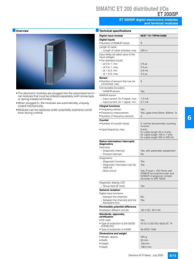
• The electronic modules are plugged into the associated termi-nal modules that must be ordered separately (with screw-type or spring-loaded terminals).
• When plugged in, the modules are automatically uniquely coded mechanically.
• Modules can be replaced under potentially explosive condi-tions during runtime.
Technical specifications
Digital input module 6ES7 131-7RF00-0AB0
Digital inputs • Number of NAMUR inputs 8
Length of cable- Length of cable shielded, max 200 m
Input delay (at rated value of the input voltage)• For standard inputs
- at 0 to 1, min. 2.8 µs- at 0 to 1, max. 3.5 µs- at 1 to 0, min 2.8 ms- at 1 to 0, max. 3.5 µs
Sensor • Number of sensors that can be
connected, max.8
Connectable encoders- NAMUR sensor Yes
NAMUR sensor- Input current, for 0 signal, max. 1.2 mA- Input current, for 1 signal, min. 2.1 mA
Integral functions • Frequency sensor Yes• Frequency measurement Yes; (gate time) 50ms; 200ms; 1s • Number of frequency sensors 2
Counter • Number of counter inputs 2; normal and periodic counting
function• Input frequency, max. 5 kHz;
for cable length 20 m 5 kHz; for cable length 100 m 1 kHz; for cable length 200 m 500 Hz
Status information/ interrupts/ diagnostics Interrupts
- Diagnostic interrupt Yes; with parameter assignment- Process interrupt No
Diagnostics- Diagnostic functions Yes- Diagnostic information can be
read outYes
- Short circuit Yes; R load < 150 Ohms with NAMUR encoder/encoder and NAMUR changeover contact /encoder to DIN 19234
Diagnostic display LED- Group fault SF (red) Yes
Galvanic isolation Digital input functions
- between the channels No- between the channels and the
backplane busYes
Permissible potential difference • between different circuits 60 V DC, 30 V AC
Standards, approvals, certification • CE mark Yes• Type of protection to EN 50020
(CENELEC)II2 G (1) GD EEx ib[ia] IIC T4
• Type of protection to KEMA 04 ATEX 1248
Dimensions and weight • Weight, approx. 255 g• Width 30 mm• Height 129 mm• Depth 136.5 mm

Siemens IK PI News · July 20056/14
SIMATIC ET 200 distributed I/Os
ET 200iSP digital electronics modulesand terminal modules
ET 200iSP
6
Technical specifications (continued)
Digital output module 6ES7 132-7RD00-0AB0 6ES7 132-7RD10-0AB0 6ES7 132-7RD20-0AB0
Current consumption • from load voltage L+ (no load), max. 340 mA max. 300 mA max. 400 mA• Power dissipation, typical 2.5 W 2.1 W 2.8 W
Digital outputs • Number of digital outputs 4 4 4• Length of cable shielded, max. 200 m 200 m 200 m• Length of cable unshielded, max. 200 m 200 m 200 m• Short-circuit protect. of the output Yes Yes Yes• Open-circuit voltage Uao (DC) 23.1 V 17.4 V 17.4 V• Internal resistance Ri 275 Ω 150 Ω 150 Ω
Trend points E- Voltage Ue (DC) 17.1 V 13.2 V 11 V- Current Ie 20 mA 27 mA; 54 mA with outputs
switched in parallel 40 mA; 80 mA with outputs switched in parallel
Output delay at resistive load- "0" after "1", max. 2 ms 2 ms 2 ms- "1" after "0", max. 1.5 ms 1.5 ms 1.5 ms
Parallel switching of 2 outputs- to increase power Yes Yes Yes
Switching frequency- at resistive load, max. 100 Hz 100 Hz 100 Hz- at inductive load, max. 2 Hz 2 Hz 2 Hz
Status inform./ interrupts/ diagn.Interrupts
- Interrupts No No No- Diagnostic interrupt Yes; with parameter assignment Yes; with parameter assignment Yes; with parameter assignment
Diagnostics- Diagn. inform. can be read out Yes Yes Yes- Wire break Yes; R1> 10 kOhms I<100 uA Yes; R1> 10 kOhms I<100 uA Yes; R1> 10 kOhms I<100 uA- Short circuit Yes; R< 800 Ohms (one output),
R< 40 Ohms (outputs switched par-allel)
Yes; R< 800 Ohms (one output), R< 40 Ohms (outputs switched par-allel)
Yes; R< 800 Ohms (one output), R< 40 Ohms (outputs switched par-allel)
Diagnostic display LED- Group fault SF (red) Yes Yes Yes- Status display digital out. (green) Yes; per channel Yes; per channel Yes; per channel
Galvanic isolation Digital output functions
- between the channels No No No- between the channels and the
backplane busYes Yes Yes
- between the channels and the load voltage L+
Yes Yes Yes
Permissible potential difference • between different circuits 60 V DC, 30 V AC 60 V DC, 30 V AC 60 V DC, 30 V AC
Standards, approvals, certific. • CE mark Yes Yes Yes• Type of protection to EN 50020
(CENELEC)II2 G (1) GD EEx ib[ia] IIC T4 II2 G (1) GD EEx ib[ia] IIC T4 II2 G (1) GD EEx ib[ia] IIC T4
• Type of protection to KEMA 04 ATEX 1249 04 ATEX 1249 04 ATEX 1249
Dimensions and weight • Weight, approx. 255 g 255 g 255 g• Width / Height / Depth in mm 30 / 129 / 136.5 30 / 129 / 136.5 30 / 129 / 136.5
Terminal modules 6ES7 193-7CA00-0AA0 6ES7 193-7CA10-0AA0
Standards, approvals, certific.• CE mark No No• Type of protection to comply with
EN 50020 (CENELEC)No No
• Type of protection to KEMA 04 ATEX 2242 04 ATEX 2242
Dimensions and weight • Weight, approx. 275 g 275 g• Width / Height / Depth in mm 60 / 190 / 52 60 / 190 / 52

Siemens IK PI News · July 2005 6/15
SIMATIC ET 200 distributed I/OsET 200iSP
ET 200iSP digital electronics modulesand terminal modules
6
Ordering data Order No. Order No.
1) The ET 200iSP components must be ordered separatelyA) Subject to export regulations: AL: N and ECCN: EAR99H
Digital input module 8 DI NAMUR
A 6ES7 131-7RF00-0AB0
8 x DI Namur
Digital output module 4 DO 23.1 V DC/20 mA
A 6ES7 132-7RD00-0AB0
Digital output module 4 DO 17.4 V DC/27 mA
A 6ES7 132-7RD10-0AB0
Digital output module 4 DO 17.4 V DC/40 mA
6ES7 132-7RD20-0AB0
4 x DO
TM-EM/EM60S A 6ES7 193-7CA00-0AA0Terminal module E60S (screw-type terminals)
TM-EM/EM60C A 6ES7 193-7CA10-0AA0Terminal module E60C (spring-loaded terminals)
Accessories
ET 200iSP product manual
• German 6ES7 152-1AA00-8AA0
• English 6ES7 152-1AA00-8BA0
Plug connector A 6ES7 972-0DA60-0XA0PROFIBUS connector with active terminating resistorFor RS 485-IS circuit; 1.5 Mbit/s
RS 485-IS segment 6ES7 972-0AC80-0XA0Isolating transition for coupling PROFIBUS DP to PROFIBUS RS 485-IS
Sheet of labelsDIN A4, perforated, consisting of 10 sheets each with 30 labels for electronic modules and 20 labels for IM 152
• Petrol 6ES7 193-7BH00-0AA0
• Red 6ES7 193-7BD00-0AA0
• Yellow 6ES7 193-7BB00-0AA0
• Light beige 6ES7 193-7BA00-0AA0
Identification labels, inscribedOrder quantity 1 set of 200 of each color for slot numbering
• 10 x Slot 1 to 2 8WA8 861-0AB
• 5 x Slot 1 to 40 8WA8 861-0AC
Identification labels, blank 8WA8 848-2AYOrder quantity 1 set of 200 of each color for slot numbering
Standard rails S7-300
Standard rail 585 mm 6ES7 390-1AF85-0AA0
Standard rail 885 mm 6ES7 390-1AJ85-0AA0
Stainless steel housing IP66 for hazardous Zone 1 with safety class EEx eEmpty housing with no modules installed, for use in gaseous atmospheres, IP65 (IP54 if a breather gland is used) Wall housing 650 x 450 x 230 for the installation of up to 15 ET 200iSP modules• with 3 rows of cable glands
M16 (41 items) and 2 rows of cover plugs
6DL2 804-0AD30
• with 5 rows of cable glands M16 (66 items)
6DL2 804-0AD50
Accessories (continued)
Wall housing 950 x 450 x 230 for the installation of up to 25 ET 200iSP modules• with 3 rows of cable glands
M16 (68 items) and 2 rows of cover plugs
6DL2 804-0AE30
• with 5 rows of cable glands M16 (111 items)
6DL2 804-0AE50
Empty housing with no modules installed, for use in dusty atmo-spheres, IP65
Wall housing 650 x 450 x 230 for the installation of up to 15 ET 200iSP modules• with 3 rows of cable glands
M16 (41 items) and 2 rows of cover plugs
6DL2 804-0DD30
• with 5 rows of cable glands M16 (66 items)
6DL2 804-0DD50
Wall housing 950 x 450 x 230 for the installation of up to 25 ET 200iSP modules• with 3 rows of cable glands
M16 (68 items) and 2 rows of cover plugs
6DL2 804-0DE30
• with 5 rows of cable glands M16 (111 items)
6DL2 804-0DE50
Housing with ET 200iSP modules installed, for use in gaseous atmospheres, IP65 (IP54 when using a breather gland) 1)
Wall housing 650 x 450 x 230 for the installation of up to 15 ET 200iSP modules• with 3 rows of cable glands M16
(41 items) and 2 rows of cover plugs
6DL2 804-1AD30
• with 5 rows of cable glands M16 (66 items)
6DL2 804-1AD50
Wall housing 950 x 450 x 230 for the installation of up to 25 ET 200iSP modules• with 3 rows of cable glands
M16 (68 items) and 2 rows of cover plugs
6DL2 804-1AE30
• with 5 rows of cable glands M16 (111 items)
6DL2 804-1AE50
Housing with modules installed, for use in dusty atmospheres, IP65 1)
Wall housing 650 x 450 x 230 for the installation of up to 15 ET 200iSP modules• with 3 rows of cable glands
M16 (41 items) and 2 rows of cover plugs
6DL2 804-1DD30
• with 5 rows of cable glands M16 (66 items)
6DL2 804-1DD50
Wall housing 950 x 450 x 230 for the installation of up to 25 ET 200iSP modules• with 3 rows of cable glands
M16 (68 items) and 2 rows of cover plugs
6DL2 804-1DE30
• with 5 rows of cable glands M16 (111 items)
6DL2 804-1DE50

Siemens IK PI News · July 20056/16
SIMATIC ET 200 distributed I/Os
ET 200iSP analog electronics modulesand terminal modules
ET 200iSP
6
Overview• The electronic modules are plugged into the associated termi-
nal modules that must be ordered separately (with screw-type or spring-loaded terminals).
• When plugged in, the modules are automatically uniquely coded mechanically.
• Modules can be replaced under potentially explosive condi-tions during runtime.
Siemens IK PI News · July 2005 6/17
SIMATIC ET 200 distributed I/OsET 200iSP
ET 200iSP analog electronics modulesand terminal modules
6
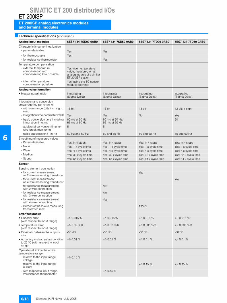
Technical specifications
Analog input modules 6ES7 134-7SD00-0AB0 6ES7 134-7SD50-0AB0 6ES7 134-7TD00-0AB0 6ES7 134-7TD50-0AB0
Voltages and currents Power supply of measuring transducers
- Short-circuit proof Yes- Supply current, max. 23 mA; per channel
Current consumption • from supply voltage L+, max. 30 mA 22 mA 320 mA 30 mA• Power dissipation, typical 0.4 W 0.4 W 2.7 W 0.4 W
Analog inputs • Number of analog inputs 4 4 4 4• Length of cable shielded, max 50 m 200 m 200 m 200 m• Perm. input volt. for the current
input (destr. lim.), max.90 mA 50 mA
• Technical unit for temperature measurement, adjustable
Yes Yes Yes Yes
Input ranges (rated values), voltages
- Voltage Yes- -80 mV to +80 mV Yes- Input resistance
(-80 mV to +80 mV)1,000 kΩ
Input ranges (rated values), currents
- Current Yes Yes- 4 to 20 mA Yes Yes; min. 295 Ohms
Input ranges (rated values), thermocouples
- Thermocouple Yes- Type B Yes- Input resistance (type B) 1,000 kΩ- Type C Yes- Input resistance (type C) 1,000 kΩ- Type E Yes- Input resistance (type E) 1,000 kΩ- Type J Yes- Input resistance (type J) 1,000 kΩ- Type K Yes- Input resistance (type K) 1,000 kΩ- Type L Yes- Input resistance (type L) 1,000 kΩ- Type N Yes- Input resistance (type N) 1,000 kΩ- Type R Yes- Input resistance (type R) 1,000 kΩ- Type S Yes- Input resistance (type S) 1,000 kΩ- Type T Yes- Input resistance (type T) 1,000 kΩ- Type U Yes- Input resistance (type U) 1,000 kΩ
Input ranges (rated values), resistances
- Resistance Yes- Input resistance (0 to 600 ohms) 0.6 kΩ
Input ranges (rated values), resistance thermometer
- Resistance thermometer Yes- Ni 100 Yes- Input resistance (Ni 100) 2,000 kΩ- Pt 100 Yes- Input resistance (Pt 100) 2,000 kΩ
Siemens IK PI News · July 20056/18
SIMATIC ET 200 distributed I/Os
ET 200iSP analog electronics modulesand terminal modules
ET 200iSP
6
Technical specifications (continued)
Analog input modules 6ES7 134-7SD00-0AB0 6ES7 134-7SD50-0AB0 6ES7 134-7TD00-0AB0 6ES7 134-7TD50-0AB0
Characteristic curve linearization- parameterizable Yes Yes- for thermocouple Yes- for resistance thermometer Yes
Temperature compensation- external temperature
compensation with compensating box possible
Yes; over temperature value, measured on an analog module of a similar ET 200iSP station
- internal temperature compensation possible
Yes; using the TC sensor module delivered
Analog value formation • Measuring principle integrating
(Sigma-Delta)integrating (Sigma-Delta)
integrating (Sigma-Delta)
integrating (Sigma-Delta)
Integration and conversion time/triggering per channel
- with over-range (bits incl. sign), max
16 bit 16 bit 13 bit 12 bit; + sign
- Integration time parameterizable Yes Yes No Yes- basic conversion time including
integration time, ms80 ms at 50 Hz; 66 ms at 60 Hz
80 ms at 50 Hz; 66 ms at 60 Hz
30
- additional conversion time for wire-break monitoring
5 5
- noise suppression f1 in Hz 50 Hz and 60 Hz 50 and 60 Hz 50 and 60 Hz 50 and 60 Hz
Smoothing of measured values- Parameterizable Yes; in 4 steps Yes; in 4 steps Yes; in 4 steps Yes; in 4 steps- None Yes; 1 x cycle time Yes; 1 x cycle time Yes; 1 x cycle time Yes; 1 x cycle time- Weak Yes; 4 x cycle time Yes; 4 x cycle time Yes; 4 x cycle time Yes; 4 x cycle time- Medium Yes; 32 x cycle time Yes; 32 x cycle time Yes; 32 x cycle time Yes; 32 x cycle time- Strong Yes; 64 x cycle time Yes; 64 x cycle time Yes; 64 x cycle time Yes; 64 x cycle time
Sensor
Sensing element connection- for current measurement,
as 2-wire measuring transducerYes
- for current measurement, as 4-wire measuring transducer
Yes
- for resistance measurement, with 2-wire connection
Yes
- for resistance measurement, with 3-wire connection
Yes
- for resistance measurement, with 4-wire connection
Yes
- Burden of the 2-wire measuring transformer, max.
750 Ω
Error/accuracies • Linearity error
(with respect to input range)+/- 0.015 % +/- 0.015 % +/- 0.015 % +/- 0.015 %
• Temperature error (with respect to input range)
+/- 0.02 %/K +/- 0.02 %/K +/- 0.005 %/K +/- 0.005 %/K
• Crosstalk between the outputs, min
-50 dB -50 dB -50 dB -50 dB
• Accuracy in steady-state condition to 25 °C (with respect to input range)
+/- 0.01 % +/- 0.01 % +/- 0.01 % +/- 0.01 %
Operational limit in the entire temperature range
- relative to the input range, voltage
+/- 0.15 %
- relative to the input range, current
+/- 0.15 % +/- 0.15 %
- with respect to input range, Wiresistance thermometer
+/- 0.15 %

Siemens IK PI News · July 2005 6/19
SIMATIC ET 200 distributed I/OsET 200iSP
ET 200iSP analog electronics modulesand terminal modules
6
Technical specifications (continued)
Analog input modules 6ES7 134-7SD00-0AB0 6ES7 134-7SD50-0AB0 6ES7 134-7TD00-0AB0 6ES7 134-7TD50-0AB0
Basic error limit (operational limit at 25 °C)
- relative to the input range, voltage
+/- 0.1 %
- relative to the input range, current
+/- 0.1 % +/- 0.1 %
- with respect to input range, resistance thermometer
+/- 0.1 %
Interference voltage suppression for f = n x (fl +/- 1 %)
- Series-mode interference (peak value of interference < rated val
70 dB 70 dB 70 dB 70 dB
- Common-mode interference, min
90 dB 90 dB
Status information/ interrupts/ diagnostics
Interrupts- Diagnostic interrupt Yes; can be assigned
parametersYes; can be assigned parameters
Yes; can be assigned parameters
Yes; can be assigned parameters
- Limit value interrupt Yes; can be assigned parameters
Yes; can be assigned parameters
Yes; can be assigned parameters
Yes; can be assigned parameters
Diagnostics- Diagnostic information can be
read outYes Yes Yes Yes
- Wire break Yes Yes Yes- Short circuit Yes
Diagnostic display LED- Group fault SF (red) Yes Yes Yes Yes
Galvanic isolation
Analog inputs- between the channels Yes; functional Yes No No- between the channels and the
backplane busYes Yes Yes Yes
Standards, approvals, certification
• CE mark Yes Yes Yes Yes
• Type of protection to EN 50020 (CENELEC)
II2 G (1) GD EEx ib[ia] IIC T4
II2 G (1) GD Eex ib[ia] IIC T4
II2 G (1) GD EEx ib[ia] IIC T4
II2 G (1) GD EEx ib[ia] IIC T4
• Type of protection to KEMA 04 ATEX 1246 04 ATEX 1247 04 ATEX 1244 04 ATEX 1245
Dimensions and weight
• Weight, approx. 230 g 230 g 230 g 230 g
• Width 30 mm 30 mm 30 mm 30 mm
• Height 129 mm 129 mm 129 mm 129 mm
• Depth 136.5 mm 136.5 mm 136.5 mm 136.5 mm

Siemens IK PI News · July 20056/20
SIMATIC ET 200 distributed I/Os
ET 200iSP analog electronics modulesand terminal modules
ET 200iSP
6
Technical specifications (continued)
Analog output modules 6ES7 135-7TD00-0AB0
Current consumption • from load voltage 1L+, max 330 mA• Power dissipation, max. 2.7 W
Analog outputs • Number of analog outputs 4• Length of cable shielded, max 200 m
Output ranges, current- 4 to 20 mA Yes
Actuator connection- for current output 2-wire
connectionYes
Burden resistance (in the nominal output range)
- at current outputs, max. 750 Ω
Analog value formation Integration and conversion time/triggering per channel
- with over-range (bits incl. sign), max.
14 bit
Settling time- for resistive load 4 ms- for capacitive load 40 ms- for inductive load 40 ms
Error/accuracies • linearity error
(with respect to output range)+/- 0.015 %
• temperature error(with respect to output range)
+/- 0.005 %/K
• Crosstalk between the outputs, min
-50 dB
• Repetition acurracy in steady-state condition at 25 °C (with respect to output range)
+/- 0.01 %
Operational limit over entire temperature range• with respect to output range,
current+/- 0.15 %
Basic error limit (Operational limit at 25 °C) • with respect to output range,
current+/- 0.1 %
Analog output modules 6ES7 135-7TD00-0AB0
Status information/ interrupts/ diagnostics • Applying substitute values Yes
Interrupts- Diagnostic interrupt Yes
Diagnostics- Diagnostic information can be
read outYes
- Wire break Yes- Short circuit Yes
Diagnostic display LED- Group fault SF (red) Yes
Galvanic isolation Analog output functions
- between the channels No- between the channels and the
backplane busYes
Standards, approvals, certificates • Type of protection to KEMA 04 ATEX 1250
Dimensions and weight • Weight, approx. 265 g• Width 30 mm• Height 129 mm• Depth 136.5 mm
Terminal modules 6ES7 193-7CA00-0AA0
6ES7 193-7CA10-0AA0
Standards, approvals, certification • CE mark No No• Type of protection to comply
with EN 50020 (CENELEC)No No
• Test number KEMA 04 ATEX 2242 04 ATEX 2242
Dimensions and weight
• Weight, approx. 275 g 275 g
• Width 60 mm 60 mm
• Height 190 mm 190 mm
• Depth 52 mm 52 mm
Siemens IK PI News · July 2005 6/21
SIMATIC ET 200 distributed I/OsET 200iSP
ET 200iSP analog electronics modulesand terminal modules
6
Ordering data Order No. Order No.
1) The ET 200iSP components must be ordered separatelyA) Subject to export regulations: AL: N and ECCN: EAR99H
Analog input modules
4 AI I 2WIRE HART A 6ES7 134-7TD00-0AB0
4 AI I 4WIRE HART 6ES7 134-7TD50-0AB0
4 AI RTD 6ES7 134-7SD50-0AB0
4 AI TC 6ES7 134-7SD00-0AB0
Analog output modules
4 AO I HART A 6ES7 135-7TD00-0AB0
Terminal modules
TM-EM/EM60S A 6ES7 193-7CA00-0AA0Terminal module E60S (screw-type terminals)
TM-EM/EM60C A 6ES7 193-7CA10-0AA0Terminal module E60C (spring-loaded terminals)
Accessories
ET 200iSP product manual
• German 6ES7 152-1AA00-8AA0
• English 6ES7 152-1AA00-8BA0
Plug connectorPROFIBUS connector with active terminating resistor
A 6ES7 972-0DA60-0XA0
For RS 485-IS circuit; 1.5 Mbit/s
RS 485-IS segment 6ES7 972-0AC80-0XA0Isolating transition for coupling PROFIBUS DP to PROFIBUS RS 485-IS
Sheet of labelsDIN A4, perforated, consisting of 10 sheets each with 30 labels for electronic modules and 20 labels for IM 152
• Petrol 6ES7 193-7BH00-0AA0
• Red 6ES7 193-7BD00-0AA0
• Yellow 6ES7 193-7BB00-0AA0
• Light beige 6ES7 193-7BA00-0AA0
Identification labels, inscribedOrder quantity 1 set of 200 of each color for slot numbering
• 10 x Slot 1 to 2 8WA8 861-0AB
• 5 x Slot 1 to 40 8WA8 861-0AC
Identification labels, blank 8WA8 848-2AYOrder quantity 1 set of 200 of each color for slot numbering
Standard rails S7-300
Standard rail 585 mm 6ES7 390-1AF85-0AA0
Standard rail 885 mm 6ES7 390-1AJ85-0AA0
Stainless steel housing IP66 for hazardous Zone 1 with safety class EEx eEmpty housing with no modules installed, for use in gaseous atmospheres, IP65 (IP54 if a breather gland is used) Wall housing 650 x 450 x 230 for the installation of up to 15 ET 200iSP modules• with 3 rows of cable glands
M16 (41 items) and 2 rows of cover plugs
6DL2 804-0AD30
• with 5 rows of cable glands M16 (66 items)
6DL2 804-0AD50
Accessories (continued)
Wall housing 950 x 450 x 230 for the installation of up to 25 ET 200iSP modules• with 3 rows of cable glands
M16 (68 items) and 2 rows of cover plugs
6DL2 804-0AE30
• with 5 rows of cable glands M16 (111 items)
6DL2 804-0AE50
Empty housing with no modules installed, for use in dusty atmo-spheres, IP65
Wall housing 650 x 450 x 230 for the installation of up to 15 ET 200iSP modules• with 3 rows of cable glands
M16 (41 items) and 2 rows of cover plugs
6DL2 804-0DD30
• with 5 rows of cable glands M16 (66 items)
6DL2 804-0DD50
Wall housing 950 x 450 x 230 for the installation of up to 25 ET 200iSP modules• with 3 rows of cable glands
M16 (68 items) and 2 rows of cover plugs
6DL2 804-0DE30
• with 5 rows of cable glands M16 (111 items)
6DL2 804-0DE50
Housing with ET 200iSP modules installed, for use in gaseous atmospheres, IP65 (IP54 when using a breather gland) 1)
Wall housing 650 x 450 x 230 for the installation of up to 15 ET 200iSP modules• with 3 rows of cable glands M16
(41 items) and 2 rows of cover plugs
6DL2 804-1AD30
• with 5 rows of cable glands M16 (66 items)
6DL2 804-1AD50
Wall housing 950 x 450 x 230 for the installation of up to 25 ET 200iSP modules• with 3 rows of cable glands
M16 (68 items) and 2 rows of cover plugs
6DL2 804-1AE30
• with 5 rows of cable glands M16 (111 items)
6DL2 804-1AE50
Housing with modules installed, for use in dusty atmospheres, IP65 1)
Wall housing 650 x 450 x 230 for the installation of up to 15 ET 200iSP modules• with 3 rows of cable glands
M16 (41 items) and 2 rows of cover plugs
6DL2 804-1DD30
• with 5 rows of cable glands M16 (66 items)
6DL2 804-1DD50
Wall housing 950 x 450 x 230 for the installation of up to 25 ET 200iSP modules• with 3 rows of cable glands
M16 (68 items) and 2 rows of cover plugs
6DL2 804-1DE30
• with 5 rows of cable glands M16 (111 items)
6DL2 804-1DE50
Siemens IK PI News · July 20056/22
SIMATIC ET 200 distributed I/Os
ET 200iSP reserve modules and terminal modules
ET 200iSP
6
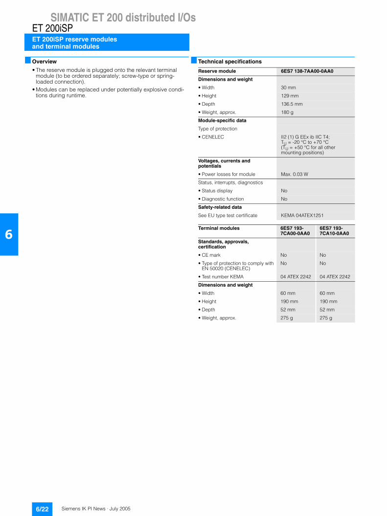
Overview
• The reserve module is plugged onto the relevant terminal module (to be ordered separately; screw-type or spring-loaded connection).
• Modules can be replaced under potentially explosive condi-tions during runtime.
Technical specifications
Reserve module 6ES7 138-7AA00-0AA0
Dimensions and weight
• Width 30 mm
• Height 129 mm
• Depth 136.5 mm
• Weight, approx. 180 g
Module-specific data
Type of protection
• CENELEC II2 (1) G EEx ib IIC T4; TU = -20 °C to +70 °C(TU = +50 °C for all other mounting positions)
Voltages, currents and potentials
• Power losses for module Max. 0.03 W
Status, interrupts, diagnostics
• Status display No
• Diagnostic function No
Safety-related data
See EU type test certificate KEMA 04ATEX1251
Terminal modules 6ES7 193-7CA00-0AA0
6ES7 193-7CA10-0AA0
Standards, approvals, certification
• CE mark No No
• Type of protection to comply with EN 50020 (CENELEC)
No No
• Test number KEMA 04 ATEX 2242 04 ATEX 2242
Dimensions and weight
• Width 60 mm 60 mm
• Height 190 mm 190 mm
• Depth 52 mm 52 mm
• Weight, approx. 275 g 275 g
Siemens IK PI News · July 2005 6/23
SIMATIC ET 200 distributed I/OsET 200iSP
ET 200iSP reserve modulesand terminal modules
6
Ordering data Order No. Order No.
1) The ET 200iSP components must be ordered separatelyA) Subject to export regulations: AL: N and ECCN: EAR99H
Reservemodul A 6ES7 138-7AA00-0AA0
Terminal modules
TM-EM/EM60S A 6ES7 193-7CA00-0AA0Terminal module E60S (screw-type terminals)
TM-EM/EM60C A 6ES7 193-7CA10-0AA0Terminal module E60C (spring-loaded terminals)
Accessories
ET 200iSP product manual
• German 6ES7 152-1AA00-8AA0
• English 6ES7 152-1AA00-8BA0
Plug connector A 6ES7 972-0DA60-0XA0PROFIBUS connector with active terminating resistorFor RS 485-IS circuit; 1.5 Mbit/s
RS 485-IS segment 6ES7 972-0AC80-0XA0Isolating transition for coupling PROFIBUS DP to PROFIBUS RS 485-IS
Sheet of labelsDIN A4, perforated, consisting of 10 sheets each with 30 labels for electronic modules and 20 labels for IM 152
• Petrol 6ES7 193-7BH00-0AA0
• Red 6ES7 193-7BD00-0AA0
• Yellow 6ES7 193-7BB00-0AA0
• Light beige 6ES7 193-7BA00-0AA0
Identification labels, inscribedOrder quantity 1 set of 200 of each color for slot numbering
• 10 x Slot 1 to 2 8WA8 861-0AB
• 5 x Slot 1 to 40 8WA8 861-0AC
Identification labels, blank 8WA8 848-2AYOrder quantity 1 set of 200 of each color for slot numbering
Standard rails S7-300
Standard rail 585 mm 6ES7 390-1AF85-0AA0
Standard rail 885 mm 6ES7 390-1AJ85-0AA0
Stainless steel housing IP66 for hazardous Zone 1 with safety class EEx eEmpty housing with no modules installed, for use in gaseous atmospheres, IP65 (IP54 if a breather gland is used) Wall housing 650 x 450 x 230 for the installation of up to 15 ET 200iSP modules• with 3 rows of cable glands
M16 (41 items) and 2 rows of cover plugs
6DL2 804-0AD30
• with 5 rows of cable glands M16 (66 items)
6DL2 804-0AD50
Accessories (continued)
Wall housing 950 x 450 x 230 for the installation of up to 25 ET 200iSP modules• with 3 rows of cable glands
M16 (68 items) and 2 rows of cover plugs
6DL2 804-0AE30
• with 5 rows of cable glands M16 (111 items)
6DL2 804-0AE50
Empty housing with no modules installed, for use in dusty atmo-spheres, IP65
Wall housing 650 x 450 x 230 for the installation of up to 15 ET 200iSP modules• with 3 rows of cable glands
M16 (41 items) and 2 rows of cover plugs
6DL2 804-0DD30
• with 5 rows of cable glands M16 (66 items)
6DL2 804-0DD50
Wall housing 950 x 450 x 230 for the installation of up to 25 ET 200iSP modules• with 3 rows of cable glands
M16 (68 items) and 2 rows of cover plugs
6DL2 804-0DE30
• with 5 rows of cable glands M16 (111 items)
6DL2 804-0DE50
Housing with ET 200iSP modules installed, for use in gaseous atmospheres, IP65 (IP54 when using a breather gland) 1)
Wall housing 650 x 450 x 230 for the installation of up to 15 ET 200iSP modules• with 3 rows of cable glands M16
(41 items) and 2 rows of cover plugs
6DL2 804-1AD30
• with 5 rows of cable glands M16 (66 items)
6DL2 804-1AD50
Wall housing 950 x 450 x 230 for the installation of up to 25 ET 200iSP modules• with 3 rows of cable glands
M16 (68 items) and 2 rows of cover plugs
6DL2 804-1AE30
• with 5 rows of cable glands M16 (111 items)
6DL2 804-1AE50
Housing with modules installed, for use in dusty atmospheres, IP65 1)
Wall housing 650 x 450 x 230 for the installation of up to 15 ET 200iSP modules• with 3 rows of cable glands
M16 (41 items) and 2 rows of cover plugs
6DL2 804-1DD30
• with 5 rows of cable glands M16 (66 items)
6DL2 804-1DD50
Wall housing 950 x 450 x 230 for the installation of up to 25 ET 200iSP modules• with 3 rows of cable glands
M16 (68 items) and 2 rows of cover plugs
6DL2 804-1DE30
• with 5 rows of cable glands M16 (111 items)
6DL2 804-1DE50

Siemens IK PI News · July 20056/24
SIMATIC ET 200 distributed I/Os
ET 200iSP power supply unit
ET 200iSP
6
Overview
The power supply (PS) is plugged into the associated terminal module TM-PS-A or TM-PS-B (with redundancy; to be ordered separately).
The power supply unit fulfills the following functions:• It provides reliable isolated power supply for the ET 200iSP with
the necessary operating voltages for: - Logic (through the backplane bus)- PROFIBUS DP interface of IM 152-1- Powerbus (for supplying the electronic modules)
• Takes over the safety limit of the output voltage• Has an explosion-proof metal enclosure (explosion protection
EEx d)• Can be redundantly configured
Technical specifications
Ordering data Order No.
Power Supply (PS) 6ES7 138-7EA00-0AA0
Voltages and currents • Line supply/voltage failure
buffering, min.0.25 ms; for power bus and back-plane bus; (15 ms for IM 152)
Load voltage L+- Rated value (DC) 24 V- Reverse polarity protection Yes
Current consumption • from supply voltage L+, max. 4 mA• Power dissipation, typical 20 W
Ex(i)-modules Maximum values of the input circuits (per channel)
- Um (fault voltage), max 60 V; dc
Status information/ interrupts/ diagnostics • Status display Yes
Interrupts No
Diagnostics• Diagnostic information can be
read outYes; over IM 152
Diagnostic display LED• Group fault SF (red) No
Isolation
tested• across all secondary voltages 500 V AC• across supply voltage and all
secondary voltages 1500 V AC
Galvanic isolation • between supply load and
electronic componentsYes
Standards, approvals, certific.• CE mark Yes• Type of protection according to
EN 50020 (CENELEC)II2 G EEx de [ib] IIC T4
• Type of protection to KEMA 04 ATEX 2263
Dimensions and weight • Weight, approx. 2,700 g• Width 60 mm• Height 190 mm• Depth 136.5 mm
Terminal modules 6ES7 193-7DA00-0AA0
6ES7 193-7DB00-0AA0
Standards, approvals, certific.• CE mark Yes Yes• Type of protection according to
EN 50020 (CENELEC)II2 G (1) GD EEx de[ia/ib] IIC T4
II2 G (1) GD EEx de[ia/ib] IIC T4
• Type of protection to KEMA 04 ATEX 2242 04 ATEX 2242
Dimensions and weight • Weight, approx. 235 g 235 g• Width 60 mm 60 mm• Height 190 mm 90 mm• Depth 52 mm 52 mm
Power supply module PS 6ES7 138-7EA00-0AA0
Terminal module TM-PS-A standard
6ES7 193-7DA00-0AA0
Terminal module TM-PS-B for redundant operation
6ES7 193-7DB00-0AA0
Siemens IK PI News · July 2005 6/25
SIMATIC ET 200 distributed I/OsET 200pro
Introduction
6
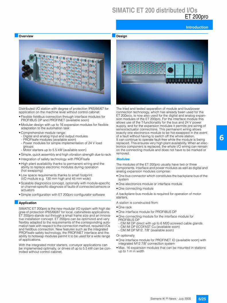
Overview
Distributed I/O station with degree of protection IP65/66/67 for application on the machine level without control cabinet• Flexible fieldbus connection through interface modules for
PROFIBUS DP and PROFINET (available soon)• Modular design with up to 16 expansion modules for flexible
adaptation to the automation task• Comprehensive module range:
- Digital and analog input and output modules- PROFIsafe modules (available soon)- Power modules for simple implementation of 24 V load
groups- Motor starters up to 5.5 kW (available soon)
• Simple, quick assembly and high vibration strength due to rack• Integration of safety technology with PROFIsafe• High plant availability thanks to permanent wiring and the
ability to replace electronic modules during operation (hot swapping)
• Low space requirements thanks to small footprint (I/O module e.g. 130 mm high and 45 mm wide)
• Scalable diagnostics concept, optionally with module-specific or channel-specific diagnosis of faults of connected sensors or actuators
• Simple configuration with ET 200pro configurator software
Application
SIMATIC ET 200pro is the new modular I/O system with high de-gree of protection IP65/66/67 for local, cabinetless applications. ET 200pro stands out through a small frame size and an innova-tive installation concept. ET 200pro can be optimized and very flexibly adapted to the requirements of the corresponding auto-mation task with respect to the connection method, required I/Os and fieldbus connection. New features such as the integrated PROFIsafe safety technology, the PROFINET interface and the ability to hotswap modules permit it to be used for a wide range of applications.
With the integrated motor starters, conveyor applications can be implemented optimally, or drives of up to 5.5 kW can be con-trolled without control cabinet.
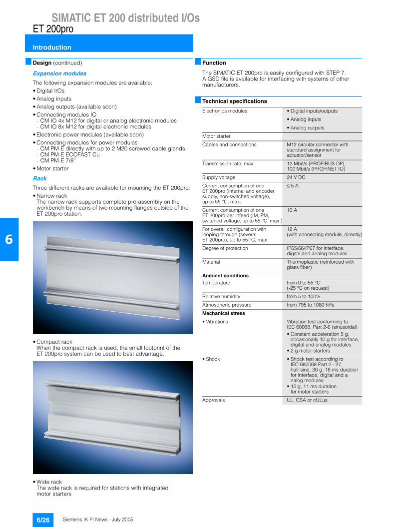
Design
The tried and tested separation of module and bus/power connection technology, which has already been used for the ET 200eco, is now also used for the digital and analog expan-sion modules of the ET 200pro. For the interface module this allows use of the T-functionality for the bus and 24 V power supply, and for the expansion modules it permits pre-wiring of sensor/actuator connections. This permanent wiring allows exactly one electronics module to be hot-swapped in the event of a fault without having to switch off the whole station. It can continue to operate fault-free while the module is being replaced. This ensures very high plant availability. When an elec-tronics component is replaced, the whole I/O wiring can remain on the connecting module and does not have to be marked or removed.
Modules
The modules of the ET 200pro usually have two or three components. Interface and power modules as well as digital and analog expansion modules comprise:• One bus connector which constitutes the backplane bus of the
system• One electronics module or interface module• One connecting module
A backplane bus module is required for operation of motor starters.
A station is constructed from:• One rack• One interface module for PROFIBUS DP• One connecting module for the interface module for
PROFIBUS DP - CM IM DP direct with up to 6 M20 screwed cable glands- CM IM DP ECOFAST Cu (available soon)- CM IM DP M12, 7/8" (available soon)
Or optionally• One interface module for PROFINET IO (available soon) with
integrated M12 7/8" connection system• Max. 16 expansion modules that can be mounted in stations
up to 1 m in width
Siemens IK PI News · July 20056/26
SIMATIC ET 200 distributed I/Os
Introduction
ET 200pro
6
Design (continued)
Expansion modules
The following expansion modules are available:• Digital I/Os• Analog inputs• Analog outputs (available soon)• Connecting modules IO
- CM IO 4x M12 for digital or analog electronic modules- CM IO 8x M12 for digital electronic modules
• Electronic power modules (available soon)• Connecting modules for power modules
- CM PM-E directly with up to 2 M20 screwed cable glands- CM PM-E ECOFAST Cu- CM PM-E 7/8”
• Motor starter
Rack
Three different racks are available for mounting the ET 200pro:• Narrow rack
The narrow rack supports complete pre-assembly on the workbench by means of two mounting flanges outside of the ET 200pro station.
• Compact rackWhen the compact rack is used, the small footprint of the ET 200pro system can be used to best advantage.
• Wide rackThe wide rack is required for stations with integrated motor starters
Function
The SIMATIC ET 200pro is easily configured with STEP 7. A GSD file is available for interfacing with systems of other manufacturers.
Technical specifications
Electronics modules • Digital inputs/outputs
• Analog inputs
• Analog outputs
Motor starter
Cables and connections M12 circular connector with standard assignment for actuator/sensor
Transmission rate, max. 12 Mbit/s (PROFIBUS DP), 100 Mbit/s (PROFINET IO)
Supply voltage 24 V DC
Current consumption of one ET 200pro (internal and encoder supply, non-switched voltage), up to 55 °C, max.
≤ 5 A
Current consumption of one ET 200pro per infeed (IM, PM, switched voltage, up to 55 °C, max.)
10 A
For overall configuration with looping through (several ET 200pro), up to 55 °C, max.
16 A (with connecting module, directly)
Degree of protection IP65/66/IP67 for interface, digital and analog modules
Material Thermoplastic (reinforced with glass fiber)
Ambient conditions Temperature from 0 to 55 °C
(-25 °C on request)
Relative humidity from 5 to 100%
Atmospheric pressure from 795 to 1080 hPa
Mechanical stress
• Vibrations Vibration test conforming to IEC 60068, Part 2-6 (sinusoidal)• Constant acceleration 5 g,
occasionally 10 g for interface, digital and analog modules
• 2 g motor starters
• Shock • Shock test according to IEC 680068 Part 2 - 27, half-sine, 30 g, 18 ms duration for interface, digital and analog modules
• 15 g, 11 ms duration for motor starters
Approvals UL, CSA or cULus
Siemens IK PI News · July 2005 6/27
SIMATIC ET 200 distributed I/OsET 200pro
IM 154-1 and IM 154-2 interface modules
6
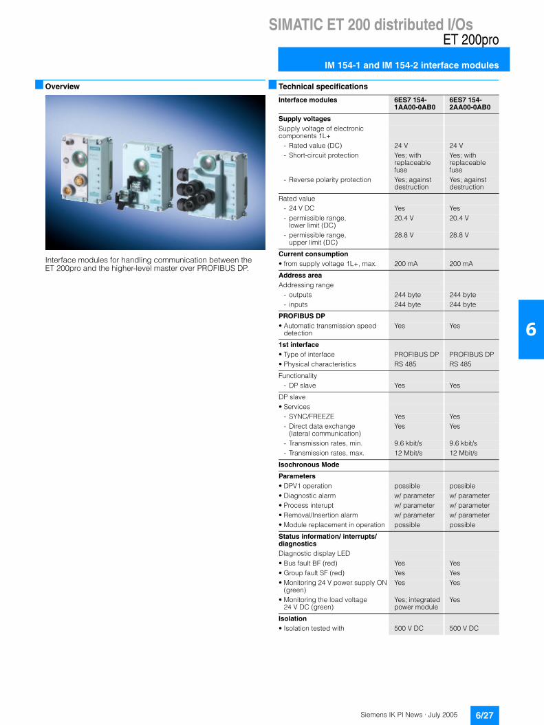
Overview
Interface modules for handling communication between the ET 200pro and the higher-level master over PROFIBUS DP.
Technical specifications
Interface modules 6ES7 154-1AA00-0AB0
6ES7 154-2AA00-0AB0
Supply voltages Supply voltage of electronic components 1L+
- Rated value (DC) 24 V 24 V- Short-circuit protection Yes; with
replaceable fuse
Yes; with replaceable fuse
- Reverse polarity protection Yes; against destruction
Yes; against destruction
Rated value- 24 V DC Yes Yes- permissible range,
lower limit (DC)20.4 V 20.4 V
- permissible range, upper limit (DC)
28.8 V 28.8 V
Current consumption • from supply voltage 1L+, max. 200 mA 200 mA
Address area Addressing range
- outputs 244 byte 244 byte- inputs 244 byte 244 byte
PROFIBUS DP • Automatic transmission speed
detectionYes Yes
1st interface • Type of interface PROFIBUS DP PROFIBUS DP• Physical characteristics RS 485 RS 485
Functionality- DP slave Yes Yes
DP slave• Services
- SYNC/FREEZE Yes Yes- Direct data exchange
(lateral communication)Yes Yes
- Transmission rates, min. 9.6 kbit/s 9.6 kbit/s- Transmission rates, max. 12 Mbit/s 12 Mbit/s
Isochronous Mode
Parameters• DPV1 operation possible possible• Diagnostic alarm w/ parameter w/ parameter• Process interupt w/ parameter w/ parameter• Removal/Insertion alarm w/ parameter w/ parameter• Module replacement in operation possible possible
Status information/ interrupts/ diagnostics Diagnostic display LED• Bus fault BF (red) Yes Yes• Group fault SF (red) Yes Yes• Monitoring 24 V power supply ON
(green)Yes Yes
• Monitoring the load voltage 24 V DC (green)
Yes; integrated power module
Yes
Isolation • Isolation tested with 500 V DC 500 V DC

Siemens IK PI News · July 20056/28
SIMATIC ET 200 distributed I/Os
IM 154-1 and IM 154-2 interface modules
ET 200pro
6
Technical specifications (continued)
Ordering data Order No.
A) Subject to export regulations: AL: N and ECCN: EAR99H
Ordering data Order No.
Interface modules 6ES7 154-1AA00-0AB0
6ES7 154-2AA00-0AB0
Galvanic isolation • between backplane bus and
electronic componentsNo No
• between supply load and electronic components
Yes Yes
Environmental requirements Operating temperature
- min. -25 °C -25 °C- max. 55 °C 55 °C
Storage/transportation temperature - min. -40 °C -40 °C- max. 70 °C 70 °C
Degree of protection and class of protection
- IP65 Yes Yes- IP66 Yes Yes- IP67 Yes Yes
Dimensions and weight • Weight, approx. 395 g 415 g• Width 90 mm 90 mm• Height 130 mm 130 mm• Depth 59.3 mm 59.3 mm
General information
IM154-1 interface module A 6ES7 154-1AA00-0AB0For ET 200pro; for communication between ET 200pro and higher-level masters over PROFIBUS DP
IM154-2 High Feature interface module
A 6ES7 154-2AA00-0AB0
For ET 200pro; for communication between ET 200pro and higher-level masters over PROFIBUS DP; support of PROFIsafe
Accessories
CM IM DP ECOFAST connecting module
A 6ES7 194-4AA00-0AA0
For connecting PROFIBUS DP and the 24 V power supply to PROFIBUS interface modules, 2 ECOFAST Cu connections
CM IM DP direct connecting module
A 6ES7 194-4AC00-0AA0
For connecting PROFIBUS DP and the 24 V power supply directly to the PROFIBUS inter-face modules, up to six M20 screwed cable glands
CM IM DP M12, 7/8" connecting module
A 6ES7 194-4AD00-0AA0
For connecting PROFIBUS DP and the 24 V power supply to PROFIBUS interface modules, 2 x M12 and 2 x 7/8"
Accessories for CM IM DP ECOFAST
PROFIBUS ECOFAST hybrid cable, pre-assembledWith 2 ECOFAST connectors, trailing-type cable 2 x CU 0.64 mm2 and 4 x Cu 1.5 mm2
• 1.5 m long 6XV1 830-7BH15
• 3.0 m long 6XV1 830-7BH30
• 5.0 m long 6XV1 830-7BH50
• 10 m long 6XV1 830-7BN10
• 15 m long 6XV1 830-7BN15
• 20 m long 6XV1 830-7BN20
• 25 m long 6XV1 830-7BN25
• 30 m long 6XV1 830-7BN30
• 35 m long 6XV1 830-7BN35
• 40 m long 6XV1 830-7BN40
• 45 m long 6XV1 830-7BN45
• 50 m long 6XV1 830-7BN50
PROFIBUS ECOFAST hybrid cable GP, pre-assembledWith 2 ECOFAST connectors, trailing-type cable 2 x CU 0.64 mm2 and 4 x Cu 1.5 mm2
• 1.5 m long 6XV1 860-3PH15
• 3.0 m long 6XV1 860-3PH30
• 5.0 m long 6XV1 860-3PH50
• 10 m long 6XV1 860-3PN10
• 15 m long 6XV1 860-3PN15
• 20 m long 6XV1 860-3PN20
• 25 m long 6XV1 860-3PN25
• 30 m long 6XV1 860-3PN30
• 35 m long 6XV1 860-3PN35
• 40 m long 6XV1 860-3PN40
• 45 m long 6XV1 860-3PN45
• 50 m long 6XV1 860-3PN50
PROFIBUS ECOFAST hybrid cable, non-assembledTrailing-type cable 2 x CU 0.64 mm2 and 4 x Cu 1.5 mm2
• 50 m long 6XV1 830-7AN50
• 100 m long 6XV1 830-7AT10
PROFIBUS ECOFAST hybrid cable GP, non-assembledTrailing-type cable 2 x CU 0.64 mm2 and 4 x Cu 1.5 mm2
• 50 m long 6XV1 860-4PN50
• 100 m long 6XV1 860-4PT10
PROFIBUS ECOFAST hybrid connector 180ECOFAST Cu, 2 x Cu, 4 x 1.5 mm2,, HANBRID connector• with male insert, 5 per pack 6GK1 905-0CA00
• with female insert, 5 per pack 6GK1 905-0CB00

Siemens IK PI News · July 2005 6/29
SIMATIC ET 200 distributed I/OsET 200pro
IM 154-1 and IM 154-2 interface modules
6
Ordering data Order No. Order No.
A) Subject to export regulations: AL: N and ECCN: EAR99HD) Subject to export regulations: AL: N and ECCN: 5D992B1
Accessories for CM IM DP ECOFAST (continued)
PROFIBUS ECOFAST hybrid connector angularECOFAST Cu, 2 x Cu, 4 x 1.5 mm2,, HANBRID connector• with male insert, 5 per pack 6GK1 905-0CC00
• with female insert, 5 per pack 6GK1 905-0CD00
ECOFAST covering cap 6ES7 194-1JB10-0XA0For protecting unused bus connections for ET 200pro; 10 items per pack
Accessories for CM IM DP direct
PROFIBUS trailing cable 6XV1 830-3EH10Max. acceleration 4 m/s2, at least 3,000,000 bending cycles, bend-ing radius 60 mm, 2-core shielded, sold by the meter, minimum order quantity 20 m, maximum order quantity 1,000 m
PROFIBUS FC Food bus cable 6XV1 830-0GH10With PE sheath for use in the food and beverages industry, 2-core, shielded, sold by the meter, minimum order quantity 20 m, maximum order quantity 1,000 m
PROFIBUS FC Robust bus cable
6XV1 830-0JH10
With PUR sheath for use under conditions of extreme mechani-cal stress and aggressive chemicals, 2-core, shielded, sold by the meter, minimum order quantity 20 m, maximum order quantity 1,000 m
Power cable 6XV1 830-8AH105-core, 5 x 1.5 mm2, trailing type, sold by the meter, minimum order quantity 20 m, maximum order quantity 1,000 m
Accessories for CM IM DP M12, 7/8"
PROFIBUS M12 connecting cablePre-assembled with two M12 connectors, 5-pin
• 1.5 m long 6XV1 830-3DH15
• 2.0 m long 6XV1 830-3DH20
• 3.0 m long 6XV1 830-3DH30
• 5.0 m long 6XV1 830-5DH50
• 10 m long 6XV1 830-3DN10
• 15 m long 6XV1 830-3DN15
7/8" connecting cable to power supply5-core, 5 x 1.5 mm2, trailing type, pre-assembled with two 7/8" connectors, 5-pin
• 1.5 m long 6XV1 822-5BH15
• 2.0 m long 6XV1 822-5BH20
• 3.0 m long 6XV1 822-5BH30
• 5.0 m long 6XV1 822-5BH50
• 10 m long 6XV1 822-5BN10
• 15 m long 6XV1 822-5BN15
Accessories for CM IM DP M12, 7/8" (continued)
M12 cable connectorFor ET 200eco, with axial cable outlet
• with male insert, 5 per pack 6GK1 905-0EA00
• with female insert, 5 per pack 6GK1 905-0EB00
7/8" cable connectorFor ET 200eco, with axial cable outlet
• with male insert, 5 per pack 6GK1 905-0FA00
• with female insert, 5 per pack 6GK1 905-0FB00
M12 covering cap 3RX9 802-0AA00For protection of unused M12 connections with ET 200pro
Sealing cap 7/8" 6ES7 194-3JA00-0AA0For protecting unused 7/8" connections for ET 200pro; 10 items per pack
General accessories
ET 200pro rack• Narrow, for interface, electronics
and power modules
- 500 mm 6ES7 194-4GA00-0AA0
- 1000 mm 6ES7 194-4GA10-0AA0
- 2000 mm, can be cut to length 6ES7 194-4GA20-0AA0
• Compact, for interface, electronics and power modules
- 500 mm 6ES7 194-4GC00-0AA0
- 1000 mm 6ES7 194-4GC10-0AA0
- 2000 mm, can be cut to length 6ES7 194-4GC20-0AA0
• Wide, for interface, electronics, power modules and motor starters
- 500 mm 6ES7 194-4GB00-0AA0
- 1000 mm 6ES7 194-4GB10-0AA0
- 2000 mm, can be cut to length 6ES7 194-4GB20-0AA0
Spare fuse A 6ES7 194-4HB00-0AA012.5 A quick-response, for interface and power modules, 10 items per package unit
Technical product data 6ES7 991-0CC00-0YX0For CAX applications, one-off license
Technical product data 6ES7 991-0CC00-0YX2For CAX applications, one-off license, update service
SIMATIC Manual Collection D 6ES7 998-8XC01-8YE0Electronic manuals on CD, multilingual: S7-200, TD 200, S7-300, M7-300, C7, S7-400, M7-400, STEP 7, Engineering Tools, Runtime Software, SIMATIC DP (Distributed I/O), SIMATIC HMI (Human Machine Interface), SIMATIC NET (Industrial Communication)
SIMATIC Manual Collection – Update service for 1 year
D 6ES7 998-8XC01-8YE2
Scope of delivery: Current CD "S7 Manual Collection" and the three subsequent updates

Siemens IK PI News · July 20056/30
SIMATIC ET 200 distributed I/Os
IM 154-4 PN interface modules
ET 200pro
6
OverviewInterface modules for handling communication between the ET 200pro and the higher-level programmable logic controller over PROFINET IO.
Ordering data Order No. Order No.
A) Subject to export regulations: AL: N and ECCN: EAR99HD) Subject to export regulations: AL: N and ECCN: 5D992B1
IM 154-4 PN High Feature interface module
A 6ES7 154-4AB00-0AB0
For communication between ET 200pro and higher-level controllers over PROFINET IO; support of PROFIsafe
Accessories
M12 covering cap 3RX9 802-0AA00For protection of unused M12 connections with ET 200pro
Micro Memory Card, 3.3 V, NFLASH
• 64 KB 6ES7953-8LF11-0AA0
• 128 KB 6ES7953-8LG11-0AA0
• 512 KB 6ES7953-8LJ11-0AA0
• 2 MB 6ES7953-8LL11-0AA0
• 4 MB 6ES7953-8LM11-0AA0
• 8 MB 6ES7953-8LP11-0AA0
IE M12 connecting cablesPre-assembled with two M12 connectors
• 0.3 m long 6XV1 870-8AE30
• 0.5 m long 6XV1 870-8AE50
• 1.0 m long 6XV1 870-8AH10
• 1.5 m long 6XV1 870-8AH15
• 2.0 m long 6XV1 870-8AH20
• 3.0 m long 6XV1 870-8AH30
• 5.0 m long 6XV1 870-8AH50
• 10 m long 6XV1 870-8AN10
• 15 m long 6XV1 870-8AN15
7/8" connecting cable to power supply5-core, 5 x 1.5 mm2, trailing type, pre-assembled with two 7/8" connectors, 5-pin
• 1.5 m long 6XV1 822-5BH15
• 2.0 m long 6XV1 822-5BH20
• 3.0 m long 6XV1 822-5BH30
• 5.0 m long 6XV1 822-5BH50
• 10 m long 6XV1 822-5BN10
• 15 m long 6XV1 822-5BN15
Power cables 6XV1 830-8AH105-core, 5 x 1.5 mm2, trailing type, sold by the meter, minimum order quantity 20 m, maximum order quantity 1,000 m
7/8" cable connectorFor ET 200eco, with axial cable outlet
• with male insert, 5 per pack 6GK1 905-0FA00
• with female insert, 5 per pack 6GK1 905-0FB00
Spare fuse A 6ES7 194-4HB00-0AA012.5 A quick-response, for inter-face and power modules, 10 items per package unit
SIMATIC Manual Collection D 6ES7 998-8XC01-8YE0Electronic manuals on CD, multilingual: S7-200, TD 200, S7-300, M7-300, C7, S7-400, M7-400, STEP 7, Engineering Tools, Runtime Soft-ware, SIMATIC DP (Distributed I/O), SIMATIC HMI (Human Machine Interface), SIMATIC NET (Industrial Communication)
SIMATIC Manual Collection – Update service for 1 year
D 6ES7 998-8XC01-8YE2
Scope of delivery: Current CD "S7 Manual Collection" and the three subsequent updates

Siemens IK PI News · July 2005 6/31
SIMATIC ET 200 distributed I/OsET 200pro
EM 141 and EM 142 digital expansion modules
6
Overview• Expansion modules with digital inputs/outputs for connection
of actuators/sensors• With scalable diagnostics
- Standard modules with module-specific diagnostics- High Feature modules with channel-specific diagnostics and
parameterizable input delay or process interrupts (DI, up to 6 channels)
• Double or single assignment can be implemented for each M12 in the case of the 8DI module by selecting CM IO 4 x M12 or CM IO 8 x M12
Siemens IK PI News · July 20056/32
SIMATIC ET 200 distributed I/Os
EM 141 and EM 142 digital expansion modules
ET 200pro
6
Technical specifications
Digital input modules 6ES7 141-4BF00-0AA0
6ES7 141-4BF00-0AB0
Supply voltages Rated value
- 24 V DC Yes Yes- permissible range, lower limit
(DC)20.4 V 20.4 V
- permissible range, upper limit (DC)
28.8 V 28.8 V
- Reverse polarity protection Yes; against destruction if transmitter out-puts reversed
Yes; against destruction; loads are acti-vated.
Current consumption • from backplane bus 5 V DC, max. 20 mA 40 mA• from supply voltage 1L+, max. 20 mA 20 mA• Power dissipation, typical 2.5 W 2.5 W
Address area Occupied address area
- Inputs 1 byte 1 byte
FH systems • Module for fail-safe applications No No
Clock synchronism • Clock synchronous operation No No
Digital inputs • Number of digital inputs 8 8
Number of inputs that can be driven in parallel• all mounting positions
- up to 55 °C 8 8
Length of cable- Length of cable shielded, max 30 m 30 m- Length of cable unshielded, max 30 m 30 m
• Input characteristic to comply with IEC 1131, Type 1
Yes No
• Input characteristic to comply with IEC 1131, Type 2
No Yes
Input voltage
• Rated value, DC 24 V 24 V
• for signal 0 -3 to +5 V -3 to +5 V
• for signal 1 13 to 30 V 11 to 30 V
Input current- for 1 signal, typical 7 mA 7 mA
Input delay (at rated value of the input voltage)• For standard inputs
- can be assigned parameters No Yes- at 0 to 1, min. 1.2 ms 0.5 ms;
0.5 ms/3 ms/15 ms/20 ms
- at 0 to 1, max. 4.8 ms 20 ms- at 1 to 0, min 1.2 ms 0.5 ms
0.5 ms/3 ms/15 ms/20 ms
- at 1 to 0, max. 4.8 ms 20 ms
Digital input modules 6ES7 141-4BF00-0AA0
6ES7 141-4BF00-0AB0
Sensor supply
• Number of outputs 8 8
Output current- up to 55°C., max. 1 A 1 A
Sensor Connectable encoders
- 2-wire BEROS Yes Yes- permissible closed-circuit
current (2-wire BEROS), max.1.5 mA 1.5 mA
Parameters• Diagnostic interrrupt Yes• Process interrupt for 6 channels• Diagnostics for wire breakage per channel• Diagnostics for short-circuit transmitter
supply to M; per module
per channel
Status information/ interrupts/ diagnostics Diagnostics• Diagnostic functions Yes Yes; per chan-
nel, parameter-assignment
• Diagnostic information can be read out
Yes Yes
• Wire break Yes; monitor-ing, I < 0,3 mA
• Short circuit Yes; transmitter supply to M; per module
Yes
Diagnostic display LED• Group fault SF (red) Yes Yes• Status display digital input (green) Yes;
per channelYes;per channel
Isolation • Isolation tested with 500 V DC 500 V DC
Galvanic isolation Digital input functions
- between the channels No No- between the channels and the
backplane busYes Yes
Permissible potential difference • between different circuits 75 V DC /
60 V AC75 V DC / 60 V AC
Environmental requirements Degree of protection and class of protection
- IP65 Yes Yes- IP66 Yes Yes- IP67 Yes Yes
Dimensions and weight • Weight, approx. 140 g 140 g• Width 45 mm 45 mm• Height 130 mm 130 mm• Depth 35 mm 35 mm;
without connec-tion module

Siemens IK PI News · July 2005 6/33
SIMATIC ET 200 distributed I/OsET 200pro
EM 141 and EM 142 digital expansion modules
6
Technical specifications (continued)
Digital output modules 6ES7 142-4BD00-0AA0
6ES7 142-4BD00-0AB0
Voltages and currents Load voltage 2L+
- Rated value (DC) 24 V 24 V- Short-circuit protection Yes;
per channel, electronically
Yes; per channel, electronically
- Reverse polarity protection Yes; against destruction; loads are acti-vated.
Yes; against destruction; loads are acti-vated.
Current consumption • from load voltage 2L+ (no load),
max.20 mA 40 mA
• from backplane bus 5 V DC, max. 20 mA 40 mA• Power dissipation, typical 2 W 2.5 W
Address area Address space per module
- With packing 4 bit 4 bit- without packing 1 byte 1 byte
FH systems • Module for fail-safe applications No No
Digital outputs • Number of digital outputs 4 4• Length of cable shielded, max. 30 m 30 m• Length of cable unshielded, max. 30 m 30 m• Short-circuit protection
of the outputYes; per channel, electronically
Yes; per channel, electronically
- Response threshold, type. 3 3• Inductive swith-off voltage limited
to 2L+ (- 47 V) 2L+ (- 47 V)
• Lamp load, max. 10 W 10 W• Driving a digital input Yes Yes
Output voltage- for 1 signal 2L+ (- 0.8 V) 2L+ (- 0.8 V)
Output current- for 1 signal rated value 2 A 2 A- for 0 signal residual current, max. 0.5 mA 0.5 mA
Parallel switching of 2 outputs- to increase power No No- to redundantly drive a load Yes Yes
Switching frequency- at resistive load, max. 100 Hz 100 Hz- at inductive load, max. 0.5 Hz 0.5 Hz- at lamp load, max. 1 Hz 1 Hz
Summation current of the outputs (per group)
- up to 55 °C, max. 4 A 4 A
Load impedance range- lower limit 12 Ω 12 Ω- upper limit 4 kΩ 4 kΩ
Digital output modules 6ES7 142-4BD00-0AA0
6ES7 142-4BD00-0AB0
Parameters • Diagnostics for wire breakage per channel• Diagnostics for short-circuit per channel• Behavior at CPU/Master STOP per channel
Status information/ interrupts/ diagnostics • Applying substitute values Yes
Interrupts- Diagnostic interrupt Yes
Diagnostics- Diagnostic functions Yes Yes- Diagnostic information can be
read outYes Yes
- Wire break Yes- Short circuit Yes; short-cir-
cuit of the out-puts to M; per module
Yes
Diagnostic display LED- Group fault SF (red) Yes Yes- Status display digital output
(green)Yes Yes
- Channel fault display F (red) Yes
Isolation • Isolation tested with 500 V DC 500 V DC
Galvanic isolation • between backplane bus and all
other circuit componentsYes
• between the channels and the backplane bus
Yes
Digital output functions- between the channels No No- between the channels and
the backplane busYes Yes
Permissible potential difference• across different circuits 75 V DC/
60 V AC
Dimensions and weight • Weight, approx. 140 g 140 g• Width 45 mm 45 mm• Height 130 mm 130 mm• Depth 35 mm 35 mm;
without connec-tion module

Siemens IK PI News · July 20056/34
SIMATIC ET 200 distributed I/Os
EM 141 and EM 142 digital expansion modules
ET 200pro
6
Ordering data Order No. Order No.
A) Subject to export regulations: AL: N and ECCN: EAR99H
8 DI digital input module A 6ES7 141-4BF00-0AA024 V DC, with module-specific diagnostics, including bus module. Connecting module must be ordered separately
8 DI High Feature digital input module
A 6ES7 141-4BF00-0AB0
24 V DC, with channel-specific diagnostics, including bus module. Connecting module must be ordered separately
4 DO digital output module A 6ES7 142-4BD00-0AA024 V DC, 2 A, with module-specific diagnostics, including bus module. Connecting module must be ordered separately
4 DO High Feature digital output module
A 6ES7 142-4BD00-0AB0
24 V DC, 2 A, with channel-specific diagnostics, including bus module. Connecting module must be ordered separately
Accessories
CM IO 4 x M12 connecting module
A 6ES7 194-4CA00-0AA0
4 M12 sockets for connecting digital or analog sensors or actuators to ET 200pro
CM IO 8 x M12 connecting module
A 6ES7 194-4CB00-0AA0
8 M12 sockets for connecting digital sensors or actuators to ET 200pro
Module identification labels 6ES7 194-4HA00-0AA0For color coding of the CM IOs in the colors of white, red, blue and green; pack with 100 units each
M12 covering cap 3RX9 802-0AA00For protection of unused M12 connections with ET 200pro
Inscription labels 3RT1 900-1SB2020 x 7, pale turquoise, 340 items per pack
M12 connector, can be assembled in the field
3RX1 667
5-pin, for connecting digital sensors and actuators, 1 unit
M12 connecting cableWith PUR sheath, for connecting digital sensors and actuators, pre-assembled, with connector and socket at each end
• 3 x 0.34 mm2, fixed lengths, 1 unit
- 0.6 m 3RX1 633
- 1 m 3RX1 634
- 1.5 m 3RX1 635
• 4 x 0.34 mm2, fixed lengths, 1 unit
- 0.6 m 3RX1 640
- 1 m 3RX1 641
- 1.5 m 3RX1 642
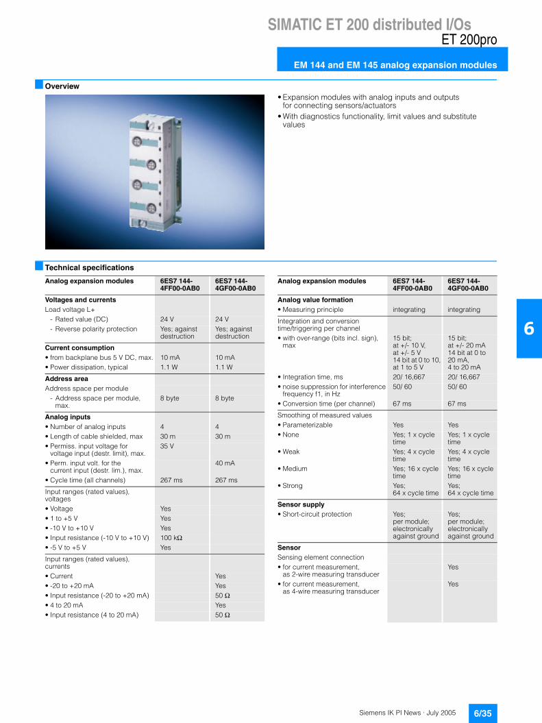
Siemens IK PI News · July 2005 6/35
SIMATIC ET 200 distributed I/OsET 200pro
EM 144 and EM 145 analog expansion modules
6
Overview
• Expansion modules with analog inputs and outputs for connecting sensors/actuators
• With diagnostics functionality, limit values and substitute values
Technical specifications
Analog expansion modules 6ES7 144-4FF00-0AB0
6ES7 144-4GF00-0AB0
Voltages and currents Load voltage L+
- Rated value (DC) 24 V 24 V- Reverse polarity protection Yes; against
destructionYes; against destruction
Current consumption • from backplane bus 5 V DC, max. 10 mA 10 mA• Power dissipation, typical 1.1 W 1.1 W
Address area Address space per module
- Address space per module, max.
8 byte 8 byte
Analog inputs • Number of analog inputs 4 4• Length of cable shielded, max 30 m 30 m• Permiss. input voltage for
voltage input (destr. limit), max.35 V
• Perm. input volt. for the current input (destr. lim.), max.
40 mA
• Cycle time (all channels) 267 ms 267 ms
Input ranges (rated values), voltages• Voltage Yes• 1 to +5 V Yes• -10 V to +10 V Yes• Input resistance (-10 V to +10 V) 100 kΩ• -5 V to +5 V Yes
Input ranges (rated values), currents• Current Yes• -20 to +20 mA Yes• Input resistance (-20 to +20 mA) 50 Ω• 4 to 20 mA Yes• Input resistance (4 to 20 mA) 50 Ω
Analog expansion modules 6ES7 144-4FF00-0AB0
6ES7 144-4GF00-0AB0
Analog value formation • Measuring principle integrating integrating
Integration and conversion time/triggering per channel• with over-range (bits incl. sign),
max15 bit;at +/- 10 V, at +/- 5 V 14 bit at 0 to 10, at 1 to 5 V
15 bit; at +/- 20 mA 14 bit at 0 to 20 mA, 4 to 20 mA
• Integration time, ms 20/ 16,667 20/ 16,667• noise suppression for interference
frequency f1, in Hz50/ 60 50/ 60
• Conversion time (per channel) 67 ms 67 ms
Smoothing of measured values• Parameterizable Yes Yes• None Yes; 1 x cycle
timeYes; 1 x cycle time
• Weak Yes; 4 x cycle time
Yes; 4 x cycle time
• Medium Yes; 16 x cycle time
Yes; 16 x cycle time
• Strong Yes; 64 x cycle time
Yes; 64 x cycle time
Sensor supply • Short-circuit protection Yes;
per module; electronically against ground
Yes; per module; electronically against ground
Sensor Sensing element connection• for current measurement,
as 2-wire measuring transducerYes
• for current measurement, as 4-wire measuring transducer
Yes
Siemens IK PI News · July 20056/36
SIMATIC ET 200 distributed I/Os
EM 144 and EM 145 analog expansion modules
ET 200pro
6
Technical specifications (continued) Ordering data Order No.
A) Subject to export regulations: AL: N and ECCN: EAR99H
Analog expansion modules 6ES7 144-4FF00-0AB0
6ES7 144-4GF00-0AB0
Error/accuracies • Linearity error
(relative to the input range)+/- 0.01 % +/- 0.01 %
• Temperature error (relative to the input range)
+/- 0.002 %/K +/- 0.002 %/K
• Crosstalk between the inputs, min. -50 dB -50 dB• Repeatab. in the settled state
at 25°C (rel. to output range)+/- 0.025 % +/- 0.025 %
Operational limit in the entire temperature range• relative to the input range,
voltage+/- 0.15 %
• relative to the input range, current
+/- 0.15 %
Basic error limit (operational limit at 25 °C)• relative to the input range,
voltage+/- 0.1 %
• relative to the input range, current
+/- 0.1 %
Interference voltage suppression for f = n x (fl +/- 1 %)• Series-mode interference (peak
value of interference < rated value50 dB 50 dB
• Common-mode interference (USS < 2.5 V) , min.
70 dB; interfer-ence voltage < 5 V
70 dB; interfer-ence voltage < 5 V
Status information/ interrupts/ diagnostics Interrupts• Diagnostic interrupt Yes; parameter-
assignableYes; parameter-assignable
• Limit value interrupt Yes Yes• Process interrupt Yes; (limit value
interrupt), parameter-assignable for channel 0
Yes; (limit value interrupt), parameter-assignable for channel 0
Diagnostics• Diagnostics Yes• Wire break Yes;
at 1 to 5 VYes; at 4 to 20 mA
• Short circuit Yes; at 1 to 5 V
Yes; at 4 to 20 mA
• Group error Yes
Diagnostic display LED• Group fault SF (red) Yes Yes
Isolation • Isolation tested with 500 V DC 500 V DC
Galvanic isolation Analog output functions• between the channels No No• between the channels and the
backplane busYes Yes
Permissible potential difference • between the inputs and MANA
(UCM)5 Vpp AC 5 Vpp AC
• between MANA and Minternal (UISO)
500 V DC 500 V DC
Dimensions and weight • Weight, approx. 150 g 150 g• Width 45 mm 45 mm• Height 130 mm 130 mm• Depth 35 mm 35 mm
4AI U analog input module A 6ES7 144-4FF00-0AB0High Feature, ±10 V; ±5 V; 0 to 10 V; 1 to 5 V, channel-specific diagnostics, including bus module. Connecting module must be ordered separately
4AI I analog input module A 6ES7 144-4GF00-0AB0High Feature, ±20 mA; 0 to 20 mA; 4 to 20 mA, channel-specific diagnostics, including bus module. Connecting module must be ordered separately
4AO U analog output module A 6ES7 145-4FF00-0AB0High Feature, ±10 V; 0 to 10 V; 1 to 5 V, channel-specific diagnostics, including bus module. Connecting module must be ordered separately
4AO I analog output module A 6ES7 145-4GF00-0AB0High Feature, ±20 mA; 0 to 20 mA; 4 to 20 mA, channel-specific diagnostics, including bus module. Connecting module must be ordered separately
Accessories
CM IO 4 x M12 connecting module
A 6ES7 194-4CA00-0AA0
4 M12 sockets for connecting digital or analog sensors oractuators with ET 200pro
Module identification labels 6ES7 194-4HA00-0AA0For color coding of the CM IOs in the colors of white, red, blue and green; pack with 100 units each
M12 covering cap 3RX9 802-0AA00For protection of unused M12 connections with ET 200pro

Siemens IK PI News · July 2005 6/37
SIMATIC ET 200 distributed I/OsET 200pro
PM-E power module
6
Overview
• PM-E 24 V DC power module
Application
The PM-E 24 V DC power module is used for supplementary supply or division into groups of the 24 V load voltage for elec-tronics modules within an ET 200pro station.
The following module is available:• PM-E 24 V DC (available soon)
PM-E connection module (must be ordered separately):• CM PM-E direct (with up to 2 M20 cable glands)• CM PM-E ECOFAST Cu (with one ECOFAST Cu connection)• CM PM-E 7/8“ (with one 7/8“ female connector)
Ordering data Order No.
A) Subject to export regulations: AL: N and ECCN: EAR99H
PM-E 24 V DC power module A 6ES7148-4CA00-0AA0For backfeed and group formation of the 24 V DC load supply for electronic modules within an ET 200pro station.
Accessories
CM PM-E ECOFAST connecting module
A 6ES7 194-4BA00-0AA0
For backfeed of 24 V load volt-age, 1 ECOFAST Cu connection
CM PM-E direct connecting module
A 6ES7 194-4BC00-0AA0
For backfeed of 24 V load voltage, up to 2 M20 screwed cable glands
CM PM-E 7/8" connecting module
A 6ES7 194-4BD00-0AA0
For backfeed of 24 V load voltage, 1 x 7/8"
Spare fuse A 6ES7 194-4HB00-0AA012.5 A quick-response, for interface and power modules, 10 items per package unit
Accessories for CM PM-E ECOFAST
PROFIBUS ECOFAST hybrid connector 180ECOFAST Cu, 2 x Cu, 4 x 1.5 mm2, HANBRID connector
• with male insert, 5 per pack 6GK1 905-0CA00
• with female insert, 5 per pack 6GK1 905-0CB00
PROFIBUS ECOFAST hybrid connector angularECOFAST Cu, 2 x Cu, 4 x 1.5 mm2, HANBRID connector
• with male insert, 5 per pack 6GK1 905-0CC00
• with female insert, 5 per pack 6GK1 905-0CD00
Accessories for CM PM-E direct
Power cables 6XV1 830-8AH105-core, 5 x 1.5 mm2, trailing type, sold by the meter, minimum order quantity 20 m, maximum order quantity 1,000 m
Accessories for CM PM-E 7/8"
7/8" connecting cable to power supply5-core, 5 x 1.5 mm2, trailing type, pre-assembled with two 7/8" connectors, 5-pin
• 1.5 m long 6XV1 822-5BH15
• 2.0 m long 6XV1 822-5BH20
• 3.0 m long 6XV1 822-5BH30
• 5.0 m long 6XV1 822-5BH50
• 10 m long 6XV1 822-5BN10
• 15 m long 6XV1 822-5BN15
7/8" cable connectorWith axial cable outlet
• with male insert, 5 per pack 6GK1 905-0FA00
• with female insert, 5 per pack 6GK1 905-0FB00
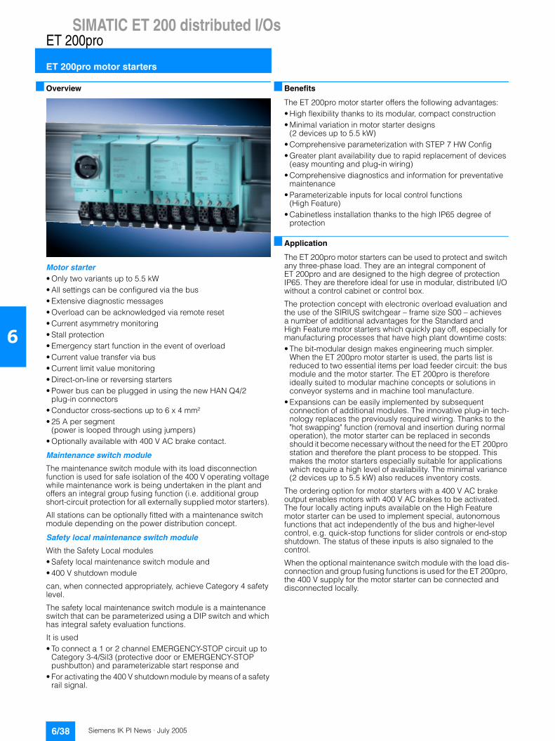
Siemens IK PI News · July 20056/38
SIMATIC ET 200 distributed I/Os
ET 200pro motor starters
ET 200pro
6
Overview
Motor starter• Only two variants up to 5.5 kW• All settings can be configured via the bus• Extensive diagnostic messages• Overload can be acknowledged via remote reset• Current asymmetry monitoring• Stall protection• Emergency start function in the event of overload• Current value transfer via bus• Current limit value monitoring• Direct-on-line or reversing starters• Power bus can be plugged in using the new HAN Q4/2
plug-in connectors• Conductor cross-sections up to 6 x 4 mm²• 25 A per segment
(power is looped through using jumpers)• Optionally available with 400 V AC brake contact.
Maintenance switch module
The maintenance switch module with its load disconnection function is used for safe isolation of the 400 V operating voltage while maintenance work is being undertaken in the plant and offers an integral group fusing function (i.e. additional group short-circuit protection for all externally supplied motor starters).
All stations can be optionally fitted with a maintenance switch module depending on the power distribution concept.
Safety local maintenance switch module
With the Safety Local modules• Safety local maintenance switch module and• 400 V shutdown module
can, when connected appropriately, achieve Category 4 safety level.
The safety local maintenance switch module is a maintenance switch that can be parameterized using a DIP switch and which has integral safety evaluation functions.
It is used• To connect a 1 or 2 channel EMERGENCY-STOP circuit up to
Category 3-4/Sil3 (protective door or EMERGENCY-STOP pushbutton) and parameterizable start response and
• For activating the 400 V shutdown module by means of a safety rail signal.
Benefits
The ET 200pro motor starter offers the following advantages:• High flexibility thanks to its modular, compact construction• Minimal variation in motor starter designs
(2 devices up to 5.5 kW)• Comprehensive parameterization with STEP 7 HW Config• Greater plant availability due to rapid replacement of devices
(easy mounting and plug-in wiring)• Comprehensive diagnostics and information for preventative
maintenance• Parameterizable inputs for local control functions
(High Feature)• Cabinetless installation thanks to the high IP65 degree of
protection
Application
The ET 200pro motor starters can be used to protect and switch any three-phase load. They are an integral component of ET 200pro and are designed to the high degree of protection IP65. They are therefore ideal for use in modular, distributed I/O without a control cabinet or control box.
The protection concept with electronic overload evaluation and the use of the SIRIUS switchgear – frame size S00 – achieves a number of additional advantages for the Standard and High Feature motor starters which quickly pay off, especially for manufacturing processes that have high plant downtime costs: • The bit-modular design makes engineering much simpler.
When the ET 200pro motor starter is used, the parts list is reduced to two essential items per load feeder circuit: the bus module and the motor starter. The ET 200pro is therefore ideally suited to modular machine concepts or solutions in conveyor systems and in machine tool manufacture.
• Expansions can be easily implemented by subsequent connection of additional modules. The innovative plug-in tech-nology replaces the previously required wiring. Thanks to the "hot swapping" function (removal and insertion during normal operation), the motor starter can be replaced in seconds should it become necessary without the need for the ET 200pro station and therefore the plant process to be stopped. This makes the motor starters especially suitable for applications which require a high level of availability. The minimal variance (2 devices up to 5.5 kW) also reduces inventory costs.
The ordering option for motor starters with a 400 V AC brake output enables motors with 400 V AC brakes to be activated. The four locally acting inputs available on the High Feature motor starter can be used to implement special, autonomous functions that act independently of the bus and higher-level control, e.g. quick-stop functions for slider controls or end-stop shutdown. The status of these inputs is also signaled to the control.
When the optional maintenance switch module with the load dis-connection and group fusing functions is used for the ET 200pro, the 400 V supply for the motor starter can be connected and disconnected locally.
Siemens IK PI News · July 2005 6/39
SIMATIC ET 200 distributed I/OsET 200pro
ET 200pro motor starters
6
Technical specifications
Motor starter Standard DSe, RSe
Motor starter High Feature DSe, RSe
General dataMotor starters that can be connected to ET 200pro or modules 110 mm in width
Max. 8
Mounting dimensions(W x H x D) in mm• Direct starter and reversing starter 110 x 230 x 150
Permissible ambient temperature• Operation -25 °C to +55 °C, above +40 °C with derating• During storage -40 °C ... +70 °C
Permissible mounting position Vertical, horizontal
Vibration resistance in accordance with IEC 60068, Part 2-6
2 g
Shock resistance in accordance with IEC 60068, Part 2-27
Half-sine 15 g/11 ms
Current consumption• From auxiliary circuit L+/M (U1) Approx. 40 mA• From auxiliary circuit A1/A2 (U2) Approx. 200 mA
Rated operating current for power bus Ie
25 A
Rated operating voltage Ue 400 V
Approval DIN VDE 0106, Part 101 up to 500 V
Acc. to CSA and UL up to 600 V
For conductor cross-sections• Power infeed max. 6 x 4 mm2
Degree of protection IP65
Touch protection Safe against finger touch
Degree of contamination 3, IEC 60664 (IEC 61131)
Rated impulse withstand voltage Uimp
6 kV
Rated insulation voltage Ui 400 V
Rated operating current for starter Ie• AC-1/2/3 at 40 °C
- at 400 V 0.15 to 2.0/1.5 to 12.0 A- at 500 V 0.15 to 2.0/1.5 to 9.0 A
• AC-4 at 40 °C- at 400 V 0,15 to 2,0/1,5 to 4,0 A
Rated short-circuit switching capacity
100 kA at 400 V
Type of coordination according to IEC 60947-4-1
1
Power of three-phase motors at 400 V
Max. 5.5 kW
Utilization categories AC-1, AC-2, AC-3, AC-4
Safe isolation between main and auxiliary conducting paths
400 V, according to DIN VDE 0106, Part 101
Mechanical endurance of contactor 30 million operating cycles
Electrical endurance of contactor Up to 10 million operating cycles; depending on the current load (see manual)
Permissible switching frequency Depending on the current load, motor run time and relative ON time (see manual)
Switching times at 0.85 to 1.1 x Ue• Closing delay 25 to 100 ms• Opening delay 7 to 10 ms
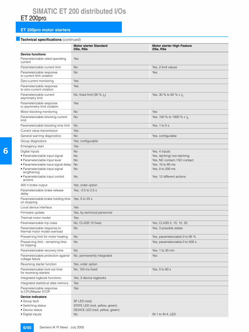
Siemens IK PI News · July 20056/40
SIMATIC ET 200 distributed I/Os
ET 200pro motor starters
ET 200pro
6
Technical specifications (continued)
Motor starter Standard DSe, RSe
Motor starter High Feature DSe, RSe
Device functionsParameterizable rated operating current
Yes
Parameterizable current limit No Yes, 2 limit values
Parameterizable response to current limit violation
No Yes
Zero-current monitoring Yes
Parameterizable response to zero-current violation
Yes
Parameterizable current asymmetry limit
No, fixed limit (30 % Ie) Yes, 30 % to 60 % x Ie
Parameterizable responseto asymmetry limit violation
Yes
Motor blocking monitoring No Yes
Parameterizable blocking current limit
No Yes, 150 % to 1000 % x Ie
Parameterizable blocking time limit No Yes, 1 to 5 s
Current value transmission Yes
General warning diagnostics No Yes, configurable
Group diagnostics Yes, configurable
Emergency start Yes
Digital inputs No Yes, 4 inputs• Parameterizable input signal No Yes, latching/ non-latching• Parameterizable input level No Yes, NC contact / NO contact• Parameterizable input signal delay No Yes, 10 to 80 ms• Parameterizable input signal
lengtheningNo Yes, 0 to 200 ms
• Parameterizable input control actions
No Yes, 12 different actions
400 V brake output Yes, order option
Parameterizable brake release delay
Yes, -2.5 to 2.5 s
Parameterizable brake holding time on stopping
Yes, 0 to 25 s
Local device interface Yes
Firmware update Yes, by technical personnel
Thermal motor model Yes
Parameterizable trip class No, CLASS 10 fixed Yes, CLASS 5, 10, 15, 20
Parameterizable response to thermal motor model overload
No Yes, 3 possible states
Prewarning limit for motor heating No Yes, parameterizable 0 to 95 %
Prewarning limit - remaining time for tripping
No Yes, parameterizable 0 to 500 s
Parameterizable recovery time No Yes, 1 to 30 min
Parameterizable protection against voltage failure
No, permanently integrated Yes
Reversing starter function Yes, order option
Parameterizable lock-out time for reversing starters
No, 150 ms fixed Yes, 0 to 60 s
Integrated logbook functions Yes, 3 device logbooks
Integrated statistical data memory Yes
Parameterizable response to CPU/Master STOP
Yes
Device indicators• Group fault SF LED (red)• Switching status STATE LED (red, yellow, green)• Device status DEVICE LED (red, yellow, green)• Digital inputs No IN 1 to IN 4, LED

Siemens IK PI News · July 2005 6/41
SIMATIC ET 200 distributed I/OsET 200pro
ET 200pro motor starters
6
Selection and Ordering data
1) Functions only in combination with the backplane bus module and the wide rack. The backplane bus module and the wide rack must be ordered separately (see accessories for the ET 200pro motor starters).
Version Order No.
Motor starter Standard mechanical, Motor protection: Thermal model
DSe Standard
Direct starter Dse1)
• without brake output 3RK1 304-57S40-4AA0
• with brake output 400 V AC 3RK1 304-57S40-4AA3
Reversing starter RSe1)
• without brake output 3RK1 304-57S40-5AA0
• with brake output 400 V AC 3RK1 304-57S40-5AA3
Motor starter High Feature mechanical, Motor protection: Thermal model
RSe High Feature
Direct starter Dse1)
• without brake output 3RK1 304-57S40-2AA0
• with brake output 400 V AC 3RK1 304-57S40-2AA3
Reversing starter RSe1)
• without brake output 3RK1 304-57S40-3AA0
• with brake output 400 V AC 3RK1 304-57S40-3AA3
Setting range for rated operating current
• 0.15 ... 2.0 A K
• 1.5 ... 12.0 A L

Siemens IK PI News · July 20056/42
SIMATIC ET 200 distributed I/Os
ET 200pro maintenance switch module
ET 200pro
6
Overview
The maintenance switch module with integral group fusing func-tion (i.e. additional group short-circuit protection for all externally supplied motor starters) is used due to its load disconnection function for safe isolation of the 400 V operating voltage while maintenance work is being undertaken in the plant.All stations can be optionally fitted with a maintenance switch module depending on the power distribution concept.The maintenance switch module is also available in a safety variant. See safety local maintenance switch module.
Benefits
The maintenance switch module boasts the following character-istics:• Greater plant availability due to rapid replacement of devices
(easy mounting and plug-in wiring) • Cabinetless installation thanks to the high IP65 degree of pro-
tection
Technical specifications
Selection and Ordering data
1) Functions only in combination with the backplane bus module and the wide rack. The backplane bus module and the wide rack must be ordered separately (see accessories for the ET 200pro motor starters).
2) The safety local maintenance switch module only operates when combined with the 400 V shutdown module.
Maintenance switch module
General data
Mounting dimensions(W x H x D) in mm• Direct starter and reversing starter 110 x 230 x 170
Permissible ambient temperature• in operation -25 °C ... +55 °C• During storage -40 °C ... +70 °C
Permissible mounting position Any
Vibration resistance in accordance with IEC 60068, Part 2-6
2 g
Shock resistance in accordance with IEC 60068, Part 2-27
Half-sine 15 g/11 ms
Current consumption• From auxiliary circuit L+/M (U1) Approx. 20 mA• From auxiliary circuit A1/A2 (U2) –
Rated operating current for power bus Ie
25 A
Rated operating voltage Ue 400 V
Approval DIN VDE 0106, Part 101 up to 500 V
acc. to CSA and UL up to 600 V
For conductor cross-sections• Power infeed max. 6 x 4 mm2
Maintenance switch module
Degree of protection IP65
Touch protection Safe against finger touch
Pollution degree 3, IEC 60664 (IEC 61131)
Rated impulse withstand voltage Uimp
6 kV
Rated insulation voltage Ui 400 V
Rated operating current for starter Ie• AC-1/2/3 at 40 °C
- at 400 V 25 A- at 500 V 25 A
Rated short-circuit switching capacity
50 kA at 400 V
Type of coordination according to IEC 60947-4-1
2
Safe isolation between main and auxiliary conducting paths
400 V, according to DIN VDE 0106, Part 101
Device functions• Group diagnostics Yes, configurable
Device indicators• Group fault SF LED (red)
Version Order No.
ET 200pro maintenance switch module, mechanical
Maintenance switch module 1)
Rated operating current 25 A 3RK1 304-0HS00-6AA0
Safety local maintenance switch module 1) 2)
Rated operating current 25 A 3RK1 304-0HS00-7AA0
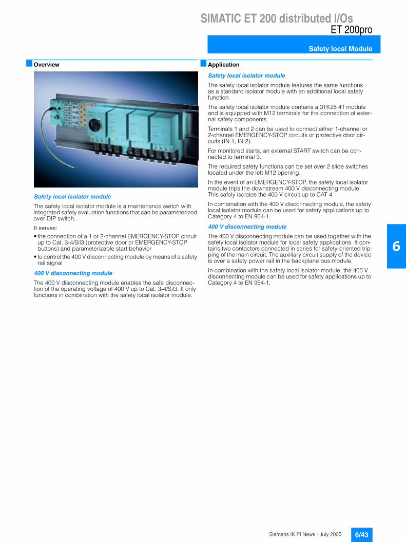
Siemens IK PI News · July 2005 6/43
SIMATIC ET 200 distributed I/OsET 200pro
Safety local Module
6
Overview
Safety local isolator module
The safety local isolator module is a maintenance switch with integrated safety evaluation functions that can be parameterized over DIP switch.
It serves:• the connection of a 1 or 2-channel EMERGENCY-STOP circuit
up to Cat. 3-4/Sil3 (protective door or EMERGENCY-STOP buttons) and parameterizable start behavior
• to control the 400 V disconnecting module by means of a safety rail signal
400 V disconnecting module
The 400 V disconnecting module enables the safe disconnec-tion of the operating voltage of 400 V up to Cat. 3-4/Sil3. It only functions in combination with the safety local isolator module.
Application
Safety local isolator module
The safety local isolator module features the same functions as a standard isolator module with an additional local safety function.
The safety local isolator module contains a 3TK28 41 module and is equipped with M12 terminals for the connection of exter-nal safety components.
Terminals 1 and 2 can be used to connect either 1-channel or 2-channel EMERGENCY-STOP circuits or protective door cir-cuits (IN 1, IN 2).
For monitored starts, an external START switch can be con-nected to terminal 3.
The required safety functions can be set over 2 slide switches located under the left M12 opening.
In the event of an EMERGENCY-STOP, the safety local isolator module trips the downstream 400 V disconnecting module. This safely isolates the 400 V circuit up to CAT 4.
In combination with the 400 V disconnecting module, the safety local isolator module can be used for safety applications up to Category 4 to EN 954-1.
400 V disconnecting module
The 400 V disconnecting module can be used together with the safety local isolator module for local safety applications. It con-tains two contactors connected in series for safety-oriented trip-ping of the main circuit. The auxiliary circuit supply of the device is over a safety power rail in the backplane bus module.
In combination with the safety local isolator module, the 400 V disconnecting module can be used for safety applications up to Category 4 to EN 954-1.
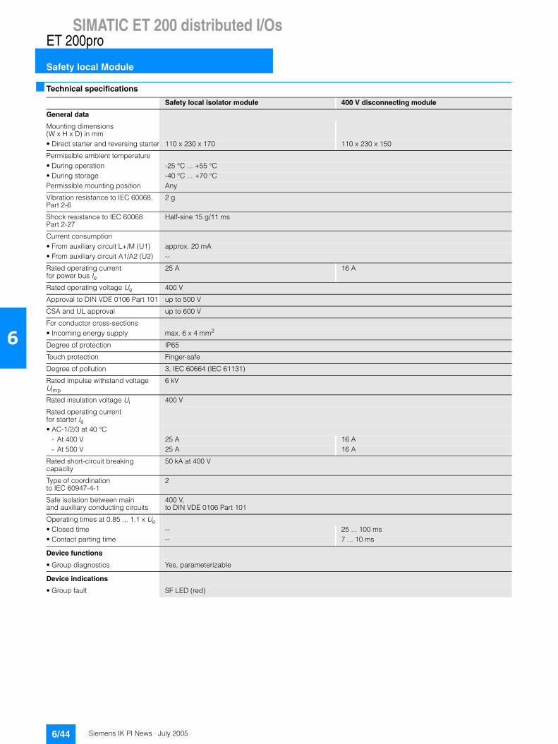
Siemens IK PI News · July 20056/44
SIMATIC ET 200 distributed I/Os
Safety local Module
ET 200pro
6
Technical specifications
Safety local isolator module 400 V disconnecting module
General data
Mounting dimensions (W x H x D) in mm• Direct starter and reversing starter 110 x 230 x 170 110 x 230 x 150
Permissible ambient temperature• During operation -25 °C ... +55 °C• During storage -40 °C ... +70 °CPermissible mounting position Any
Vibration resistance to IEC 60068, Part 2-6
2 g
Shock resistance to IEC 60068 Part 2-27
Half-sine 15 g/11 ms
Current consumption• From auxiliary circuit L+/M (U1) approx. 20 mA• From auxiliary circuit A1/A2 (U2) --
Rated operating current for power bus Ie
25 A 16 A
Rated operating voltage Ue 400 V
Approval to DIN VDE 0106 Part 101 up to 500 V
CSA and UL approval up to 600 V
For conductor cross-sections• Incoming energy supply max. 6 x 4 mm2
Degree of protection IP65
Touch protection Finger-safe
Degree of pollution 3, IEC 60664 (IEC 61131)
Rated impulse withstand voltage Uimp
6 kV
Rated insulation voltage Ui 400 V
Rated operating currentfor starter Ie• AC-1/2/3 at 40 °C
- At 400 V 25 A 16 A- At 500 V 25 A 16 A
Rated short-circuit breaking capacity
50 kA at 400 V
Type of coordination to IEC 60947-4-1
2
Safe isolation between main and auxiliary conducting circuits
400 V, to DIN VDE 0106 Part 101
Operating times at 0.85 ... 1.1 x Ue • Closed time -- 25 ... 100 ms• Contact parting time -- 7 ... 10 ms
Device functions
• Group diagnostics Yes, parameterizable
Device indications
• Group fault SF LED (red)
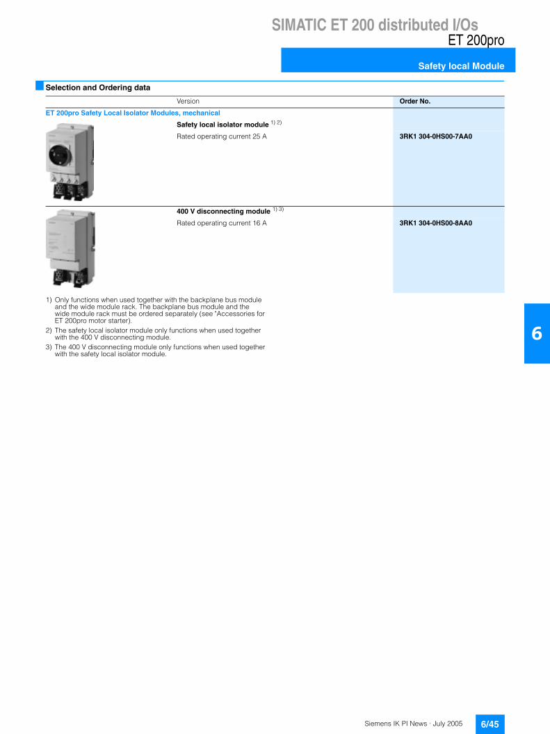
Siemens IK PI News · July 2005 6/45
SIMATIC ET 200 distributed I/OsET 200pro
Safety local Module
6
Selection and Ordering data
1) Only functions when used together with the backplane bus module and the wide module rack. The backplane bus module and the wide module rack must be ordered separately (see "Accessories for ET 200pro motor starter).
2) The safety local isolator module only functions when used together with the 400 V disconnecting module.
3) The 400 V disconnecting module only functions when used together with the safety local isolator module.
Version Order No.
ET 200pro Safety Local Isolator Modules, mechanical
Safety local isolator module 1) 2)
Rated operating current 25 A 3RK1 304-0HS00-7AA0
400 V disconnecting module 1) 3)
Rated operating current 16 A 3RK1 304-0HS00-8AA0
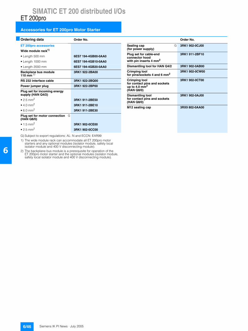
Siemens IK PI News · July 20056/46
SIMATIC ET 200 distributed I/Os
Accessories for ET 200pro Motor Starter
ET 200pro
6
Ordering data Order No. Order No.
G) Subject to export regulations: AL: N and ECCN: EAR991) The wide module rack can accommodate all ET 200pro motor
starters and any optional modules (isolator module, safety local isolator module and 400 V disconnecting module).
2) The backplane bus module is a prerequisite for operation of the ET 200pro motor starter and the optional modules (isolator module, safety local isolator module and 400 V disconnecting module).
ET 200pro accessories
Wide module rack1)
• Length 500 mm 6ES7 194-4GB00-0AA0
• Length 1000 mm 6ES7 194-4GB10-0AA0
• Length 2000 mm 6ES7 194-4GB20-0AA0
Backplane bus module 110 mm 2)
3RK1 922-2BA00
RS 232 interface cable 3RK1 922-2BQ00
Power jumper plug 3RK1 922-2BP00
Plug set for incoming energy supply (HAN Q4/2)
• 2.5 mm2 3RK1 911-2BE50
• 4.0 mm2 3RK1 911-2BE10
• 6.0 mm2 3RK1 911-2BE30
Plug set for motor connection (HAN Q8/0)
G
• 1.5 mm2 3RK1 902-0CE00
• 2.5 mm2 3RK1 902-0CC00
Sealing cap (for power supply)
G 3RK1 902-0CJ00
Plug set for cable-end connector hood with pin inserts 4 mm2
3RK1 911-2BF10
Dismantling tool for HAN Q4/2 3RK1 902-0AB00
Crimping tool for pins/sockets 4 and 6 mm2
3RK1 902-0CW00
Crimping tool for contact pins and sockets up to 4.0 mm2 (HAN Q8/0)
3RK1 902-0CT00
Dismantling tool for contact pins and sockets (HAN Q8/0)
3RK1 902-0AJ00
M12 sealing cap 3RX9 802-0AA00