distributed by: national technical informatio; · it -jpp4lcmcntary 140tus 12 sponsorin' milfl...
TRANSCRIPT

AD-770 852
AERODYNAMICS OF GUIDED AND UNGUIDEDWEAPONS. PART 1. THEORY AND APPLICATTON
Frank G. Moore
Naval Weapons LaboratoryDahlgren, Virginia
December 1973
4`I-
DISTRIBUTED BY:
National Technical Informatio; ZrviceU. S. DEPARTMENT OF COMMrIRCE5285 Port Royal Road, Springfield Va. 22151

UI4L~LA-ZittU WOW_____
"DOCUMENT CONTROL DATA - R & D- po A , I A • W1t. .r I ?,rC rfv, d.. .,luht the - crll Ap6,,, (Id h
JUNCLASSI FIEDL[ Naval Weaporns LaboratoryS• ahigren, Virginia 22448 J
REP _ _ _ _ _ __ORT TITL Ir _
AERODYNAHIICS OF GUIDED fo'D UNGUIDED IEAPONS, PART 1 - THEORY AND APPLICATIONl-~~~ f %(k# £SCITIVE NO TES (Type o~f ep.'l ar..1IincIla'aVe daties)-
Atf "PiOR6SI (FIrMI nIun•A. middle ini.,tie,. to "1 nalme)
Frank G. Moore0. Rt POR t rý NTE 70 OA NQPA GCS ybt 140 CF- nciS
December 1973 _
Rd CON TR~A-T OR GRANT NO 90. ORiG.NATOR'S REP~ORT I4UMI<.GNIS
b PROjEZ NO
NWL TP-3018'? 'lb. Ot 'R R�I'OR T NO(MI (Aty outher ,iunilb.r& tlat ntha h- nss,iln.d
thus report)
1O OISTRIIIUTION SrATCMENT
Approved for public release; distribution unlimited.it -jPP4LCMCNTARY 140TUS 12 SPONSORIN' MILfl ARY A. 11VI TY
i W A1•TIA C T
Several theoretical dnd empirical procedures are combined into a single computerprogram to predict lift, drag, and center of pressure on quite general wing-bodygeometries. The metnod is applicable for Hach number zero to three and angle-of-attack zero to about fifteen degrees. Computed results for several configurationscompare well with experimental and other analytical results. It costs about fivedollars per Hadh number to compute the static aerodynamics of a typical winp-bodyshape on the CDC 6700 computer.
NATIONAL TECHNICALINFORMATION SERVICE
FORM 1473 (IA'"-)S...."" " / UFIEP.• , t|102.oI4.67T oi x!' f tl tv (1''1' • , .. . .

NWL Technical Report No. TR-3018December 1973
__ AERODYNAMICS OF GUIDED ANDUNGUIDED WEAPONS
PART I - THEORY AND APPLICATION
by
Frank G. Moore/ Surface Warfare Department ) C
DEC u14 1
Approved for pubtic release; distribution unlimited.
•Mt,,'4,
K ,*- 2
Vr
1FOREWORD
This work was performed to provide a design tool for use in estin ,,g the
aerodynamics of guided and unguided projectiles. Support for the' wt,'k w- p,•ovidedby the Naval Ordnance Systems Command un'er ORDTASK 35A-f3l ',t.-I/UF32-323-505.
The current report was reviewed and approved by Mr. 1). A. Jones, ill, Ukadof the Aeroballistics Group and by Mr. C. A Cooper, Head of the GuiO 1 ProjectileDivision.
Released by:
R. L TOPPIIN(;. DI-R, LISNAssistant Head. Suface
Warfare Depaimet
q(,
,%

ABSTRACT
Several theoretical and empirical procedures are combived into a singlc
computer program to predict lift drag, and center of pressure on luite generalvwing-body georletries. File method is applicable f7or Mach number /ero to three and
ifangle-w'-attack zero to about fifteen degrees. Computed results for severnlconfitinrations compare well with experimental and other analytical results. It costsabout five dollars per Mach number to compute the static aerodynamics of a typiialwing-body shape on the CDC 6700 comptuter.
'F
-II
',

CONTENTS
Page
FOREW O RD .. .. . . . . . . . . . . .. . .. . . . . . . . . . .. . . . .. . . .X\BSTRACI . .. . . .. . . . . . .. . . . .. . . . . . . . . . .. . . . . . . . . iiI. INTRODUCI'ION .. ............................... IIt. ANA LYSIS . . . . . . . . . . . . . . . . . . . . . . . . . . . . . . . . . . . . ,1
A. Body Alone Aerodynamics .................. ....... 4B. Tail or Canard Drag ............................ 4
1. Wave Drag ....... ............................... 62. Skin-Friction Drag ........ ........................... 203 Trailing Edge Separation Drag ...... .................... 214. Ba.se Pressure Drag Due
to Presence of' Fins ............................... 23C. Tail or Canard Alone Lift. ......................... 26
1. Subsonic Flow ........ ............................. 262. Supersonic Flow ........ ............................ 303. Transonic Flow ........ ............................ 37
1D. Interference Lift ......... .............................. 4!E. Summary Configumation ........ ........................... 52
I11. RESULTS AND DISCUSSION ................................. 55A. Comparison With Exact Linear Theory .................. 55
I Wing Wave Drag ........ ............................ 552. Wing Lift ........ ................................ 61
B. Comparison With Experiment ............................... 67"C. Computational rime and Cost ............................. 75
IV, CONCLUSIONS ........ ................................. 7(R!,FI:RENCES ............................................. .. 7APPENNDICLS
A Geometry for Blunt Leading Edge Wing13. Newtonian Wave Drag Coefficient of Blunt
Leading, Edge WingC. Trailing Idge Separation DragD. GlossaryL. Distributior,
Ti'
•-'t 111

LIST OF FIGURES
Figure Page
1. Basic Configurations ...................... ....... 32. Methods Used to Compute Body Alone Aerodynamics .............. 53A. Wing With Modified Double Wedge Airfoil Section ..... ............ 73B. Wing With Biconvex Airfoil Section .......................... 84. Subsoaiic Scurce or Sink Line ..... ........................ .5. Supersonic Source or Sink Line....................... 136. Linear Superposition of Triangular Source
- and Sink Distributions .................................. 157. Combined Newtonian and Perturbation Theory for
a Blunt Leading Edge .................................. 198. 2-D Base Pressure Coefficients .................... ... 229. Base Pressure Coefficient Change With Fins
Located Flush With Base ...... .......................... 2410. Distance From Base Where Fins Do Not
Affect Base Pressure ................................... 25I IA. Flat Plate Wing Planform With Supersonic Leading and Trailing Edges;
Mach Line Intersects Wing Trailing Edge. ..................... 311 liB. Flat Plate Wing Planform With Supersonic Leading and Trailing Edges;
Mach Line Intersects Wing Tip ............................ 332. Flat Plate Wing Planform With Subsonic Leading Edge and
Supersonic Yraiihig Edge........................3513. Transonic Force-Break Mach Number .................... 3914. Charts for Determining Transonic Lift Curve Slope at M11and Mb .... 4015. Slender Body jmterference Lift Factors ..... ................... 4416. Determination of KlB(w) for High-Aspect-Ratio Rar'ge at
Supersonic Speeds ................................... 4517. Procedure Used t( Calculate Interference Lift for
Wings With Swept Back Trailing Edges When.Slender Body Theory Is Used ..... ....................... 49
18. Methods Used to Compute Wing Alone and Interference Aerodynamics 5,4I19. Pressure Distribution Along the Span of a Sweptback Wing With a
Symmetrical Circular Arc Airfoil;A = 60', M,, = 1.4, ct/c 1 = 1 ...................... 56
20. Spanwise Wave Drag Distribution on Wing WithDouble Wedge Airfoil Section;SA 6.92, M, 1.414, Ci/cr =0 ...... ................... 57
tq

LIST OF FIGURES (Continued)
Figure Page
21, Spanwise Wav,' Drag Distribution on Wing WithDouble Wcdge Airfoi; Section:PR = 3.26, M. = 1.414. cl/c. 0.5....... ................ 58
22. Wave Drag of" Wing With Double Wedge Airfoil Section,-" cri = 1.0 ........ ................................. .59
23. Wave l)rag uf Wing With Biconvex Airfoil Section:ct/cr = ................................. 60
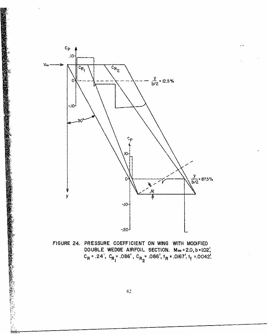
24. Prtssure Coefficient on Wing WithModified I)ouble Wedge Airfoil Section.M, 2.. b = 0.92' c, = 0.28', Ci= 0.086'.cr 2 = 0.0810', L" 0.0167', 0.0042' ...................... 62
25. Zero Lift Drag of Wings, as a Function of Leading Edge Bluntness;-R= 2. AI A 4 =100 . 0.12..... .................... 63
26. Wing, With Subsonic Leading and Supersonic T.ailing Edge 6427. Wing With Supersonic Leading and Trailing Edges;
Mach Line, Intersects Trailing Edge ........................... 6528. Wing With Supersonic Leading and Trailing Edges;
Mach Line Intersects Tip ....... ......................... 6029. Aerod. namics of' a Missile Configuration;
A zR = 1.0, A I Z.... 1 Ž, = 0.5. o = ........................ 68
S30A. Arodynamics of a Mhssile Configuration:AR = 2.0, A = 0 j\ . ..O, .= ..................... 69
30B. Aerodynamics of a Missile Configuration;R = 2A, =0 X= 1.0A M- = 1.3 ...... .................. 70
31A. Normal Force and Center of Pressure of a Missile Configuration;R't = 4, ARc = 2, M_ = 16,6 ....... ...................... 72
31lB. Drag of a Missile Configuration and Its Components ................ 7,31C. Pressure Coefficient on Leading Edge of a Blunt Leading Edge Wing;
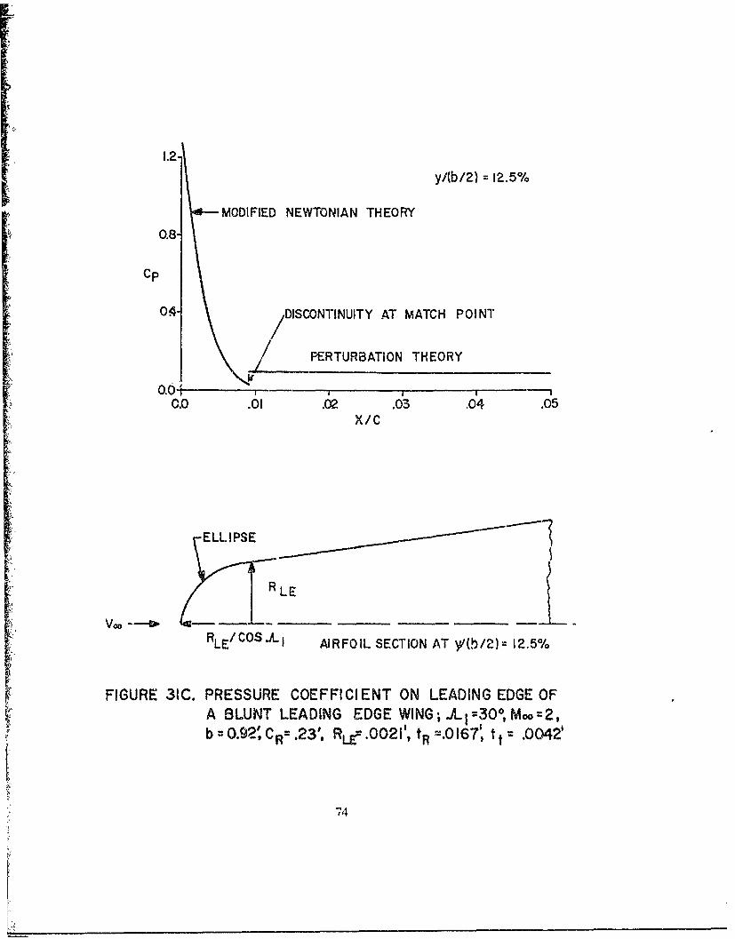
\A= 300. M 2, 1 = 0.92', cr = 0.23'rL'. t = 0.167', I .0042't. .............. 74
0
.
"4*,

1. INITRODUCTION
I'lle geal of (lhe pror,-ent rcsvarh is to dc:veloj) the capaibility to compute staticaerodlyn,.umics onconfiguirations sukh js guided anid uhguided projjectiles for the Machinumber range ;ero to thiree and angle-of-at tack range 7ero to about twenty degrues.The Machi number and a ngleý-o fat tack, range cover a nmajority of' present andprobable fuiture design requir.Žnents foi gun latinchied weap~ons. Thswrkrhreoeis a naimla1 extension to the bodx alone aerodynamic prediction methodologydevelored in Reference 1. Induded hiercin is an outline of tile theorctital and[empirical methods used to .ompute lift, drag, i~nd pitching moment on wings and,tails. Also included arc procedures to dtirermine thle various interference effectswhich occur betweci the wiiig-til or body,-tail. A description and listing of theentire wirg-bodN coniifl~er program will appear &,~ part If oif this report.
The ove~rall Iguiding principle of' the current work is to use aiiaIl tical methodswhich yield reasonable accrciesv, ;md iequire reasonable computational time. Forareas where the state-ol-the-art is such that analy~tical procedures do not meet theabove requirements on accuracy aind c:ost. empirical prot-e~ucs are employed. This,problem occurs mainlyv in transonic flow.
Tiere have been several work-, which pertain to the pre.sent probklem Thc, firstor these is that of" SaIflell, et ali 2 whlo devele, ed a computer program to compu)Ltestatic aerodyn~amics on lo%ý aspect ratio missile configuirations, The mlethod could K
appiedforlare agle-of-at tack and ' r subsonic: thi ough supersonic Mach numbers.
However, the (Irag was computed using handbook techniques and thle lift of thewing alone x.as found from in empirical formula for low aspect ralio wings. Thus.drag results ,lie quite biaccura 'e tat ,mall angles-ot-attack ), as well as lift for highaspect ratio contigura tions.
Anotl~er method which is; availade for spin--stabiliied (or body alone) tproJeetilesis the GE 'Spniiier .program.' -, This programn. wh~ich is compleitely empirical, givesgood results for most stand..-d shaped proje~tiles but is too limited ill scope tomeet the present needs.
The most detailed method of those previously available is that otf "Woodward.4
Woodward uses perturbatioo theoiy to coniput- (lth- pressure distribution onwing-body combinations in ,uhbsomt. and] tipersonik. flow. I-howevcr, the bodies mustbe pointed and the wing leading edge sharp Also, hie does not calculate thle baseandl skin-friction drag or the non-linear a ngle-o f-at "ack effects.
As is apparcnt i rom fihe ahiwv, dicsctin~n. i~one oft thie p w'xiows works canl initself accuratcly compotil totalI lift. draig. w~d pi tchiing, momei onl xing-body

combinations for Mach numbers 0 to 3, and angles-of-attack 00 to 200. Moreover,no attempt is made to handle the complicated body and wing geometries (seeFigure 1) which arise fiom gun !aunched guided weapons.
!.2

a. SPIN STA31LIZED PROJECTILE
b. UNGUIDEY FIN- STABILIZED ?ROJECTILE
c. GUIDED FIN-STABILIZED PROJECTILE
FIGURE 1. BASIC CONFIGURATIONS (ILLUSTRATION ONLY)
3

H. ANALYSIS
The ir-nroacli ,)f thle pi eseni work is to break thle missile ciifiptlra tionl downinto it's indm diwl comlponenfts tomposed of body alone. will,,. and Canards al,-dtheln to account separatek for tile varlow., intlerferonce effects. '1hw, is opposed toiiijat~icautiýai1 illodelling the entire C~iIIlufdlri0 Sill lltWON sinlaio is , as X (10111do! in thlewvork of Woodi aid 14 Woodvward ton.idcred lthe w'ing-hodh %inlultaneotisly thirouighan appropriate souR e and dink(lsribmli,,n, where the sourcte. f rom thle body Wvere:Jlowed to intlue-Ce thle %vwiii solution and vix: vcrsa. This i-. lairl% straightforwardfor poinlted Hnoed bOdItes aod Wing~s with sharp leading edges. blit for bilunt nosecdbodies and blunt leading cdige wing'as, a', i' thilae ill thle pr.:\et wvorl<, thleproblem is coimplicated coiisidvrablý. Niorýover, assumtiing, perllurkaiw to . thorie, areýus,ýed to Calculate thie inl iscid aerod) namii&. flie approach Of osdrn theindividual coilpolen ts separa telV sho01n 1,1yi1d total forces and momeniit which -,i e as1good as those: that would bc obtmined bk Considering the tol fnigurallonl as a whole.
A. Blody Alone Acrodyliami~s
Thle l'odv alolic aerod% namiic anvhlYsis appears inl ke,"vienL e I and will notbe repeated hiere. However. a sUn11.udrNv Of the various miethods for computing b)odyalone aerodv namllcs appemrs in1 Figure 2. All thie methods me %lam, rd in theliterature ( References 5 throughi 10) With thW e\ce~tiOn o1' tile emllpirical schlemesderived for transonic lif't and \,.avc drag and thie combined NewNIt oniaat-pertuirbaaI~on
Ctheory for calcula ting nose wave di1a11 inl Supersonic I low\ The combinedNewt onia n-,er uirba Iion theory v. as dleveloped so teasoll'Ible iesulis for staticlerodynam,,% could be obtained at low -supersonic Maclh iiunioo'i fob r blunt nosedconfiguratioi~s. Previously, the aui aba e theeories% were cithei too JInL11Ai uie'' 1) 01o too
complicated' 1 2 1 for use at the lower end of the Nupers-nik IMacli ranizc
B. Tail or Canard Drag
As in the case of' ,n h ~mci ody, thie the%\n, 'it~ ing, dima,isý comlposed of wave, skin-friction1, and a I railing edge separation dri- it' (ifte tradlingeýdge is bluint Or ilhe rear sctioii of' tiL' .111 oil has a lar-e slope ho,. trailing edgeýseparationl drag 1, anlalogou% it) base pre-aure dragy on at bod\ oI tevolutioti. Illaiddition to these drag cornponoci1 The \vings Call cauise anl addlilio nal drag froiukbody base pressure changes dute tip the plteseice of' 6,n1. Fach of 1these wing drag,Components \01il be treated eCpalatdv , ;,doxx
4

~ a:. 0
a -) > - 0 w LLL. Cl)
()cc~j >1 Z C'Cjj o 0 W
o<
Z 0 0 0 i0 >- H >-0
Zl C )w1
< y -0 WW w a
< w>H
0 < 0
m L)
tw2 000
LUx Z z
0 W:~ Wf± :c%
(I) z 2
0 0L 0 J.- (IoL Z__ C'w
z >) L

4
1. Wave Drag
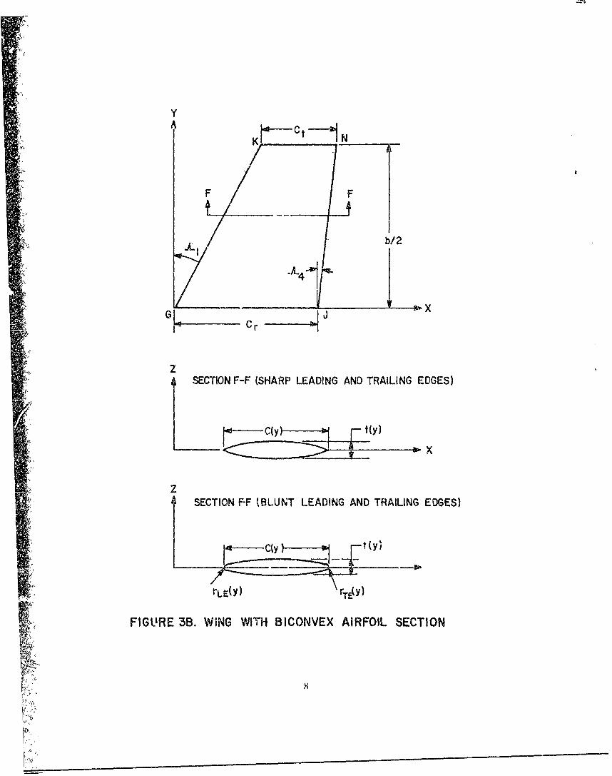
It will be assumed apriori that the wing is symmetric at ,ut the x-yplane so that no ... "ber is present. Furthermore, the wing will be assumed to beth n wuh either a modified double wedge (Figure 3A) or biconvex airfoil section(Figure 3B). However, by assuming a modified doubte wedge only requires thatstraight lines exist between points A and B, B and D, and D and E (seeFigure 3A). These straigiht lines could then be any percentage of tile entire chord.For example, if BD were zero the airfoil would be a double wedge design or ifboth BD and DE were ze;o, the airfoil would be a wedge. Also, either the biconvex1o modified Jouble wedge design may have blunt leading and trailing edges and the
thickness to chord "atio may ,,ary along the span. The wing ge ierators GK, HL, IM,and JN are assumed straight.
Siirce the wing is thin, the linearized three-dimensional equation ofmotion governing the steady flow field is:(13)
g2o6 - -y Y = 0 (I)
wlere subscripts indicate partial differentiation. Here, the velocity potential O isiclated to the perturbation velocities by:
X= u(2a)
= v (2b)
w (2c)
lhli boundary conditions required for the solution of the linear partial differentilI quation 01) are that the fl - must be tangent to the surface:
w(xy) = OZ(Xýy. 0" (Xy,0 (x,y) (3)ax
and that the perturbation velocities must vanish upstreain oý the most forward pointA tile wing. Referring to Figure 3A, this most forward po;nt is at x 0 so thattle second boundary condition is:
6

y
K L- M N
SF F
b/2_ 4
G [ 2 I _ _ _ _
Cr 2 H Cr
"Cr-
Z SECTION F-F (SHARP LEADING AND TRAILING EDGES)
B D
B Z
Z SECTION F-F ( BLUNT LEADING AND TRAILING EDGES)
SFLL•Y rC(YY
FIGURE 3A. WING WITH MODIFIED DOUBLE WEDGEAIRFOIL SECTION
c m.
KY
F F
LI b/2
G I x xC r
zSECTION F-F (SHARP LEADING AND TRAILING EDGES)
i SECTION F-F (BLUNT LEADING AND TRAILING EDGES)
LC(yy r t (y)
FIGURE 3B. WiNG WITH BICONVEX AIRFOIL SECTION

9(U-; -- ,;,/1 = 6 -,y,z) = 0 (4)
[lhc plu'v or minus ,,uper;ript Ime,:w the particula, axis is approached from thepositive or negative side. repccti-' . u),ie to the symnletrnr of the airlolf.hIquation (131 indicates that it make,, no difference rom which side one appioachestile axis I = O.
Equation (1) ks valid only where the perturbation velocities aie small.Thi,. mea,, that in the nelghiborhood of a blunt leading or trailing edge-. ,oni o)tlw.-rm101ethod mnust be applied, Consider first a ,enwil three-dimensional wing with shlrpleading alnd trailing edges.
The general solution to Equation I) along the airfoil suarface (I (1)
is,( 14)
0) - /f"~IA \%'(xl,.il)dxldyI
where ,, indicates the region of integration. The source strength \vwx, y I) is relatedto the 0ocal slope of t(itV airfoil surlace through tile boundary ,Oldition
Eduation (3).
Inh previous works,, w(I NI ) Wassun e C Ol Sconsta or ai utio(111 of x
only (tile slope of the airfoil ' urface Was the same aill along the span), so theintegration of the above integral could be carried out in closed form for siniplcwing plan forms.'l- l In the preent :analysis. the slope of the wing is allo\\ed I')
vary in tile spanwise as well azs the chordwise directionI so C li n e in at ioin ol
Ilqulalion (5) cannot, in gene-ral, be carried out in closed formll. The 1n,,,,tstraightforward method of solution, is then io define the slope of' thle given Siirfaceand carrx out the doube.C integrat ion b, numerical quadrature. However. one muIIbe :iware of the singular nature of tilhe ouble in te-,,lt where (x- \ 1 -- = 371\ \ I)
during tlih inlheera tiopt An, llA he ai terna iw i% to, aSSIn' Ilhi tt oi a nmall
elilleent of tile wing surfaice, W(\I IN) is constant. I iwim . if' the region of ink ri t h• ,of"' Jillatiot i5.) E5). , is al'm llcd to be ovel a s.all elmlent of tile Wing, olle Ina\
;7, write.
n C- x! )- - :(-y- y1)"
K

Equation (to is now in the fornn given in Reference 13 for simple planfonngeometries and flue integration czn be carried out directly. Again: it should beCrilmphasized that w(xyl iS t(ie Slope of thie airfoil surface at a given point and variesfor each el.,ncnt on the wing.
]lhe closed form solutioj! of Equation (6) depends on whether the.-.ing gencritor, are subzoniL or -uperhonic. Referring tn Figure 3A, a subsonic wing
Svenerator wdul.t exist if the Mach number normal to line GK were less thaln oil'miand a supersonic wiaig generator wouid exist if M, > 1. The same applie, to eacnof the other wing generators RL, U.M, and IN. For the biconvex airfoil, Figure 3B. aStonfintios distribution of wing generators is placed between the lines GK and JN.Eadi wing geverator is analogous t( a line of sourccs and sinks with strengths%.ufficieiit to k.-cp the, flow taigent to the surface.
a. Subsonic Source or Sink Line (SOSL)
If the wing generator is subsonic, the induced velocity at a givenlpoint P. due to the SOSL, is dependent on thie location of P relative to the SOSL.Reerring to Figure 4A, if P P1 the induced velocity is:"
2 '~~~iL~i~j2cos;lf 1- 7
where w is dtermined from the bound~ary condition ::nd is (for the airfoil soctio,•at y = YI, I
Wd7\wx1 1 I (IXPt" dx P
InIi lquation (7), the def initions'7)K tan A t 7a)
l"ie betetn kcd If P) P, the induced ve!oity at 1), due to a given SOSL is:
10

'I L
i MACH LINE
SOSL SOSL
FIGURE 4A. TRIANGULAR SURFACE SYMMETRIC ABOUT X AXIS
• P/4 "•JL '1 P4
A P4
WING TIP CHORD
i:" CON1INUATION OF
"
SOSL BEYONDWNTI
WCNG TIP
FIGURE 48. WING TIP EFFECTS
FIGURE 4. SUBSONIC SOURCE OR SINK LINE
I"I

= • - " - c o s i l t u ~
Ai tile wing tip. thcre i., an additional disturbance v.,ithin tile \iach line emamdtiI,.rom tile tihp le:adin, edge (Fig,!'r 4B). The induced velocit\ in this rcgion. P 1
The absolute value of a is taken because a is actually negative for the point IP,Ilhe induced vdocity at any poinIt, say ) = P4" outside of the Mach ilnes enmanati'nromin the beginning of the SOSL is 7ero since ithis point is out of the lone of
•" !,nilueilce.
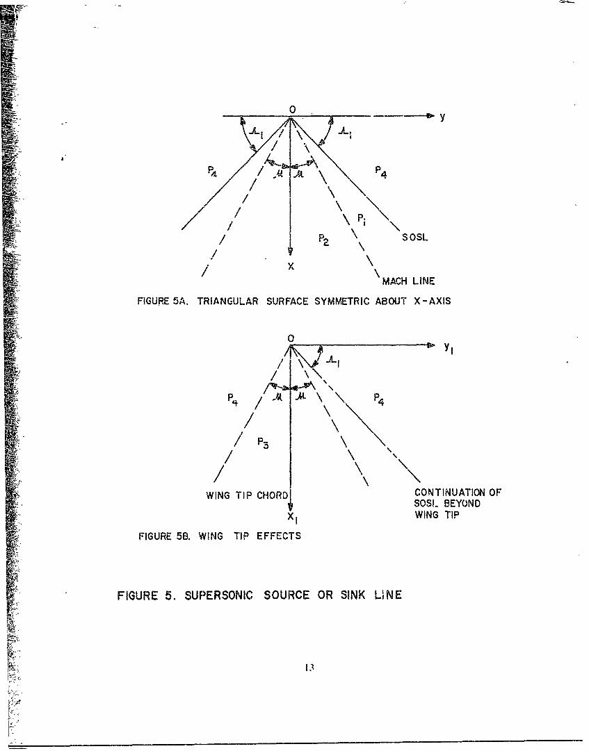
Ib. Supers nik SOSL
If the wing generator is supersonic. the Mach lines fron point Ii"in Figure SA lie behind the SOSL. If in Figure 5. P P-l)1, then the induked%elocity a! Pl Jue to the distiurlance caused by the SOSL is- 13
-. 5\ --, - (101
It' P) P,. the .nduced velocity is
Referrirg to Figure 513. the additional induced velocity inside Ilit, area boinded bh-L the tip mid the Machl line ennaniating from the tip (P 13 ) is:
\7N( \ r 3 ' . ) I 2 1p I"- J-Z2os '(12)
•x/T-7r L~ltIi +1O0.
""1+
0
1'/ \P. \P•S•PSOSL
x/ "\MACH LINE
FIGURE 5A. TRIANGULAR SURFACE SYMMETRIC ABOUT X-AXIS
0
P•f //. t\\
/ P3
i• ~/\
WING TIP CHORD CONTINUATION OFSOSL BEYOND
'X IW IN G T IP
FIGURE 5B. WING TIP EFFECTS
FIGURE 5. SUPERSONIC SOURCE OR SINK LINE
13

Again if P = P4 " the point is out of the zone of influence of tile SOSL and thusthe induced velocity is zero.
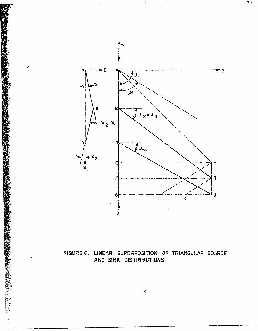
'rThe induced velocity at a given point on any whig geometry cannow be computed by the proper superposition of tile triangular SOSL bhown inlFigures 4 mind 5. Thib is because of the l,,,ar nature of' the governing flow-field
Equation (i ). As an example of how the above superposition principle works,consider tile wing shown in Figure 6. For simplitity. the slopes X, and X2 areconstant. The ving AHJD c•n be represented by the sup.-rposition of five SOSL.The fiist has the planforin AEH and source intensity:
w(x Py ) V-X!
where X, is tl:e slope of the segment AB. Tile second has the phlnform BJI and"intensity
w(xy) l (x - x1 )V,
and the third the planform DJG and intensity
w(X1j.y) -Y(p~y) =-2V-
File other two SOSL represent the tip effects. They are the planforms IIJL and IJKand have source intensities of opposite signs than those representing the wing.
The above procedure can be applied to a wing of generalplanform. The only difference is that for each point in qý estion, the slope is notconstant as was the cj,e in the simplified example. Then for some general pointlocated on the win, surface, the total induced velocity due tL all sources and sinksim flbmd by applying one of the Equa tions (7) through (12) for each SOSL. Theparticular equation applied depends upooi the Itcation of the point relative to theSASL and the Mach line as discussed earlier. Tlhese individual c:ontributions are thensumninled to get the total induced velocity. Knowing the total induced velocity at apoint allows one to calculate the pressure coefficient at the given point by:
14
Mlo
A Z A
I N.-
BFX -. L 3 2 -&
D D
X/
GL K
P' X
FIGURE 6. LINEAR SUPERPOSITION OF TRIANGULAR SOURCEAND SINK DISTRIBUTIONS.
c P lx~y) =-2o(jxmy~O) (13)
The pressure coefficient, can b, calculated at a given niumber of' spanw it~ andchordwise locations. Thie drat: of a vivenl ai'ioil seC 'll M t(lie styalnwist. Stationi
Y y is thenl
AA
Cd C(Y~ k . Cl,(\.YX )W('ý-'A )(lX (14)
The total dIrag. for one ýiti of senlispan h/2 is theni:
CD { C(ct)dy (15)
Where Sit b/2(cr + e1) For cruciform fins. thle total drag coefficient is:
If it is desired to base the drag coefficient onl the body cross-sectional area, thlelFiuation (1 6) mi'st be multiplied by tihe Iaietor SW/ le
['quations (14) aiid] (10) call be integrated by numericalquadraiture it' the generators of' thle wing, airface are super-sonic. If the gwenerators aiesubsonic, linear theory indlicates the pressutre coefficienits go to infinity at thle winggenerators. Physically. this cannot lie true which mecans that for subsonic SOSLlInear theory is not valid at thie SOSL. The reason is that the veocity pert t -itbt ioiiinl thle Vicinity of tile discontinluities are no lon~ger small, violating one of' thleassumptions in) linear theory. However, thle Velocity perturbations ire smlall a sli~ghtdistance from the SOSL so that linear theorý canl be applied. Numerical expcrimen tsnidicated at distance of liv! thou-sandthis of thle chord length from the SOSL was
sutfficient 'ind the 'value of pressur& cak~ulitd At this point was assumied to c\ist uplto thle SOSL.
[hle previous" allalys:j ple to airf'oils with sharp leading and'railing edgevs If the airfoil leading or trailinlg edge is blunt, some other methodinwut be applied in the O cinit\ of'tlt 0u ii a ted portionl bei ause the asumilptions o

perturbation theory are violated therc. In analogy to the work of Refert flce I,modified Newtonian Theory will be applied to thle blunit leading edges and anempirical afterbody separatibn pressure corrtctioni applied at the blunt trailing edges zs willb, discussed iater.
The modificed Newtonian pressure coefficient is
cp= ce, S412 0 (17)
where 0 is the angle between a tangent to thc local body surface and theireestreami direction and %liere the stagnation pres-sure Loefficient behind a normalshock is:
_ _ _ _ _ _
If the blunt leading edge of the wing is cylindrical in a oircction perpenidicular tothe leading edge. then this circular shape appears as an ellipse in the streamwisedirection for sweptback wings. Thus, for ,, given point onl thle airfoil leading edgewith coordinates (x,y.z), it can be shown that t~eAppendix A):
Oe"'.Y,') =tall {oA, [FL (y) x cos A} (19)
Note that [~quation ( 19) assumes tile leading edge radim, miay v~airy along thespan, that is r, , (y). Th pressure coelficient ovor thle elliptical leading edgecanl now he calculated AI~ each airfoil section by com-bining Equations (1 7, (1, 8),and ( 19).
The quesdicn that remamns is whecre does one start theperturbation theory aft of' thie blunt leading ed~e and where does one enld thlenmodified Newtoniati Theory. Before proceeding to inswer this question, it is helpfulto review the work of ROlcrence 1 , which c'ombined the seioncl order p~erturbationtheory of Van D~yke with thic modified Newtonian Theory to calculate wave drag onlbmiui bodies of revolution. In that work, the perturbation theory was started as farupstream onl the sp~herical cap as p)ossib~le while still getting reasonably accurate
petraio pressure cj~efficients, It was folitid that slopes of' 25-30 degrees were

optimum. Althougji the results were unpublished, it was found in that woik tPlat iffirst-order perturbation theory were used, this angle must be reduced ýto abogt 15degrees. Also, it was found that second-order theory accounted very well i r theover-expansion region around the spherical cap whereas the first-order theory dii,not. The important analogy to be drawn from this discussion is that for tl,,cedimensional wings, a first-order (rather than a second-order) theory is combinedwith modified Newtonian Theory to calculate wave drag when the leading edge isblunt. Thus, in analogy to bodies of revolution, one would intuitively expect the"angle where perturbation theory begins to be around 15. A discontinuity inpressure coefficients of Newtonian and perturbation theory is expected at the matchpoint due to the failure of the first-order theory to account for the over-expansionregion.
Figure 7 compares, qualitatively, the first and hecond- ordertheories when combined with modified Newtonian Theory. The second-order theoryis started at say 0, = 300 and the flow allowed to overexpand around the shoulderand recompress downstream. The pressure coefficient will usully intrsect that ofNewtonian Theory and this is the match point, x2. indicated on the figure. Thiscombined theory usually follows the experimental data reasonably well. Thefirst-order theory starts at 01 = 15' and the pressure coefficient (toes not usuallydecrease enouglh to intersect the Newtonian theory. hlence, a discontinuity in thepressure coefficient curve for the entire configuration exists at the match point, x,,For drag calculations, the Newtonian Theory is used up to the point x, tVlichusually will be at the juncture of the cylindrical leading edge and the airfoil a-fter-body) and perturbation theory past x1 . The drag coefficieit of the blunt leadingedge is (see Appendix B):
CA 1, R,,vS bC,, cos (si si3 01
vwhere(r, - + (rLI.)t
Ravg 2
The drag of the section aft of the cylindrical leading edge canl be found bynumerical quadrature of Equations (14) and (16).
~18

c P
0 EXPERIMENT (Moo<Z)
Ist ORDER PERTURBATION
0) ýn ýd, ORE PERTURBATIONif: I ( ... _. _ _ N E W T O N IA N
5 ----i'i
LE
xx2 xi
FIGURE 7. COMBINED NEWTONIAN AND PERTURBATION THEORYFOR A BLUNT LEADING EDGE.
19

2. Skin-Friction Drag
In general, the boundary layer consists of a laminar, transitional, andturbulent region; however, no apprecieble errors in total drag will be realized byassuming a laminar and turbulent region with transition taking pla•,c inbtanteously.Moreover, transition from laminar to turbulent flow is assumed to occur at aReynolds number of 500,000 based on the wing mean aerodynamic chord.
According to Van Driest, the skin-friction drag coefficient for a singlewing is then:
CA f ICfT)',+ Cr - (CfT) (21)f I " Sref
I lere (Cc )- and (CfT).- are the mean skin-friction coefficients ol turbulent flowbased on the mean chord and transitional location on the mean chor(., respectively.They are computed by solving:
A C )"/'(T wl )04(sin- 13 B +sin-i B2) log (RN Cr (r - log, 0 (2 )(2
implicitly for C,. where q for air is 0.76. The Lonstants A, B3, and B1 ofEquation (22) are defined by:
2A2 - F F13 -1 .2 + 4A 2)"/ 1 12 (1 -2 + 4A 2)' -
A -IL -)M ,I2. . 1 = , 1 - I )/2M :
iYi L I)2 Tw/T_] TNI,. -I
The Reynolds Number of Equation (22) is
V,RN (• 23
2()
4i

where 2 is either ý or R. The wall tuniperature can be related to tile freestreamtemperature byl
[f. T = I +0.9 -- M2 (24)
Finailly, the laminar skin-friction coefficient Ct, isq
1.328 (25)(C] •
where the Reynolds number is based on 7.
3. rrailing Edge Separation Drag
If the trailing edge is blunt or if its slope is large, the b1oundar, layerwill separate somewhere on the rear of the wing. This results in a high drag regionsimilar to that on the base of a projectile, except here tile separation iS atwo-dimensional as opposed to a tl,r.-tdiiensionl phenomenon. The pressure on therear of the wing will then be that of a two-dimensional rearward facing step.,(hapnian1 Is) presents experimental results for a blunt wing with no slops, at tiletrailing edge. These results are presented in Figure 8 as a function of Malh number.Note that thl- data for M, < LI has been extrapolated based on the general shapeof' the three-dimensional base pressure curve presented in Reference I. If (rl, )F andh( I Ij) are the radius of the trailing edge hqlpitn,'ss at the root and tip. respectively.the trailing edge separation drag for one fin is (see Appendix C):
td( r. )r 1,), I. W
CA 2srel ]" (2o)
I oi cruciform fins this becomesv
"I( S rTI )r + (r, t27)
21

.5- EXPERIMENT (REF. 15)
EXTRAPOLATED(BASED ON 3-D CURVE)
i - CP8
0 0
F R 8
/MFI UR . - B SE P ES U E OE FCI N
!!•. -/
i-c
B = • .

4. Base Pressure Drag Increase Due to Presence of Fins
There are several primary lactors which determine tile effect or 1insoil base pressure. Thest. factors are fin location, thickness ratio, aspect ratio. profile.sweepback anglk, and number of fins. Based on the siall amount of experimenitaldata available, it is not possible to accurately account for ani of the above factorsfor a general configuration. However, order of magnitude effects (A, two of the%,ariables, fin location and thickness ratio, can be estimated using References 16through 19.
To estimate the effect of fin thickness to chord ratio on basepressure, it will be assumed the fins are flush with the base. The effect of the finsnot being flush with the base will be accounted for shortly. Figure 9 is a plot ofSACpB/(t/c) versus Mach number. Here
AC 1,1 = (CPB )With fin h- (el'V )n o fin s
The points above M. = 1.5 were taken from the data of References 16 and 17whereas those points below M_ = 1.5 were taken from Reference 19. Again itshould be emphasized that there are too few data points to put a gfea (eal ofconfidence in this curve. For a given Mach number. M1 , the increment ia basepressure due to the presence of fins is then:
(ACi')cV (27)
Tile values of t/c which (27) was derived for were ten percent or les".
The work of Spahr and D)ickey17 hjas shown that if the finswere placed upstih-im a given distance rather than flush with "he base, the effect onbase pressule is not as great. Furthermore, if tile fins wer1 mo Cd far enough from
the base, they would have no effect oil base pressure, the amount of this movementbeing dependent mainly or, fin thickness to chord ratio and profile. As seen inFigure 10, this distance varies linearly with t/c ulp to values of 0.10. The curve inthe figure is then extrapolated from tic = 0.1 to tie 0,.2
23

z co C,,tzi
~wLL:LL 0Sw w iL/
AP z
~8 w
W~ z
cD
H
00 N-
CD)
'N

/
//
/ S1.2- /11 .! / -0 ExP. (REF. 17
..... EXTRAPOLATED
XTE
XTE z DISTANCE FROM BASE TO TAILTRAILING EDGE WHERE A RN OF"GIVEN THICKNESS HAS NO AFFECT
4 ON BASE PRESSURE.
0' '- I ! ! i
0 0.4 0,8 .12 ,16 .20t/c
FIGURE 10. DISTANCE FROM BASE WHERE FINS DO NOT AFFECTBASE PRESSURE.
25

Now if a linear variation of (AC1 B t is assumed between its maximumwhen the fins are flush with the base and zero when the fins are far enough awayfrom the base, then Equation (27) may be modified in the form:
[ACrB (t . >0.1
, cLB =- - 0( j c) C (28)
(AceIt)f = 0 1t < 0.ixC c
X/C in Equation (28) is the distance (Gi chord lengths) upstream of the base. Thisempirical relation was derived only for cruci'ornh fins.
C Tail or Canard Alone Lift
To calculate the normal force, the wing is assumed to be represented by aflat plate of given planforin with zero thickness and camber, This assumpti, m isjustified because thickness has only a second-order effct on lift (except for thickwings in transonic flow) and most missik configuration, have wings with zerochamber. Thie melhods used to compute the cmnard or tail alone lift are differentfor subsonic, supersonic, and tran-onic flow and will be discussed separately below.
1. Subsonic Flow
'IlThe basic equation of motion is Equation (1) with boundaryconditions (3) and (4). The ooundary condition (3), under tile assumption of zerothickness and chamber. mam be nimplified to-
w(xy) -• y (29)
In addition to these boundary cnditions, the Kutta condition (which requires thevelocity on the upper and lower surfaces at the trailing edge to be equal) is alsoimposed for subsonic flow. Equation (I) may be simplified somewhat by using(;othert's rule' 20) to relate thit' compressible subsonic normal force om pitchingmoment to the incompressible case. That is:

-(- M(. (30)
•(C,.)I.N I ,:.• )M = .,(31)
"However, it was assumed apriori that tile only contribution to lift was due toangle-of-attack, so Equations (30) and (31) may be simplified to:
S~(CN )o,o,• ,,•"(CN- )(C* .,,0 At0 (32)
I - M
(CM )MoN .•A.ct = OOk0 (33)1 - M2
The way this rule is applied is as follows: given a wing of aspect ratio, M.,freestream Mach number, M-, and angle-of-attack, o:, the normal force and pitchingmoment can be obtained by calcu!ating the normal force and pitching moment onanother wing of aspect ratio PAR, Mach number zero, and angle-of-attack 60Z. Usingthe above relations, the normal force and pitching moment on a given wing at anysubsonic Mach number may be found by ,alculating the aerodynamics of an affinelyrelated wing at zero Mach number.
For M. = 0, Equation (I) reduces to La Places Equation:
S.y +4ZZ =0 (34)
The solution to Equation (34) can be shown to be:(21)
O(xyz) = -- AC"(x-Iy 12 j +yy )"2 +dxdy 1 (35)
s
•27

3-
where AC = CP- CP. It is riquired to determine the pressure loading ACp overthe entire surface. Following Chadwick t2 2 '•. Equation (35) is first differented withrespect to and tile limit as ., -, 0 taken. The result is then equated to theboundary condition, Equation (29). to obtain:
S+ f-J)2 dx1 dy, (36)(y= L -X
rie cross on the y, integral indicates a singularitv at y yl, in which caseManglers principal-value technique(2I) L.an be applied. The details of the solution ofthe integral Equation (36) for AC1,(x.y) will not be repeated here as they are givenin detail in many references (see for example, Reference 22). Worthy of note.however, is the fact that EFquation (36) is an integral equation for which tile wingloading ACp is to be found as a liiear function of angle of atiack.
Once the span loading ACp(x,y) is known over the entire wingsurface. the normal fore. at a given spanwise location is:
C, I I= -- ACPdx (37)Sc "'l. F
Tile total normal force for the entire wing is:
b!22f
NC =- cCcdy •78)
The pitching moment of a given airfoil wection. about tile point whwrethe wing, leading edge intersects the body, is then (positive leading edge up):
CT EC xAC dx (39)""ref f-
28

The total pitching moment becomes.
2 bi2 -
- cCm dy (40), Ser
If it is desired to calculate the pitching moment iibout some other reference point,then
C0 =C + ICN X041IM I N rcr
where x0 is the distance from the reference point to the juncture of the wingleading edge with the body. The center of pressu:re of an airfoil section is:
x U- (42)
or of the entire wing
x C% (43)• C I'= C N
Finally, the spanwise center of pressure of a wing selnispan is:
b142j cCn ydy
f cC 11dy• ()
Equations (37), (38). (39)L (40), and (44) can be solved by numerical quadraturt. such awSimpson's rule, with special attentio!- given to the leading edge singularity
Y
i'

2 Supersonic Flow
Hfere again Ftluation HI) is valid along with the boundary conditions-;(4) and (29). However, it will be assumed inl the present wvork that the wing,
trailing edge is supersonic (Mach number normal t(, wing trailing edge is greater thanone) so that tile Kutta condition need not be applied. Two cases will beconsidered: supersonic Ileading edges and subsionic leading ciges. For both cases theflowv is conical inl nature from the vertex point which is the intersection of' thlewing leading. edge wvith the body.,
a. Supersonic Leading Edge
Since the flow~ is conical, the lo-w properties ire conlstat-t alongray,; emanating from the vertex point and lying behind the Maclh ine. Refcrring toFigure I I A, where thle leading edge Mach line intersects the wing trailing edge, thismecans that if thle flow properzies it one point onl the ray are known thyareknown all along thle ['Iy. It is then a matter of' computing the hiduo-d velocitiesand hence lifting, presIiurcs onl sc~erzii rays from point 0. Thle lifting pressure onl anyonle ot thlese rays inl Vegionl 2 IS. 13)
wvhere q? and ai were define~d by 7 A Ahead of the Mach line, inl relgion 1 , the flowis two-dimensional so the lifting pressure is constant at:
4aAC, ACP -12 4o
If' the win,~ we!re tapered to a poin t, the ,above two relationship.;would allow, complete determiniiatioil of' tile lf*ting pressýures over the witig. For mostpractical cases, the wing, tip is not poinlted -,( tip effects must be: accomnted For.'[he tip) affects thle pr"Sure Within the Mlachl line from thle tip lead ilig edgOregion 3). Within III,, r,ýgiohi thle flow is, again Conical alonge rays troll) poin)it I) so
tile li1111 ow prCs.ujrC ci I~ y thle ip) i,,,(23
'o

0 y
AREGION AREA.,I OAFD
2 AG2 ID 3 DEF
/G
A 3A F E
S~xCONICAL RAYS CONICAL RAYSFROM 0 FROM D
REGION AREA':•,,•, •i OHD
"2 OHFG3 DEAH
D 4 AHF
• G
!•x 4
FIGURE IIA. FLAT PLATE WING PLANFORM WITH SUPERSONICLEADING AND TRAILING EDGES; MACH LINE
INTERSECTS WING TRAILING EDGE.
31

'lt-~ ori-ginad equation of m1otio~n, Equation (1), is linlear so that superpositionm of"~Outmons is allowed. Thus,.1he total lifting pressure in region 3 is:
AC1, =Acp I + act)
If the situation arises such that the Mach lines inters~ect. as shown at the bottom ofF'igure 11 A. then anl additional pressure of AC1, is created] in region 4. Hence. thetotld lifting pressore in regionl 4 is
AC,, AC1,) + ACP2 3
lMe second case to consider when the li~ading edge is supersonicWhen the leading edge Mach line intersects the tip) as llustrated "n Figure I I B.
fl~c lilting pressures inl rtgions 1, 2, 3, and 4 are calculated inl tfl sano! manner aswhoji thle Maclh linc intersects the trailing edge. Hlowever, in region 5 the lift to becancelled along the tip) is variable (see FPuation 45) as opposco to the constantvalue cancelled in regionN 3) and 4 (see Equation 40). [his compl~icates thie problemýowo'what in that a su mmat(ion (or integration) must now be p)erformled to calculate
dile w1nceMllalj lilt inl region S5. Ref'rring to Figuire 1113. the region 5 is brokendowAII into a limte wimber of intervals, in the following manner. (Conical rays froimOwa vertex at 0I are projected behind thie M'vach line OA and intersect (hie wing,, tip) atequali inltervals alo'ng (hie tip (For example, rays Qi and OK). Lines are (lien drawnhll) the pioints- of intiersoction on the wing tip) %trallel to (lie Mach line Al until11'v poinkt P( N,V ) is enclosed. Thle difference inl AC, across one of' these intervals iswitat imust hký caucelled throughout thle regio.n S. For any gixen interval tMen, saý1K rums dlffcrenme in pressuie is found by applying t'qtatioii (45) to eadh of' thehi S trom 0 passing throuigh J and K. That is-
AC, (\1b,1)A! vb2 ACp (X~h,2)
32

"0 E
> A
* INTERVAL JK
'E
"y-b/2
REGION AREA Cip" tan.• X-X
I OCH x"2 OHFG3 AHD4 FHA 15 AEI
FIGURE 1iB. FLAT PLATE WING PLANFORM WITH SUPERSONICLEADING AND TRAILING EDGES; MACH LINE"INTERSECTS WING TIP.
.. y, 33;

!FACP (x.b12) - - - sill_
K1 - (-2
Tihe effect of this cancellation pressure at any point PeX.y) is then:
4KC, (x,) ACP (x,bj2)- tan +(48J P J K 7.r - jp(l + 77
Now the interval JK is any interval upstream of the Mach line from P passing'Iough tile wing tip. If II is the total number of intervals upstream of' P. then thetotal lifting pressure coefficienlt at point P(x.,y) within region 5 is:
I-' Inl
ACP= CI + zWP + 2:1~1- 1I
vwhere AC is given at each interval b. Equation 148).iPi"
The lorce and moment coefficients can now be found bysubstituting the expressions for ACp in each region into the Equations (37) through(44) and performing the indic'ated operations. The integrations could be carried outin closed form for regions I through 4. but the formulas are very lengthy for eventhe inmpliest cases.,'2'" A more straightlorward approach is to simply numericallymtegrate the ilitegrals over the entire surfact . particularly since the pressures inrevion 5 ha'e to be numerically integrated.
b. Subsonic Leading Edge
For subsonic leading edges. the velocify and lifting pressuresapproach intinite values near the leading edge. The solution fbr AC,, is complicated
4> ,,,,mewhat by flus singularity, but due to the conical nature of Ihe flow from theicrt,.x points 0 and 1) (Figure 12), a closed form solutfion can be obtained, Formrehim I of Figure 12 this is:(21)
,: 34

0 _ _ _ _ _ _ _Y__ _ _ _
NLE
i """
x H
REGION AREA
• I ODFG ";F2 DFH
S~FIGURE 12. FLA'F PLATE WING PLANFORM WITH SUBSONIC
LEADING EDGE AND SUPERSONIC TRAILING EDGE.
3
?:Ng*L ;.. .. .. .. .. .. . . .. . . ...N

4cp= ACp ta (49)A~t'= "XI" =E tan A, viVi - oo
Swhere E is a constant dependent only on the leading edge sweep angle and Machm mnber.
That is,
E(k = I - k2 sin- OdO (50)
'1i1d k = %/ - AL, The value of the complete elliptic integral E(k) hasbeen tabulated and appears in standard mathematical handbooks.
'iThe lift to be cancelled at the tip is variable as was the case for"supersonic leading edges when the Mach line intersected the tip, However, in thiscas,. the integration can be carried out in closed form. Thus, the cancellation liftingpr.ssure is: 2 3
4c [ F2(b/2-y)P.AC P, = 312E (=') - ,K(kj x+j y (52)
-2 71x252y2 K(k') - K(k)E(k' + K(kFlk',.ý
-2x 2L2)[
: = ie k (1-- a0 1)(?- I ) k' %I i
i (x + j3yrt) Pb/2'' siWn-I (3b12(I ++i~ x 03(y - b/2)
36

Here F(01 .02 ) and E(O,1 02 ) are elliptic integrals of the first and second kind,respectively, which again can be found in any standard mathematical handbook. Thecomplete elliptic integral K is related to F(,O .02) by K = F(01 ,r/2) and thecomplete elliptic integial E of Equation (50) is related to E(0 1 02) by"E = E(0 ,7r/2).
The total lifting pressure coefficient at any point within region 2is then
AC, = ACp + AC
The integrations for spanwise lift and pitching moment can beobtained by integrating Equations (37) and (39) numerically. Howev.r, caution mustbe taken in these integrations because for subsonic leading edges, the lifting pressuregoes like IAl//"" near the leading edge. In this vicinity, more mesh points must beadded to the flow field to get an accurate ir tegration.
'Fihe total wing normal force and pitching moment can be easilyobtained by numerical integration of Equations (38) and (40). The cho.1'dwise centerof pressure is then found from Equation (43) and the spanwise center of pressurefrom Equation (44).
3. Transonic Flow
As mentioned earlier, airfoil thickness has a second order 'ffect onlift ill subsonic and supersonic flow. However, this is not true in transonic flow sothe assunmption of a flat plate with zero thickness is no longer valid except 'or verythin wings. Furthermore, as M. approaches unity, Equation (1) cannot be appliedbecause the term (1 M2,)-1 )0 becomes of the same order as nonlinear terms whichhave been neglected in deriving this equation from small perturbation theory.
Recent progress in the field of transoni, aerodynamics has greatlyadvanced the state-of-the-art. However, at present, practical methods for flow fieldcomputation are still seveo'ly limited. For example, solutions for three-dimensionalswept and tapered wings with thickness do not exist, even in approximnate form. Inlight of these considerations, an empirical approach to wing lift in transonic flowwill be used. The metliod adopted is that presented in DATCOM.( 24 ) This procedureaccounts, in an empirical manner, for sweep, Mach number, aspect ratio, andthickness ratio but not lbr airfoil section.
F

To apply the above empirical procedure, the force break Mach numberfia foundd from Figure i3A tor a wing of zero sweep and corrected for sweep by
Figare 13B. Tlhe lift curve slope at the force break Mach number is then computedby a simple expression derived from lifting line theorv:(25)
} (C 27 = 2(59)
CN fb 2+ I R 2 (g 2 + tan 2 A,/) + 41 (
This value is corrected to agree with experiment according to Figure 14A. Theabrupt decrease in lift curve slope associated with thick wings is approximated bythe relation:
( CN (I -' a/c)(CNQ)fb (60)
where a/c is given in Figure 14B. The Mach mmber at point a is:
M = +0.07 (60A)
The subsequent rise in CN, to a value at point b is
"(CN = b/c)(CN )f) (61)
where b/c is given in Figure 14C. The Mach number at point b is
Mb = Mfb +0.14 (61A)
'rie normal force curve slope at M > 1.2 is calculated by supersonic thin Wingtheory and for M < Mfb by lifting surface theory. F'rom this empirical correlationone obtains (CN t.b, (CNO), (CNO)I at the Mach numbers MfbW Mfb +.07, and.MIb + .14. For values of CNO in transonic flow in between these Mach numbers,interpolation is used.
38

(Mfb
0 4 8 12 16
THICKNESS RATIO (% CHORD)
FIGURE 13A. FORCE-BREAK MACH NUMBER FOR ZERO SWEEP
1.09
(MMfb)Af=0
0 20 40 60 80 100AL (DEG)
FIGURE 138. SWEEP CORRECTION FOR FORCE-BREAK MACH NUMBER
FIGURE 13. TRANSONIC FORCE-BREAK MACH NUMBER
39C

i- R 6\B,"
80 4 8 12 16
THICKNESS RATIO (% CHORD)
FIGURE 14A. CORRECTION TO LIFT-CURVE SLOPE AT FORCE-BREAK MACHNUMBER
.8 -8-- -- -
.6 - - 4
c 4- -
-.2 i
0 4 8 12 16THICKNESS RATIO (% CHORD)
FIGURE 14B. CHART FOR DETERMINING LIFT- CURVE SLOPE AT Ma
.2
b
0 T T ]
0 4 8 12 16THICKNESS RATIO (%CHORD)
FIGURE 14C. CHART FOR DETERMINING LIFT-CURVE SLOPE AT Mb
FIGURE 14. CHART FOR DETERMINING TRANSONIC LIFT-CURVESLOPE AT Ma AND Mb
.4or _______ ____

The center of pressure of wing alone lift is usually around the quarterchord for subsonic flow and half chord for supersonic flow. Transition fromsubsonic to supersonic flow is assumed to occur in a linear fashion between valuescalculated at MN1 slightly less than M fb and M. > 1.2. The pitching momentcoefficient derivative of the wing alone is then:
X CN (62)
D. Interference Lift
Interference lift is broken down into three parts: lift of canard or taildue to presence of body. lift of body due to presence of wing or canard, andvortex lift on tail due to wing shed or body shed vortices. The methods used tocalculate the interference lift components are essentihlly those presented inReference 26. Tile necessary eqluations for the various calculations will be repeatedherein, but for the details of the derivations, the reader is referred to the abovereference.
The method used by Morikawa(27) for presenting lift interfer,.ence isSadopted. He defines the wing alone as the exposed half wings joined together. Thelift of the combination is related to the lift of the wing alone by the lactor K( sothat
LC, = Kc Lw (63)
Kc is aclually composed of three components,
=X B(w) K ( 1 ) 11 (64)
which are the ratios of the body lift in presence of the wing, wing lif in presenceof body, and body lift to the lift of the wing alone. That is:
41

KBiw) L- (65A)
LwKB) (65B)Kw(B) = L
t = __ (65C)Lw
We will not be concerned with K1B as it was found in Refcrence i as discussedearlier. The factors K(,) and K ,(B) are found from a straightforward applicationof slender body tneory and are:
(K- r2/s 2 )- 2/r (1 +r4/s 4)[½tan-' IA(s/r- r/s)+ 7r/41K1(w) =(1 - r/s32
r2/s2 [(s/r--r/s) + 2 tan- (r/s)I (66)
(0 - r/s)2
2/7r 0(I + r4I/s4 )[ V2 tan 1/2(/r - r/s ) + 7r/41W(OO- r/s) 2
(67)
r2•/s 2[(s/r- r/s)+ 2 tan-I (r/s)}(i- r/s) 2
K KWB) and KP(W) of Equations (66) and (67) are related to each other by:
KW(00 + KB(w) (1 +r/s) 2 (68)
42

Values of these parameters are plotted in Figure 15. Equation (66) is used to
calculat- KB(w) for all subsonic Mach numbers and for supersonic Mach numbers if
:3AR(i + X) l/mi) + I 1< 4. If A/R(I + )[l/(ml)+ 11 > 4, Nielsen( 2 8 ) has shown
that for no afterbody (set.; Figure 10), a more appropriate value of KB(w) can be
found from:
_ _ I•I m__K B w [ (C ) (X + l)(s/r - 17 8 "/-gd\2 +1I C
Cos- III +2 Cos-I +mCr/dj -mL 1 (d
+ ,11 t'0, Vm2i,- l sill V12_27 cos -1t (69A)
whell pim > I and cr/ 3 > d. If Plm < I and c1h)' > d, KB(w) is lound from:
16%fi'r (_d i
K , I (CN, +,II(X s/r" 1)= + ON /r (9r32l1 +
(69 B)
- (111)32 + 111 k'Pim + I ta n' - ta n~(~- I ==n.
If c1/P < d in Equations (69A) or (69B), c[/p is set equal to d. For an infinite
afterbody behind the wing or canard (see Figur, 16), Equatioms (69A) and (69B)
are replaced by:
43

[2.0 -- ____
1.6
1.48
1.2
1.0 BW
0.8 _ __(B)___
0.4
0.2
0.0 0.2 0.4 0.6 0.8 1.0r/s
FIGURE 15. SLENDER BODY INTERFERENCE LIFT FACTORS
44
"r- ,

xAFT
SHORT AFTERBODY
REGION OF INFLUENCEOF WING ON BIOCY -
INFINITE AFTERBODY (XAFT=d COT M)
MAC Hi LINE-\
K-Cr~NO AFTERBODY ( XAFT= O)
FIGURE 16. DETERMINATION OF K B~w) FOR HIGH-ASPECT-RATIO
RANGE AT SUPERSONIC SPEEDS.

K( 2 *-(CN,)wm (sira- 00 + X) -+13uni -W) jýd).~ ~
A• (1 + l/Gi)•3d/cr] co- [/ .... .: i2 /+
gil Cs (70A)
L +f m +(1 3m )J lde
for r13 > I and by
(C +0'( r + 11010)1jf- 1
KB(%v)[u(~W(~ 1)( N? 0 +~ C~3; 7/ od I+4n }
,+(I + l lnt3) - 2 I + I/(n63))L- i (70B1)i" e r an + I + ultnlo~dfcr
for 1111 < I Fmr cases in between no afterbody and an infinite aferbody, K I,•ay be
found approximately by linearly int-rpoating between the values given by Equations ((0)
and (70). That is, refetring to Figure 16,
[K (KB(w]IA - [K NAw)] Ni (71)
1B(w I S d cotI pA FT N rA
Here the subscripts SA, IA, and NA refer to short, infinite, and no afterbody.
r'spectively.
In addition to the normal force due to angle ol attack, there is a
normal force created due to wing deflection 5. The lift of a wing due to a
dellection 6 is given by:
46

r ,win) = kwil)(CNO a (72)
(2 " I, r+16 + wl ('/r) 2 + 2 i/0 2tr [(s0 2 -
I(, , 2 + +n
li'r +r) 4% to %/)
""ri '. / !r - %/r)P04/r -)5•/rI L(0/r)2 + 1 J
If%,/r+_ II____1 8 r(L /r)2 + (73)+ - o/r1% 1011 L _ % /r)?r I+ ) L2q/ JI2r
liiv lift oti thc hody dile to the control deflection Is
)"N8,W) kA48lfrNOlwV (74)
KV 111) kwf N) (75)
k , and Kiti t are given in Figure 15 as a function of r!s.
Strctly speaking. Equations (66). (67). and (73) apply to slenderwin,,-I.od• ,'mrpti1r:Itions which have low aspect ratio wings. Furthermore, the
tr1.!inV ,,I,', of these wings must be perpendicualr to the body axis or swept
hfrrwaid i•|,t canrot be swept back. Neilsen (26 ) has shown that good results can be
,I'n,=in, lotr thi intcrfellnce lift components for high aspect ratio wings even
vio'nii tihe slcndkr body approximation is madc. However, if the wing trailing edgeis %wýwpt N:ick the previous slender body formulas are not applicable without ftirther%iild\,. For wings which have swept back trailing edges, and where slendqr bodytij,,rk, j, i.i,,'(I to calcuite interference lift, it seems reasonable to assume theinai,,,li,• t ot, the wing cuic to the presence of the body Is distributed evenly
limig the wing chord and is concentrated near the root. With this assumptior, the.,I, , il com11ponents or a swept back wing may be approximated by:
4Bost Av&Gae Copy

[K [K) Gic
Kw(b]~ 11 [i K~. 1 l)
;11 Os' 11 11, =(kw (B JI - [k. w{(B j)G
where G (Cr.)i/(Cr)1 and the subscript 11 refers to the actual wing beingtonsidered and subscript I refers to the wing for which the slender body Etquations(00). (67), and (73) assumes, Figure 17 indicates how the above procedure is carriedout.
The negative lift caused by downwash of the canard shed vortex on thetail is given by-:
(CN,•)w CN ,)j j1[Kw ,, ,sin o•+ k• ,(,,,in 81i~s - r)w Swi; C.. 2TrR.w.(lf - rw, )S~CN =,,S, (7o)
This e('1ation is determined from line-vortex theory assuffming only one trailingvortex per forward winp panel. The lateral location of the vortex, l , measuredfrom the body center line is:
fv (Cr (77)
-:ihe span loading at the root (Cn'cij •md normal for,.: coefficient are known for theparticular wing geemetry as dkisssed previously. The interference factor, i. of
uIIation (76) is.
4,

DESIRE: K(8jfK 13 w)]
W[kw {~k 8(w)]
orBODY SURFACE
FIGURE i7A. WING FOR WHICH INTERFERENCE LIFT IS DESIRED
KNOWN: fw(B) rB(w)]
/.. BODY SURFACE
FIGURE 178. ASSUMED SLENDER BODY REPRESENTATION
FIGURE 17. PROCEDURE USED TO CALCULATE INTERFERENCELIFT FOR WINGS WITH SWEPT BACK TRAIUNGEDGES WHEN SLENDER BOGY THEORY IS USED.
49

/r fr ; 1)b L6 +L , b
where
L r f ;)= {s- rX- - ?) 112 + (f-)2
rs-r +/ th ta
fir 2 hrf 2
r1 rfi f2 +h 2 hi = f2 +h12
lh = - 3 (c)\dW/4 sm 4 IQ.r+ - 3(crkw/4Isinox
Here it is assumed that the hinge line of the wing is at the quarter chord.
The only remaining lift is the negative lift on the tail due to the body.hed vortex. This is
-4r' +2j (CNII(V) -Tr + (79
LrI'Tl4I
5()

where
"P Kw a)c+k, 5- () U(3 (CN W SW.V 4(f,.- r,,
-• The center of pressure of the wing lift in presence of the body, canards;hed vortex lift, and body shed vortex lift are all assumed to act at th• center ofpressure of the wing alone. The center of pressure of the body lift caused by thewing is Mach number deper nt. Complicated expressions could be derived forcenter of pressure of this sift ,.omponent in supersonic speeds analogous toEquations (69) and (70). However, a good engineering approximation is to assumethat the center of pressure is at the tentroid of the cross-hatched area in Figure 16.This eliminates the need for consideiing separat--iy the afterbody, no afterbody, andshort afterbody cases. Thus, for supersonic flow, the center of pressure of the bodylift caused by the wings is (measured from the wing leading edge):
c~d[2- o22d3/6+ XFT(2d- xAFT/3)-,x3/2 (80A)Xep (cr - fld2/2 + xA T( 2 d - XA 0T/28)/2
where-d/2 - xA F Tr/(38) -
X3 cr + XAFT [d- r 1,/205~~
for
Od- XA FT > 0 and (Od - r xArFT) < O
If Od - xA :T >, 0 and (Pd - c xAlFT) > 0, then:
3 /2 (c, + x•. 1-) 3 -_c+ x 2_ r__(80)xCp (Cr+XA )2 X2 T (801)
51
rAP

lHicall, if i3d - x. < 0. then
x Cp +d (-801C
Fltloition (80A) reprewnts the case where the Mach line from tile trailing edgeintersect the base .,,ervas that from the leading edge intersects the opposite side.t-quation (80B) is used when both leading and trailing edge Mach lines from the%king root chord intersct the base whereas Equation (80C0 is used when both Machlines intersect the opposite side.
For subsonic and transonic flow. tl,,-re is much less tendency for the liftto be carried aft. For subsonic flow it i, reasonable to assume the body carry-overlift acts at the center of pressure of the wing alone lift. In transonic flow, the.enter of pres,ute is assumed to vary linearly between its value at the force breakMacl number and that computed for M = 1.2 by Fquation (80L
E. Summary Configuration
The total normal force of the entire configuration is:
+ [ + (K,(t + Kj, )) 'o + (kwV t + kj) 6] it (C )W
(It) + Kit (r)\ Cel (CN,,'Yr + CN I( + CN 1
DeImning
(CN -- [K w tq (B •)] (("N.)w
( = + e
52
SB(W) 9W + (cp )B(W)
2 T(B) QT + (Rcp)T
SB•B(T) * qw +(Rep)B(T)
the center of pressure referenced to the nose tip may be written as:
Q N w (B) + CN %(W)+ C N T(B) (82)
L = NB +CN (w(B) B(w) TB(B)
+ CN B(T)•B(T) + ( cN +CN R v)
The pitching moment about the ,nose is then:
CM = CN2 (83)
A summary of the various theoretical and empirical procedures used tocalculate the static aer"' -f the wing or tail alone and interference effectsis given in Figure t .ady indicated, a summary of the body aloneprocedures was given .. a..,re 2.
53

X 00
w ww(I) WOx
z 0 w 2
z< 0
L) w a
z -- L j -x 2
H- w w w 00 ) 0ZI-- -J-
0 0<<
Z 0
0 :3
m a0 C>- wO 0
uW 0DH U) w-
z (D 0
WO< W 0n
Co z 0 rMw Z w~j )zLLw w cr a. 0)z a>-
x. Z U. =U0U.. 0x1M
W Wz 00 w Ww
UL 0 z
w 0 W
z CD
0 w IrfO~00 E -w U))H oo I.
54

M11. RESULTS AND DISCUSSION
A. Comparison With Exact Linear Theory
1. Wing Wave Drag
For wing- which have simple planforms, exact linear ttheory solutionsexist b5 hiu%,h the present numerical solutions may be compared. Simple planflrmisare defined as wings with double wedge or biconvex airfoil sections with the sameairfoil s,.rlon and thitkness ratio all along the span. Simple planforms also halesharp leading and trailing edges.
Figure 19 compares the pressure coefficient of the present methodwith that of exact linear theory for a biconvex airfoil design.0 3) The pressureoetfficient has been divided by tic, the thickness to chord ratio, since it is constant
all along the span. As seen from the figure, the numerical solution gives essentiallyexact results when compared with the solution of Reference 13.
Section wave drag along the span of a wing with a double wedgeairfoil section is given in Figures 20 and 21. Figure 20 is for a wing tapered to apoint (no tip effects) and Figure 21 is for a wing with fifty percent taper. Theexact analytical solution is takL.n from Reference 31. Section wave drag at seventeenspanwise stations were computed but, as will be discussed later, only nine arenecessary fir reasonably accurate total wing drag. Again confidence in the numericalsolution is gained by the near perfect agreement with analythical solutions.
The final two figures comparing numerical drag calculations of simpleplanfornis with ;\act solutions give total wing wave drag for biconvex and doublewedge airfoil seciions. The analytical so'itions come directly from the chars ofReference 30 Figure 22 is for the double wedge airfoil wing and Figure 23 for thebiconvex airfoil section wing. Both wings have zero taper. Slight discrepancies of upto three to five percent between the ,umerical and analytical solutions exist atsome Mach numbers as seen from the figures. This is due to the numericalintegiation which smoothes out kinks in the pressure curves and due to truncation
7 errors. However, in light of the accuracy of the exact linear theory compared withexperiment, this discrepancy is quite acceptable for design.
All of the preceding cases were for sharp leading and trailing edge%imngs with simplc planforms. For more complicated configurations, closed formlinear theory solutions for drag have not been obtained. However, the presentmethod, which determincs the source strength locally can still be applied. For
55

3" ANALYTICAL SOLN. (REF. 31)
X NUMERICAL SOLN.
C/
'-I
)f/Cr =1.0
0.5
FIGURE 19. PRESSURE DISTRIBUTION ALONG THE SPAN OF
A SWEPTBACK WING WITH A SYMMETRICAL
CIRCULAR ARC AIRFOIL; JL=60'0 Moo=I.4tCt/Cr =.
56

2.0XT s-•b2
"Cr1.6 600
1.2"
Cd C
(tIC) 2 Cr.8"
4- ANALYTICAL SOLN.
X NUMERICAL SOLN.
0-.2 4 .61.0
FIGURE 20.SPANWISE WAVE DRAG DISTRIBUTION ON WING
WITH DOUBLE WEDGE AIRFOIL SECTION;P 6.92,Mc= 1.414,Ct/Cr =0
57

1.,S•°F• -• •-b/2-
Cr/2
Cr 00
1.6-
1.2-
CdC
(t/C)2 C r0.8-
-- ANALYTICAL SOLN.
X NUMERICAL SOLN.Q+
0.0.I0.2 04 0.,6 0.8 1.0
y / (b/2)
x04- X
-0.3
"FIGURE 21. SPANWISE WAVE DRAG DISTRIBUTION ON WING"WITH WEDGE AIRFOIL SECTION; P=3.26,Mao=i.414, C/C8r=0.5
58

9.0 ANALYTICAL SOLN.8.0 X NUMERICAL SOLN.
6.05. 0 _. _
4.0 C
3.c -
:: 2.¢ -
CDw
,1.0 . . . . . -
0.7---•0.8-
o.5;-•ziV..._-4-0.4.
Q2 x 2f•tanJ_
o,_____ _______•_ -.i-- J
00 10 20 30 4.0 5.0 6.0 70
FIGURE 22. WAVE DRAG OF WING WITH DOUBLE WEDGEAIRFOIL SECTION; Ct /Cr 1.0
59

10.09.C -1- ANALYTICAL SOLN.8.e - X NUMERICAL SOLN. -
7. -- ' -- __
Cr4.0 -
b
2.0 .
CDw
R (tic) 2
1.0 -
:•"0.8
Q7 ___0.6 ••t _0.5 _
0Q3 6 . .
i ' A3 ton -&
0.0 1.0 2.0 3.0 4.0 5.0 6.0 7.0
IR v M -I
FIGURE 23. WAVE DRAG OF WING WITH BICONVEX AIRFOILSECTION
60

example. Consider thle Winl" Jlowrn in Figure 24. t~his winl, Ilas ; variable Atrloisection and %ariahic tliickne'' all along, the span. Its design 1i, dictated by str''ictural.rather than aerodynamic. coiisideratioo~s. Also shown onl the figure is a plot ofpressure ,.ocIliciciit a.ilong the chord for itwo spanwise locations.
A secoud eurnfplo of' wings not co~'ered oN c~act linear tlieoi-\ is tli-winl,- with blunt lvadlin- and trailing xdges Figure 25 t-ves thc, total drag coefficienit(wine pluts inri*.tan plus trailing edtge separa'ionl for a biconvex airfoil with blunt
ldng, and traiiniig ed- ý and For three Mach numbers. Although no experimentaldat,! o\i,.t to compare tile theory with, the trends are generally Wvhat One WOUIIk
1),:t. Thar is bluint ness has a large ef fect on (Irag at high supersonic Machniumbers but at low stipersonic Machi numbers. the dlf'ect is not so large. However.
atthese low supersonic Machi numbers the linear tbeury results for very smallIlntniess ratios ate questionable. This is because inl the neighborhood of thle leadingedL'. where the slope is niear the ma ximuitm of' ififeen de-re\'s (linear theory starts atlslopes of fifteen deigree., where Newtonian theory ends). thle pressure coeftlciewnkpredlicitA l b linear thcorý ar'o quite large. dTe(iscont inuity between thle pre~ssit.cod l':Cient of Newtonian theory aind that of' perturbation theory is thus much larger.Hlowever. is the blunt ness ratio is increased the area over which linear theors% isaplilled decreases and hence on,., e\pects thle results to be somewhat better.
2. Wing Lift
T'hree cas-*ns are considered as test cames to com~pare tile nume11ricalSolutions with Closed forni mialytical solutions such a,; presen ted in Referen''es 32
and33.'fles inlud aWinio with subsonlic leaIding" and supersonic trailing edgeýs. awing wvit h st~personlic leading and trailing edges with the Mfacli line intersecting tiletip. andI a winge witil stipersi.)ic leading and trailing edges with the Macli lineintersecting the trailinig edge.. hiach of these cases is sufflicientfly different so as tocheck all met hodology dleveloped in the numerical calcidl~fion of lift onl winl(,, iiistuwersoiiic nohw. Thei theory, used in subsovic nlow has been p~reviously' verifiedI by('hadwick.1 221 Test (data niust suffice to determiine dhe correctness and accuracs oftile transonic tmet"odolog\'
20 Comipares tie wving o.ad ing along the spanl of a wing withsubsonlic leading anl] supersonic trailing edpes corresponding to thle [ir'st test caseabove, The Maich lines and regions where lineajr suiperposition of' solutions occur aremnd;..ated onl (lhe Ijeulre. As I% app~arent. tlie numneric'al solution is the same iN tilieanlylheal solttiofiou to (lie accuracy ,I olot ting thie data.
[guntes 27 and Di comparc the an~llatical and nmerlicaul \pl loadingcalc' ia tions for- a \kqpx'isomt. leading and t railing edge wiiig In Figure 27. (lie Machlinle just barelx hitcrsectk the tiaihing" cdlte where-as il figure 28 thle Mad) hine5of
Cp,
p-.10
, C RO, b/ 2 12.5%
0 -I0"8 .5
-. 100I
i•. .20 -
FIGURE 24. PRESSURE COEFFICIENT ON WING WITH MODIFIEDDOUBLE WEDGE AIRFOIL SECTION. Moo-2.0,bIl.02,!CR: .24', CR: .086', CR = .086', t' .0167', tt =.00421
SI 2
!i• 62

.25-
C- --7-!/
,•--: CDo .5
.1(> -" -- m oo =3.0--- * - 2.0
1.05
Q5-
O ' p ' I
0 0.2 0.4 0.6 0.8 1.0L r2 rLE/t
BICONVEX AIRFOIL SECTION
FIGURE 25. ZERO LIFT DRAG OF WINGS AS A FUNCTIONOF LEADING EDGE BLUNTNESS; Af=2,A 1 . L 4 =300, tic =0.12.
63

is CO
0
CC,
I00
a-
CL
zz
coo
9 M C
~1j 64

00
0 l u11
cr- -a
x (9)
CD
z
0L1
>-CC WIw cli 0
X.~ _ U)
z D X _
C9t
00
65

""-.I. z
CM
w
w
0
w
<..Sz Lz
0<0
_ 0 0
0
iCLVw
66
S.. . . . . L • • ..- . '.. . .. _ '. . .. .. ..... ..... ....

intersects tile tip. In both cases. the analytical solution is reproduced by thenumerical procedure.
B. Comparison With Experiment
Several example cases are ,:hosen to compare with experimental dataso as to place some degree of accuracy on the theory. The first of these is a tencaliber missile with clipped delta tail fins. The experimental cata are taken fromReference 34. which) gives the static aerodynamics for 0.8 < MI < 1.3. Figure 29compares theoretical drag coefficient, normal force coefficient derivative, and centerof pre,,sure with the experiment as a function of Mach number and for a = 1.Recall that for M_ > 1.2. the lift and drag (except for base drag) was calculatednumerically whereas for 0.8 < M_ < 1.2, the theory consists of mos1l• empiricalprocedures. For M_ < 0.8, the wing lift is calculated analytically but most otherforce components are computed empirically. With the exception of the noillial forcecoefficient slope at M_, = 0.8 and 0.85, the theory is well within ten percent orexperiment. The maximum error in center of pressure for this configuration is fivepercent of the length or half a caliber.
The next case considered is again taken from Reference 34 where thesame body geometry was tested with several different fins present. The caseconsidered is for aspect ratio two rectangular fins flush with the 'base. The bod. isthe ';aine as that shown in Figure 29. Figure 30A presents the small angle-of-altackresults for CO, CN , and x as a function of Mach number and Figure 30B givesC)CD, CN- and xc,, as a function of n: for Mach number 1.3. In both Figure% 30Aand 30B. the results are acceptable from an accuracy standpoint, although the ditagcoefficients at M, = 1.20 and 1.3 are off more than for most conligurationsconsidered. The reason most likely lies with the empirical estimation of basepressure increase due to presence of fins. At M_ = 1.3, this component accountsfor about 0.05 of the dr'ig coefficient, which, for this wing-body configuration,appears high.
The final example chosen is a complex canard-body-tai' configuration.-FThe body nose is sixty percent blunt with two ogive segments aid a 0.7 caliberboattail. The canard has in aspect ratio of two with a swveepbick angtc of 15". Itsshape consists of a sharp wedge leading edge with a constant thickness section following.The trailing edge is truncated parallel to the leading edge. The tail has ni aspectratio of four with cylindrical leading and trailing edges and where A, = 300.A, = 22.V' A3 = 37', and A4 = 300. The tail thickness to chord ratio also variesalong the span. The detailed canard and wing geometry listed above is not iwededIn calculating lift, but it must be known for drag computations. The result% ,,f thecalculations for this configuration are shown in Figure 31. Figure 31 A gi\e,, the
i:67

0.50-
CD 0.25- 0 EXPERIMENT(REF. 34)
THEORY
0.0
8.0,1
.0 0
CNc 4.0-
10.0
5.0 I0000
I QO-
}• 5 .0 - 2 .0
xcp 5--
-
(CALIBERS .... . ..FROM 0.5-BASE)
?,0.0 -- ,',,,,I
0.5 1.0 1.5 2.0 2.5MACH NUMBER- Moo
FIGURE 29. STATIC AERODYNAMICS OF A MISSILE CONFIGURATION;A= I.O,.. =53.1, X =0.5 ,c = 10
68
K

0.50-
CD0.25-
0 EXPERIMENTAL(REFJ 34)- THEORY
0.4T
8.0
CN
4.0
2.0
xC(CALIBERSFROM 5- 10.0BA'SE) -0 ooe 0. 5
0.0 0.5 1.0 1.5 2.0 2.5MACH NUMBER
FIGURE 30A. STATIC AERODYNAMICS OF A MISSILECONFIGUJRATI ON; R=2.O,A.J r-00 A= i.0oc I'
V 69

2.0- EXPERIMENT (REF. 34)CD i0- •THEORY " •/ •°
CD
1.0-
0.0"-
4.0CN4"
2_.0-
0 .0 ,1 j it
Xcp 0
(CALIBERSFROMBASE )
5-
S000 .
0i I i iI
0 4 8 12 16 20
ANGLE OF ATTACK-OC (DEGREES)
FIGURE 308. STATIC AERODYNAMICS OF A MISSILECONFIGURATION Ai'-2.0,l.=O*, 7, =1D,MOO 1.3
70

normal force and center of' pressure tI~rm~ 1.6 and at var, sage 1 takFour curves are sl~own in the figure. canard-bod.\-iail with eanardE del~ected tIpl blytell degrees, canard-bodlv-tail with no Canard dleflection, body-tail, and fimahll body,alone. Several pointz. are worthy of note in this figure. First of all tilt body aloneosolution agrees yen', well with fihe unpublished experimental data uip to (k 4
.Above Q = 0,% tile !heory is low which is probably due to not tal~inc iflicaccount Re> noki's number effect in the body crosstlow dirag coethcient. Thle lie\(point is that t1o1 th~is CollfiguLrationl, thle tail lift is about tenl percen; too high andthe canard lift about 15'", too low so that the total lift agrees almost perfectlywith thle expetimlental data Up to the point where stall begins to occur (a ;;Ž W4).
T il in Durn Cause% the center of' pressure to be miore rearward than thecexperimeontal dat., suggest by\ about half a caliber. it is suispected that die theor\being, high fo~r the high asipect ratio tail and low for thle moderate .sp.'ct ratiocanard is due to the Iliowlield interaction effects fromt the complex configurationand will not in -general be true for other cases. However, it doeN indicate that thetheory canl bo tied quite efftectively inl design, even ror quite comiplex wing-body-tailgeometries. '[hle final point it) be emphasizedI front Figure 31IA k (the f'act (hat im'
attempt has becii made to predlict stall[ characteristics. As see Intefgr.orticonf iguration, stall occurs around a= 1V5 at Mjv_ 1 .6. However, if thle wing,thickness or ficestream Mfacli number is Changed thle stalling angle of attack will alsoChacnge.
'The drag characteristics for this ,ame missile are shown in)Figure 3113. The dragi is qhown ats a function of' Mach number and] again the totalforce is brob-en domN it into itIs components: bodN alone, b~ody tail. and
canad-bdy-ailThe body alone drag is acceptable in supersonic and sboi o
bu11t is unlacceptable ill tranlsonlic flow wvhere thle emp~lirical nature of' thle theory doý..not account for nose bluntness correctly,. Trie willg alono drag shown at the bot toitfigure, includes the increase in base drag due to tails. This causes the tail (Ira! It"be highl becaulse thle theory predicts this base (drag increase to be signit'icanthv hivelicthan thie experimental data suiggest. IHowever, the body-tai drag is still wit hin tie
± ( catagory. Finally, the canard drag shown at the bottom figute. is added lothle body-tail (drag, and thle overpredietion o1' tail drag 6, compensa ted oiniwbat I)'thle uvader lprcdic.lion of' canaird drag.
As was mentIioned earlier, thie tail has aI cyl~ndrical leading Mplg. tot
which the combined Newtonian pertuirbat ion theory must he uised to ccialculateIho
pressure c~oefficient Fgigre 31 C pr-esents this pressure coef'ficient in the vicinit. ()Ithle leading edge for Maclh number two and at aI %panwie stItic bI ion o
yi( b12 ) I 12.511. Thie otis~ont inulity in presscirv coefficient caused bv thie diflI r,,nkkcin Newtonian and porirti'baticoi theor\ estimates, occui-, at aI iml~h pomd W~
to.000.
71

6-THEORY EXP COMPONENT
o CANARD -BODY-TAIL (LSc=IO0CANARD- BODY-TAIL (6c=O") .•-, tA BODY-TAILO BODY
4
CN
2
0 II I0 4 8 12 16 20
(X (DEG)
12' rn=0"3
to" hot 15'8 • 1. 3 1 -
Xcp (CALSFROM BASE) -,9i
4 E 7.6
"- - 3-0- - 3
0---------- ----. '0.70 4 8 I2 16 '20 -
a (DEG)FIGURE 31A. NORMAL FORCES AND CENTER OF PRESSURE OF
A MISSILE CONFIGURATION; /R•:4, Pc:2' Mo..6
72

0.8/
I• ~0.6 -,
CDo
0.4- / F HEORY EXP
TA(L.-BODY ACANARD [a_
BODY-TAIL.0.2
0 I I I0 0.5 1.0 1.5 2.0 2.5
M00
CONF THEORY EXP0.2 -TAIL - 0
CANARD
C Do 0.1- ' ..
00OI - •
0 0.5 1.0 1.5 2.0 2.5
moo
FIGURE 31B. DRAG OF A MISSILE CONFIGURATION AND
ITS COMPONENTS
73
y/(b/2) 12.5%
MODIFIED NEWTONIAN THEORY
0.8-
Cp
04 DISCONTINUITY AT MATCH POINT/
PERTURBATION THEORY
0.040.0 .01 .02 .03 .04 .05
x/C
ELLIPSE
RLE
Voo --"RLE/COSJLI AIRFOIL SECTION AT y/0b/2)= 12.5%
FIGURE 31C. PRESSURE COEFFICIENT ON LEADING EDGE OFA BLUNT LEADING EDGE WING; a.lI=30, Moo:2,b O.92- CR: .23', RI£ .0021', tR .0167, tt: .0042'
74

C. Computational Time and Cost
"Although the method presented herein for con.ptiting aerodynamics ofguided or unguided projectiles actually consists of several rather complicatedtheoretical and empirical procedures, the cost to obtain ."otce and momentpredictions is relatively small. For example, the most complicated configurationconsidered to date was the canard-body-tail shape in Figure 31. To compute theaerodynamics aý ten Mach numbers ibr a smali angle-of-attack takes about fiveminutes on the CDC 6700 computei or costs about $75. Aer.dynimics ats;upersonic Macth numbers costs about twice as much per MIach number thani ý1sutbsonic or transonic Mach numbers. If the body lw~s a pointed nose, or if theretre no canards, or if the tails are absent, the above time and cost can ,e reducedconsiderably. For example, consider the tpi .d body-tail configurations of Figures29 and 30. These take less than two minutes of execution time for ten Machnumbers and cost about $25. It is thus believed that the present method is verycost effective compared to experimental method- in that reasonably accurate result%for forces and moments can be obtained at a relatively small cost.
a75A29

IV. CONCLUSIONS AND RECOMMENDATIONS
I. A general method has been developed consisting of several theoretical andempirical procedures to calcuiate lift, drag, and center of pressure onwing-body-tail configurations from Mach number zeru to about threc and forangles of attack to about fifteen degrees.
2. Comparison of this method with experiment for several configurations indicatesthat accuracies of ± 10% can be obtained for force coefficients of ms'tconfigurations. This is at a cost of S75 or less for ten Mach numbers in therange 0 < MNI < 3.
3. First-order theory can be used in conjunction with modified Newtonian theory,to calculate wave drag on wings with blunt leading edges. However, at lowsupersonic Mach :iumbers (M_ < 1.5) relatively large discontinuities in pressurecoefficient exist at the match point.
4. Wave drag of wings with variable airfoil section an(l thickness to chord ratioalong the span can still be calculated by conical flow theory if the lcal sourcestrength is computed at each point on the wing based on the local slopc i
the point.
5. Changes in body base pressure due to the presence of tail surft,,s is not knownsufficiently for all airfoil shapes. It is recommended that a systematic windtunnel study be conducted for Mach number, 0 < Mý < 3, angle of attack,0 < c < 20', and various airfoil geometries to empirically estimate this change.
6. Aithough much progress has been made in transonic flow theory, no simplemethod exists for calculating wing lift or wave drag on complicated wingconfigurations. It is thus recommended that much work continue in this areaontil practical tools are developed.
6,
A

REFERENCES
1. Moore, f. G., "Bodv Alone Aerodyiwanics of Guided and LUnguided Proet'tilth'at Subsonic. Transonic. and Supersonic Mach Nambers", NWI FR-2796. 19'2
2. Sal'ell. B F., Jr; Howard, M. L: Brooks. F. N.. Jr.: "'I Method for Predi tiihMthe Static Aerodynamic Characteristics of Trvpical Missile ('onfigurations tomAnghls-of-Attack to 180 Degrees-, NSRDC Report 3645. 107L
3. \h-tC, R. Ji., "Spitner'- A Comptter Program for Predicting the Aerodiatinic
Coefficies of Spin Stabilized Projectiles' General Lie'.tric ('lay, 2 Repo rt,19960
4. Woodxard. F. A.. "Analysis and Design of iqng-Body Combinations at Sutbonic(a11d Supersonic Speeds", Journal of Aircraft. Vol 5. No. •. 1908, pp. 528-53-1
5. Van l)vkc. NI. D.. "First and Sec.nd-Order Theory' of Supersonic Floi PartBodies of Revolution". JAS, Vol. 18. No 3, Mah Ii 51, pp. 161-17".
0. Tsien. 1I, S.. "Supersonic Flow Over an Inclined Body of Revolution'". IASVol. 5. No. 12. October 1038, pp. 480-183
7. Wu. J. M.: Aoyoma. K.: "Transonic Flow-Field Calculation Arountd Ogiive('),linder hyl Nonlinear-Linear Stretching Method", U. S. Army Missile Comn kimiTechnical Report No. RD-TR-70-12, April 1970. Also AIAA Xth AnropIkcScience,. Meeting. AIAA Paper 70-18-). January 1970.
S, Wu J. M . Ao oma. K.; "Pressure Distribution for Alxisvmnuetric Bodies ,viihDiscontinuous Cumatnre in Transonic Flow", U. S. Army Mis,,ile ConIinutdIcchimcal Report No. RI)-TR-70-25. November 1970.
t.' 9. Van 1)Van I. I R.: "Tturbitent Bottndary Layer in Conipressible Flutids", ,IA,\.Vol. IX, No, 3, 1951 pp. 145-160. 210.
A• 10. Allen. L 1-1: Perkins, I-, W.: "Characteristie of Flow Over hIclined Iodic (, IRevolution", NA('A RM A 50L07. 1 905.
HI . Jazckon,. M . Ifr.: Sawyer. W. C-: Smithi, R. S.: -1 Method for Ietermhniu,tttSurface Prelstres on Blunt Bodies of Re'oluttion at Smnall lnglh'..-ot- Iitacl it,.'p;Jernaonir Flow", NA/A TIN I)-48o•5 1968.
•,- 77

12. Powers. S. A.. Niemann. A. I.; l)er. J.: -A Numerical Procedure for
DDeterminhna the Combined Viscidhniscid Flow-Fields Over Generali:ed
17Tree-Dilnensional Bodies". Volume 1: Discussion of Methods and Results andInstructio•., fr ULe of Computer Program. AFFDL-TR-67-124, Vol. i, 1967.
I 'Fe lrn. Antonio. Elements of Aerodynamics of Supersonic Flows, The MacMillan('oml.,In, Ncw 'Yorl. 1949. ppý 292-343.
14. lPuikett. k. I... "Sapersonic IWare Drag of Thin Airfoils". JAS. September 1946.
PP. 475484,
15 ('halmani. 1). R. W\\i)rowv. W. R., Kester, R. 1I.: "E'xperimental Investigation"of Base iPressu're on Bhl t.- Trailing-I.dge Wings at Supersonic Velocities-, NACARep I 10). 1952 (,,pere.es NACA TN-261 1).
10 He -Ier. A . Maurer. F.: and Oberdorffcr. E.; "l-'xperhnental hIestigation on the
,jfect of Tail Surf aces aind Aingle-of-Attack ont Base Pressure in Supersonic""Flow'. ('onlerntcc Proteedingr,: 'he Fluid Dynamic Aspects of' Ballistics,
AGARDI)-('I- 0. IOwl(,, pp. 203-290,
17. Spalhr. 2 R. and l)icke . R. R.: "lffecr of Tail Surfaces on the Base Drag of
a Bodi' of Revohltion at 41ach Numbers of 1.5 and 2.0", NACA TN-2360. 1951.
18 Love. L. S.: "Base Pressure at Supersonic Speeds on Two-D)imensionall Airfoilsattid on Bodies of Revohltion With and Without Ti.:'nlent Boundary layets",
NAC'A TN-381I). ;957.
1). Kren•. 1-. J., "F'ull.Scale Transonic Wtind Tunnel Test of the 8.hnch GuidedPIroectile", NWL '1R-253i. 1971.
20. Shapiro, A. II. The D1ynamic.s and Thermodyniamics o(f Compressible FluidSFlow, Vol 1. lhhe Ronald Press Company, New York.
21. Ahk'c . I1 . L,,iidihl, M,: Aerodynamics of Wings and Bodies, Addison-WeslcPublishi ng (olipa ny, Readmng, Massachus.tt ,s.
22. 1 hlitoick, \'V R. "'The lpplicaiont of .Von-Planar Lifting Surface Theor. to the(alculahlion o.f Iiv'r/ial Sitore Loads', (o||plcte 1972.
23. ouh s, R I ,)hn I),) High Speed Wing Thory. Princeton Aeronautical
Plr 7o

24. Douglas Aircraft Co.. Irc.: USAF Stability and Control DATCOM, Revisions byWri-ght Patterson Air -Forcc Base, July 1963, 21 Vols.
25. Lowry, J. G.: Polihanus, E. C.: "A Method for Predicting Lift Incremneuts Dueto Flap Deflection at Low Angles.oJ-Attack in hicompressible Flow" NACA
STN-39l1, 1957.
26. Pitts. W. C.; Nielsen, J. N.: Kaattari. G. E.: "Lift and Center of Pressure ofWling-Body-Tail Combinations at Subsonic, Transonic. antd Supersonic Speeds".NACA TR 1307. 1957.
27. Morikawa, George, "Supersonic Wing-Bod-,.Lift", JAS, Vol. 18, April 1951, pp.217-228.
28. Neilsen, J. N.; Pitts, W. C.: Wi'ng-Body Interference at Supersonic Speeds Withan Application to Comubinations With Recmangular Wings", NACA TN 2677,1952.
29. 1:Etton. P. T.. "A Method for Predicting the Static Aerodnam,nia (haracteristicsof Low-Aspect Ratio Configurations", NSRDC Rpt. 2216, AD 647234, 1966.
30. Bishop. R. A. and Cane, E. G." "Charts of the Theoretical Waie Drag of W1ingsat zero Lift", R.A.F. Tech. Note AERO 2421, 1956.
31. Margolis, Kenneth: "Supersonic Wave Drag of Siweptback Tapered Wings at ZeroLift", NACA TN 1448, 1947.
32. Hannah, M. I". aad Margolis, K., "Span Load Distribution Resulting PromConstant Angle.of-Attack, Steady Rolling Velocity. Steady Pitching J'elocii,, and
"(Constant Vertical Acceleration for Tapered Sweptback Wings With StreamwiseTips". NACA TN 2831, 1952.
"33. Martin, J. C. and Jeffreys, L,; "Span Load Distribution Restulting [rotiAngle-of-Attack, Rolling, and Pitching for Tapered Sweptback Wings i7thStrealmwise Tips", NACA TN 26A3, 1952.
34. ('raft, J. C. and Skorupski, J.: "Static Aerodyinamic Stability (haracteristics ofAMiunitions Designs at Trasonic Mach Numbers", U. S. Army Missile Commald.,Redstone Arsenal, Alabama. 1973.
79

APPENDIX A
c5

GEOMETRY FOR BLUNT LEADING EDGE WING
Assuming tile wing has a cylindrical leading edge when viewed in a planenormal to the wing, it will have an elliptical cross-section when viewed in a planeparallel to the freestream. The equation of an ellipse is:
- + I (A -]
a2 a2
where a, and a, are the semi-major and semi-minor axis, respectively. If the radius"of the cylindrical leading edge is denoted by rLE then:
aI = rLl[/cosAI (A-2)
a, =rLE
Differentiating Equation (1), the local slope at any point along the elliptical airfoilleading edge is:
•? •!•) csA. r LE
icos A- x -cos°A (A-3)
!i Defining 6i as the angle which the tangent to the surlface at the point x,y,z makeswith the x axis, then
(xyz)i tn = tan (y"- x cos A (A-4)
Here the leadivg edge radius, rLL . is allowed to vary in the spanwise direction.
Now if' it is desired to determine the coordinates of a given point on theellipse given a value of 6, then Equations (A-i) and (A-2) can be solvedsimultaneously to obtain:
. A-1

X L F(Y) [dr F(A5"cos A, (A-5L
rLE(Y)cosAl ACosA "
wheretan L rL(y)j (A-6)
F= tan 5I ri + /osA4\ 2
{ktanS/
A-2

A
V
: APPENDIX B3
4T

NEWTONIAN WAVE DRAG COEFFICIENT OF BLUNT LEADING EDGE WING
- X IX1X
SThe wing planform and coordinate systems are shown in the above sketch,Consider a cross-scction perpendicular to the leading edge or along the x' axis. Theleading edge will be cylindrical in shape as seen below.
zz
r Y
6

nThe elemental force acting on the surface area of the wing leading edge is:
P cos 0d~ , =dA (B-!I)
where
dA = rLE(y')dOdy'
Hence, for one fin we have
! 0 o Ub!(2 A) CO P
CI•, I=- V- cos OrLF (y')d0Ody'S' frcf fJ ;P4 , V)
S6(2 I-2 )
oi 1/(2 cOs A i)
+ c cos OrL (y')dOdy'
But the last integral of Equation (B-2) is zero when considered over the entireairfoil surface so Equation (B-2) may be written:
Cx 2 f" u b/(2 CoS.A 1.C,
Sr-, f Cf cos OrL 1 (y'gd0dy' (B-3)
For modified Newtonian theory,
Cp = CPO cos2 0 (B-4)
where 0 is the angle between a normal to the surface and the freestream velocityvector.
B-2
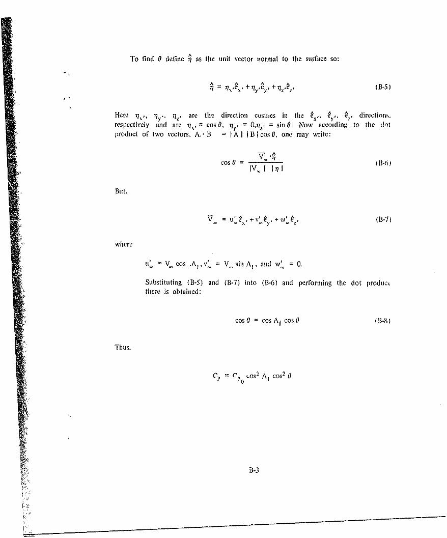
To find 0 define 7A as the unit vector normal to th. surface so:
A ,A A
77 = 7r e, x .+7 P I + 7 ,i , (1B-5)
Here )?,,, Irv. , are the direction cosi;,es in the U•-,, •,, directions.respectively and are 7r1, = cos 0., = 0,t? , = sin 0. Now according to the (lotproduct of two vectors, A.- B =A I B I cos 0, one may write:
Cos 0IV,. I 1771 ( -6)
f. But,
u'~,v' +w', (1-7)
where
U' Vcos ,A1 v' V:V sin A, and w' =0.
Substituting (B-5) and (B-7) into (B-6) and performing the (lot productthere is obtained:
cos 0 = cos A, cos 0 (B-8)
Thus,
Cp (11) (0os2 AI cos2 0
B-3
Lv

anti (B-3) becomes:
cCx os 2 A, Ry Cos r() cos3 0d dy' (B-9)
Integrating the infside integral.
S Cp Cos- Ai Sin3 0 2 c0S A
=. I ill 0 uOr L -Y!) dvr"S Sref- 3 f
If it is assumed that the leading edgc radius varies linearly from its maximum atthe root chord to its minimum at the tip chord then:
rL (YL ) = (RT - R•) X-( 2 cos A, ) + RR (B-10)
Substituting this relation into the above integral and performing the integration thereis obtained:
C bCl,0 cos AI si3 0'(B-1I
S RA VG 0 3 O (
vwhere RAVG = (Rit + R.l )/2. Equation (B-I l) is for one fin. If there are four finispresent then the axial force coefficient in thie x direction for the blunt portionof the fin is:
4Ccos A 4bCs cos 2 AIRAVG , - u (B- 2)
3B-4

APPENDIX C

TRAILING EDGE SEPARATION DRAG
The incremcnfal force on the elemental area of the wing trailing edg-e shown inthe sketch below is:
dC 'JA dy fP~ PSt P S e
TdA Ady
-k-dyTE
Cp (y)
In analogy to the work of Reference 1, an empirical expression which takes intobaccount the slope of the wing traifing edge is
CP(-,) Cp d(y_ (-2CIi) - (I, t(y) ('2
Again, assuming a linear variation of the trailing edge diameter from (dR )TI aA theroot to (di )TL at the tip, the diameter at any y location is:
(TL (y) --- )T . + dT) I.I. (d •)l j (C-3)
where
•.,• "r -- 2y~b.
Then I (Illation (C-!) bccoine":
C-I

Cp•3 b dl, : bC.B ICl I t(y) dy = , "l' dT1:(7v)dY (C-4)
Substituting (('-3) into (C-4) and integrating yields
bCp rC - T Tj (C-5)S. • 2S rerL
or ror four fins:
, (d Ir +(d.r, = ( RR)T"L +(RT)Tr] ()I-6)
(C-6
C 3
• S r rS r t
(2-
F.

."
•.. APPENDIX D
•' GLOSSARY
N)I-I
•_--•,.-,-
K •
K,.,

GLOSSARY
,Aý Aspect ratio
b Wing span (dot's not include body radius)
c Chord length at any point along span
ACj Axial force coefficient = CD
AC Axial skin-friction drag coefficient
C A Trailing edge separation drag coefficient
CD Zero lift drag cu, fficientWave drag coefficient of wing
Cd Cross-flow drag coefficient of wing
Cd Spanwise wave drag coefficientdw
Cfr Laminar ski..-friction coefficient
C IT Turbulent skin-friction coefficient
"!CM Pitching moment coefficient measured about nose tip (poaitive nose up).
!:!•CM Spanwise pitching moient of wing
C•, Pitching moment coefficient derivative (dCN,¶/da)
CN Normal force coefficient
CN Normal fore.: coefficient on tail of body shed vortex.SN13(V)
CNi Normal force coefficiuit on tail due 'o canard shed vortex.
CN Normal force cci:ffic.ent derivative (dCN/d,)
-D-1

GLOSSARY (Continued)
SCn Spanwise normal force of wvig
Cp Pressure coefficient
C Base pressure coefficient
C po Stagnation pressure coefficient
Cr1 Chord length at root of the leading edge portion of a modified doublewedge airfoil section
Cr2 Chord leigth at root of the trailing edge portion of a modified doublewedge airfoil section
•ACII Lifting pressure on wing
d Body diameter
E,F,K Edlliptic integrals
Sf Canard vortex semispan at canard trailing edge
h1 Height of canard shed vortex above body axis at tail center of pressure
Si Tail interference factor
KB Ratio of lift of body to that of wing
KR W) Ratio of lift of body in presence of wing to that of the wing alone
Kc Ratio of lift of canard-body-tail combination to that of wing alone
Kw(3 Ratio of lift of wing in presence of body to that of wing alone
k 1) (w Ratio of lift on body in presence of wing, due to a wing deflecion 6. tothat of wing alone
ki ki tanA1
2bD

GLOSSARY (Continued)
kW(b) Ratio of lift of wing in presence of body, due to a wing deflection 6, tothat of wing alone
SLC Lift of canard-body-tail combination
NM Mach number
rm in - cot A1
SRN Reynold's number
r Radius of body (variable)
rL U Radius of wing leading edge in a plane normal to leading edge
r-. Radius of wing trailing edge in a plane normal to trivhng edge
i Sref Reference area (maximum body cross-sectional area unwss wing alone isconsidered iii which case the wing planform area is used)
WS Wing planfornm area
s Wing seimspan plus bod. radius at wing root chord
STw Wall temperature
St Wing thickness (variable)
u,v'w Perturbation velocities in the x,y,z diredtions, respectively
V Total velocity, V2 (U_ + u)2 + V2 + W2
x,y,z Rectangular coordinate system with x at nose tip, , out right wing, and zpositive up. If no body is present, x begins at wing root choid.
0 Angle of attack
D-3

4 GLOSSARY (Continued)
P• Circulation at wing-body juncture of combination
7y Ratio of specific heats (y = 1.4 for air)
6 Wing deflection angk
S77r•= kj/j3 1/= n
0 Angle betwmen a tangent to the local wing surface and freestream diredtion
01 Angle on blunt leading edge where Newtonian theory stops andperturbation theowy begins (match point)
Ai Sweepback angle of a wing generator (i = 1,2,3,4) with i I the wingleading edge and i = 4 the wing trailing edge
x Ratio of tip cniord to root chord (ct/,.r)
p1 Mach angle, i = sin- 1 (I /MNi,
v Coefficient of kinematic viscosity
U o = kiy/x
\Velocity potential
x Wedge half angle (measured parallcI to freestream) of wing airfoil section.
Subscripts
a Conditions at transonit Mach number Ma = Mfb+0.0 7
b Conditions at transonic Mach number M. = Mfb + 0.14
cp Center of pressure
lb Force break Mach number
IA Infinite afteibody
D-4
t5. . . . . . . . . . . . . .

GLOSSARY (Continued)
Subscripts
i.,ininar
"NA No afterbody4,
r Root chord
"SA Short afterbody
"1" Turbulent
t Tip chord
VIS Viscous corillonenk
I Wing for which slender body values of interference lift are known.
1i Wing vith sweep for whiih representative values of interference lift aredesired
DO: Freestream conditions
D'

2
APPENDIX E
DISTRIBUTION
i7 .1
S¢