distraction osteogenesis of the midface - beach...
TRANSCRIPT

Oral Maxillofacial Surg C
Distraction Osteogenesis of the Midface
George K.B. Sandor, MD, DDS, PhD, Dr Habil, FRCDC, FRCSC, FACSa,b,c,d,e,f,T,Leena P. Ylikontiola, DDS, PhDe,f,g, Willy Serlo, MD, PhDg,h,
Robert P. Carmichael, DMD, MSc, FRCDCa,b,c,d,
Iain A. Nish, DDS, MSc, FRCDCa,b,i,
John Daskalogiannakis, DDS, MSc, FRCDCa,b,c
aUniversity of Toronto, Toronto, Ontario, CanadabThe Hospital for Sick Children S-525, 555 University Avenue, Toronto, Ontario, Canada M5G 1X8cBloorview MacMillan Children’s Centre, 170 Kilgour Road, Toronto, Ontario, Canada M4G 1R8dDepartment of Oral and Maxillofacial Surgery, Mount Sinai Hospital, Toronto, Ontario, Canada
eDepartment of Oral and Maxillofacial Surgery, University of Oulu, Oulu, FinlandfInstitute of Dentistry, University of Oulu, Box 5281 FIN-90014, Finland
gOulu University Hospital, Box 23, FIN-90029 Oulu, FinlandhDepartment of Pediatric Surgery, University of Turku, Turku, Finland
iLakeridge Medical Centre, Oshawa, Ontario, Canada
The field of pediatric oral and maxillofacial sur-
gery is continuing to evolve and is in a dynamic
phase as our understanding of growth and develop-
ment of the craniomaxillofacial complex expands.
Bone regeneration and tissue engineering technolo-
gies have been developed to treat skeletal defects
with reduced morbidity [1]. Distraction osteogene-
sis recently emerged as a technique that by its very
nature allows changes to the vectors of growth and
results in the genesis of new tissues [2]. It is a rapidly
developing area with applications in the area of
pediatric oral and maxillofacial surgery.
Distraction osteogenesis is a biologic process that
promotes bone formation between cut osseous
surfaces that are gradually separated by incremental
traction [3]. This process is initiated when forces are
applied to separate the segments and continues as
long as the tissues of the callus that forms between
1042-3699/05/$ – see front matter D 2005 Elsevier Inc. All rights
doi:10.1016/j.coms.2005.06.005
T Corresponding author. The Hospital for Sick Children
S-525, 555 University Avenue, Toronto, Ontario, Canada
M5G 1X8.
E-mail address: [email protected]
(G.K.B. Sandor).
the segments are stretched. Bone formation occurs
parallel to the direction or vector of distraction. This
process also initiates histiogenesis of the tissues
surrounding the distracted bone: cartilage, liga-
ments, muscle, blood vessels, gingiva, and nerve tis-
sue [2,4,5].
History of midfacial distraction osteogenesis
Distraction osteogenesis as it applies to the mid-
face is not a new concept. Dentists have used tech-
niques that involve the application of tensile and
compressive forces to the bones of the craniomax-
illofacial skeleton for almost 300 years. According to
Balaji [6], Fauchard described the use of an expan-
sion arch as early as 1728, a custom-made metallic
arch applied to the crowded maxillary dentition, to
widen the arches to a more physiologic form. Wescott
attempted to correct a crossbite by placing two double
clasps on the maxillary bicuspid teeth and a tele-
scopic bar to apply transverse force [6]. Similarly,
Angell [7] expanded a maxillary arch by using a
transverse jackscrew and clasps on the bicuspid teeth.
lin N Am 17 (2005) 485 – 501
reserved.
oralmaxsurgery.theclinics.com

sandor et al486
Goddard is credited with standardization of the
palatal expansion protocol with activation twice daily
for 3 weeks followed by a period of stabilization [8].
Modern clinical distraction osteogenesis of the facial
bones developed quickly once McCarthy applied
the concept to mandibular lengthening in 1992 [9].
This development led to an explosion of clinical and
research activity in the field of craniomaxillofacial
distraction osteogenesis over the past decade [10].
Distracting tubular long bones
The mechanical manipulation of bone segments
dates as far back as Hippocrates, who described the
use of external devices to apply traction to bone
[11,12]. Codivilla [13] is credited with using an
external skeletal traction apparatus after performing
an oblique femoral osteotomy to accomplish the first
lower extremity lengthening. The Siberian surgeon
Gavril Ilizarov was the first to describe a tissue-
sparing osteotomy and reliable distraction protocol
that involved the long bones of the lower extremity in
1951 [11].
Ilizarov’s protocol was unique and involved a 5-
to 7-day latency period after the osteotomy. This
critical rest period was followed with a period of
distraction applied at a rate of 1 mm per day using
four incremental distractions of 0.25 mm. The most
critical aspect of the technique described by Ilizarov
was maximal preservation of endosteum and peri-
osteum using a procedure he termed ‘‘corticotomy.’’
He described a method in which he divided two thirds
of the cortical bone of the femur with a narrow
osteotome and finally separated the bony segments
from each other by rotational osteoclasis [3]. The
gradual application of traction resulted in the tension-
stress effect that can stimulate the genesis, regenera-
tion, and active growth of living tissues as long as
there is an adequate blood supply [4,11,12].
Distraction osteogenesis involves five distinct pe-
riods: osteotomy, latency, distraction, consolidation,
and remodeling [3,4,11,12]. Osteotomy is the surgical
separation of an intact bone into two segments. It
results in a loss of continuity and mechanical in-
tegrity, which triggers the process of fracture healing.
A reparative callus begins to form within and around
the ends of the fractured bone segments.
Latency is the period during distraction osteo-
genesis that begins with osteotomy of the bone
segments and ends with the onset of traction. Latency
permits sufficient time to elapse for a callus to form
between the osteotomized bone segments [3,4].
Distraction is the period during which traction
is applied to the bony segments when new bone
or, more precisely, a distraction regenerate is formed
within the gap between the bony segments. Two
parameters can be used to tailor the distraction pro-
cess: rate and frequency. Gradual traction of the soft
callus disrupts fracture healing, and the tensional
stress stimulates changes at the cellular and subcel-
lular levels [2–5]. These changes include increased
proliferation of fibroblasts with an altered phenotypic
expression that secrete collagen fibers parallel to the
vector of distraction. Bone formation begins at the
termini of the bony segments and progresses toward
the center of the distraction gap [3].
Consolidation begins after termination of traction
[11,12]. Consolidation permits mineralization and
eventual corticalization of the newly formed bone
in the distraction regenerate and must be substantially
complete before removal of the distraction device.
Remodeling begins at the onset of functional
loading of the distracted bone. The initial bony
scaffold is reinforced by parallel fibered lamellar
bone. Gradually the cortical bone and marrow cavity
are formed. Remodeling of Haversian systems is the
last process to occur before development of com-
pletely normal bone at the site of distraction. The
process of remodeling can take more than 1 year
[11,12].
Distracting irregularly shaped membranous bones
Distraction osteogenesis can be applied to multi-
ple sites in the midfacial skeleton in pediatric and
adult populations. The application of the concepts
described in limb lengthening and the distraction of
tubular long (endochondral) bones, however, must
be modified when applied to the irregularly shaped
membranous bones of the midface [2]. Distraction
osteogenesis can be used in several areas (Box 1),
including the maxilla at the LeFort I, II, and III levels,
the nasal and zygomatic bones, and the bones that
comprise the cranium. Distraction osteogenesis can
be applied to healed bone grafts in the craniomax-
illofacial skeleton and to vertical and horizontal
defects of the maxillary alveolus.
The devices required for distraction of each of
these areas varies depending on the site and goals of
treatment. Hardware may range from large external
halo-like devices (Fig. 1) to much smaller appliances
that resemble bone fixation plates (Fig. 2) to jack-
screws that attach to the teeth (Fig. 3). The goals of
treatment and the necessary vectors used in each of

Fig. 2. Intraosseous devices configured like bone plates with a
distractor rod between them are much smaller than their halo-
like counterparts (KLS Martin, Jacksonville, Florida, USA).
Box 1. Midfacial distraction deviceclassification
External: bone-borneInternal: subcutaneousIntraoral
� ExtramucosalTooth-borne
� SubmucosalBone-borneHybrid
Classification according to distractiondirection
UnidirectionalBidirectionalMultidirectionalClassification according to site of
midfacial distractionLeFort I, II, IIINasal bonesZygomatic bonesHealed bone graftsMaxillary alveolus
� Transverse� Vertical� Horizontal
distraction osteogenesis of the midface 487
these regions are also distinct. The direction of
distraction must be well planned. Certain devices
allow distraction in more than one plane or vector
(see Fig. 1). At times, two appliances may be used
simultaneously; however, neither the devices them-
Fig. 1. A halo-like external frame device used to distract the
retrusive midface (Biomet-Lorenz, Jacksonville, Florida).
Such devices have become simple to apply, lightweight, and
based on transcutaneous pin fixation to the skull. This
device can be adapted to provide distraction vectors in more
than one plane.
selves nor their vectors of distraction should be
allowed to interfere with each other (Fig. 4).
Indications
Distraction osteogenesis is a labor-intensive and
technique-sensitive treatment modality and should be
reserved for specific indications. Distraction osteo-
genesis of the midface has two main advantages over
traditional osteotomies. It can produce larger move-
ments, and it may be associated with less relapse
than traditional osteotomies. Distraction osteogenesis
should be used for significant bony movements in the
treatment of conditions known to have high relapse
rates after traditional forms of treatment.
Distraction osteogenesis can be repeated at differ-
ent phases of life. In some cases the application of a
halo to the skull and a few simple titanium plates
screwed into the bones of the craniomaxillofacial
skeleton may be less invasive than certain osteo-
Fig. 3. Traditional tooth-borne palatal distractor. Note
diastemma between maxillary central incisors, which is site
of the palatal distraction osteogenesis. Same as Fig. 5.

Fig. 4. Two devices are used to distract at the LeFort I level.
The vectors of distraction of the devices must have minimal
convergence so they do not interfere with each other
(Synthes, Oberdorf, Switzerland).
sandor et al488
tomies, and developing tooth roots can be avoided
and left undamaged by the design of osteotomies.
Patients who have cleft lip and palate often require
significant advancement of their midface at one or
more LeFort levels. Maxillary advancement using
traditional osteotomies may place these patients at
risk for the development of velopharyngeal insuf-
ficiency [14,15]. It has been reported that this
debilitating complication may be avoided for some
of these patients if distraction osteogenesis is used
to advance the maxilla [2,16], because it can leave
the posterior dentition and velopharyngeal relation-
ships undisturbed.
Distraction osteogenesis of the midface also may
be applied to treat functional problems, such as ob-
structive sleep apnea and exposure keratitis and
corneal scarring from proptosis [17–19].
Risks associated with midfacial distraction
The risks associated with distraction osteogenesis
of the midfacial structures are similar to the risks
encountered with traditional osteotomies. Careful
preoperative planning of the vector of distraction is
essential to ensure that the distracted segment ad-
vances fully in the desired direction without interfer-
ence from surrounding bony structures or teeth.
Swennen and colleagues [10] reported complica-
tions in 828 patients undergoing craniomaxillofacial
distraction. Complications included mechanical prob-
lems, such as pin loosening caused by accidental
trauma, device failure, minor local infections, infec-
tions of the skin surrounding percutaneous pins, pre-
mature consolidation, limited skeletal advancement,
asymmetric advancement, ankylosis of zygoma and
coronoid process, severe infection, damage to teeth,
and tooth mobility.
Distraction across the midpalatal suture
The age of the patient dictates the type of
distraction that may be used to expand the maxilla.
In growing children with a transverse deficiency of
the maxilla and in whom the midpalatal suture has
not yet fused, force analogous to physeal distraction
used in orthopedics can be applied across the mid-
palatal suture [20]. Distraction of the midpalatal
suture occurs in membranous bone across a suture,
whereas physeal distraction is used in endochondral
bones across an epiphyseal growth plate.
Rapid palatal expansion, also known as orthope-
dic rapid maxillary expansion, can be performed
in girls before 15 years of age and in boys before
16 years of age [8]. If the palatal suture is fused then
tipping of teeth occurs rather than transverse expan-
sion of the maxilla [21].
Surgical widening of the maxilla must be used to
correct transverse maxillary deficiency in patients
with a fused midpalatal suture. This procedure has
been termed surgically assisted rapid palatal expan-
sion or surgically assisted maxillary expansion. Al-
though it predates all other distraction osteogenesis
procedures performed in the midface, it is often for-
gotten in the classification of midfacial distraction.
As with other distraction osteogenesis procedures,
there are five distinct phases in surgical widening
of the maxilla at the level of the midpalatal suture:
osteotomy, latency, distraction, consolidation, and
remodeling [3]. The osteotomy is performed at the
LeFort I level and involves a variable combina-
tion of surgical separation of the midpalatal suture
and osteotomy of the lateral and medial nasal walls,
nasal septum, vomer, and pterygomaxillary junction
[21–23]. The exact combination of osteotomies
varies among authors [24–31]. The latency period
is generally 1 to 2 days. Distraction is performed
using a transverse jackscrew connected to attach-
ments placed on the first molar and bicuspid teeth.
Distraction is performed with a frequency of two
increments of 0.5 mm per day (1 mm/d) until the
maxilla has been widened sufficiently. The distraction
device is kept in place for 3 months to allow for

Fig. 5. Note intersegmentary bone formed in the maxillary
midline after surgically assisted rapid palatal expansion on
this occlusal radiograph. The device has been left on after
the distraction phase to serve as a retainer during the con-
solidation phase.
distraction osteogenesis of the midface 489
consolidation. Active orthodontic treatment can re-
sume during the remodeling phase.
The surgically assisted rapid palatal expansion or
surgically assisted maxillary expansion procedure
produces intersegmental bone (Fig. 5) and creates a
stable widening of the maxillary arch, even when it is
significantly constricted (Fig. 6A, B). As in other
forms of distraction osteogenesis, distraction of the
midpalatal suture permits a larger correction than
nonsurgical orthodontic treatment could achieve.
Distraction strategies in cleft lip and palate
Distraction osteogenesis offers several advantages
over conventional osteotomies in the treatment of
patients who have cleft lip and palate. There is a
Fig. 6. (A, B) Constricted maxillary dental arch before and afte
tic alignment.
reduced tendency for significant relapse after distrac-
tion of the maxilla than after traditional maxillary
osteotomies. The soft tissue changes associated with
maxillary advancement may be superior after dis-
traction osteogenesis when compared with traditional
LeFort I level advancement surgery [32]. It is also
possible that deterioration of velopharyngeal function
may be avoided in patients at risk for its development
[2,14–16,33].
The midfacial deformities seen in patients who
have cleft lip and palate include transverse maxillary
deficiency, midfacial retrusion, and significant alveo-
lar cleft defects. Transverse maxillary deficiency in
a patient who has unilateral cleft lip and palate can
be corrected with corticotomy and distraction in a
modified procedure similar to the surgically assisted
rapid palatal expansion or surgically assisted maxil-
lary expansion technique.
Midfacial retrusion may be treated at the LeFort I,
II, or III levels. LeFort I level distraction may involve
advancement of segmentalized maxillary fragments
or the entire maxilla [34,35]. Large alveolar cleft
defects may be reduced in size using distraction
osteogenesis to transport bone segments across the
cleft [36]. Such a decrease in size of the cleft and
associated oronasal fistula may enhance the outcome
and predictability of bone grafting techniques [37].
Distraction hardware developed for anterior max-
illary segmental advancement (Fig. 7A–E) has been
used successfully in patients who have cleft lip and
palate [38,39]. A stereolithic skull reconstructed from
a three-dimensional CT scan can aid planning of such
osteotomies by permitting preoperative selection and
bending of plates, which reduce expenditures on
distraction hardware and operating room time. Pre-
operative planning also ensures that a certain configu-
ration and arrangement of the selected distraction
hardware actually produce the vectors of distraction
desired (Figs. 8–12).
r surgically assisted rapid palatal expansion and orthodon-

Fig. 7. Frontal (A) and lateral (B) view of 18-year-old man with bilateral cleft lip and palate and maxillary hypoplasia. (C)
Extensive palatal scarring put the patient at risk for developing velopharyngeal insufficiency with traditional LeFort I maxillary
advancement. Panoramic radiograph (D) and lateral cephalogram (E) of patient.
sandor et al490
Distraction hardware also has been developed for
LeFort I level osteotomies (Fig. 13A–C) in embodi-
ments designed to be used submucosally and sub-
cutaneously [40–42]. The selection of a specific
device is determined by the goals of the distraction
procedure, anatomic constraints, and the amount of
room available to accommodate placement of the
hardware. Care must be taken to avoid damaging the
developing dental follicles or tooth roots when ap-
plying such devices to the lateral wall of the maxilla.
The initiation of midfacial distraction relative to
creation of the corticotomy or osteotomy has been
studied in growing sheep [43]. In primates, a protocol
for immediate distraction that was composed of
intraoperative device activation, 10 mm of acute
distraction, and an additional 10 mm of distraction
performed at a rate of 1 mm per day was compared
with a protocol for delayed distraction that comprised
a 5-day postoperative latency followed by a 20-mm
distraction performed at a rate of 1 mm per day. There

Fig. 8. Simulation of osteotomy, distractor placement, and
advancement on stereolithic model.
Fig. 10. Occlusal photographic view of palate shows vectors
of distraction in a minimally convergent orientation.
distraction osteogenesis of the midface 491
was no evidence of relapse after immediate distrac-
tion or delayed distraction 6 months later. Neither
were significant differences noted after either dis-
traction protocol when the regenerated bone was
examined histologically, ultrastructurally, or by dry
skull analysis [44].
High level LeFort distraction osteogenesis
The treatment of patients with craniosynostotic
syndromes (eg, Crouzon [Fig. 14A–D], Apert,
Pfeiffer, and Saethre-Chotzen) includes advancement
of the midface [45]. Distraction osteogenesis can be
performed at all levels of the midface [46–48],
zygomatic bones [49], healed facial bone grafts [50],
frontal bones [51], and other bones of the cranium
[52,53]. Various distractor designs are available, but
essentially they can be grouped into two basic cate-
gories [54–59]: external halo-like devices (see Fig. 1)
and smaller internal devices (Figs. 15–18).
Proponents of external devices point out that
although these devices are large and cumbersome,
they are rigid and easily adjustable, often in more
than one plane of space. External appliances permit
Fig. 9. Distraction device fixed in position on right maxilla.
easy control of the force and direction of distraction
[55]. They can be applied easily to growing children,
and they obviate the need for rigidly fixing devices
on the lateral walls of the maxilla using screws where
developing dental follicles and roots of the permanent
dentition can be damaged. The use of these appli-
ances is associated with the risk of the fixation pins
penetrating the cranium, and pin site infections, how-
ever [56]. The social stigma associated with wearing
an external device may deter its use. External devices
also are prone to being accidentally dislodged [10].
Internal appliances are out of sight and have
minimal impact on a patient’s daily activities [59].
They are unidirectional, however, which makes dis-
traction possible in only one plane of space. Often
two internal devices must be used simultaneously on
either side of the maxilla, which increases the chance
for asymmetry and doubles the cost. Metal internal
distraction devices are rigid but require removal af-
ter the distraction process, which can be difficult
and complicated. Resorbable appliances that do not
require removal recently have become available
[60–62]. The tissues surrounding the transcutane-
ous distraction rods of the internal devices can be-
come infected.
The results of maxillary distraction at the LeFort
III level are far better than those of traditional mid-
face advancement. Fearon [45] compared 12 children
who had LeFort III distraction to an age-matched
cohort of 10 children treated by osteotomy at the
same level. The average horizontal advancement
achieved in the LeFort III distraction group was
19 mm compared with 6 mm in the LeFort III osteo-
tomy group. Two of the patients in the distraction
group with obstructive sleep apnea demonstrated ob-
jective airway improvement and two further patients
with obstructive sleep apnea were decannulated.
Fearon [45] used external and internal devices in
his cohort of patients and preferred the aesthetic
results accomplished using a halo over those obtained

}
Fig. 11. (A) Preoperative lateral cephalogram. (B) Lateral cephalogram taken immediately after operation. (C) Lateral
cephalogram taken at end of distraction phase, at beginning of consolidation phase. Note presence of bone gaps between roots of
bicuspid teeth.
sandor et al492
with internal distractors because the halo allows the
vector of distraction to be focused on the facial
midline, which helps to reposition the concave
midface and provides a more convex facial profile.
Osteotomies can be tailored to the specific aes-
thetic and functional needs of a patient. Distraction
Fig. 12. (A) Palatal view of distractors in place. Note small fistula
(B) Palatal view of right buccal segment shows distraction gap.
osteogenesis can be executed at multiple levels to
correct the occlusion and the midfacial retrusion
independently using separate devices and vectors
[63]. This is because the teeth, the nasofrontal
region, and the orbital rims may not all advance the
same distance (Fig. 18). Satoh and colleagues [63]
has opened on palate since beginning of distraction process.

Fig. 13. (A) Anterior view of large alveolar cleft with oronasal fistula. (B, C) Internal distractor is applied to right and left
osteotomized segment. (D) Occlusal view of alveolar defect preoperatively. Note two failing cleft adjacent teeth were removed
before start of distraction. (E) Postoperative occlusal view of alveolar cleft and oronasal fistula, both of which have been reduced
in size. More soft tissue is available for closure of oronasal fistula and reconstruction of alveolar defect.
distraction osteogenesis of the midface 493
recommend that the final position of the midface be
governed subjectively by the position of the nasal
bones, malar complexes, and orbital rims relative to the
rest of the face [45,63], whereas the occlusion should
be governed by an occlusal splint [63]. They also rec-
ommend osteotomizing the midface into two portions
and distracting them separately using independent
vectors and different amounts of distraction [63].
Alveolar distraction in the maxilla
Congenital absence of teeth (eg, oligodontia and
alveolar clefting) is usually accompanied by bony
defects of the maxillary alveolus. Acquired bony
defects occur after tooth extraction, periodontal dis-
ease, maxillofacial trauma, and tumor ablation. The
configuration of alveolar defects can be primarily
horizontal or vertical in nature—or a combination of
each—and can limit the restoration of missing teeth
with dental implants.
The treatment of alveolar defects includes guided
bone regeneration using various membranes, onlay
autogenous bone grafts, connective tissue grafts, and
alloplastic augmentation. Vertical alveolar defects are
difficult to overcome in a predictable manner using
autogenous bone grafts, and they often lead to aes-
thetic shortcomings [64,65]. Distraction osteogenesis
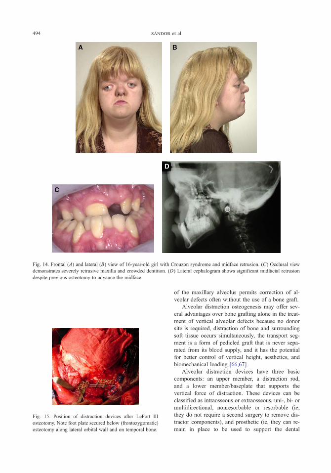
Fig. 14. Frontal (A) and lateral (B) view of 16-year-old girl with Crouzon syndrome and midface retrusion. (C) Occlusal view
demonstrates severely retrusive maxilla and crowded dentition. (D) Lateral cephalogram shows significant midfacial retrusion
despite previous osteotomy to advance the midface.
Fig. 15. Position of distraction devices after LeFort III
osteotomy. Note foot plate secured below (frontozygomatic)
osteotomy along lateral orbital wall and on temporal bone.
sandor et al494
of the maxillary alveolus permits correction of al-
veolar defects often without the use of a bone graft.
Alveolar distraction osteogenesis may offer sev-
eral advantages over bone grafting alone in the treat-
ment of vertical alveolar defects because no donor
site is required, distraction of bone and surrounding
soft tissue occurs simultaneously, the transport seg-
ment is a form of pedicled graft that is never sepa-
rated from its blood supply, and it has the potential
for better control of vertical height, aesthetics, and
biomechanical loading [66,67].
Alveolar distraction devices have three basic
components: an upper member, a distraction rod,
and a lower member/baseplate that supports the
vertical force of distraction. These devices can be
classified as intraosseous or extraosseous, uni-, bi- or
multidirectional, nonresorbable or resorbable (ie,
they do not require a second surgery to remove dis-
tractor components), and prosthetic (ie, they can re-
main in place to be used to support the dental

Fig. 16. Immediate postoperative anteroposterior cephalo-
gram before onset of distraction phase.
Fig. 18. Post-consolidation lateral cephalogram. Advancement
at incisal level was 19 mm and 8 mm at frontonasal region.
distraction osteogenesis of the midface 495
prosthesis) or nonprosthetic (ie, they must be re-
moved after distraction and replaced with a dental
implant) [68,69].
Alveolar distraction osteogenesis is indicated for
the treatment of alveolar defects in which the alveolar
Fig. 17. Frontal (A) and lateral (B) view of patient at end of consoli
correction of anterior crossbite.
processes are atrophic and deficient. Alveolar dis-
traction osteogenesis also can be used to correct
vertical defects caused by ankylosis and submergence
of primary teeth retained in the absence of succeda-
neous teeth (Fig. 19). Alveolar distraction osteo-
genesis is contraindicated in cases of severe atrophy
in which there is insufficient bone to allow safe
hardware placement between tooth roots and the floor
of the nose or maxillary sinus. It also may be
contraindicated in patients who have severe osteopo-
dation phase of distraction. (C) Postoperative occlusion with

Fig. 19. Ankylosed deciduous teeth are useful anchorage
units for attachment of tooth-borne distraction devices. Note
submergence of deciduous lateral incisors and canines.
There is a vertical discrepancy in the alveolus, which
required vertical distraction osteogenesis before dental
implant restoration.
sandor et al496
rosis in which bone quality is poor, in patients of
extremely advanced age, or in patients who are
unlikely to demonstrate compliance with the rigors of
the distraction process. The first step in alveolar
distraction is to plan the vector of distraction and
select a distractor that is capable of delivering that
force in the proper direction. If teeth are available to
anchor a distraction device then an external tooth-
borne device can be used (Figs. 20, 21A–C);
otherwise, an internal bone-borne device must be
selected. The effect of the rigid palatal tissues on the
vector of distraction should be kept in mind when
treating the maxilla. Palatal tissues tend to exert pull
on the distracting segment and cause it to tilt lingually
away from the desired vector. If ankylosed teeth are
used for anchorage of the distraction segment, they
are extracted after the removal of the distraction
hardware (Fig. 21C). Dental implants can be placed
into the distracted alveolar segment and restored in
their new ideal position (Fig. 22).
Fig. 20. Anterior view of tooth-borne distraction apparatus
to vertically lengthen maxillary alveolus.
The distracting dental implant
There are clear advantages to having a device that
can be used to correct vertical bony defects and can
serve as the anchor for a prosthesis after completion
of distraction. Such an intraosseous, prosthetic dis-
traction device with completely internalized com-
ponents is currently in the prototype stage of
development (Fig. 23). The distracting implant,
which is composed of a fixture connected to a
footing by means of a retaining screw, is placed
within the bone. When the assembly is installed
completely, the proximal surface of the footing bears
against the bottom of the osteotomy. After the
completion of the distraction process (Fig. 24), the
distracting dental implant is used to support a
dental prosthesis.
Description of the alveolar distraction process
using dental implants
The first step in alveolar distraction osteogene-
sis using a dental implant is assessment of the nature
of the bony defect. The distracting dental implant
should be used in a vertical defect up to 5 mm in
which there is sufficient bone to distract without bone
grafting. Alveolar defects with up to 10 mm of ver-
tical loss in which there is significant horizontal loss
may require bone grafting for width followed by
healing before distraction.
Distracting dental implantation is a two-stage
procedure in which the implant is placed and
permitted to heal for some months before the dis-
traction procedure commences. When sufficient
osseointegration of the fixture and the footing have
occurred, a corticotomy using an oscillating saw or
bone chisel is completed. After a latency period of
5 to 12 days, active distraction is started. To com-
mence the distraction procedure, the retaining screw
is removed and the distractor rod is placed within the
fixture (Fig. 24). The distractor rod is advanced along
the bore of the fixture until it bears against the
footing. Further rotation of the distractor rod results
in the fixture moving in the distal direction relative to
the footing. The segment of bone into which the
fixture is integrated moves in the direction of

}
Fig. 21. (A) Immediate postoperative panoramic radiograph shows device position. (B) Panoramic radiograph after distraction
device removed shows increased vertical height of alveolus and teeth. (C) Panoramic radiograph after extraction of deciduous
teeth shows increased vertical height of alveolus.
distraction osteogenesis of the midface 497
distraction [3,4]. Depending on the length of travel
along the direction of distraction, one or more
distractor rods of different lengths may be used
inside the implant.
Final bone healing occurs during the consolida-
tion period. The distractor or an external support,
such as orthodontic splinting, is used to stabilize the
segments. Thereafter, the distractor rod is removed,
which leaves a cylindrical void in the newly formed
bone that also fills in with bone. Upon completion of
the distraction, the fixture may remain in place,
Fig. 22. Panoramic radiograph after implant fixture placement.
having been firmly integrated in the bone tissue,
where it can be used to serve as an anchor for a
prosthetic crown or bridge. With the advent of new
titanium surface geometries and concomitant use of
growth factors, more rapidly developing osseointe-
Fig. 23. Distracting dental implant including fixture body,
distractor rod, and footplate represented by clear plastic disc
next to implant (CSMT, Mississauga, Ontario, Canada).

Fig. 24. Distracting dental implant activated demonstrates
gradual gains in vertical alveolar height. Distracting hard-
ware also serves as prosthetic restoration.
sandor et al498
gration may allow for implant placement and
distraction in a single stage.
Guidance of implant placement
Although the distracting dental implant is a
unidirectional distraction device, its trajectory can
be guided to a certain extent using orthodontic forces
or a prosthodontic docking station. A further con-
sequence of the unidirectional nature of the distract-
ing dental implant is that the vector of distraction is
defined primarily by the implant’s longitudinal axis.
To a certain extent, the geometry of the corticotomy
can be designed to counter pull from the lingual or
palatal mucoperiosteum. Because the trajectory of the
distracting implant depends substantially on the
vector of distraction, it is critically important to
control the spatial location and axial inclination of the
implant. An implant positioning device with the
capability of controlling spatial location and axial
inclination is currently under development.
The future of alveolar and midface distraction
osteogenesis
Distraction osteogenesis is a powerful technique
that already has revolutionized pediatric oral and
maxillofacial surgery by providing a means of re-
liably lengthening the bones of the midface and
mandible [48]. As an alternative or an adjunct to
conventional ridge augmentation procedures, alveolar
distraction osteogenesis with a distracting dental
implant offers the prospect of greater control in the
correction of vertical alveolar defects and better
aesthetic outcomes. A distracting implant also al-
lows for correction of some unsuccessful results
that otherwise might require the use of long clini-
cal crowns or pink porcelain, or, in the worst case,
removal of the implant, revisional ridge augmenta-
tion, and reimplantation.
Distraction osteogenesis may allow for earlier
implant placement in children. The most appropriate
time for implant placement in growing patients has
been discussed. Experiments designed to study the
effect of dental implants on dentoalveolar growth and
development in pigs demonstrated that implants
remain stationary and do not erupt together with
adjacent teeth [70]. Implants were found to inhibit
local growth and development of the alveolar
process, much in the same way that ankylosed teeth
behave [71]. A 3-year prospective clinical study in
adolescents with congenitally missing teeth verified
that implants do not move during jaw growth and
result in development of an infraocclusion and
vertical marginal discrepancy of the prosthetic crown
that is proportional to the amount of residual jaw
growth after implant restoration [71,72]. One case
report [73] documented a similar phenomenon
occurring over a decade in an adult, putatively caused
by continuing growth of the facial skeleton [74–76].
Standardization of implant capability to permit
distraction osteogenesis would extend the ability to
refine aesthetics in the future after late detrimental
changes related to residual alveolar growth, continued
growth of the dentoalveolar process through adult-
hood, eruption of adjacent teeth, and recession of
soft tissue.
In the future, distraction osteogenesis may bene-
fit from automation of the distraction technique by
the incorporation of a micromotor controlled by a
microprocessor to allow for smooth and continuous
distraction. Three-dimensional treatment planning
with accurate transfer will allow for proper placement
of the bony segments in three dimensions. Endoscopy
may be another future adjunct to the distraction pro-
cedure to facilitate minimally invasive surgery with
improved visualization of the osteotomy sites [77].
References
[1] Moghadam HG, Sandor GKB, Holmes H, et al.
Histomorphometric evaluation of bone regeneration
using allogeneic and alloplastic bone substitutes. J Oral
Maxillofac Surg 2004;62(2):202–13.
[2] Molina F. Distraction osteogenesis for the cleft lip and
palate patient. Clin Plast Surg 2004;31(2):291–302.
[3] Ilizarov GA. The tension-stress effect on the genesis
and growth of tissues: Part I. The influence of stability
of fixation and soft tissue preservation. Clin Orthop
1989;238(2):249–85.
[4] Ilizarov GA. The tension-stress effect on the genesis
and growth of tissues: Part II. The influence of the rate

distraction osteogenesis of the midface 499
and frequency of distraction. Clin Orthop 1989;
239(2):263–85.
[5] Komuro Y, Akizuki T, Kurakata M, et al. Histological
examination of regenerated bone through craniofacial
bone distraction in clinical studies. J Craniofac Surg
1999;10(4):308–11.
[6] Balaji S.M. History of craniofacial distraction osteo-
genesis. In: Abstracts of the Second Asia Pacific
Congress on Distraction Osteogenesis. Male (Mal-
dives): 2003. p. 1–9.
[7] Angell EH. Treatment of irregularities of the perma-
nent or adult teeth. Dental Cosmos 1860;1:540–4.
[8] Haas AJ. Rapid expansion of the maxillary dental arch
and nasal cavity by opening the midpalatal suture.
Angle Orthod 1961;31:73–90.
[9] McCarthy JG, Schreiber J, Karp N, et al. Lengthening
of the human mandible by gradual distraction. Plast
Reconstr Surg 1992;89(1):1–8.
[10] Swennen G, Schliephake H, Demf R, et al. Craniofa-
cial distraction osteogenesis: a review of the literature.
Part I. Clinical studies. Int J Oral Maxillofac Surg
2001;30(2):89–103.
[11] Ilizarov GA. Clinical application of the tension-stress
effect for limb lengthening. Clin Orthop 1990;250(1):
8–26.
[12] Ilizarov GA. The principles of the Ilizarov method.
Bull Hosp Joint Dis 1997;56(1):49–53.
[13] Codivilla A. On the means of lengthening in the
lower limbs, the muscles and tissues which are short-
ened through deformity. Am J Orthop Surg 1905;2:
353–7.
[14] Sandor GKB, Witzel MA, Posnick JC. The use of
nasendoscopy in predicting velopharyngeal function
after maxillary advancement. J Oral Maxillofac Surg
1990;48(8):123.
[15] Sandor GKB, Leeper HA, Carmichael RP. Risks and
benefits of orthognathic surgery: speech and velopha-
ryngeal function. Oral Maxillofac Surg Clin North Am
1997;9(2):147–65.
[16] Karakasi D, Hadjipetrou L. Advancement of the
anterior maxilla by distraction [case report]. J Cranio-
maxillofac Surg 2004;32(3):150–4.
[17] Uemura T, Hayashi T, Satoh K, et al. A case of
improved obstructive sleep apnea by distraction osteo-
genesis for midface hypoplasia of an infantile Crou-
zon’s syndrome. J Craniofac Surg 2001;12(1):73–7.
[18] Cohen SR, Holmes RE, Machado L, et al. Surgical
strategies in the treatment of complex obstructive
sleep apnea in children. Pediatr Respir Rev 2002;
3(1):25–35.
[19] Britto JA, Evans RD, Hayward RD, et al. Maxillary
distraction osteogenesis in Pfeiffer’s syndrome: to
provide urgent ocular protection by gradual midfacial
skeletal advancement. Br J Plast Surg 1998;51(5):
343–9.
[20] Zarzycki D, Tesiorowski M, Zarzacka M, et al. Long
term results of limb lengthening by physeal distraction.
J Pediatr Orthop 2002;22(3):367–70.
[21] Haas AJ. The treatment of maxillary deficiency by
opening of the midpalatal suture. Angle Orthod
1965;35:200–17.
[22] Pogrel MA, Kaban LB, Vargervik K, et al. Surgically
assisted maxillary expansion in adults. Int J Adult
Orthodon Orthognath Surg 1992;7:37–41.
[23] Lines PA. Adult rapid maxillary expansion with
corticotomy. Am J Orthod 1975;67:44–56.
[24] Kraut RA. Surgically assisted rapid maxillary expan-
sion by opening the midpalatal suture. J Oral Surg
1984;42:651–5.
[25] Betts NJ, Vanarsdall RL, Barber HD, et al. Diagno-
sis and treatment of transverse maxillary deficiency.
Int J Adult Orthodon Orthognath Surg 1995;10(2):
75–96.
[26] Albern MC, Yurosko JJ. Rapid palatal expansion in
adults with and without surgery. Angle Orthod
1987;57:245–63.
[27] Bays RA, Greco JM, Hale RG. Stability of surgically
assisted rapid palatal expansion. J Dent Res 1990;
69:296.
[28] Lehman JA, Haas AJ. Surgical-orthodontic correction
of transverse maxillary deficiency. Dent Clin North
Am 1990;34:385–95.
[29] Stromberg C, Holm J. Surgically assisted, rapid
maxillary expansion in adults: a retrospective long
tern follow-up study. J Craniomaxillofac Surg 1995;
23:222–7.
[30] Bell WH, Epker BN. Surgical-orthodontic expansion
of the maxilla. Am J Orthod 1976;70:517–28.
[31] Turvey TA. Maxillary expansion: a surgical technique
based on surgical-orthodontic treatment objectives and
anatomic consideration. J Maxillofac Surg 1985;13:
51–8.
[32] Harada K, Baba Y, Ohyama K, et al. Soft tissue profile
changes of the midface in patients with cleft lip and
palate following maxillary distraction osteogenesis:
a preliminary study. Oral Surg Oral Med Oral Path
Endod 2002;94(6):673–7.
[33] Scheuerle J, Habal MB. Functional impact of dis-
traction osteogenesis of the midface on expressive
language development. J Craniofac Surg 2001;12(1):
69–72.
[34] Rachmiel A, Levy M, Laufer D, et al. Multiple
segmental gradual distraction of facial skeleton: an
experimental study. Ann Plast Surg 1996;36(1):52–9.
[35] Altuna G, Walker DA, Freeman E. Surgically assisted
rapid orthodontic lengthening of the maxilla in
primates: a pilot study. Am J Orthod Dentofacial
Orthop 1995;107(5):531–6.
[36] Dolanmaz D, Karaman AI, Durmus E, et al. Manage-
ment of alveolar clefts using dento-osseous transport
distraction osteogenesis. Angle Orthod 2003;73(6):
723–9.
[37] Yen SL, Yamashita DD, Kim TH, et al. Closure of
an unusually large palatal fistula in a cleft patient by
bony transport and corticotomy-assisted expansion.
J Oral Maxillofac Surg 2003;61(11):1346–50.
[38] Cohen SR, Burstein FD, Stewart MB, et al. Maxillary-
midface distraction in children with cleft lip and pal-

sandor et al500
ate: a preliminary report. Plast Reconstr Surg 1997;
99(5):1421–8.
[39] Dolanmaz D, Karman AI, Ozyesil AG. Maxillary
anterior segmental advancement by using distraction
osteogenesis: a case report. Angle Orthod 2003;73(2):
201–5.
[40] Guerrero CA, Bell WH, Meza LS. Intraoral distraction
osteogenesis: maxillary and mandibular lengthening.
Atlas Oral Maxillofac Surg Clin North Am 1999;7(1):
111–51.
[41] Yamaji KE, Gateno J, Xia JJ, et al. New internal LeFort
I distractor for the treatment of midfacial hypoplasia.
J Craniofac Surg 2004;15(1):124–7.
[42] Kessler P, Wiltfang J, Schultze-Mosgau S, et al.
Distraction osteogenesis of the maxilla and midface
using a subcutaneous device: report of four cases. Br J
Oral Maxillofac Surg 2001;39(2):13–21.
[43] Haluck RS, MacKay DR, Gorman PJ, et al. A
comparison of gradual distraction techniques for
modification of the midface in growing sheep. Ann
Plast Surg 1999;42(5):476–80.
[44] Weinzweig J, Baker SB, MacKay GJ, et al. Immediate
versus delayed midface distraction in a primate model
using a new intraoral device. Plast Reconstr Surg
2002;109(5):1600–10.
[45] Fearon JA. The LeFort III osteotomy: to distract or
not to distract? Plast Reconstr Surg 2001;107(5):
1091–103.
[46] Marchac D, Arnaud E. Midface surgery from Tessier
to distraction. Childs Nerv Syst 1999;15(11–12):
681–94.
[47] Molina F. From midface distraction to the ‘‘true
monoblock’’. Clin Plast Surg 2004;31(3):463–79.
[48] Yu JC, Fearon J, Havlik JR, et al. Distraction osteo-
genesis of the craniofacial skeleton. Plast Reconstr
Surg 2004;114(1):1E–20E.
[49] McCarthy JG, Hopper RA. Distraction osteogenesis of
zygomatic bone grafts in a patient with Treacher
Collins syndrome: a case report. J Craniofac Surg
2002;13(2):279–83.
[50] Stelmnicki EJ, Hollier L, Lee C, et al. Distraction
osteogenesis of costochondral bone grafts in the
mandible. Plast Reconstr Surg 2002;109(3):925–33.
[51] Talisman R, Hemmy C, Denny AD. Frontofacial
osteotomies, advancement and remodeling distraction:
an extended application of the technique. J Craniofac
Surg 1997;8(4):308–17.
[52] Lauritzen C, Sugawara Y, Kocabalkan O, et al. Spring
mediated dynamic craniofacial reshaping: case report.
Scand J Plast Reconstr Surg Hand Surg 1998;32(3):
331–8.
[53] Li M, Park SG, Kang DI, et al. Introduction of a novel
spring-driven craniofacial bone distraction device.
J Craniofac Surg 2004;15(2):324–8.
[54] Maull DJ. Review of devices for distraction osteo-
genesis of the craniofacial complex. Semin Orthod
1999;5(1):64–73.
[55] Polley JW, Figueroa AA. Management of severe
maxillary deficiency in childhood and adolescence
through distraction osteogenesis with an external,
adjustable, rigid distraction device. J Craniofac Surg
1997;8(3):181–5.
[56] Mavili ME, Vargel I, Tuncbilek G. Stoppers in RED II
distraction device: is it possible to prevent pin
migration. J Craniofac Surg 2004;15(3):377–83.
[57] Havlik RJ, Seelinger MJ, Feashemo DV, et al. ‘‘Cat’s
cradle’’ midfacial fixation in distraction osteogenesis
after LeFort III osteotomy. J Craniofac Surg 2004;
15(6):946–52.
[58] Mavili ME, Tuncbilek G, Vargel I. Rigid external
distraction of the midface with direct wiring of the
distraction unit in patients with craniofacial dysplasia.
J Craniofac Surg 2003;14(5):783–5.
[59] Riediger D, Poukens JM. LeFort III osteotomy: a new
internal positioned distractor. J Oral Maxillofac Surg
2003;61(8):882–9.
[60] Cohen SR, Holmes RE, Amis P, et al. Internal
craniofacial distraction with biodegradable device
early stabilization and protected bone regeneration.
J Craniofac Surg 2000;11(4):354–66.
[61] Cohen SR, Holmes RE. Internal LeFort III distraction
with biodegradable devices. J Craniofac Surg 2001;
12(3):264–72.
[62] Burstein FD, Williams JK, Hudgins R, et al. Single
stage craniofacial distraction using resorbable devices.
J Craniofac Surg 2002;13(6):776–82.
[63] Satoh K, Mitsukawa N, Hosaka Y. Dual midfacial
distraction osteogenesis: LeFort III minus and LeFort I
for syndromic craniosynostosis. Plast Reconstr Surg
2003;111(3):1019–28.
[64] Belser U, Buser D, Higgenbottom F. Consensus
statements and recommended clinical procedures
regarding esthetics in implant dentistry. In Proceedings
of the Third ITI Consensus Conference, Gstaad,
Switzerland. Int J Oral Maxillofac Implants 2004;
19(Suppl):73–4.
[65] Simion M, Jovanovic SA, Tinti C, et al. Long-
term evaluation of osseointegrated implants inserted
at the time or after vertical ridge augmentation: a
retrospective study on 123 implants with 1–5 year
follow-up. Clin Oral Implants Res 2001;12(1):35–45.
[66] Clarizio LF. Vertical alveolar distraction versus bone
grafting for implant cases: the clinical issues. In:
Jensen OT, editor. Alveolar distraction osteogenesis.
Chicago7 Quintessence Publishing; 2002. p. 59–68.
[67] Jensen OT, Kuhlke L, Reed C. Prosthetic consider-
ations and treatment planning by classification for
alveolar distraction ontogenesis. In: Jensen OT, editor.
Alveolar distraction osteogenesis. Chicago7 Quintes-
sence Publishing; 2002. p. 29–40.
[68] Stucki-McCormick S, Moses JL, Robinson R, et al.
Alveolar distraction devices. In: Jensen OT, editors.
Alveolar distraction osteogenesis. Chicago7 Quintes-
sence Publishing; 2002. p. 41–58.
[69] Chin M, Toth BA. Distraction osteogenesis in
maxillofacial surgery using internal devices: review
of five cases. J Oral Maxillofac Surg 1996;54(1):
45–53.

distraction osteogenesis of the midface 501
[70] Odman J, Grondahl K, Lekholm U, et al. The effect of
osseointegrated implants on the dento-alveolar devel-
opment: a clinical and radiographic study in growing
pigs. Eur J Orthod 1991;13(4):279–86.
[71] Thilander B, Odman J, Grondahl K, et al. Osseointe-
grated implants in adolescents: a three year study. Ned
Tijdschr Tandheelkd 1995;102(4):383–5.
[72] Kurol J, Odman J. Treatment alternatives in young
patients with missing teeth: aspects on growth and
development. In: Koch G, Bergendal T, Kvint S, et al,
editors. Consensus conference on oral implants in
young patients: state of the art. Jonkoping, Sweden7
Institute for Postgraduate Dental Research; 1996.
p. 77–107.
[73] Tarlow JL. The effect of adult growth on an anterior
single-tooth implant: a clinical report. J Prosthet Dent
2004;92(3):213–5.
[74] Oesterle LJ, Cronin Jr RJ. Adult growth, aging, and the
single-tooth implant. Int J Oral Maxillofac Implants
2000;15(2):252–60.
[75] Bishara SE, Treder JE, Damon P, et al. Changes in the
dental arches and dentition between 25 and 45 years of
age. Angle Orthod 1996;66(6):417–22.
[76] Forsberg CM, Eliasson S, Westergren H. Face height
and tooth eruption in adults: a 20-year follow-up
investigation. Eur J Orthod 1991;12(4):249–54.
[77] Levine JP, Rowe NM, Bradley JP, et al. The
combination of endoscopy and distraction osteogene-
sis in the development of a canine midface advance-
ment model. J Craniofac Surg 1998;9(5):423–32.