diste k modeling and simulation white paper
DESCRIPTION
ABCCTRANSCRIPT

Modeling and Simulation in Embedded Systems for Off-Highway Vehicles
By Jason Mowry, DISTek® Integration, Inc.
Abstract:
Over the last decade, modeling and simulation has proven itself by providing an analytical approach to solutions for complex problems. As system complexity accelerates in the off-highway industry, the demand for reliable software and shorter development cycles grows as well. Such complexity stresses the need for modeling and simulation to become a part of the development of every off-highway vehicle. The use of analytical tools to achieve faster and better results has become a requirement to remain competitive.
In this paper, we will explain model-based software development (MBSD), which is the integration of modeling and simulation into the product development cycle. It is also commonly referred to in industry as model-based system development or model-based design. We will also discuss why MBSD is becoming a preferred development method for many features of off-highway vehicles, what advantages MBSD gives to engineers, and how modeling and simulation helps produce a shorter time to market.

www.distek.com
1. INTRODUCTION
Modeling and simulation is becoming increasingly prevalent in software development. Modeling provides a way to describe the design of the software system graphically; moreover, a well-defined, documented model can even take the place of a software design document. Simulation provides a way to test this design before implementation. Tools like MathWorks’ Simulink® and Stateflow® provide a modeling and simulation environment as well as analysis tools that can be integrated into a workflow. Such solutions assist engineering efforts to meet the seemingly impossible goal of reducing development costs and time to market, while producing more software than ever before.
Modeling and simulation has been used since the early 1990s by the aerospace and automotive industries, which found their use of microprocessors increasing rapidly. Engineers recognized the advantages of simulating multi-domain systems for the purposes of developing embedded controls. [1] The off-highway industry began adopting modeling and simulation a decade later and is now seeing increased benefits.
Model-based software development (MBSD) is a method that can be utilized to reduce defects, improve development time, and increase collaboration among engineers by leveraging modeling and simulation. The premise is to use mathematical models and control algorithms to represent the software and the physical components that are directly or indirectly controlled by the software.
This paper explores the following:
• Growing software complexity • Complexity in off-highway vehicle systems • Control models • Plant models • MBSD throughout product development • In-the-loop testing for further verification
Growing Software Complexity
Embedded software systems are growing in capability at an extraordinary rate, promoted by the increased presence of electronic controls and sensor technology due to lower costs, customer demand, and reliability. In order to meet the growing demands of automated and assisted features and the inherited complexity, engineers turn to modeling and simulation. (See Figure 1.)

www.distek.com
“It is the integrating potential of software that has allowed designers to contemplate more ambitious systems encompassing a broader and more multidisciplinary scope, and it is the growth in utilization of software components that is largely responsible for the high overall complexity of many system designs.” [2]
Complexity in Off-Highway Vehicle Systems
An increase in sensors and actuators translates to an increase in features, which facilitates a need to focus on the architecture and design to reduce the coupling of the software components. A modeling approach provides a visual representation, data flow, and visual implementation of requirements, allowing stakeholders to have a better understanding of the software. Just like an electrical schematic or hydraulic diagram contains blocks and diagrams to illustrate the functionality, software models have a similar impact.
In addition, not only does increased functionality in actuator components cause complexity to increase, but it also increases the capacity of mechanical components to fail, causing questions about how they fail, how to detect they have failed, and what to do if they do fail. [3]
To show the impact of increased complexity, consider the example of a cruise control system. Many people may only think of a cruise control system as a feature that finds the error in vehicle speed then adjusts the throttle to achieve the desired speed. [4] In many vehicle systems, cruise control has advanced well beyond this simple concept, where the application of brakes can be used going down a hill[5], or the use of radar can keep the vehicle a safe following distance from an object ahead[6]. Many systems also include safety interlocks to detect errors such as loss of control through steering angle [7]. And the complexity is not slowing down. Expect to see fuel-efficient, adaptive control systems that use terrain maps and GPS, as well as detection of road friction and wind gusts, among other things, to eliminate transients in speed control and decrease fuel consumption.
Figure 1: Research shows an increase in the adoption of modeling tools.

www.distek.com
Product development now emphasizes the system level approach. Engineers are pressured to work across multiple disciplines, including software controls. For example, a hydraulic engineer is expected to understand the software as well as the software engineer understands the hydraulics. Therefore, software needs to adapt to become more:
• Readable for other engineering disciplines • Maintainable to allow easier transfer of knowledge • Extensible to add in new technologies as they are being created • Testable throughout the development cycle
We can achieve such goals by implementing modeling and simulation.
2. Controls and Plant Modeling using MBSD for Early Verification
Control Modeling
Control modeling is graphically representing the software that controls a system. Low-level considerations, such as writing to particular sections of memory or writing to processor port pins, can be taken into account. However, in general, application is directed to algorithm implementation, interlock and safety control, signal processing such as filtering, user interface control strategy, and closed-loop control.
Currently, most systems utilize existing drivers and legacy operating systems. This means levels of abstraction must be employed for software that is simulated as well as used in the actual system. Abstraction is a way of removing detail or simplifying a problem or concept [8]. Abstraction layers should always be evaluated to determine if simulation is going to properly reflect the real-world application. The more abstraction applied, the lower the fidelity of the simulation.
Initial analysis might lead one to believe that all functionality should be modeled, removing all abstractions. This can have a negative impact on schedule without gaining much in terms of ability to test more of the system in the simulation. Also, many engineers prefer utilizing abstraction for readability, portability, and reuse.

www.distek.com
Using an abstraction method similar to the picture shown in Figure 2, engineers are free to develop hardware drivers, manage memory, and use OS features without compromising the opportunity of early verification. Hand code (traditional C code and not auto-generated) can still control some of the functional features and fits at the application layer with the generated code.
To integrate the generated code, some configurations must be applied to the model to use it. To access the generated code, the interface layer may be part of the generated code or a hand-coded layer may be created. This interface layer can be used exclusively by the generated code or by the entire application layer. Once a process of integrating code is put in place, the effort to employ generated code is minimal.
By developing the software with a tool like MathWorks’ Simulink, engineers have an environment where design, analysis, architecture, and simulation can all be done. Traditional testing methods like open-loop simulations provide valuable information about missing implementations of requirements, dead code, or ensuring the code does what the author intended. However, with software doing so much more, this creates a need for the simulations to do more too. “One can no longer add controls onto mechanical systems as an afterthought.” [9] This illustrates the need to introduce system validation earlier and into simulations.
Plant Modeling
Plant modeling can be done in a few ways. One approach is the use of time-based mathematical descriptions called dynamic models, which use the principles of the underlying physics. Common representations of dynamic models are created using differential algebraic equations. Another method called empirical modeling or system identification utilizes test data to create transfer functions that represent a particular system [10].
Figure 2: Typical abstraction hierarchy using existing OS features

www.distek.com
Engineers utilizing component modeling methodology can separate a large system model into smaller pieces allowing different configurations and easier updating and testing, similar to how a software project would be broken down. Because of this, there would not be a division between different domains of a physical system. For instance, instead of separating hydraulics from powertrain, one would more likely have a separation between a transmission and an engine. The number of physical domains then applies to varying levels of fidelity.
Using the previous example of a cruise control system, one should realize there must be a representation of an engine, transmission, tire to ground interaction, and body dynamics to properly simulate the system. Some components may be simplified as a very low fidelity model, but each component must exist. Engineers must decide and collaborate to determine which domains (mechanical, electrical, hydraulic, magnetic, pneumatic, or thermal) are important for their software testing.
An important realization is that at times an engineer may not understand the proper boundary conditions, or in other words, make assumptions that perhaps they should not have. This is why testing on the physical prototype remains important. As the software is updated for the real world, it is important that these discrepancies do not compromise the ability to have meaningful simulations. Therefore, engineers must make sure the software used in the real-world is tied to the simulations, and data gathered from the real world validates how the plant models react. Closing this loop is the premise of MBSD.
Model-Based Software Development
MBSD is utilizing modeling and simulation for software development while assuming that the physical system is well defined and immutable. The control models are created to verify the design, and even validate certain requirements within a simulation and analysis environment. The design can become more reliable if it is automatically implemented into the software. This leads to one of the most significant parts of MBSD: automatic code generation.
Automatic code generation is how the software on a controller is directly tied to the models simulated during design. Some new adopters of MBSD may falsely believe that simply using automatic code generation saves time by skipping the step between design and implementation.
Automatic code generation does not skip a step in development to save time; rather, it links development steps to streamline the process. In traditional code development, the code is often written before the design is complete, usually saving some time. But when the design needs to be updated, it usually does not reflect what the code is actually doing; thus, more time is spent trying to add functionality into the code instead of reworking the design. In MBSD more time is spent on design. With automatic code generation, the design now can be tied to the implementation. MBSD becomes very useful when redesigns in software are needed after testing on a controller. MBSD ensures the changes make it back to design and are not just changed in implementation. Historically, the code disconnect causes the architecture and design to become obsolete and unreliable. Now, software and
www.distek.com
even mechanical and system engineers who need to understand the software can always go back to the “single source of truth”. [11]
In this paper we discuss MBSD, where other papers may use MBD (Model-Based Design). The distinction is that MBD does not assume mechanical designs are well-defined, so the team is able to develop the software but also the mechanical system. This is a great strategy and a step that comes after MBSD, but will not be discussed in this paper.
Regardless of whether the physical design is changing or not, simulations need to be verified in the real world. Even though final verification must always be at the machine level, engineers often rely too heavily on testing during development on the physical machine, which can cause changes that are time-intensive and costly at this point in the process. Often times a prototype that is required to do this testing is unavailable or may not even be built yet. MBSD allows testing to be done at varying levels leading up to full machine testing.
3. Tying in the Physical World
Model, Software, and Hardware in-the-Loop
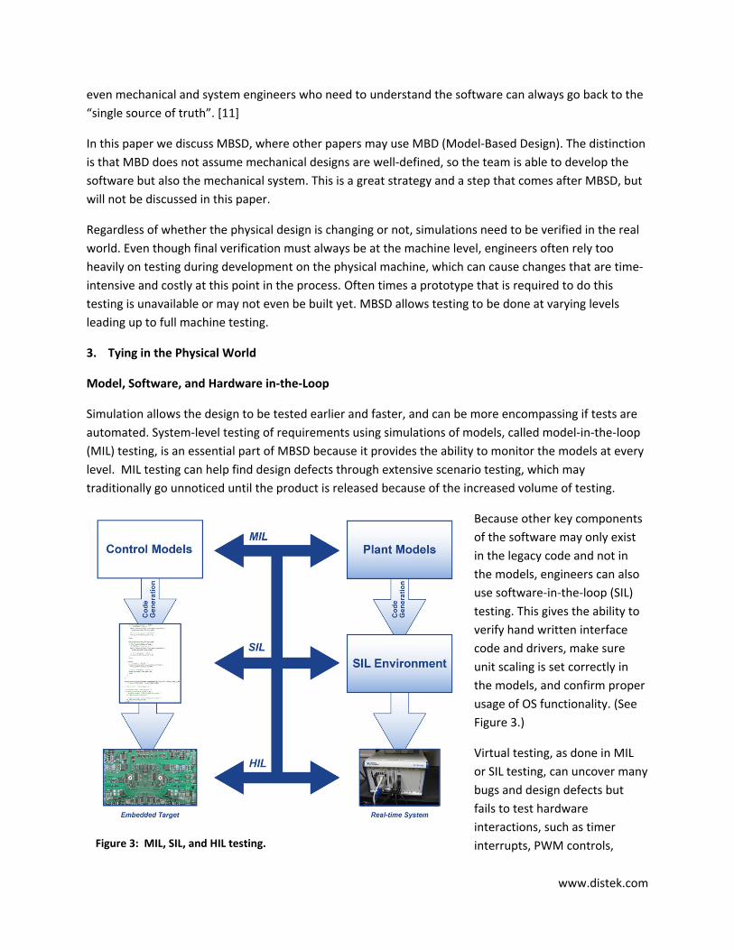
Simulation allows the design to be tested earlier and faster, and can be more encompassing if tests are automated. System-level testing of requirements using simulations of models, called model-in-the-loop (MIL) testing, is an essential part of MBSD because it provides the ability to monitor the models at every level. MIL testing can help find design defects through extensive scenario testing, which may traditionally go unnoticed until the product is released because of the increased volume of testing.
Because other key components of the software may only exist in the legacy code and not in the models, engineers can also use software-in-the-loop (SIL) testing. This gives the ability to verify hand written interface code and drivers, make sure unit scaling is set correctly in the models, and confirm proper usage of OS functionality. (See Figure 3.)
Virtual testing, as done in MIL or SIL testing, can uncover many bugs and design defects but fails to test hardware interactions, such as timer interrupts, PWM controls, Figure 3: MIL, SIL, and HIL testing.

www.distek.com
communication between controllers, and other possible real-time applications that may exist in an embedded controller, such as pre-emptive task scheduling, hard real-time A/D sampling, or watchdog interlocks. In hardware-in-the-loop (HIL) testing, the plant models run on real-time controllers that emulate the physical world by applying voltages to the embedded controller (see Figure 3). Solenoids, resistors, and actual harnesses can also be used providing an environment that the controller can execute exactly the same as when used on the physical system. Even entire components of hardware can be added or applied in a test cell. Each phase adds to the realism of the tests. [12, 13]
Not every method of in-the-loop testing needs to be, or should be, applied for each project. One advantage of in-the-loop testing is that the tests can be reused across each testing phase. This can be a great benefit especially on large projects. Smaller projects can be very successful with only MIL and HIL testing.
Looking at the different levels of testing and where they are typically conducted, it is important to realize the cost to fix defects early in the development cycle rather than later (See Figure 4). Thus, while HIL testing may find more defects, the cost becomes higher and higher as the development matures, illustrating why finding defects early in the development process is greatly preferred.
Model Validation
In-the-loop testing can be a powerful and effective way to validate the control models. However, the correctness of the control models is dependent on the correctness of the plant models. Therefore, at some stages it is important to also validate the plant models. There are many methods of doing this, and some can be as simple as running the same scenarios in the in-the-loop tests as on a physical prototype or test cell. Getting similar results validates portions of the plant model. Additional tests, which may not have much effect on the software, could be required to characterize the plant models.
Figure 4: Relative costs associated with defect detection stages.

www.distek.com
The validation of plant models is a vital step that should be planned well in advance, as it can be difficult to get access to a prototype. Skipping this step is ill advised because not incorporating real-world data jeopardizes the usefulness of the simulations and the models may become stagnant and unusable for maintenance releases or extending functionality.
The DISTek Difference
When companies are new to MBSD or are looking to expand their capabilities, it helps to have a partner that understands the practices and methodologies of modeling and simulation. DISTek specializes in all
phases of embedded software development. A classic development method called the V-cycle is expanded Figure 5 to show how modeling and simulation can integrate into this product development life cycle. Similarly, any software development life cycle can be adopted to use modeling and simulation without changing the core stages of that software development life cycle. DISTek works with client engineering teams to apply modeling and simulation to development by leveraging DISTek’s unique expertise in:
• Off-Highway Applications: DISTek has produced hundreds of successful off-highway engineering projects. The experience derived from these projects leads to better quality systems, faster development, quicker training on new systems, and ultimately better solutions.
• Embedded Systems Development: Because DISTek takes a comprehensive approach to software development, we can apply modeling and simulation into your product development. Customers only interested in modeling and simulation can benefit from our approach that understands how to fully use modeling and simulation for each step. DISTek understands the importance of well-designed models that will be future proof, maintaining the idea of the single source of truth.
• Defining Fidelity: DISTek’s vast experience in developing software controls for off-highway vehicle systems gives us the ability to understand how detailed the test systems must be in order to properly validate a system at the early stages of development. This helps to make sure the benefits of MBSD are fully realized.
Figure 5: The DISTek V-cycle.

www.distek.com
• Applying Modeling and Simulation Tools: DISTek has the experience using and applying modeling and simulation tools, including applying field data to simulations, importing existing control systems to simulations, and applying automatically generated code from models to existing operating systems and drivers. DISTek is a proud Systems Integrator Partner with MathWorks.
Where to start: The most common question companies have for using modeling and simulation is based on where to start. Having a partner like DISTek can help your company find the areas that would have the biggest impact. Daunting problems can be broken down into manageable solutions, resulting in reduced expenditures and faster time to market.
Start improving your development today. Contact a DISTek engineer at [email protected] or get more information at www.distek.com.
About the Author
Jason Mowry is the manager of Model-Based Software Development at DISTek Integration, Inc. Jason has successfully led and managed projects involving control systems with fault and interlock controls design and integration, advanced algorithm development, development of physical models for simulation, and development of interfaces and architecture for complex embedded software systems in off-highway applications.
Jason Mowry MBSD Lead Engineer 6612 Chancellor Drive Cedar Falls, IA 50613 Tel: 319-859-9272 [email protected]

www.distek.com
References
1. Broy, M.; Krcmar, H.; Zimmerman, J.; Kirstan, S.: Model-based Software Development – Its Real Benefit. EETimes, March 3, 2011
2. Lyu, M.: Handbook of Software Reliability Engineering. New York City: McGraw-Hill, 1996 3. Costlow, T.: Programmed for Safety and Reliability. SAE OHE, November 3, 2011 4. Wiggins, K.; Wright, D.: Engine Electronic Throttle Control with Cruise Control Feature. US Patent
5086740 5. White, L.: Cruise Control Economizer. US Patent 5944766 6. Sugano, T.; Etori, N.: Cruise and Vehicle-following Control System including Double Brakes. US
Patent 8078382 7. Alden, R.; Churilla, R.: Vehicular Safety System Including Automated Cruise Control Disengagement
and Warning Signals. US Patent Application US 2006/0191730 A1 8. Ganssle, J.; Barr, M.: Embedded Systems Dictionary. San Francisco: CMP Books, 2003 9. Morey, B.: ‘Simulate, then Design’ Emerges as New Engineering Methodology. SAE OHE, September
1, 2011 10. Franklin, G.; Powell, D.; Emami-Naeini, A.: Feedback Control of Dynamic Systems, Fifth Edition.
Upper Saddle River, NJ: Pearson Education, Inc, 2006 11. Ledin, J.; Dickens, M.: Automatic Embedded Code Generation from Simulation Models. RTC
Magazine. http://rtcmagazine.com/articles/view/100276, December 2004 12. Gegic, G.: In-the-Loop Testing Aids Embedded System Validation.
http://www2.electronicproducts.com, August 3, 2009 13. Kluge, T.; Allen, J.; Dhaliwal, A.: Advantages and Challenges of Closed-Loop HIL Testing for
Commercial and Off-Highway Vehicles. SAE Commercial Vehicle Engineering, SAE Technical Paper Series, No. 2009-01-2841.