distance
DESCRIPTION
notesTRANSCRIPT

Distance :
DEWA : (Distance protection schemes currently use a direct intertrip, which results in ahybrid scheme when applied to Permissive Overreach schemes. Blockingschemes in the past were equipped with an additional protection-signallingchannel due to the inherent security risk with these schemes. Blocking schemeswill no longer be used as they are functionally less secure and are slower thanPermissive Overreaching Transfer Trip (POTT) schemes.)
Distance zones :
- Zone one extension ZP when auto reclouser is used to ensure instant trip for whole line .
- Zone 1 Setting
Electromechanical/static relays usually have a reach setting ofup to 80% of the protected line impedance for instantaneous Zone 1 protection. For digital/numerical distance relays,settings of up to 85% may be safe. The resulting 15-20% safety margin ensures that there is no
risk of the Zone 1 protection over-reaching the protected line due to errors in the currentand voltage transformers, inaccuracies in line impedance data provided for setting purposes and errors of relay setting and measurement
- Z1 X : no communication Stepped time/distance characteristicsIF WE HAVE FAULT IN THR 20 % IT WILL CLREAD FIRST ZONE-1 AND ZONE-2 THAT WILL
This scheme is intended for use with an auto-reclose facility, or where no communications channel is available, or the channel has failedThe Zone 1 elements of the distance relay have two settings. One is set to cover 80% of the protected line length as in the basic distance scheme. The other, knownas 'Extended Zone 1'or ‘Z1X’, is set to overreach the protected line, a setting of 120% of the protected line being common. The Zone 1 reach is normally controlledby the Z1X setting and is reset to the basic Zone 1 setting when a command from the auto-reclose relay is received This situation cannot be tolerated in some applications,for two main reasons:
A. faults remaining on the feeder for Zone 2 time may cause the system to become unstable
B. where high-speed auto-reclosing is used, the nonsimultaneous opening of the circuit breakers atboth ends of the faulted section results in no 'dead time' during the auto-reclose
cycle for the fault to be extinguished and for ionised gases to clear. This results in the possibility that a transient fault will cause permanent lockout of the circuit breakers at each end of the line sectionEven where instability does not occur, the increased duration of the disturbance may give rise to power quality problems, and may result in increased plant damage
faults remaining on the feeder for Zone 2 time may cause the system to become unstable where high-speed auto-reclosing is used, the non simultaneous opening of the circuit breakers at both ends of the faulted section results in no 'dead time'during the auto-reclose cycle for the fault to be extinguished and for ionised gases to clear. This results
RELAY TRIP , INTIATE THE AUTORECLOUSERE , AUTOR RELCOUSE INTIATE THE Z1 B in the end of reclaim time . The disadvantage of the Zone 1 extension scheme is thatexternal faults within the Z1X reach of the relay result intripping of circuit breakers external to the faulted section,increasing the amount of breaker maintenance needed andneedless transient loss of supply to some consumers
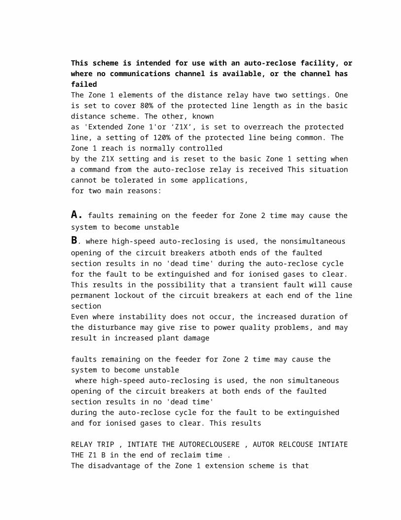
The curve drawn based on line angel
ZONE 2 SETTING : 0.3-0.5
To ensure full coverage of the line with allowance for the sources of error already listed in the previous section, the reach setting of the Zone 2 protection should be at least 120% of the protected line impedance. In many applications it is common practice to set the Zone 2 reach to be equal to the protected line section +50% of the shortest adjacent line.
Min = 120% protected line , max=100% protected line + 50 % of short line IN CASE OF REVERSAL CURRENT WE WILL PROVIDE CURRENT REVERSAL GUARD
Zone 3 Setting0.5-0.8
Remote back-up protection for all faults on adjacent lines can be provided by a third zone of protection that is time delayed to discriminate with Zone 2 protection plus circuit breaker trip time for the adjacent line. Zone 3 reach should be set to at least 1.2 times the impedance presented to the relay for a faultat the remote end of the second line section.
1.2times the sum of the protected line impedance and the impedance of the longest adjacent line ( 120% of the protective lines )
It must ensure that the relay that are seen by zone 2 of the remote end relay are also seen by the zone 3 of the local relay , to prevent tripping of the healthy line for external faults . it is recommended that reverse zone 3 reach be set directionally in the reverse direction to the same value as zone 2 setting of the remote end relay .
( reverse reach ):To protect the local bus bar 1- make zone 3 with offset ( non directional zone)2-
Zone 3 problems ( virtual faults )Load Encroachment:Encroachment of load into the zone 3 characteristics is one of the main cause for the maloperation of the relays, The mal-operation of zone 3 impedance relays with mho characteristics is a factor for causing cascading failures as seen in several previous large scale blackouts. This mal-operation could be due to the increase of the load level to the limit thatthe relay interprets the system voltage and current into an impedance that its value appears to the relay as if it is a fault while it is not, e.g. load encroachment,
When using the impedance pickup function on long heavily loaded lines, the risk of encroachmentof the load impedance into the tripping characteristic of the distance protection
may exist. To exclude the risk of unwanted fault detection by the distance protection
during heavy load flow, a load trapezoid characteristic(setting R Load and ϕ Load may be used to cut the area of the load impedance out of the polygon may be set for tripping)characteristics with large R-reaches, which excludes such unwanted fault detection by
POWER SWING :
Two kind :1- stable power swing 2-unstable power swing ( out of step tripping)-measured by dz/dt-modern relays has blocking for power swing and the calculated tripping during unstable
power swing (out-of-step tripping). At particular locations in the system, out-of-step tripping devices are also applied to split the system into islanded networks at selected locations,when system stability (synchronism) is lost due to severe (unstable) power swings.
Defenation : Following dynamic events such as load jumps, short-circuits, reclose dead times orswitching actions it is possible that the generators must realign themselves, in an oscillatorymanner, with the new load balance of the system. The distance protection registerslarge transient currents during the power swing and, especially at the electricalcentre, small voltages . Small voltages with simultaneous large currentsapparently imply small impedances, which again could lead to tripping by the distanceprotection. In expansive networks with large transferred power, even the stability of theenergy transfer could be endangered by such power swings
System power swings are three phase symmetrical processes. Therefore in general acertain degree of measured value symmetry may be assumed. System power swingsmay however also occur during unsymmetrical processes, e.g. during two-phaseshort-circuits or during single-pole dead times.
Even if a power swing has been detected, any subsequent short-circuits will result in the fast cancellation of the power swing block in the affected phases, thereby allowing the tripping of the distance protection , due comparator for each phase Power swing timer is around 30 to 90 ms
Different between power swing and fault:
The rate of change of the impedance vector is very important for the differentiationbetween faults and power swing conditions. This is shown in Figure 2-35. During thepower swing the measured impedance from one sample to the next has a definedchange in R and X, referred to as dR(k) and dX(k). Important is also the fact that fromone sample to the next the difference is small: i.e. |dR(k) – dR(k+1)| < threshold.
During a fault entry there is a rapid change that will not cause the power swing detectionfunction to pick up
for out of step : if the power swing locus moved between the three zone A,B, and the load
Since the Metal-Oxide Varistors (MOV) bypass level is normally set between 2-3In, they will notoperate during the power oscillations and therefore in majority of applications will not makeany impact on Out of Step operation.Consider a worst case scenario when the power oscillations are triggered upon faultclearance on the parallel line. In that case approximately twice the load current will startflowing through
compensation factor :the compensation factor better to measure that to ignore high ground or low ground fault to due to wrong measured
k=zo/zlK=(Z0-Z1)/3Z1
soil resistivity
starting elements :- for the static and electro mechanical relays .
1- Current starting.2-under voltage starting 3-impedence starting

But for Numerical distance relays permit direct detection of the phases involved in a fault.
This is called faulted phase selection, often abbreviated to phase selection.Several techniques are available for faulted phase selection, which then permitsthe appropriate distance-measuring zone to trip. Without phase selection, the relayrisks having over or underreach problems, or tripping three-phase when singlepolefault clearance is required. Several techniques are available for faulted phaseselection, such asa- superimposed currentb-change in voltage magnitude C-change current magnitude
voltage instability :
120( protected + longest line )
Zone 4 : forward-looking zones (typically zone--3) could be set with a small reverse offset reach from the origin of the R/X diagram, in addition to its forward reach setting. One advantage of a non-directional zone of impedance measurement is that it is able to operate for a close-up, zero impedance fault, in situations where there may be no healthy phase voltage signalor memory voltage signal available to allow operation of a directional impedance zone. With the offset-zone time delay bypassed, there can be provision of ‘Switch- On-To-Fault’ (SOTF) protection.
POWER SWING BLOCK CHECK(78) :
Power swings may occur after disconnection of heavy loads or trip of big generationplants.Power swing detection function is used to detect power swings and initiate block ofselected distance protection zones. Occurrence of earth fault currents during a power swing canblock the power swing detection function to allow fault clearance. Its principle of operation isbased on the measurement of the time it takes for a power swing transient impedance to passthrough the impedance area between the outer and the inner characteristics. Power swings areidentified by transition times longer than a transition time set on corresponding timers. Theimpedance measuring principle is the same as that used for the distance protection zones. Theimpedance and the characteristic passing times are measured in all three phases separately. Oneout-of-three or two-out-of-three operating modes can be selected according to the specific systemoperating conditions.Power swing condition simulated and checked in HMI : OKZout to Zin impedence traveling time 55msPSD is detected and less than 55ms relay is Tripping.
POWER SWING CHECKING :Checked by Ramp file for detection of Power Swing:
Power Swing turns into fault by slowing down the impedance vector :
Power Swing Boundary Checking:
Relay measures swing vector in 5 ms interval. So resistance value of the impedance vector is to be measured 5 ms before Power Swing is detected and the value of R should be approximately 5 Ω over highest zone, Z5 – Ω
Power Swing Blocking Checking:
Power Swing operating mode (Address 2002) is selected as all zones blocked and observe that relay does not trip.
Power Swing operating mode (Address 2002) is selected as Z2 to Z5 blocked and observe that relay trip in Z1.
ECHO FEATURE:Relay should not detect any fault. ECHO will be sent on receipt of carrier (If there is a fault,
ECHO will not be sent, If there is a Forward fault, no ECHO will be sent but carrier will be
sent for Teleprotection).
Relay sends ECHO signal with the receipt of CR only when there is no fault detection by the
distance protection function:

Trip / ECHO delay after carrier receipt checked : mSecs
Trip Extension / ECHO Inpulse Time checked : mSecs
Blocking feature checking :
a) ZSchemeCommunication(PSCH,85) Test :A distance relay is said to under-reach when the impedance presented to it isapparently greater than the impedance to the fault.Percentage under-reach is defined as:Under reach percent = (ZR-ZF)/ZR
In a permissive underreach scheme, a forward directed underreach measuring element (normally zone1) sends apermissive signal CS to the remote end if a fault is detected in forward direction.

The received signal CR is used to allow an overreaching zone to trip after the tCoord timer has elapsed. The tCoordin permissive underreach schemes is normally set to zero.Distance Communication Scheme (PUR) Checked : OKTcoord setting : 0.0 msDistance Aided Trip / ZCOM Trip Time : 23.7ms
b) ZSchemeCommunication(PSCH,85) Test :
A distance relay is said to over-reach when the apparent impedance presented toit is less than the impedance to the fault
In a permissive overreach scheme, a forward directed overreach measuring element (normally zone2) sends apermissive signal CS to the remote end if a fault is detected in forward direction.The received signal CR is used to allow an overreaching zone to trip after the settable tCoord timer has elapsed. ThetCoord in permissive overreach schemes is normally set to zero.Distance Communication Scheme (POR) Checked : OKTcoord setting : 0.0 msDistance Aided Trip / ZCOM Trip Time : 26.7ms
c) ZSchemeCommunication(PSCH,85) Test :The principal of operation for a blocking scheme is that an overreaching zone is allowed to trip instantaneously afterthe settable co-ordination time tCoord has elapsed, when no signal is received from the remote terminal.Distance Communication Scheme (BLOCK) Checked : OKTcoord setting : 0.0 msDistance Aided Trip / ZCOM Trip Time : 26.7ms
Starter ( switch distance relay )
Furthermore, protection against earth faults may require different characteristics and/orsettings to those required for phase faults, resulting in additional units being required. Atotal of 18 impedance-measuring elements or algorithms would be required in a fulldistance relay for three-zone protection for all types of fault
all involve recognising that the movement of themeasured impedance in relation to the relay measurement characteristics is at arate that is significantly less than the rate of change that occurs during faultconditions.
Voltage Transformer Supervision:
Appearing of zero sequence or negative sequence voltage without without the presence of zero and negative current means This arrangement will not detect the simultaneous loss of all three voltages and additional detection is required that operates for loss of voltage with no change incurrent, or a current less than that corresponding to the three phase fault current under minimum fault infeed conditions.

DUE TO ZERO sequence mutual inductance , it is possible to use the negative sequence detection instead of zero sequence due to low negative impedance comparing to zero sequence impedance . K FACTOR :
K factor( residual impedance factor ) : due to difference of earth impedance and conductor impedance the relay needs correction factor to indefy the earth fault .
K=(Z0-Z1)/3Z1
Tele protection :
Under reach :A distance relay is said to under-reach when the impedance presented to it isapparently greater than the impedance to the fault
Direct Under-reach Transfer Tripping Scheme:A see ZONE -1 fault send intrtrip to operate in zone
A 80% B
B: ZONE -1 , THEN SEND SIGNAL TO RELAY ON A TO TRIP , the under reaching is ACCERALTE the fault Permissive Under-reach Transfer Tripping:

The permissive transfer trip should only send for faults in the “Forward” direction
A SEE ZONE-1 , B SEE ZONE -2 OR ZONE-3 ( BOTH RELAY MUST DETECT THE FAULT ) Z1 SEND AND TRIP

Z2 START + RECIVE FROM THE REMOTE + TIMER OF THE SIGNAL NOT THE STEPED ZONE .
THE DIFFERENT BETWEEN DIRECT AND PERMISSIVE IS THE DIRECT IS NOT LOOK FOR REMOTE RELAY , NEED ONE RELAY TO START BUT , PERMISSIVE NEED TO BOTH RELAY DETECT THE FAULT ONE Z1 THEN SEND TO RELAY B IF IT IS DETECE THE FAULT ZONE 2 OR 3 SO IT WILL TRIP
When the circuit breaker at one end is open, or there is a weak infeed such that the relevant relay element does not operate, instantaneous clearance cannot be achieved for end-zone faults near the 'breaker open' terminal unless special features are included,
Permissive OVER -reach Transfer Tripping:
The permissive overreach transfer trip only functions for faults in the “forward” direction.
If distance relays with mho characteristics are used, the scheme may be more advantageous than the permissive under-reaching scheme for protecting short lines, because the resistive coverage of the Zone 2 unit may be greater than that of Zone 1.
To prevent operation under current reversal conditions in a parallel feeder circuit, it is necessary to use a current reversal guard timer to inhibit the tripping of the forwardZone 2 elements
If the distance protection recognizes a fault inside the overreaching zone Z1B, it initiallysends a release signal to the opposite line end. If a release signal is receivedfrom the opposite end, a trip signal is forwarded to the trip logic
POTT CHECKS:POTT Scheme Checking – Relay sends carrier for faults within Z1B only. Relay trips in Z1B time with carrier receive
for faults in Z1B else in Z2 time without carrier receive.
Transient BlockingIn the overreach schemes, the transient blocking provides additional security againsterroneous signals due to transients caused by clearance of an external fault or by faultdirection reversal during clearance of a fault on a parallel line.The principle of transient blocking scheme is that following the incidence of an externalfault, the formation of a release signal is prevented for a certain (settable) time. In thecase of permissive schemes, this is achieved by blocking of the transmit and receivecircuitIf, following fault detection, a non-directional fault or a fault in the reverse direction isdetermined within the waiting time Transient blocking ,the transmitcircuit and the release of the overreaching zone Z1B are prevented. This blocking ismaintained for the duration of the transient blocking time __'!%_'!_ %____ (address____) also after the reset of the blocking criterion. But if a trip command isalready present in Z1, the transient blocking time __'!%_'!_ %____ is terminatedand thus the blocking of the signal transmission scheme in the event of an internal faultis prevented.

voltage supervision :Modern distance protection relays employ voltage supervision thatoperates from sequence voltages and currents. Zero or negative sequencevoltages and corresponding zero or negative sequence currents are derived.Discrimination between primary power system faults and wiring faults or loss ofsupply due to individual fuses blowing or MCB’s being opened is obtained byblocking the distance protection only when zero or negative sequence voltage isdetected without the presence of zero or negative sequence current
in case of weak infeed the VT aux contact is used .
Communication Media: The communication is enabled via direct optical fibre connections or communication networks. Which kind of media is used, depends on the distance and on the communication media available. For shorter distances a direct connection via optical fibres having a transmission rate of 512kBit/s is possible.
Areva P443 In quadrilateral, but in Siemens polygon
The characteristic is provided with forward reach and resistive reach settings that areindependently adjustable, It therefore provides better resistive coverage than anymho-type characteristic for short lines. This is especially true for earth faultimpedance measurement, where the arc resistances and fault resistance to earthcontribute to the highest values of fault resistance
____________________________________________________________________________
DEWA Quality Producer:
General:
1 - download default file then adopt the setting 2- Generate RIO ( relay interface by omicrom ) file from relay and use it in omicron to generate the zone reach test module & time test module for both Phase and Earth faults for the active Zones. for the siemen

relay shall be , The XRIO Converter is not compatible with the XRIO settings export from DIGSI versions prior to 4.81.
As the following :Start a new OMICRON Control Center (OCC) document or open an existing OCC document.2. Insert a new test object or open the existing test object.3. On the File menu, click Import.4. Browse to the actual "Siemens 7UM62x ENU.xrio" file and click Open.5. Enter all necessary relay settings into the XRIO Converter block Relay Parameter Section orimport them using the import filter (see section Relay Setting Import Filter)6. Enter all necessary data in the Additional Information into the following blocks General, PowerSystem Data and Circuit Breaker Data, Test Parameter blocks (see section AdditionalInformation)7. If a parameter is "blocked" in the relay settings, set it to +inf in the XRIO Converter to deactivateit.8. Click OK
*****If the direction of the Earthing is Towards the line ( Cable ):
The Current is Lagging the Voltage by 45° ( As shown below )
( ii ) If the direction of the Earthing is Towards the Bus Bar:
The Current is Leading the Voltage by 135° ( As shown below )
Address (1116-1119) : setting for Zero Sequence Compensation Factors
RE / RL =0 & XE / XL = 0 ,
Also Zero Sequence Compensation Factors in the Tester setting should be Zero
( I ) Inject the impedance ( Z ) = 6 Ω with angle = 60 o ( in Forward Side )
Calculate : R= Z x COS Φ , X= Z x SIN Φ
Then measure the impedance ( Z ) ( Primary & Secondary )
3- Binary Input Tests:
Apply the rated DC voltage in BI terminals, check the BI
pickup/operation in display and record the same.
4- Binary Output tests:
Each BO is to be checked by operating the assigned function. The
operation of BO is checked in relay display as well as in respective
output terminals by using multi meter in continuity function.
5- LED tests:
Each LED indications are to be checked by operating the
respective assigned function.
Protection Zone reach and Timing test:
Run the Zone reach test module for both Phase and Earth faults
(auto test) which is created as per Clause 6.1.3., save the results.
Run the Timing test plan which is created as per Clause 6.1.3.,
save the results.
Ensure the reach and timing results are within limits. Print the auto test results and attach with the test report
Fault Locator:
Calculate the expected fault location in % according to the total
line length, impedance per kilometre, reactance value (to be
applied) which covers all zones for phase to phase and phase to
earth fault.
Apply a fault loop in Phase to phase fault. After the relay trips, percentage of line length shall be observed from relay display and record the same. Repeat the same tests for Phase to Earth faults
VT Fuse fail Checks
Distance Tele protection Scheme(POTT scheme-Aided trip) :
1- Create a fault in Z1B reach more than the reach of Z1, without CR signal input to the relay and ensure the relay trips in Zone 2 timing and CS output operated2- do the above with signal and the result shall be z1 timing .

Current Reversal :
Create a fault in reverse reach for more than the transient bock set
time (according to address 2109A-Transient block: Duration
external fault - 40mSec.) and record the operated time.
Then change the fault state to Z1B forward reach with CR signal input to the relay for less than the transient bock set time (according to address 2110A-Transient block: Block time after the external fault - 150mSec.) and ensure that CS output is not operated. Record the measured operating time of the relay