dissolved oxygen two-wire transmitter range -vs- dip switch position ... the printed circuit cards...
TRANSCRIPT

����������
Dissolved Oxygen Two-Wire Transmitter
Instruction ManualPN 51-1181SO/rev.AApril 2003

ESSENTIAL INSTRUCTIONSREAD THIS PAGE BEFORE PRO-
CEEDING!
Rosemount Analytical designs, manufactures, and tests itsproducts to meet many national and international stan-dards. Because these instruments are sophisticated tech-nical products, you must properly install, use, and maintainthem to ensure they continue to operate within their normalspecifications. The following instructions must be adheredto and integrated into your safety program when installing,using, and maintaining Rosemount Analytical products.Failure to follow the proper instructions may cause any oneof the following situations to occur: Loss of life; personalinjury; property damage; damage to this instrument; andwarranty invalidation.
• Read all instructions prior to installing, operating, andservicing the product. If this Instruction Manual is not thecorrect manual, telephone 1-800-654-7768 and therequested manual will be provided. Save this InstructionManual for future reference.
• If you do not understand any of the instructions, contactyour Rosemount representative for clarification.
• Follow all warnings, cautions, and instructions markedon and supplied with the product.
• Inform and educate your personnel in the proper instal-lation, operation, and maintenance of the product.
• Install your equipment as specified in the InstallationInstructions of the appropriate Instruction Manual andper applicable local and national codes. Connect allproducts to the proper electrical and pressure sources.
• To ensure proper performance, use qualified personnelto install, operate, update, program, and maintain theproduct.
• When replacement parts are required, ensure that qual-ified people use replacement parts specified byRosemount. Unauthorized parts and procedures canaffect the product’s performance and place the safeoperation of your process at risk. Look alike substitu-tions may result in fire, electrical hazards, or improperoperation.
• Ensure that all equipment doors are closed and protec-tive covers are in place, except when maintenance isbeing performed by qualified persons, to prevent electri-cal shock and personal injury.
DANGERHAZARDOUS AREA INSTALLATION
INTRINSICALLY SAFE INSTALLATIONInstallations in hazardous area locationsmust be carefully evaluated by qualifiedon site safety personnel. Transmitter andSensor alone are not Intrinsically safe. Tosecure and maintain an intrinsically safeinstallation, a certified safety barrier mustbe used and the installation must complywith the governing approval agency (FM,CSA or BASEEFA/CENELEC) installationdrawing requirements (see Section 2.0 -Installation).
EXPLOSION-PROOF INSTALLATIONCaution: Sensors are not explosion-proof. Ifthe sensor must be installed in a hazardouslocation an intrinsically safe system must beimplemented.
To maintain the explosion-proof rating of thetransmitter, the following conditions must bemet:
• Discontinue power supply beforeremoving enclosure covers.
• Transmitter covers must be properlyinstalled during power on operation.
• Explosion proof "Y" fittings must beproperly installed with sealing com-pound prior to applying power to thetransmitter.
• Serial tag cover over the external Zero andSpan adjustments must be in place.
• See Installation Section for details.
Proper installation, operation and servicingof this instrument in a Hazardous AreaInstallation is entirely the responsibility ofthe user.
Emerson Process Management
Rosemount Analytical Inc.2400 Barranca ParkwayIrvine, CA 92606 USATel: (949) 757-8500Fax: (949) 474-7250
http://www.RAuniloc.com
© Rosemount Analytical Inc. 2001

MODEL 1181SO TABLE OF CONTENTS
MODEL 1181SODISSOLVED OXYGEN TWO-WIRE TRANSMITTER
TABLE OF CONTENTSSection Title Page
1.0 DESCRIPTION AND SPECIFICATIONS.............................................. 11.1 Features and Applications .................................................................... 11.2 Performance Specifications.................................................................. 21.3 Ordering Information............................................................................. 3
2.0 INSTALLATION..................................................................................... 42.1 Unpacking and Inspection .................................................................... 42.2 Mechanical Installation ......................................................................... 42.3 Sensor Installation ................................................................................ 42.4 Electrical Installation............................................................................. 42.5 Hazardous Locations-Explosion Proof Installation ............................... 62.6 Hazardous Locations-Intrinsically Safe Installation .............................. 6
3.0 CONFIGURATION, START-UP AND CALIBRATION........................... 163.1 General................................................................................................. 163.2 Configuration ........................................................................................ 163.3 Start up ................................................................................................. 163.4 Span Calibration ................................................................................... 18
4.0 OPERATION AND DESCRIPTION OF CONTROLS............................ 224.1 Theory of Operation.............................................................................. 224.2 Measurement Variables........................................................................ 234.3 Description of Controls ......................................................................... 244.4 Converting to an LCD unit .................................................................... 26
5.0 DIAGNOSTICS AND MAINTENANCE ................................................. 275.1 General................................................................................................. 275.2 Disassembly Procedure........................................................................ 275.3 Reassembly Procedure ........................................................................ 275.4 Troubleshooting .................................................................................... 285.5 1181SO Operation Check..................................................................... 29
6.0 SPARE PARTS ..................................................................................... 306.1 Spare Parts........................................................................................... 30
7.0 RETURN OF MATERIALS.................................................................... 347.1 General................................................................................................. 347.2 Warranty Repair.................................................................................... 347.3 Non Warranty Repair ............................................................................ 34
i

MODEL 1181SO TABLE OF CONTENTS
TABLE OF CONTENTS CONT’D.
LIST OF FIGURES
Figure No. Title Page
2-1 Mounting and Dimensional Drawing..................................................... 52-2 Model 1181 SO Wiring Details ............................................................. 72-3 FM Explosion Proof Installation............................................................ 82-4 FM Intrinsically Safe Installation and Entity Parameters........................ 92-5 CSA Intrinsically Safe Installation......................................................... 122-6 CENELEC Intrinsically Safe Installation ............................................... 133-1 Calibration Set Up ................................................................................ 173-2 Calibration with Agitated Fresh Water.................................................. 214-1 Oxygen Solubility in Fresh and Sea Water .......................................... 224-2 Location of Controls.............................................................................. 254-3 1181SO LCD Meter Option -06 ............................................................ 265-1 1181SO Operation Check Up............................................................... 296-1 1181SO Parts Breakdown .................................................................... 316-2 1181 SO Transmitter PCB .................................................................... 326-3 1180 SO Transducer PCB .................................................................... 326-4 1180 SO Power Supply PCB................................................................ 336-5 1181 SO PCB Stack ............................................................................. 33
LIST OF TABLES
2-1 Wiring Model 1181 SO to Model Hx438 and Gx448 sensors .............. 73-1 Range -vs- Dip Switch Position ............................................................ 183-2 Water Vapor Partial Pressure ............................................................... 203-3 Solubility of Oxygen.............................................................................. 204-1 LCD Decimal Point Set Up................................................................... 265-1 Troubleshooting Guide ......................................................................... 28
ii

1
MODEL 1181 SO SECTION 1.0GENERAL DESCRIPTION AND SPECIFICATIONS
1.1 FEATURES AND APPLICATIONSThe Rosemount Analytical Two-Wire field mountedtransmitters, with the appropriate sensors, are designedto continuously measure the pH, ORP, Conductivity,Dissolved Oxygen, or Free Residual Chlorine in industri-al processes.
The Model 1181 Transmitters include all the circuitry nec-essary for the measurement and transmission of an iso-lated 4-20 mA linear signal. Measurement range selec-tion is made through internal range switches that areeasily accessed by removing a housing cover. No furtherdisassembly is required. A matrix is provided which con-veniently indicates the proper switch position. Rangeselection can be made without the use of the instructionmanual. Fine calibration of the 4-20 mA signal is accom-plished with the 20-turn external Zero and Span poten-tiometers.
The electronic printed circuits are protected from the envi-ronment by the NEMA 4X weatherproof, corrosion resist-ant enclosure. The printed circuit cards plug into a mois-ture barrier which is isolated from the field wiring and cali-bration terminals. Routine field calibration does not requireexposing the electronics to harsh industrial environments.All PCBs are conformal coated for maximum protection.The PCBs are removed as a unit and may be individuallyreplaced. The transmitter housing covers are sealed withlarge cross sectional O-rings and need not be replacedeach time the cover is removed.
The Model 1181 is available with or without an analog ordigital display. The digital display may be calibrated inengineering units and the analog display features multi-ple scales in engineering units.
The transmitters are certified explosion-proof, NEMA 7B,and intrinsically safe when installed with an approvedbarrier and sensor. Hazardous area certificates are pro-vided by BASEEFA to CENELEC regulations, FM andCSA.
Accessory items are available for the two-wire transmit-ters. The Model 515 Isolated Power Supply providespower for up to 20 transmitters. Two transmitters may bewired directly to the power supply. For more than twotransmitters, junction boxes are available, each accom-modating wiring for a maximum of ten transmitters.Remote alarms are available with independentlyadjustable set points and hysteresis. Contacts of theModel 230A may be specified for high/low, high/high, orlow/low operation. The impedance of the Model 230AAlarm Module is less than 100 ohms. For further infor-mation on the Models 515 and 230A, please refer to totheir respective product data sheet.
The Model 1181SO Transmitter is designed for use withthe Models Hx438 and Gx448 Steam Steril izableDissolved Oxygen Sensors used for sanitary applica-tions in food, beverage, and pharmaceutical industries.Switch selectable measurement ranges are 0-100, 0-200 and 0-800 mm Hg. The 1181SO includes a standbyposition on the range switch which maintains the polariz-ing voltage on the sensor to enable faster response afterremoval and replacement into the vessel.
SECTION 1.0DESCRIPTION AND SPECIFICATIONS
• TWO-WIRE FIELD MOUNTED TRANSMITTERS. Ideal for multiple loop installations wherecentral data processing and control are required. Field mounting near the sensor for ease inroutine calibration.
• NEMA 4X WEATHERPROOF, CORROSION-RESISTANT, DUAL COMPARTMENT HOUSINGprovides maximum circuit protection for increased reliability in industrial environments.
• HAZARDOUS AREA INSTALLATION. Certified NEMA 7B explosion-proof and intrinsically safewhen used with an approved sensor and safety barrier.
• COMMONALITY OF PARTS reduces inventory required to support different field measurements.
• SWITCH SELECTABLE RANGES further reduces inventory by permitting calibration of oneModel to virtually any Tag Number requiring the same measurement.
• EXTERNAL ZERO AND SPAN, 20-turn potentiometers provide for fine calibration of the isolat-ed 4-20 mA output signal.

2
MODEL 1181 SO SECTION 1.0DESCRIPTION AN SPECIFICATIONS
1.2 SPECIFICATIONS
PHYSICAL SPECIFICATIONS – GENERAL
Enclosure: NEMA 4X, weatherproof and corrosion-resistantNEMA 7B, explosion proof
Hazardous Area Classification:
Explosion Proof (1181 PB & SO):
FM: Class I, Groups B, C, & D, Div. 1Class II, Groups E, F, & G, Div. 1Class III
CSA: Class I, Groups C & DClass II, Groups E, F, & G Class III, Encl 4Class I, Groups A, B, C, & D, Div. 2Encl 4, Factory Sealed
Intrinsic Safety (1181 PB & SO):
FM: Class I, II, III, Div. 1
CSA: Class I, Groups A, B, C & D, Encl 4 Temperature Code T4
CENELEC: Ex ia IIB T4 (Tamb = 55°C)
Display:
Analog: plug in, 90 degree, 2.5 inch diameter
1181PB: triple scale, 0-5, 0-10, 0-20 ppb X10
1181SO: triple scale, 0-100, 0-200, 0-800 mm Hg
Digital: 3.5 digit, LCD, adjustable range in engi-neering units
Recommended Cable: Transmitter to Power SupplyTwo Wire, 18 AWG, shielded, Belden 8760 or equal (Rosemount Analytical P/N 9200001)
Weight/Shipping Weight:
Blind: 1.44 kg/1.89 kg (3.18 lbs/4.18 lbs)
Analog/Digital: 2.15 kg/2.6 kg (4.74 lb/5.75 lb)
PERFORMANCE SPECIFICATIONS – GENERAL
Power Supply Requirements:(See Load/Supply Chart)
Lift Off Voltage:Blind & Analog: 10 VDCDigital: 12.5 VDC
Maximum Operating Power: 40 milliwatts
Output:Blind & Analog: Isolated 4-20 mA into 700 ohms
at 24 VDCDigital: Isolated 4-20 mA into 575 ohms at 24 VDC
Input/Output Isolation: 600 Volts
Ambient Temperature: –30° to 70°C
Relative Humidity: 0-90%
Digital Display Accuracy: 0.1% reading ±1.0 count
Analog Display Accuracy: ±2.0%
External Zero: ±7.0% full scale
External Span: ±7.0% full scale
Shock: 10G maximum for 10 milliseconds
Vibration: 0.025 inches double amplitude5 to 50 Hz for 2 hours
EMI/RFI:
EN-61326
PERFORMANCE SPECIFICATIONS @ 25°C
Measurement Range: 0-100, 0-200, & 0-800 mm Hg with Standby
Accuracy: ±1.0% full scale
Stability: ±0.1% full scale/month, non-cumulative
Repeatability: ±1.0 full scale
Temperature Coefficient: ±0.3 %/°C
Automatic Temperature Compensation: 15 to 50°C
RECOMMENDED SENSORS:Model Hx438 Steam Sterilizable
Dissolved Oxygen Sensor
Model Gx448 Steam Sterilizable Dissolved Oxygen Sensor

3
MODEL 1181 SO SECTION 1.0DESCRIPTION AN SPECIFICATIONS
1.3 ORDERING INFORMATIONModel 1181 Two Wire Transmitter is housed in a NEMA 7B explosion-proof, 4X weatherproof, corrosion-resistantenclosure and includes all the circuitry necessary for measurement and transmission of an isolated 4-20 mA signal.The transmitter may be selected with local analog or digital display or as a blind unit.
Code Display (Required Selection)02 Blind, no indication03 Analog display06 Digital display
Code Options (Order as separate line items)07 ORDER AS P/N 2002577 Two-inch pipe/wall mounting bracket11 ORDER AS P/N 9240594 Stainless steel nameplate (specify marking)
Code Agency Approvals67 FM Explosion proof and Intrinsically Safe69 CSA Explosion proof and Intrinsically Safe73 CENELEC Intrinsically Safe/CE
Former Options
MODEL1181SO TWO-WIRE TRANSMITTER
DIGITAL DISPLAYLOAD/POWER SUPPLY REQUIREMENTS
+45 VDC @ 600 OHMS MIN. 1750 OHMS MAX.
12.5 VDC 24 VDC 35.5 VDC @ ZERO LOAD 45 VDCLIFT OFF NOMINAL MAXIMUM
POWER SUPPLY VOLTAGE
1750 OHMS@ 45 VDC
600 OHMS@ 45 VDC
LOADRESISTANCEREQUIRED
1.8 –1.7 –1.6 –1.5 –1.4 –1.3 –1.2 –1.1 –1.0 –0.9 –0.8 –0.7 –0.6 –0.5 –0.4 –0.3 –0.2 –0.1 –0.0 –
OPERATINGREGION
BLIND & ANALOG DISPLAYLOAD/POWER SUPPLY REQUIREMENTS
+45 VDC @ 600 OHMS MIN. 1750 OHMS MAX.
10 VDC 24 VDC 33 VDC @ ZERO LOAD 45 VDCLIFT OFF NOMINAL MAXIMUM
POWER SUPPLY VOLTAGE
1750 OHMS@ 45 VDC
600 OHMS@ 45 VDC
LOADRESISTANCEREQUIRED
1.8 –1.7 –1.6 –1.5 –1.4 –1.3 –1.2 –1.1 –1.0 –0.9 –0.8 –0.7 –0.6 –0.5 –0.4 –0.3 –0.2 –0.1 –0.0 –
OPERATINGREGION
1181 SO 01 67 EXAMPLE
NOTE: Recommended cable from +24 volt DC power supply to Model 1181SO is Belden 8760 (PN 9200001); specify length.

MODEL 1181SO SECTION 2.0INSTALLATION
SECTION 2.0INSTALLATION
4
2.1 UNPACKING AND INSPECTION. Before openingthe shipping carton, inspect the outside of the cartonfor any damage. If damage is detected, contact thecarrier immediately. If there is no apparent damage,open the carton and inspect the instrument and hard-ware. Make sure all the items in the packing list arepresent and in good condition. Notify the factory if anypart is missing. If the instrument appears to be in sat-isfactory condition, proceed to Section 2.2, MechanicalInstallation.
NOTE:Save the original packing cartons andmaterials as most carriers requireproof of damage due to mishandling,etc., also, if it is necessary to returnthe instrument to the factory, you mustpack the instrument in the same man-ner as it was received (refer to Section7.0 for return instructions).
2.2 MECHANICAL INSTALLATION.
IMPORTANT:Do not attempt to install and operatethe 1181SO without first reading thismanual.
2.2.1 General. The transmitter may be installed inharsh environments. However, it should be located inan area where sources of temperature fluctuations,vibrations, and shock are at a minimum or non exis-tent. Pick a site that is at least 12 inches away from anyhigh voltage conduit and is easily accessed by operat-ing and maintenance personnel.
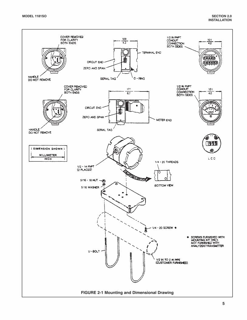
2.2.2 Transmitter Installation. The 1181SO may bemounted on a flat surface or on a 2-inch pipe by meansof a pipe mounting bracket (PN 2002577). There aretwo threaded mounting holes located in the bottom ofthe 1181SO housing (see Figure 2-1).
2.3 SENSOR INSTALLATION. Refer to the appropri-ate Model Hx438 or Gx448 Sensor Instruction Manualfor proper installation. Do not install the sensor until thecalibration procedure is performed.
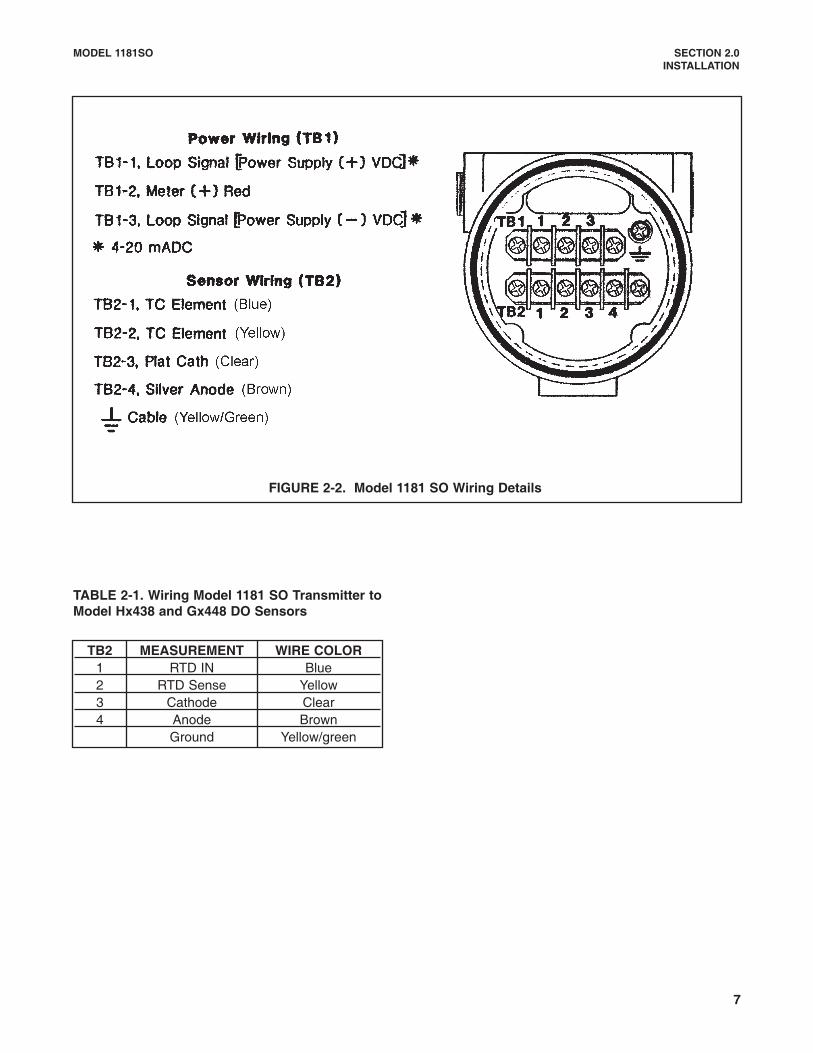
2.4 ELECTRICAL INSTALLATION.2.4.1 Transmitter. Refer to Figure 2-2 for the wiringdetails of the 1181SO. See Section 1.2 for the electri-cal specifications.
The transmitter is equipped with two 1/2-inch conduitopenings, one on each side of the housing. One is forpower supply and signal wiring and the other is forsensor input (see Figure 2-1).
To access the terminal boards, remove the cover onthe terminal (or meter) end of the transmitter, thenremove the meter assembly from the transmitter hous-ing. The upper terminal block (TB1) is for the powersupply and meter connections. The lower terminalblock (TB2) is for the sensor input connections.
2.4.2 Wiring Procedure.Connect the power wiring as follows:
+ VDC Power Supply to TB1-1- VDC Power Supply to TB1-3
Connect the meter wiring as follows:+ Meter Terminal to TB1-2- Meter Terminal to TB1-3
Signal Wiring (4-20 mA DC output) is the same as forpower supply wiring:
+ Loop Signal to TB1-1- Loop Signal to TB1-3
NOTE:It is recommended that the power sup-ply/signal wiring be twisted pairsenclosed in a shielded cable. Thecable should be grounded in only oneplace preferably at the instrument.The instrument case shall be ground-ed.Signal or sensor wiring should neverbe run in the same conduit or opentray with AC power line, alarm, controlor output signal cables. Keep signal orsensor wiring at least 12 inches fromheavy electrical equipment. (Note con-tinued on page 6).
MODEL 1181SO SECTION 2.0INSTALLATION
5
FIGURE 2-1 Mounting and Dimensional Drawing

MODEL 1181SO SECTION 2.0INSTALLATION
NOTE CONT.
For maximum EMI/RFI protection the outputcable should be shielded and enclosed in anearth grounded, rigid metal conduit. Connectthe output cable’s outer shield to the transmit-ter’s earth ground via the ground terminal nextto TB-1.
The sensor cable should also be shielded.Connect the sensor cable’s outer shield to thetransmitter’s earth ground via the ground ter-minal next to TB1. If the sensor cable’s outershield is braided an appropriate metal cablegland fitting may be used to connect the braidto earth ground via the instrument case.
A new addition to the suite of tests done toensure CE compliance is IEC 1000-4-5. This isa surge immunity test that simulates overvolt-ages due to switching and lightning transients.
In order to meet the requirements of this test,additional protection must be added to theinstrument in the form of a Transient Protectorsuch as the Rosemount Model 470D. This is a3½-inch tube with ½-inch MNPT threads onboth ends. Inside the tube are gas dischargeand zener diode devices to limit surges to thetransmitter from the current loop. No addition-al protection is needed on the sensor connec-tions.
2.4.3 Sensor.
Carefully insert the spade lug terminated sensor cablethrough the conduit opening. Connect the sensor toTB2 as shown in Figure 2-2.
NOTE:
Conduit connections on the transmitter hous-ing must be sealed or plugged (with a sealingcompound) to avoid accumulation of moisturein the housing.
Please refer to the sensor's instruction manualfor additional information on its wiring.
IMPORTANT:
Make sure all wiring connections are correctand tight. Do not apply power to the 1181SO atthis time.
For wiring to the Model Hx438 and Model Gx448Dissolved Oxygen Sensors, please see Table 2-1.
2.5 HAZARDOUS LOCATIONS-EXPLOSION PROOFINSTALLATION. In order to maintain the explosionproof rating for installed transmitter, the following condi-tions must be met:
1. The transmitter enclosure covers must be on handtight, and the threads must not be damaged
NOTE:These covers seat on O-rings whichserve to provide a dust proof enclosurefor Class II and Class III installations.
2. Conduit must be properly installed with appropriateseals.
3. If one of the conduit connections on the housing isnot used, it must be closed with a threaded metalplug with at least five threads engaged.
4. The serial tag cover on the external ZERO andSPAN adjustments must be in place.
5. FM Explosion proof installation must be in accor-dance with Drawing Number 1400155 (See Figure2-3).
6. Due to the nature of the measurement, sensorscannot be designed to meet explosion proof certifi-cation. If the sensors must be installed in haz-ardous area locations, Rosemount Analytical Inc.recommends that an intrinsically safe system beinstalled.
2.6 HAZARDOUS LOCATIONS-INTRINSICALLYSAFE INSTALLATION. To secure and maintain intrinsi-cally safe installations for the appropriate approvalagency, the following conditions must be met:
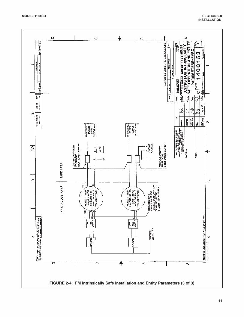
1. Code 67 must be specified when ordering F.M. units.Installation must be in accordance with Drawing Number1400153 (Figure 2-4 Entity Approved Installation).
2. Code 69 must be specified when ordering CSA units andinstallation must be performed in accordance withDrawing Number 1400157 (Figure 2-5).
3. Code 73 must be specified when ordering CENELECunits and installation must be performed in accordancewith Drawing Number 1400143 (Figure 2-6).
6
MODEL 1181SO SECTION 2.0INSTALLATION
7
TABLE 2-1. Wiring Model 1181 SO Transmitter toModel Hx438 and Gx448 DO Sensors
FIGURE 2-2. Model 1181 SO Wiring Details
TB2 MEASUREMENT WIRE COLOR1 RTD IN Blue2 RTD Sense Yellow3 Cathode Clear4 Anode Brown
Ground Yellow/green

MODEL 1181SO SECTION 2.0INSTALLATION
8
FIGURE 2-3. FM Explosion-Proof Installation
DW
G.
NO
.R
EV.
1400155
C

MODEL 1181SO SECTION 2.0INSTALLATION
9
FIGURE 2-4. FM Intrinsically Safe Installation and Entity Parameters (1 of 3) [continued on following page]

MODEL 1181SO SECTION 2.0INSTALLATION
10
FIGURE 2-4. FM Intrinsically Safe Installation and Entity Parameters (2 of 3) [continued on following page]
MODEL 1181SO SECTION 2.0INSTALLATION
11
FIGURE 2-4. FM Intrinsically Safe Installation and Entity Parameters (3 of 3)

MODEL 1181SO SECTION 2.0INSTALLATION
12
FIGURE 2-5. CSA Intrinsically Safe Installation

MODEL 1181SO SECTION 2.0INSTALLATION
13
FIGURE 2-6. CENELEC Intrinsically Safe Installation (1 of 3) [continued on following page]
DW
G.
NO
.R
EV.
1400143
C

MODEL 1181SO SECTION 2.0INSTALLATION
14
FIGURE 2-6. CENELEC Intrinsically Safe Installation (2 of 3) [continued on following page]
DW
G.
NO
.R
EV.
1400143
C

15
MODEL 1181SO SECTION 2.0INSTALLATION
FIGURE 2-6. CENELEC Intrinsically Safe Installation (3 of 3)
DW
G.
NO
.R
EV.
1400143
C

MODEL 1181SO SECTION 3.0CONFIGURATION, START UP, AND CALIBRATION
SECTION 3.0CONFIGURATION, START UP AND CALIBRATION
powered up with the range switch set to Stand-by evenwhen not in use. Setting the range switch to Stand-byallows the sensor to be polarized while preparing forcalibration or while undergoing routine maintenance.This also prevents the sensor from being oxygen sat-urated. Sensor life will not be shortened under theseconditions because only a very small current flowsthrough the sensor. If for any reason the sensor has tobe disconnected (or the transmitter switched off) thesensor will have to be repolarized before it can beready for further operation.
3.3.1 Sensor Current. During the polarization period,the sensor (electrode) current will fall off even in oxy-gen free solutions. For this reason, an excessive zerocurrent (sensor current at 0 mm Hg oxygen) may indi-cate an incomplete polarization. Though the zero cur-rent of the sensor is usually negligibly small andalmost identical with the 1181SO's zero point, the sen-sor zero point should be checked periodically since anexcessive zero current may indicate a failing sensor(refer to the Model Hx438 or Gx448 Sensor Manual foradditional information on sensor zero).
3.3.2 Zero Point Calibration. Prepare the calibrationset up as shown in Figure 3-1 (refer to the sensor'sinstruction manual for additional information on zeropoint calibration.A. For low oxygen concentrations, or when the sensorzero current exceeds 2-5% of full scale.
1. Follow Start up procedure (Section 3.3). Allowthree (3) hours for polarization period if the trans-mitter was just powered up.
2. Set the range dip switches in their proper posi-tions for the desired range.
3. Place the sensor in a freshly prepared, bubblefree, 2% bisulphite solution, or expose the sensorin pure nitrogen gas. Let it stabilize.
4. When the reading is stable, adjust the externalzero pot to get a reading of 4 mA DC on M1.
3.1 GENERAL. This section provides the configura-tion, start up and calibration procedures for the Model1181SO Two-Wire Transmitter. The transmitter is usedin conjunction with the Rosemount Model Hx438 orGx448 Steam Sterilizable Dissolved Oxygen Sensorand the Rosemount Model 515 Power Supply. (Referto Section 4.3 for 1181SO's Description of Controls.)
3.2 CONFIGURATION
3.2.1 1181SO with Analog Meter (Option-03). Thedesired range may be selected by placing the RangeDip Switches in their proper positions. The analogmeter has a scale with three different ranges of 0-100mm Hg, 0-200 mm Hg, and 0-800 mm Hg. The analogmeter is proportionally activated by the transmitter's 4-20 mA output. The oxygen concentration is obtainedby reading the position of the needle on the pre-select-ed range on the meter face.
NOTE:A special meter face may be orderedto read in your desired scale units.Consult the factory.
3.2.2 1181SO with LCD (Option-06). The LCD Meterhas its own zero and span adjustment pots for furthercalibration. The 1181SO with LCD meter (Option-06)may be configured to read directly in mm Hg, mg/l orppm, % O2 or % saturation (see Table 3-1) for variousranges and units and their corresponding range dipswitch positions).
3.3 START UP. Start up the 1181SO by performing thefollowing procedures:1. Make sure the 1181SO is properly wired. (refer to
Figure 2-2)2. Power up the 1181SO.3. Set the range dip switches to "STBY" (Stand-by).
When the transmitter is powered up, a polarizationvoltage is applied between the anode and the cathode.The sensor (electrode) current is initially very high thenit falls off quickly and settles down to a steady stateafter a few hours. Since this polarization period is rela-tively long, it is recommended to leave the 1181SO
16

MODEL 1181SO SECTION 3.0CONFIGURATION, START UP CALIBRATION
17
5. If you have an analog meter (Option - 03), the indi-cating needle should be right at 0.The needle maybe set to 0 by adjusting the screw at the bottomfront of the meter.If you have an LCD digital meter (Option - 06), a 0reading may be obtained by adjusting the LCDmeter's own zero pot.
6. Proceed to Span Calibration, Section 3.4.
B. If the sensor zero current is within the desiredmeasuring accuracy (below 2% of full scale) orsensor current is near zero at 0 mm Hg:
1. Perform Steps 1-3 of Section 3.3.2, A.
2. Place the sensor in air or in an agitated, bubblefree water (see Figure 3-2). Let it stabilize.
3. When the reading is stable, disconnect the cath-ode sensor lead (White) from TB 2-3.
4. Perform Steps 4 and 5 of Section 3.3.2, A.
5. Reconnect the cathode sensor lead (White) to TB2-3.
6. Proceed to Span Calibration, Section 3.4.
FIGURE 3-1. Calibration Set Up

MODEL 1181SO SECTION 3.0CONFIGURATION, START UP, CALIBRATION
3.4 SPAN CALIBRATION.
3.4.1 General. The 1181SO may be span calibratedusing fresh water or ambient air. The calculated spancalibration value should be at least 70% of the maxi-mum scale reading to ensure optimum accuracy.
Table 3-1 shows the different ranges and units withtheir corresponding range dip switch positions. (SeeFigure 4-2.)
4 mA DC output corresponds to your zero or minimumreading on the scale selected and 20 mA DC outputcorresponds to the maximum reading on the scaleselected.
Calibration in a fermentor may be performed only aftersterilization because sterilization may alter the sen-sor's (electrode's) span (slope). This alteration may becomparatively large, particularly when a membranecartridge is used for the first time. After cooling, the fer-mentor is aerated. As soon as the reading is stable, thedesired calibration point is set.
In large-size aerated fermentors the sensor should becalibrated in place after sterilization. Calibration shouldbe carried out under flow, aeration and pressure condi-tions approximating as closely as possible those condi-tions expected to be encountered in measurement.During measurement, the temperature and pressure inthe fermenter should remain constant.
The O2 measuring loop should be recalibrated prior toeach fermentation. If work is performed under sterileconditions, the system must be calibrated with thesensor (electrode) in place and after sterilizationbut prior to inoculation. If the sensor is employed tomonitor a fermentation process that extends over sev-eral days (or weeks) with no possibility of changing it,the electrical zero point of the sensor should bechecked before insertion.
Please refer to the sensor manual for instructions onsensor calibration.
18
TABLE 3-1Range -vs- Dip Switch Position
(see Figure 4-2)
UNITS DESIRED RANGE DIP SWITCH POSITION(4mA -20mA) SWITCH
C1 C2 C4 C3TO USE0-100.0 mm Hg 0-100* Closed Closed Open Not0-200 mm Hg 0-200 Open Closed Used0-800 mm Hg 0-800 Closed Open
0-5.00 ppm (mg/l) 0-100* Closed Closed0-10.00 ppm (mg/l) 0-200 Open Closed0-40.0 ppm (mg/l) 0-800 Closed Open
0-15.0%O2 0-100* Closed Closed0-30.0%O2 0-200 Open Closed
0-100.0%O2 0-800 Closed Open
0-100% Saturation 0-200 Open Closed
*Note: The unit is supplied from the factory in the 0-100 range.

MODEL 1181SO SECTION 3.0CONFIGURATION, START UP, AND CALIBRATION
19
3.4.2 General Span Calibration Procedure. Makesure zero point calibration (Section 3.3.2) was proper-ly performed. Make sure the 1181SO is still poweredup (refer to Figure 3-1).
1. Expose the sensor in the calibrating medium.Allow up to 60 minutes for the reading to stabilize.
2. When the reading is stable, adjust the externalspan pot to the minimum reading (see Figure 4-2).
3. Set the coarse span adjust pot to get a mA displayon M1 to equal (see Figure 4-2):
Calibration Value
Maximum Scale Readingof Range Selected
4. Fine tune using the external span pot.
NOTE:The analog meter (Option-03) is pro-portionally activated by the 1181SO's4-20mA output.
The LCD Meter (Option - 06), on the other hand, maybe further calibrated by adjusting its own span (R4)and zero (R8) adjustment pots (see Figure 4-3).
5. For units with LCD Meter, adjust the LCD's ownspan pot to get a reading on the meter displayequal to the calibration value.
6. Recheck for zero and span until no further adjust-ment is necessary.
7. Disconnect the digital Ammeter M1. Reconnectthe power supply and the indicating meter wiringaccording to Figure 2-2. Replace the transmittercovers.
8. Install the sensor as instructed in the sensor'sinstruction manual.
3.4.3 Calibration Medium.
A. AMBIENT AIR. The 1181SO may be span calibrat-ed by exposing the sensor to ambient air. Air contains20.9% oxygen (volume % or pressure %) the calibra-tion point or value should be:
BP mm Hg x 0.209
760 mm Hg
X 16 + 4 WHERE:mA = Milliamps DC display in M1 that the 1181SOshould be adjusted to (see Steps 3 and 4, Section3.4.2).
The LCD's own span adjust pot is set to get an LCDdisplay of:(BP + Pp - Pv) 0.209 mm Hg, the partial pressure ofoxygen at a given time. (see Step 5., Section 3.4.2).
BP = Barometric Pressure in mm HgPp = Process Pressure in mm HgPv = Water Vapor Pressure in mm Hg
If the BP is given in inches Hg, convert this to mm Hgby multiplying it by a factor of 25.4.
EXAMPLE:
BP = 25.4 X 30.16 = 766 mm Hg0-200 mm Hg Range Selected:
mA output =
= 17.98 mA DC on M1 ² 174.7 mm Hg LCD Display
If 0-800 mm Hg is Selected:
(766 + 100 - 30) 0.209
800= 7.5 ma DC on M1 ² 174.7 mm Hg LCD Display
(BP + Pp -Pv) 0.209
Maximum Full Scale Readingat range selected, mm Hg
BP = 30.16 in HgPp = 100 mm HgPv = 30 mm Hg (from Table 3-2)Temp. = 29°C
X 16 + 4
(766 + 100 - 30) 0.209
200
mA Output = X 16 + 4
mA = x 16 + 4
B. CALIBRATION UNDER PRESSURE. TheBarometric Pressure (BP), temperature, and theexcess pressure (Pp), if any, in the reaction vesselmust be known to calculate the calibration value.Calibration Value = (BP + Pp - Pv) X0.209 the outputdisplay on M1 should be:

MODEL 1181SO SECTION 3.0CONFIGURATION, START UP, AND CALIBRATION
20
3.4.3 Calibration Medium (continued)Where large reaction tanks are involved, the hydrostat-ic pressure (10 m head of water corresponds to 735mm Hg) must be taken into account. In the absence ofair bubbles the hydrostatic pressure exercises negligi-ble influence on the oxygen partial pressure.
In aerated fermentors conditions are quite complex.The oxygen sensor is under substantial hydrostaticpressure and calibration in mm Hg is unsuitable. Insuch cases, the degree of saturation with atmosphericoxygen is the most suitable parameter.
C. FRESH WATER SATURATED WITH AIR. The1181SO may also be span calibrated by immersing thesensor in a beaker of agitated fresh water (see Figure3-2).
In determining oxygen concentration of solutions, theO2 content of the calibrating solution must be accu-rately known. The values applying to fresh water areknown and shown in Table 3-3. These solubilitiesneed only be adjusted to the prevailing barometricpressure, (BP).
Solubility (S) =
This calibration is reliable only if measurements areaffected in dilute aqueous solutions. In concentratedsolutions the oxygen solubility must first be determinedby a Winkler titration.
Water-vapor partial pressure in mm Hg:
Temp. Pv Temp. Pv°C mm Hg °C mm Hg
0 5 20 182 5 22 204 6 24 226 7 26 258 8 28 28
10 9 30 3212 11 32 3614 12 34 4016 14 36 4518 16 38 50
40 55
TABLE 3-2
760 mm Hg
Solubility 760 mm Hg X BP
The mA output display on M1 should be:
0.209 X BP mm Hg
Maximum Full Scale Readingat range selected, mm Hg
The LCD span should be set to read, S:
Solubility at 760 mm Hg
760
EXAMPLE:
BP mm Hg = 30.1 X 25.4 = 764.5 mm HgFrom Table 3-3 solubility at 760 mm Hg, at 20°C and0ft. elevation = 9.1 ppm.
Solubility of Oxygen,mg/l (ppm) at Various Temperatures and
Elevations in Fresh Water(Based on Sea Level Barometric Pressure of 760 mm Hg)
°C 0 1000 2000 3000 4000 5000 60000 14.6 14.1 13.6 13.2 12.7 12.3 11.82 13.8 13.3 12.9 12.4 12.0 11.6 11.24 13.1 12.7 12.2 11.9 11.4 11.0 10.66 12.4 12.0 11.6 11.2 10.8 10.4 10.18 11.8 11.4 11.0 10.6 10.3 9.9 9.6
10 11.3 10.9 10.5 10.2 9.8 9.5 9.212 10.8 10.4 10.1 9.7 9.4 9.1 8.814 10.3 9.9 9.6 9.3 9.0 8.7 8.316 9.9 9.7 9.2 8.9 8.6 8.3 8.018 9.5 9.2 8.7 8.6 8.3 8.0 7.720 9.1 8.8 8.5 8.2 7.9 7.7 7.422 8.7 8.4 8.1 7.8 7.7 7.3 7.124 8.4 8.1 7.8 7.6 7.3 7.1 6.826 8.1 7.8 7.6 7.3 7.0 6.8 6.628 7.8 7.5 7.3 7.0 6.8 6.6 6.330 7.5 7.2 7.0 6.8 6.5 6.3 6.132 7.3 7.1 6.8 6.6 6.4 6.1 5.934 7.1 6.9 6.6 6.4 6.2 6.0 5.836 6.8 6.6 6.3 6.1 5.9 5.7 5.538 6.6 6.4 6.2 5.9 5.7 5.6 5.440 6.4 6.2 6.0 5.8 5.6 5.4 5.2
TABLE 3-3
Elevation, Feet above Sea LevelTemp.
mA = X 16 + 4
S= X BP mm Hg
Temperature = 20°CElevation = 0 ft.BP = 30.1 m Hg
range selected0-200 mm Hg

MODEL 1181SO SECTION 3.0CONFIGURATION, START UP, AND CALIBRATION
21
3.4.3 Calibration Medium (continued).
0.209 (764.5)
200
Adjust LCD's span pot to S:
9.1 (764.5)
760
mA Output = X 16 + 4 = 16.78 mA
S = = 9.15 ppm (mg/l)
At this point, the LCD's span pot can also be made toread in %O2 (if desired) to:
20.9% to indicate %O2
or 100% to indicate the % saturation. (A solution satu-rated with air is defined as 100% saturated).
FIGURE 3-2. Calibration with Agitated Fresh Water

MODEL 1181SO SECTION 4.0OPERATION AND DESCRIPTION OF CONTROLS
SECTION 4.0OPERATION AND DESCRIPTION
OF CONTROLS4.1 THEORY OF OPERATION. The Model 1181SO Two-Wire Transmitter automatically and continuously meas-ures concentrations of dissolved oxygen in water or aque-ous solutions. The determination is based on the meas-urement of the electrical current developed by the ModelHx438 or Gx448 sensor in contact with the sample.
The polarographic (Clark's principle) membrane tech-nique is used for the measurement and control of dis-solved oxygen.The success of membrane electrodesstems from the isolation of the electrodes (cathode andanode) and electrolyte from the sample by means of asemi-permeable membrane. This membrane protectsthe electrodes from contamination by restricting theflow of sample to gases only, and oxygen in particular.
Within the body of the sensor are a platinum cathodeand a silver anode, electrically connected by potassi-um chloride electrolyte solution and separated from theprocess stream by the gas permeable membrane. The
transmitter lifts off approximately 10 VDC from the loopcurrent to power the electronics and, in turn, supplies aconstant 675mV DC polarizing voltage which is appliedacross the two electrodes.
Oxygen from the sample diffuses through the mem-brane and is reduced at the platinum cathode. Theresultant electrical current flow between anode andcathode is proportional to the partial pressure of oxy-gen in the sample. The chemical reactions whichaccompany this process are as follows:
Platinum cathode: O2 + 2H2O + 4e- 4OH-Silver anode: 4Ag + 4Cl- 4AgCl + 4e-
The reaction that takes place at the anode is the oxi-dation of silver to form silver chloride. This reaction isoffset at the platinum cathode by the reduction of oxy-gen molecules to hydroxyl ions. The resulting current isdirectly proportional to the dissolved oxygen content ofthe sample stream.
FIGURE 4-1. Oxygen Solubility in Fresh and Seawater of Varying Degrees of Salinity, BP = 760 mm Hg
22

MODEL 1181SO SECTION 4.0OPERATION AND DESCRIPTION OF CONTROLS
4.1.1 Basic D.O. Measurement.1. Dissolved Oxygen - The amount of gaseous oxygen,in mg/l, or ppm by weight, dissolved in a liquid (usual-ly H2O). The presence of dissolved solids affects thesolubility of oxygen in water.
2. The amount of oxygen dissolved in fresh water at100% saturation is inversely proportional to the tem-perature, and is directly proportional to the pressure.
3. At sea level and a temperature of 20°C, an oxygensaturated solution of water contains 9.2 ppm (parts permillion) of oxygen. The figure of 9.2 ppm representsthe weight of oxygen with respect to the weight ofwater.
4. A polarographic oxygen sensor measures oxygen inair as well as in water. In fact, most sensors are air cal-ibrated prior to water measurements.
5. The mineral content of water solution will also alterthe amount of dissolved oxygen. For example, saltwater in the ocean at 20°C contains only 7.4 ppm ofdissolved oxygen compared to fresh water which con-tains 9.2 ppm. This difference may account for the factthat some fish cannot survive when moved from freshto salt water and vice versa.
4.2 MEASUREMENT VARIABLES. Variables thatinfluence the dissolved oxygen measurement includebarometric pressure, relative humidity, sample temper-ature, interfering gases and composition of the liquidmedium.
4.2.1 Barometric Pressure. Rate of oxygen diffusionthrough the sensor membrane, and therefore the sen-sor response, is linear with respect to oxygen partialpressure (assuming constant sample temperature).
At the normal sea-level barometric pressure of 760 mmHg, the oxygen partial pressure of dry air is 160 mmHg. As atmospheric pressure deviates from the stan-dard value, the oxygen partial pressure varies propor-tionally. Accordingly, the solubility of oxygen in watervaries in proportion to the change in the partial pres-sure of oxygen in air. Barometric pressure is thereforea significant factor in instrument calibration.
4.2.2 Relative Humidity. In calibration for dissolvedoxygen measurement, one method is to expose thesensor to a gaseous sample, typically dry air, of accu-rately known oxygen content. The known gaseous oxy-gen concentration value is then related to a correspon-ding dissolved oxygen value.
Since dry air contains 20.95% oxygen by volume,regardless of the barometric pressure, oxygen can beshown to be directly proportional to the total baromet-ric pressure, according to Dalton's law of partial pres-sures. Thus for dry air, if the total barometric pressureis known, the partial pressure of oxygen can be com-puted. However, this procedure is valid only for dry airconditions. Humid air has the effect of reducing thepartial pressure of oxygen and the other gases in theair without affecting the total barometric pressure.
Thus, for constant barometric pressure, if the humidityin the air is other than zero, the partial pressure of oxy-gen is less than the value for dry air. For most meas-urements taken below 80°F (26.7°C), the effect ofwater vapor may be ignored.
To determine the partial pressure of oxygen in air atvarious levels of humidity and barometric pressure, thepartial pressure of water is subtracted from the totalbarometric pressure and the difference is multiplied by20.95%.
EXAMPLE:If the Barometric pressure = 740 mm Hgand the Partial Pressure H2O = 20 mm Hgthen the Partial pressure O2= [740 - 20] x 0.2095 mm Hg= 151 mm Hg
4.2.3 Sample Temperature. The temperature of thesample affects sensor response in two ways:
1. Oxygen Diffusion Rate -- The rate of oxygen diffu-sion through the sensor membrane varies with temper-ature at a coefficient of about +3% per degree Celsius,causing a corresponding change in sensor current.
2. Oxygen Solubility -- In an oxygen-saturated liquid,partial pressure of dissolved oxygen is equal to thepartial pressure of oxygen in the atmosphere above liq-uid. This relationship holds true regardless of the oxy-gen concentration. As sample temperature increases,oxygen partial pressure remains unchanged (except asinfluenced by vapor pressure of the liquid); however,the dissolved oxygen concentration is reduced.
23

24
MODEL 1181SO SECTION 4.0OPERATION AND DESCRIPTION OF CONTROLS
4.2.3 Sample Temperature (continued)To compensate for temperature, the Model 1181SOuses the thermistor incorporated in the Model Hx438 orGx448 sensor. As the sample temperature changes,the thermistor resistance also changes affecting thesignal gain of the transmitter. The result is a tempera-ture corrected dissolved oxygen reading.
4.2.4 Interfering Gases. Gases that are reduced oroxidized at about 0.675 VDC, and thus contribute tosensor current, may cause a readout error. Only a fewgases have this characteristic. Common gases thatshould be avoided include SO2, Cl2 and oxides of nitro-gen. Low-level concentrations of hydrogen-sulfide tendto contaminate the sensor, but do not seriously affectdissolved oxygen measurement. If contaminated, thesensor must be rejuvenated.
4.2.5 Composition of the Liquid Medium. A signifi-cant change in the composition of the solution maychange the solubility of oxygen. If the solvent is water,the addition or presence of any water soluble compo-nents, such as sodium chloride, may change the dis-solved oxygen concentration.
In an open equilibrium system, where gas of constantoxygen partial pressure is in direct contact with a saltsolution, the solubility of oxygen decreases as salinityincreases.
4.3 DESCRIPTION OF CONTROLS. (Refer to Figure4-2 for location of control or adjustment pots, etc.)
4.3.1 Range Selector Switch. There are four rangedip switches: C1, C2, C3 and C4. The desired range ofthe 1181SO may be selected by "closing" or "opening"the switches according to the matrix shown on the PCBcover in Figure 4-2.
NOTE:C3 is not used in any range.
EXAMPLE: If a range of 0-200 mm Hg is desired, C2is in closed position, while Cl and C4 are in open posi-tion (see Table 3-1).
If your desired reading is in mg/l or ppm of dissolvedoxygen:
For 0-5.00 mg/l (ppm) use 0-100 mm Hgrange dip switch setting
For 0-10.00 mg/l (ppm) use 0-200 mm Hgrange dip switch setting
For 0-40.0 mg/l (ppm) use 0-800 mm Hgrange dip switch setting
If your desired reading is % saturation (a solution sat-urated with air is said to be 100% saturated): Use 0-200 mm Hg range dip switch setting.
If your desired reading is % oxygen:For 0-15.0% O2 use 0-100 mm Hg
range dip switch settingFor 0-30.0% O2 use 0-200 mm Hg
range dip switch settingFor 0-100.0% O2 use 0-800 mm Hg
range dip switch setting
In the "STBY" (Stand By) position, Cl, C2 and C4 arein closed position. The "STBY" position is used to keepthe sensor polarized (when the 1181SO is poweredup). This saves considerable repolarization time after aperiodic maintenance in the process, troubleshootingor temporary shut down.
4.3.2 Coarse Span Adjust. A printed circuit boardmounted potentiometer (280° turn) used for coarseadjustment of the operating range for the 1181 trans-mitter (refer to Figure 4-2).
4.3.3 External Zero Adjust. A 20-turn potentiometerfor fine tuning the low end current output value withrespect to the low end of the measurement rangeselected by the Range Selector Dip Switches (refer toFigure 4-2).
4.3.4 External Span Adjust. A 20-turn potentiometerfor fine tuning the full scale current output with respectto the full scale value of the measurement rangeselected by the Range Selector Dip Switches (refer toFigure 4-2).
4.3.5 LCD Zero and Span. Printed circuit boardmounted potentiometers for adjustment of the LCD dis-play. The display can be adjusted for any value from 0to 1999 to match the transmitter's 0-20 mA DC output(refer to Figure 4-3 for the location).
4.3.6 LCD Decimal Point Switch. Dip switches 1, 2and 3 for the selection of the decimal point in the digi-tal display is located about 5 o'clock of the meter face(refer to Figure 4-3). A closed position turns on thedecimal point while an open position turns off the dec-imal point. When all the dip switches are off, the deci-mal point is assumed to be after the rightmost digit.

MODEL 1181SO SECTION 4.0OPERATION AND DESCRIPTION OF CONTROLS
FIGURE 4-2. Location of Controls
25
PCB COVER
RANGE MATRIX

26
MODEL 1181SO SECTION 4.0OPERATION AND DESCRIPTION OF CONTROLS
TABLE 4-1LCD Decimal Point Set Up
Ranges: 0-100 mm Hg 0-200 mm Hg 0-800 mm HgUnits
mm Hg 0-100.0 0-200 0-800
mg/l (ppm) 0-5.00 0-10.00 0-40.0
%O2 0-15.0 0-30.0 0-100.0
% Saturation - 0-100.0 -
FIGURE 4-3. 1181SO LCD Meter Option
4.4. Converting an 1181SO with an existing blind oranalog indication to an LCD (digital) unit. (Option06). See Section 5.2 for disassembly.
The 1181SO with an Option -03 (analog display) orOption -02 (blind) may be retrofitted or modified easily toan LCD (digital) unit. The jumper is simply moved fromthe W5 position to the W6 position (see Figure 4-3).
After moving the jumper to W6 position, the 1181SOwill only be compatible with an LCD meter (refer toSection 2.4.2 for the proper wiring of the LCD meter tothe 1181SO).

MODEL 1181SO SECTION 5.0DIAGNOSTICS AND MAINTENANCE
SECTION 5.0DIAGNOSTICS AND MAINTENANCE
5.1 GENERAL. The 1181SO was designed to nearlyeliminate the need for frequent or routine maintenance.
Most routine maintenance involves the sensor. Sensormaintenance consists of periodic recharging andcleaning, or rejuvenating the sensor cathode. Theusual indication that the sensor requires rejuvenationand recharging is that, during calibration the correctupscale reading is unobtainable by adjustment of theEXTERNAL SPAN. Normally, the inability to calibrate ispreceded by a gradual, day-to-day reduction in sensoroutput, with a resultant lower instrument indication.The rate of reduction increases with the increase ininternal resistance of the sensor. (Please refer to theappropriate section in the Model Hx438 or Gx448Sensor Instruction Manual for Sensor Diagnostics andMaintenance).
5.2 DISASSEMBLY PROCEDURE. Disconnect thepower to the transmitter prior to disassembly (refer toFigure 6-1 for item numbers also see Figure 2-2).
1. Remove covers (1) and (10) from housing (3).Save O-rings (2); discard if damaged.
2. Loosen screws retaining the serial label, and thenrotate to gain access to the span and zero pots.
3. Align the span and zero adjusting screws (4), sothe slots are horizontal, pointing end cap to endcap. Refer to Figure 4-2.
4. In the circuit side of the housing (3) remove the cir-cuit board retaining screws, washers and matrixcover (9). The matrix cover is secured to screwsby nylon split washers. Remove the screws inequal increments, so the matrix cover is not dam-aged.
5. Pull straight out on the signal conditioning boardassembly (8) to remove circuit boards from hous-ing (3).
6. To separate the individual boards, remove theretaining screw located on the terminal side of thetransmitter board (6).
7. Remove each printed circuit board assembly bypulling straight out from their respective connec-tors.
5.3 REASSEMBLY PROCEDURE (see Figures 6-1, 6-5 and 2-2).
1. Assemble the circuit board assemblies (6,7,8) byfirst aligning the connectors with the respectivepins, and then pushing straight in. Install screwwhich holds circuit board assemblies together.
2. Align the zero and span adjusting screws (4) onthe housing (3) to the horizontal position, slotspointing end cap to end cap (see Figure 4-2).
3. Align the zero and span potentiometers located onthe power circuit board (7) to the horizontal posi-tion, with blades perpendicular to PCB's (6) and(7).
4. Place the circuit board assemblies (6, 7, 8) intohousing by first aligning the connector pins withthe terminal receptacles in the base of the housing(3) and then pushing straight in on the signal con-ditioning board (8).
5. Install the matrix cover (9) and secure with screwsand washers.
6. Inspect the thread connections on housing (3) tomake sure five undamaged threads will fullyengage.
7. Replace O-rings (2) on housing (3). Use new O-rings if the old ones were damaged.
8. Install covers (1,10) on transmitter housing (3).
9. Apply power to the transmitter and perform theappropriate calibration procedure if necessary.
27
28
MODEL 1181SO SECTION 5.0DIAGNOSTICS AND MAINTENANCE
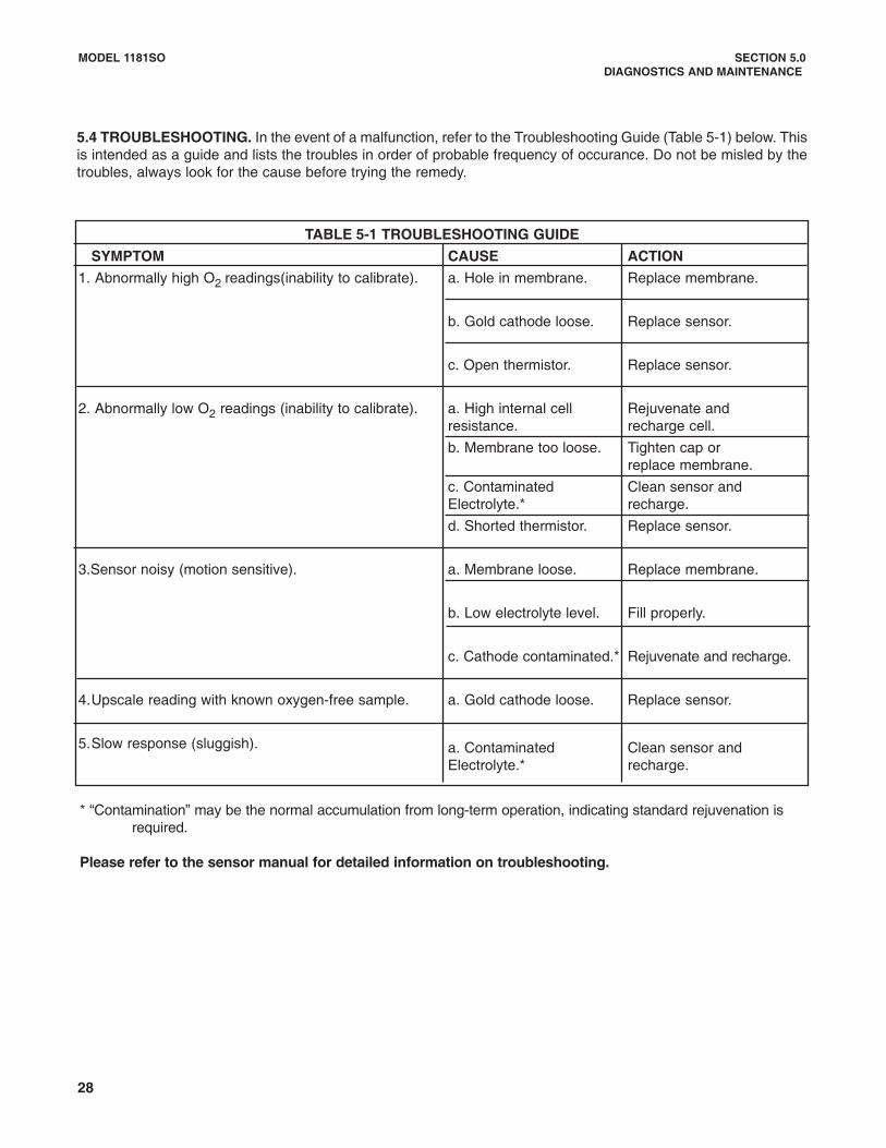
5.4 TROUBLESHOOTING. In the event of a malfunction, refer to the Troubleshooting Guide (Table 5-1) below. Thisis intended as a guide and lists the troubles in order of probable frequency of occurance. Do not be misled by thetroubles, always look for the cause before trying the remedy.
TABLE 5-1 TROUBLESHOOTING GUIDE
SYMPTOM CAUSE ACTION
1. Abnormally high O2 readings(inability to calibrate). a. Hole in membrane. Replace membrane.
b. Gold cathode loose. Replace sensor.
c. Open thermistor. Replace sensor.
2. Abnormally low O2 readings (inability to calibrate). a. High internal cell Rejuvenate andresistance. recharge cell.
b. Membrane too loose. Tighten cap or replace membrane.
c. Contaminated Clean sensor and Electrolyte.* recharge.
d. Shorted thermistor. Replace sensor.
3.Sensor noisy (motion sensitive). a. Membrane loose. Replace membrane.
b. Low electrolyte level. Fill properly.
c. Cathode contaminated.* Rejuvenate and recharge.
4.Upscale reading with known oxygen-free sample. a. Gold cathode loose. Replace sensor.
5.Slow response (sluggish). a. Contaminated Clean sensor and Electrolyte.* recharge.
* “Contamination” may be the normal accumulation from long-term operation, indicating standard rejuvenation is required.
Please refer to the sensor manual for detailed information on troubleshooting.

MODEL 1181SO SECTION 5.0DIAGNOSTICS AND MAINTENANCE
FIGURE 5-1. 1181SO Operation Check Set-Up
5.5 1181SO OPERATION CHECK. When the 1181SOis suspected to be malfunctioning, the operation maybe checked by the set-up shown in Figure 5-1.
5.5.1 Equipment needed:1181SO TransmitterD1, Meter Display (Analog with Option 03 or
LCD with Option 06)Model 515 Power SupplyM1, Digital AmmeterResistor, 23 K�Resistance Decade Box, 0-30 M�
5.5.2 1181 Operation Check-Up Procedure:1. Prepare the set-up as shown in Figure 5.1.
2. Enter: 21.0 Megohms for 0-100 mm Hg range.10.6 Megohms for 0-200 mm Hg range.2.68 Megohms for 0-800 mm Hg range.
3. Set the Range Dip Switches in your desired range.
4. Power up the 1181SO.
5. Disconnect Terminal 3 of TB2.
6. Adjust the External Zero pot to get a reading of4mA DC on M1.
NOTEThe LCD's zero pot may be adjusted toget a zero reading on M1, if desired.
7. Reconnect TB2-3. Allow M1 to stabilize.
8. Adjust the External Span pot to get a minimum mAreading on M1.
9. Adjust the Course Span pot to get a reading of20mA DC on M1.
NOTEIf the 1181SO is functioning properly,the 4 and 20mA DC output should beobtained without any difficulties. TheLCD's span pot may be adjusted todisplay the maximum reading in therange selected, if desired. The1181SO must be recalibrated beforeputting it back in service.
10. Fine tune with the External Span pot if necessary.
29

30
MODEL 1181SO SECTION 6.0SPARE PARTS
SECTION 6.0SPARE PARTS
6.1 SPARE PARTS. Parts List for Figure 6-1.
ITEM PART NUMBER DESCRIPTION QTY1 3002425 Cover (for Blind Model) 2
Cover PCB End 12 2002604 O-Ring Kit, consists of: 1
9550136 O-Ring 123 2002528 Housing (Includes #4 below) 1
3A 23563-00 Housing for Code-73 (includes #4 below) 14 2002598 Adjustment Screw, consists of: 1
9160299 Retaining Ring 49550137 O-Ring 23002422 Screw, Adjustment Zero/Span 2
5 2002605 O-Ring Kit, consists of: 19550137 O-Ring 12
6 22919-00 Transmitter PCB (Blind/Analog) 122919-01 Transmitter PCB (LCD RTO) 1
7 22796-00 Power PCB 18 22909-00 Transducer PCB 19 22709-02 Matrix Cover Kit, consists of: 1
32825-00 Cover, Matrix 19600620 Screw (Short) 19600628 Screw (Long) 19910404 Washer, Nylon 29910600 Washer, Flat 29910610 Washer, Lock 2
10 2002518 Meter Cover Kit, consists of: 13002429 Housing 19550135 O-Ring 13002421 Window 132491-00 Ring, Retainer 1
11 2002603 O-Ring Kit, consists of: 19550135 O-Ring 12
12 2002600 Window Kit, consists of: 19550135 O-Ring 13002421 Window 1
13 23122-00 Meter, LCD (Code 06) Shown 114 2002599 Analog Meter Sleeve Kit, consists of: 1
3002433 Sleeve Meter, Analog 19731004 Screw, Set (Short) 49730816 Screw, Set (Long) 19560185 Nut, Hex 123123-00 Digital Meter Retrofit Kit, consists of: 123122-00 Spare LCD Meter Code 06 132822-00 Sleeve for LCD 1
15 23110-04 Plug-In Analog Meter Retrofit Kit, consists of: 116 9170170 Analog Meter, Plug-In (Code 03) 117 32955-00 Mounting Plate 118 9600606 Mounting Plate Screws 219 32996-00 Insulator 120 32961-00 Terminal Plug-In Adaptor Screws 221 32997-00 Retainer Clip 1

Figure 6-1. Model 1181SO Parts Breakdown
MODEL 1181SO SECTION 6.0SPARE PARTS
31

32
MODEL 1181SO SECTION 6.0SPARE PARTS
Figure 6-2. 1180SO Transmitter PCB
Figure 6-3. 1180SO Transducer PCB
P/N 22909-00
P/N 2219-00 Shown (Blind and Analog units)P/N 2219-01 (LCD units)

MODEL 1181SO SECTION 6.0SPARE PARTS
Figure 6-4. 1181SO Power Supply PCB
Figure 6-5. 1181SO PCB Stack
P/N 22796-00
33

34
MODEL 1181SO SECTION 7.0RETURN OF MATERIAL
SECTION 7.0RETURN OF MATERIAL
7.1 GENERAL. To expedite the repair and return ofinstruments, proper communication between the cus-tomer and the factory is important. Before returning aproduct for repair, call 1-949-757-8500 for a ReturnMaterials Authorization (RMA) number.
7.2 WARRANTY REPAIR.
The following is the procedure for returning instru-ments still under warranty:
1. Call Rosemount Analytical for authorization.
2. To verify warranty, supply the factory sales ordernumber or the original purchase order number. Inthe case of individual parts or sub-assemblies, theserial number on the unit must be supplied.
3. Carefully package the materials and enclose your“Letter of Transmittal” (see Warranty). If possible,pack the materials in the same manner as theywere received.
4. Send the package prepaid to:
Rosemount Analytical Inc., Uniloc DivisionUniloc Division2400 Barranca ParkwayIrvine, CA 92606
Attn: Factory Repair
RMA No. ____________
Mark the package: Returned for Repair
Model No. ____
7.3 NON-WARRANTY REPAIR.
The following is the procedure for returning for repairinstruments that are no longer under warranty:
1. Call Rosemount Analytical for authorization.
2. Supply the purchase order number, and make sureto provide the name and telephone number of theindividual to be contacted should additional infor-mation be needed.
3. Do Steps 3 and 4 of Section 7.2.
NOTEConsult the factory for additional informa-tion regarding service or repair.

WARRANTYSeller warrants that the firmware will execute the programming instructions provided by Seller, and that the Goods manufacturedor Services provided by Seller will be free from defects in materials or workmanship under normal use and care until the expira-tion of the applicable warranty period. Goods are warranted for twelve (12) months from the date of initial installation or eighteen(18) months from the date of shipment by Seller, whichever period expires first. Consumables, such as glass electrodes,membranes, liquid junctions, electrolyte, o-rings, catalytic beads, etc., and Services are warranted for a period of 90days from the date of shipment or provision. Products purchased by Seller from a third party for resale to Buyer ("Resale Products") shall carry only the warranty extended bythe original manufacturer. Buyer agrees that Seller has no liability for Resale Products beyond making a reasonable commercialeffort to arrange for procurement and shipping of the Resale Products. If Buyer discovers any warranty defects and notifies Seller thereof in writing during the applicable warranty period, Seller shall, atits option, promptly correct any errors that are found by Seller in the firmware or Services, or repair or replace F.O.B. point of man-ufacture that portion of the Goods or firmware found by Seller to be defective, or refund the purchase price of the defective por-tion of the Goods/Services. All replacements or repairs necessitated by inadequate maintenance, normal wear and usage, unsuitable power sources, unsuit-able environmental conditions, accident, misuse, improper installation, modification, repair, storage or handling, or any othercause not the fault of Seller are not covered by this limited warranty, and shall be at Buyer's expense. Seller shall not be obligat-ed to pay any costs or charges incurred by Buyer or any other party except as may be agreed upon in writing in advance by anauthorized Seller representative. All costs of dismantling, reinstallation and freight and the time and expenses of Seller's person-nel for site travel and diagnosis under this warranty clause shall be borne by Buyer unless accepted in writing by Seller. Goods repaired and parts replaced during the warranty period shall be in warranty for the remainder of the original warranty peri-od or ninety (90) days, whichever is longer. This limited warranty is the only warranty made by Seller and can be amended onlyin a writing signed by an authorized representative of Seller. Except as otherwise expressly provided in the Agreement, THEREARE NO REPRESENTATIONS OR WARRANTIES OF ANY KIND, EXPRESS OR IMPLIED, AS TO MERCHANTABILITY, FIT-NESS FOR PARTICULAR PURPOSE, OR ANY OTHER MATTER WITH RESPECT TO ANY OF THE GOODS OR SERVICES.
RETURN OF MATERIAL
Material returned for repair, whether in or out of warranty, should be shipped prepaid to:
Emerson Process ManagementLiquid Division
2400 Barranca ParkwayIrvine, CA 92606
The shipping container should be marked:Return for RepairModel _______________________________
The returned material should be accompanied by a letter of transmittal which should include the following information (make acopy of the "Return of Materials Request" found on the last page of the Manual and provide the following thereon):
1. Location type of service, and length of time of service of the device.2. Description of the faulty operation of the device and the circumstances of the failure.3. Name and telephone number of the person to contact if there are questions about the returned material.4. Statement as to whether warranty or non-warranty service is requested.5. Complete shipping instructions for return of the material.
Adherence to these procedures will expedite handling of the returned material and will prevent unnecessary additional chargesfor inspection and testing to determine the problem with the device.
If the material is returned for out-of-warranty repairs, a purchase order for repairs should be enclosed.

Credit Cards for U.S. Purchases Only.
The right people,the right answers,right now.
ON-LINE ORDERING NOW AVAILABLE ON OUR WEB SITEhttp://www.raihome.com
Emerson Process ManagementLiquid Division2400 Barranca ParkwayIrvine, CA 92606 USATel: (949) 757-8500Fax: (949) 474-7250
http://www.raihome.com
© Rosemount Analytical Inc. 2003