displayobjects: prototyping functional physical interfaces ... · extends illuminating clay by...
TRANSCRIPT

DisplayObjects: Prototyping Functional Physical Interfaces on 3D Styrofoam, Paper or Cardboard Models
Eric Akaoka, Tim Ginn and Roel Vertegaal Human Media Lab Queen’s University
Kingston, ON K7L 3N6 Canada
ABSTRACT This paper introduces DisplayObjects, a rapid prototyping workbench that allows functional interfaces to be projected onto real 3D physical prototypes. DisplayObjects uses a Vicon motion capture system to track the location of physical models. 3D software renditions of the 3D physical model are then texture-mapped with interactive behavior and projected back onto the physical model to allow real-time interactions with the object. We discuss the implementation of the system, as well as a selection of one and two-handed interaction techniques for DisplayObjects. We conclude with a design case that comments on some of the early design experiences with the system.
Author Keywords Early Prototyping, Physical User Interfaces, Augmented Reality, Organic User Interfaces.
ACM Classification Keywords H5.m. Information interfaces and presentation (e.g., HCI): Miscellaneous.
General Terms Human Factors.
INTRODUCTION Physical mockups have always played an important role in the early conceptual stages of design. Physical mockups are particularly important when designing mobile appliances such as cell phones or mp3 players. This is because physical mockups are often the only way to examine the physical look and feel, such as the dimensions and ergonomic fit of a device at an early stage of design. Figure 1 shows an example: an early Styrofoam mockup of the first Apple iPod. Due to the limitations of the medium, however, this first iPod would not have had full functionality embedded in its hardware prototype. Instead, physical prototypes in early
design phases are typically passive vehicles. Users are either provided with a Wizard of Oz style simulation during early evaluations, or a graphical computer user interface that provides simulations of the final functionality of the device on a computer. In this paper, we argue that one of the problems with this approach is that early user experiences remain disjoint: users experience the functionality of a device without being fully able to fuse their haptic and visual perceptions of the interface. According to Hudson and Mankoff [9], this means designers are often constrained to either creating prototypes that look like the final product (physical mockups), or work like the final product (on-screen software). To alleviate this problem, they proposed augmenting physical mockups with sensors that capture the interaction styles of physical inputs such as button presses in physical cardboard and Styrofoam prototypes [12]. While workbenches like d.tools [6] and VoodoIO [23] support rapid prototyping of hardware interfaces with relative ease, the use of actual hardware in prototyping can make it difficult to simulate a seamless experience at early stages of the design process. This is because it is difficult to smoothly integrate hardware controls, like buttons or dials, into a product’s display at this stage. This problem becomes more pressing when the surface
Figure 1. Early Styrofoam mockup of an iPod (courtesy Apple
Computers, Inc.)
Permission to make digital or hard copies of all or part of this work forpersonal or classroom use is granted without fee provided that copies arenot made or distributed for profit or commercial advantage and thatcopies bear this notice and the full citation on the first page. To copyotherwise, or republish, to post on servers or to redistribute to lists,requires prior specific permission and/or a fee. TEI 2010, January 25–27, 2010, Cambridge, Massachusetts, USA. Copyright 2010 ACM 978-1-60558-841-4/10/01...$10.00.
49
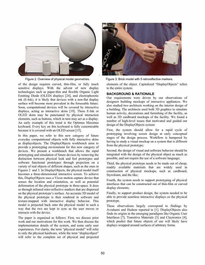
of the design requires curved, thin-film, or fully touch sensitive displays. With the advent of new display technologies such as paper-thin and flexible Organic Light Emitting Diode (OLED) displays [24], and electrophoretic ink (E-Ink), it is likely that devices with a non-flat display surface will become more prevalent in the forseeable future. Soon, computational devices will be covered by interactive displays, acting as interactive skins [19]. These E-Ink or OLED skins may be punctuated by physical interaction elements, such as buttons, which in turn may act as a display. An early example of this trend is the Optimus Maximus keyboard. Every key on this keyboard is fully customizable because it is covered with an OLED screen [15]. In this paper, we refer to this new category of future everyday computational objects with fully interactive skins as displayobjects. The DisplayObjects workbench aims to provide a prototyping environment for this new category of devices. We present a workbench that allows the rapid prototyping and simulation of future devices by removing the distinction between physical look and feel prototypes and software functional prototypes through projection on a variety of real objects of different shapes, such as the ones in Figures 2 and 3. In DisplayObjects, the physical model itself becomes a three-dimensional interactive screen. To achieve this, DisplayObjects uses a Vicon motion capture device that senses the location and orientation, as well as potential deformation of the physical prototype in three-space. It does so through infrared retro-reflective markers that are dispersed on the physical prototype’s surface. An accurate 3D model of the physical prototype is then rendered in software and texture-mapped with interactive display behavior. This model is projected back onto the physical model in such a way that the two are kept in sync as the user moves or interacts with the device. The paper is organized as follows: First, we discuss prior work and our motivations for this work. We then discuss the implementation details of the system, and some early user experiences. For clarity, the term “physical model” will refer to only the physical hardware, while the term “displayobject” will refer to the complete set of physical and projected
elements of the object. Capitalized “DisplayObjects” refers to the entire system.
BACKGROUND & RATIONALE Our requirements were driven by our observations of designers building mockups of interactive appliances. We also studied two architects working on the interior design of a building. The architects used both 3D graphics to simulate human activity, decorations and furnishing of the facility, as well as 3D cardboard mockups of the facility. We found a number of high-level issues that motivated and guided our design of the DisplayObjects system: First, the system should allow for a rapid cycle of prototyping involving screen design at early conceptual stages of the design process. Workflow is hampered by having to study a visual mockup on a system that is different from the physical prototype; Second, the design of visual and software behavior should be integrated with the design of the physical object as much as possible, and not require the use of a software language; Third, the physical prototype needs to be made out of cheap, readily available materials that are widely used in construction of physical mockups, such as cardboard, Styrofoam, and the like; Fourth, the system needs to support prototyping of physical interfaces that can be constructed out of thin-film or curved display elements; Finally, to support product design, the system needed to be able to provide seamless interactive displays on the physical prototype. These observations largely correspond to findings by Avrahami and Hudson reported in [1]. DisplayObjects also finds its origins in the emerging paradigms like Organic User Interfaces [7], Transitive Materials [3] and Claytronics [4], which predict that future objects of use will likely have displays wrapped around surfaces of arbitrary forms.
Figure 2. Overview of physical model geometries. Figure 3. Brick model with 5 retroreflective markers.
50
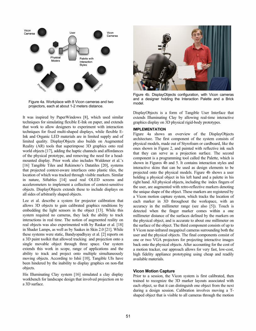
Figure 4a. Workplace with 8 Vicon cameras and two projectors, each at about 1-2 meters distance.
It was inspired by PaperWindows [8], which used similar techniques for simulating flexible E-Ink on paper, and extends that work to allow designers to experiment with interaction techniques for fixed multi-shaped displays, while flexible E-Ink and Organic LED materials are in limited supply and of limited quality. DisplayObjects also builds on Augmented Reality (AR) tools that superimpose 3D graphics onto real world objects [17], adding the haptic channels and affordances of the physical prototype, and removing the need for a head-mounted display. Prior work also includes Waldener et al.’s [16] Tangible Tiles and Rekimoto’s Datatiles [20], systems that projected context-aware interfaces onto plastic tiles, the location of which was tracked through visible markers. Similar in nature, Siftables [14] used real OLED screens and accelerometers to implement a collection of context-sensitive objects. DisplayObjects extends these to include displays on all sides of arbitrarily shaped objects. Lee et al. describe a system for projector calibration that allows 3D objects to gain calibrated graphics renditions by embedding the light sensors in the object [13]. While this system required no cameras, they lack the ability to track interactions in real time. The notion of augmented reality on real objects was also experimented with by Raskar et al. [18] in Shader Lamps, as well as by Saakes in Skin 2.0 [21]. While these systems were static, Bandyopadhyay et al. [2] reports on a 3D paint toolkit that allowed tracking and projection onto a single movable object through three space. Our system extends this work in scope, range of applications and the ability to track and project onto multiple simultaneously moving objects. According to Ishii [10], Tangible UIs have been hindered by the inability to display graphics on non-flat objects. His Illuminating Clay system [16] simulated a clay display workbench for landscape design that involved projection on to a 3D surface.
Figure 4b. DisplayObjects configuration, with Vicon cameras and a designer holding the Interaction Palette and a Brick model. DisplayObjects is a form of Tangible User Interface that extends Illuminating Clay by allowing real-time interactive graphics display on 3D physical rigid-body prototypes.
IMPLEMENTATION Figure 4a shows an overview of the DisplayObjects architecture. The first component of the system consists of physical models, made out of Styrofoam or cardboard, like the ones shown in Figure 2, and painted with reflective ink such that they can serve as a projection surface. The second component is a programming tool called the Palette, which is shown in Figures 4b and 5. It contains interaction styles and interactive skins that can be used as design elements to be projected onto the physical models. Figure 4b shows a user holding a physical object in his left hand and a palette in his right hand. All physical objects, including the index fingers of the user, are augmented with retro-reflective markers denoting the unique shape of the object. These markers are registered by a Vicon motion capture system, which tracks the location of each marker in 3D throughout the workspace, with an accuracy in the millimeter range (see also [5]). Touch is detected when the finger marker comes within a one millimeter distance of the surfaces defined by the markers on the physical object, and is accurate to about one millimeter on the surface of the object. The third component consists of up to 8 Vicon near-infrared megapixel cameras surrounding both the user and the physical objects. The final components consist of one or two VGA projectors for projecting interactive images back onto the physical objects. After accounting for the cost of a motion tracker, our approach allows for very fast, low-cost, high fidelity appliance prototyping using cheap and readily available materials.
Vicon Motion Capture Prior to a session, the Vicon system is first calibrated, then trained to recognize the 3D marker layouts associated with each object, so that it can distinguish one object from the next during a design session. Calibration involves moving a T-shaped object that is visible to all cameras through the motion
51
capture space, while training involves introducing the object into the space one by one, and recording the location of its markers. While calibration has to occur whenever cameras have moved, training is only done once. The Vicon system communicates with the DisplayObjects software architecture using a TCP/IP connection over Ethernet that minimizes latency.
Software Models The surfaces of each physical object are modeled by selecting shapes from a default set of 3D geometries consisting of spheres, cylinders, cubes and the like, or by designing a custom shape using a 3D drawing tool. The 3D model of the object is then passed on to the DisplayObjects framework, which was written in Objective-C on Mac OS X using the Cocoa framework. The software uses Quartz Composer, a Mac OS X real-time multimedia visual programming package that renders directly in OpenGL to display the scene. Quartz Composer was chosen because of its ease of configuration and its ability to texture objects with a variety of (interactive) visual formats, including video, making it an excellent platform for quick visual prototyping of behaviors through a simple graphical language. Object surfaces are texture-mapped with interactive graphics obtained from Quartz Composer source objects, which range from video feeds, to custom Quartz patches, screen captures, Quicktime movies, Flash content and live webpages. The DisplayObjects framework also provides the mapping between the real-time raw Vicon motion capture data, which it obtains over an Ethernet connection from the Vicon system. Once a Vicon geometry is matched with that of a 3D object model, the position and orientation of the Vicon geometry controls the 3D movements of the 3D software model. Projecting the Displayobject The rendered Quartz Composer scene is passed to a number of projectors that are aimed at the corresponding physical
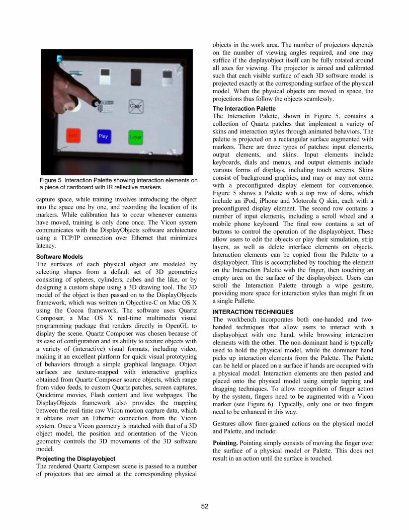
objects in the work area. The number of projectors depends on the number of viewing angles required, and one may suffice if the displayobject itself can be fully rotated around all axes for viewing. The projector is aimed and calibrated such that each visible surface of each 3D software model is projected exactly at the corresponding surface of the physical model. When the physical objects are moved in space, the projections thus follow the objects seamlessly. The Interaction Palette The Interaction Palette, shown in Figure 5, contains a collection of Quartz patches that implement a variety of skins and interaction styles through animated behaviors. The palette is projected on a rectangular surface augmented with markers. There are three types of patches: input elements, output elements, and skins. Input elements include keyboards, dials and menus, and output elements include various forms of displays, including touch screens. Skins consist of background graphics, and may or may not come with a preconfigured display element for convenience. Figure 5 shows a Palette with a top row of skins, which include an iPod, iPhone and Motorola Q skin, each with a preconfigured display element. The second row contains a number of input elements, including a scroll wheel and a mobile phone keyboard. The final row contains a set of buttons to control the operation of the displayobject. These allow users to edit the objects or play their simulation, strip layers, as well as delete interface elements on objects. Interaction elements can be copied from the Palette to a displayobject. This is accomplished by touching the element on the Interaction Palette with the finger, then touching an empty area on the surface of the displayobject. Users can scroll the Interaction Palette through a wipe gesture, providing more space for interaction styles than might fit on a single Pallette.
INTERACTION TECHNIQUES The workbench incorporates both one-handed and two-handed techniques that allow users to interact with a displayobject with one hand, while browsing interaction elements with the other. The non-dominant hand is typically used to hold the physical model, while the dominant hand picks up interaction elements from the Palette. The Palette can be held or placed on a surface if hands are occupied with a physical model. Interaction elements are then pasted and placed onto the physical model using simple tapping and dragging techniques. To allow recognition of finger action by the system, fingers need to be augmented with a Vicon marker (see Figure 6). Typically, only one or two fingers need to be enhanced in this way.
Gestures allow finer-grained actions on the physical model and Palette, and include:
Pointing. Pointing simply consists of moving the finger over the surface of a physical model or Palette. This does not result in an action until the surface is touched.
Figure 5. Interaction Palette showing interaction elements on a piece of cardboard with IR reflective markers.
52
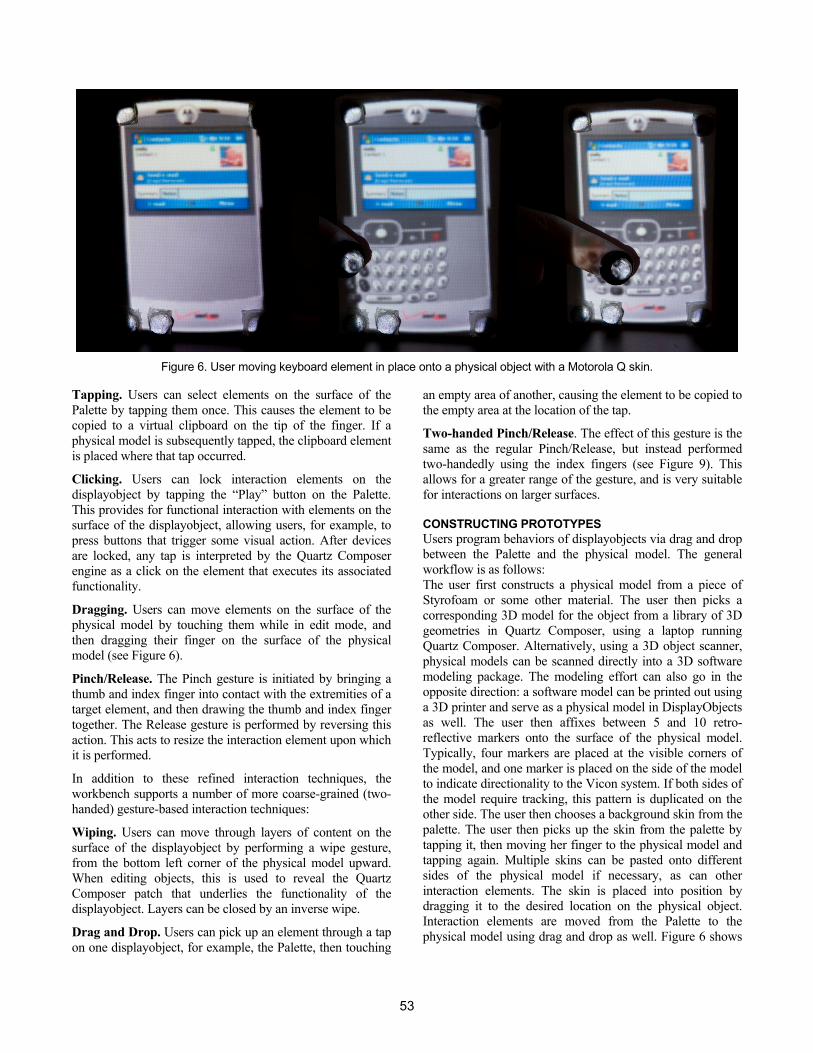
Figure 6. User moving keyboard element in place onto a physical object with a Motorola Q skin.
Tapping. Users can select elements on the surface of the Palette by tapping them once. This causes the element to be copied to a virtual clipboard on the tip of the finger. If a physical model is subsequently tapped, the clipboard element is placed where that tap occurred.
Clicking. Users can lock interaction elements on the displayobject by tapping the “Play” button on the Palette. This provides for functional interaction with elements on the surface of the displayobject, allowing users, for example, to press buttons that trigger some visual action. After devices are locked, any tap is interpreted by the Quartz Composer engine as a click on the element that executes its associated functionality.
Dragging. Users can move elements on the surface of the physical model by touching them while in edit mode, and then dragging their finger on the surface of the physical model (see Figure 6).
Pinch/Release. The Pinch gesture is initiated by bringing a thumb and index finger into contact with the extremities of a target element, and then drawing the thumb and index finger together. The Release gesture is performed by reversing this action. This acts to resize the interaction element upon which it is performed.
In addition to these refined interaction techniques, the workbench supports a number of more coarse-grained (two-handed) gesture-based interaction techniques:
Wiping. Users can move through layers of content on the surface of the displayobject by performing a wipe gesture, from the bottom left corner of the physical model upward. When editing objects, this is used to reveal the Quartz Composer patch that underlies the functionality of the displayobject. Layers can be closed by an inverse wipe.
Drag and Drop. Users can pick up an element through a tap on one displayobject, for example, the Palette, then touching
an empty area of another, causing the element to be copied to the empty area at the location of the tap.
Two-handed Pinch/Release. The effect of this gesture is the same as the regular Pinch/Release, but instead performed two-handedly using the index fingers (see Figure 9). This allows for a greater range of the gesture, and is very suitable for interactions on larger surfaces. CONSTRUCTING PROTOTYPES Users program behaviors of displayobjects via drag and drop between the Palette and the physical model. The general workflow is as follows: The user first constructs a physical model from a piece of Styrofoam or some other material. The user then picks a corresponding 3D model for the object from a library of 3D geometries in Quartz Composer, using a laptop running Quartz Composer. Alternatively, using a 3D object scanner, physical models can be scanned directly into a 3D software modeling package. The modeling effort can also go in the opposite direction: a software model can be printed out using a 3D printer and serve as a physical model in DisplayObjects as well. The user then affixes between 5 and 10 retro-reflective markers onto the surface of the physical model. Typically, four markers are placed at the visible corners of the model, and one marker is placed on the side of the model to indicate directionality to the Vicon system. If both sides of the model require tracking, this pattern is duplicated on the other side. The user then chooses a background skin from the palette. The user then picks up the skin from the palette by tapping it, then moving her finger to the physical model and tapping again. Multiple skins can be pasted onto different sides of the physical model if necessary, as can other interaction elements. The skin is placed into position by dragging it to the desired location on the physical object. Interaction elements are moved from the Palette to the physical model using drag and drop as well. Figure 6 shows
53
a mobile messenger device with a background skin and 320 x 240 display element. The user has picked up a keyboard from the palette. When she taps on the empty surface area of the skin, the keyboard is placed onto the physical model. By dragging the finger around the surface of the object, the keyboard is moved to its desired location. This operation requires considerable accuracy of the system, which, depending on the distance of the Vicon cameras to the physical object, is about one millimeter. Programming Interaction Elements After display elements are placed on the physical model, a script generates a Quartz file for the displayobject that can be edited in one of three ways: on a computer, on the Palette, or on the physical model itself. The physical model is placed in edit mode by pressing a button on the Palette, or by providing a wipe gesture on its surface. To connect input elements with output elements, users drag connectors from the outlets of the former onto the inlets of the latter in Quartz Composer on a laptop. A screen element, in turn, is scripted through the contents of a movie file connected to one of its inlets. Simple interactive behaviors are limited to simple actions, such as starting, stopping or scrolling through the movie file displayed on the screen element. More complicated behaviors are made possible by dragging Quartz Composer subpatches from the palette onto the physical model, and connecting inlets and outlets. These subpatches are programmed on the computer, rather than on the displayobjects. Because subpatches are a regular part of Quartz Composer, they may contain Objective-C code to further extend behaviors ranging from video feeds, to screen captures, Flash content, live webpages, etc.
Mixing Bits and Atoms Because displayobjects are made out of real materials, it is easy to extend their behaviors with real world artifacts as well, mixing properties of bits with those of atoms [11]. For example, paper sketches or physical buttons can be easily affixed on the physical prototype, and linked with interactive content. This not only allows quick iterative revisions of the physical model, but also allows for physical elements to be mixed with digital elements, for example, to provide haptic feedback for an on-screen input element. One example of this is the use of physical pushpins to simulate surface effects of buttons displayed on the surface. This allows for haptic feedback when interacting with the physical prototype. CASE STUDIES We observed the use of DisplayObjects for prototyping by groups of design students in a graduate course in user interface design. Students got an opportunity to rapidly prototype some physical forms, and then design interactive graphics for these shapes. We now discuss experiences of students from two of the design projects in that course.
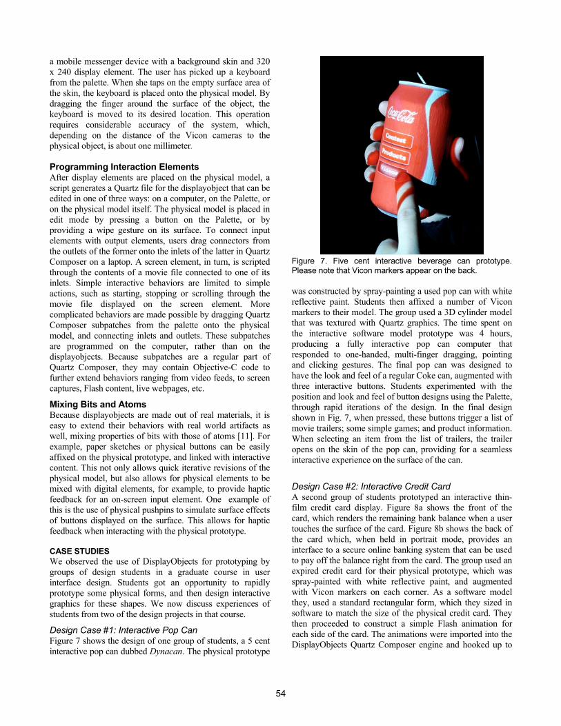
Design Case #1: Interactive Pop Can Figure 7 shows the design of one group of students, a 5 cent interactive pop can dubbed Dynacan. The physical prototype
was constructed by spray-painting a used pop can with white reflective paint. Students then affixed a number of Vicon markers to their model. The group used a 3D cylinder model that was textured with Quartz graphics. The time spent on the interactive software model prototype was 4 hours, producing a fully interactive pop can computer that responded to one-handed, multi-finger dragging, pointing and clicking gestures. The final pop can was designed to have the look and feel of a regular Coke can, augmented with three interactive buttons. Students experimented with the position and look and feel of button designs using the Palette, through rapid iterations of the design. In the final design shown in Fig. 7, when pressed, these buttons trigger a list of movie trailers; some simple games; and product information. When selecting an item from the list of trailers, the trailer opens on the skin of the pop can, providing for a seamless interactive experience on the surface of the can.
Design Case #2: Interactive Credit Card A second group of students prototyped an interactive thin-film credit card display. Figure 8a shows the front of the card, which renders the remaining bank balance when a user touches the surface of the card. Figure 8b shows the back of the card which, when held in portrait mode, provides an interface to a secure online banking system that can be used to pay off the balance right from the card. The group used an expired credit card for their physical prototype, which was spray-painted with white reflective paint, and augmented with Vicon markers on each corner. As a software model they, used a standard rectangular form, which they sized in software to match the size of the physical credit card. They then proceeded to construct a simple Flash animation for each side of the card. The animations were imported into the DisplayObjects Quartz Composer engine and hooked up to
Figure 7. Five cent interactive beverage can prototype. Please note that Vicon markers appear on the back.
54
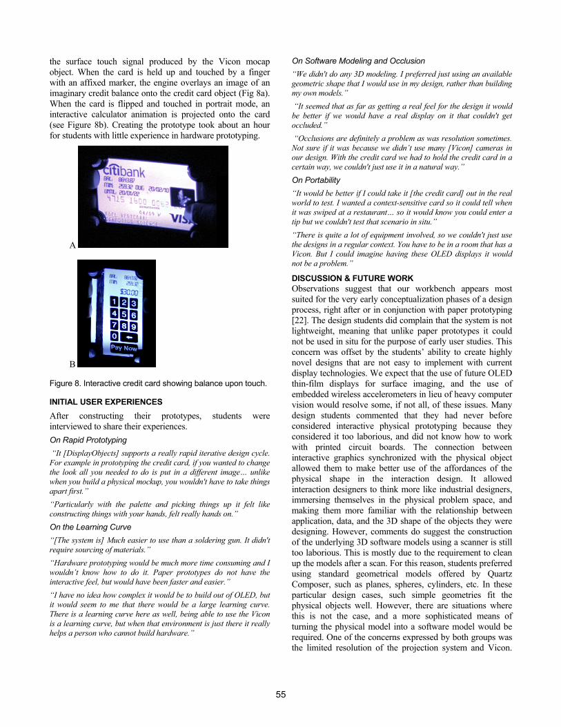
the surface touch signal produced by the Vicon mocap object. When the card is held up and touched by a finger with an affixed marker, the engine overlays an image of an imaginary credit balance onto the credit card object (Fig 8a). When the card is flipped and touched in portrait mode, an interactive calculator animation is projected onto the card (see Figure 8b). Creating the prototype took about an hour for students with little experience in hardware prototyping.
A
B
Figure 8. Interactive credit card showing balance upon touch.
INITIAL USER EXPERIENCES After constructing their prototypes, students were interviewed to share their experiences. On Rapid Prototyping “It [DisplayObjects] supports a really rapid iterative design cycle. For example in prototyping the credit card, if you wanted to change the look all you needed to do is put in a different image… unlike when you build a physical mockup, you wouldn't have to take things apart first.” “Particularly with the palette and picking things up it felt like constructing things with your hands, felt really hands on.” On the Learning Curve “[The system is] Much easier to use than a soldering gun. It didn't require sourcing of materials.” “Hardware prototyping would be much more time consuming and I wouldn’t know how to do it. Paper prototypes do not have the interactive feel, but would have been faster and easier.” “I have no idea how complex it would be to build out of OLED, but it would seem to me that there would be a large learning curve. There is a learning curve here as well, being able to use the Vicon is a learning curve, but when that environment is just there it really helps a person who cannot build hardware.”
On Software Modeling and Occlusion “We didn't do any 3D modeling. I preferred just using an available geometric shape that I would use in my design, rather than building my own models.” “It seemed that as far as getting a real feel for the design it would be better if we would have a real display on it that couldn't get occluded.” “Occlusions are definitely a problem as was resolution sometimes. Not sure if it was because we didn’t use many [Vicon] cameras in our design. With the credit card we had to hold the credit card in a certain way, we couldn't just use it in a natural way.” On Portability “It would be better if I could take it [the credit card] out in the real world to test. I wanted a context-sensitive card so it could tell when it was swiped at a restaurant… so it would know you could enter a tip but we couldn't test that scenario in situ.” “There is quite a lot of equipment involved, so we couldn't just use the designs in a regular context. You have to be in a room that has a Vicon. But I could imagine having these OLED displays it would not be a problem.”
DISCUSSION & FUTURE WORK Observations suggest that our workbench appears most suited for the very early conceptualization phases of a design process, right after or in conjunction with paper prototyping [22]. The design students did complain that the system is not lightweight, meaning that unlike paper prototypes it could not be used in situ for the purpose of early user studies. This concern was offset by the students’ ability to create highly novel designs that are not easy to implement with current display technologies. We expect that the use of future OLED thin-film displays for surface imaging, and the use of embedded wireless accelerometers in lieu of heavy computer vision would resolve some, if not all, of these issues. Many design students commented that they had never before considered interactive physical prototyping because they considered it too laborious, and did not know how to work with printed circuit boards. The connection between interactive graphics synchronized with the physical object allowed them to make better use of the affordances of the physical shape in the interaction design. It allowed interaction designers to think more like industrial designers, immersing themselves in the physical problem space, and making them more familiar with the relationship between application, data, and the 3D shape of the objects they were designing. However, comments do suggest the construction of the underlying 3D software models using a scanner is still too laborious. This is mostly due to the requirement to clean up the models after a scan. For this reason, students preferred using standard geometrical models offered by Quartz Composer, such as planes, spheres, cylinders, etc. In these particular design cases, such simple geometries fit the physical objects well. However, there are situations where this is not the case, and a more sophisticated means of turning the physical model into a software model would be required. One of the concerns expressed by both groups was the limited resolution of the projection system and Vicon.
55
We hope to include an HD projector in future versions of the system, and upgrade the Vicon hardware to 4 MPixel cameras to help resolve these issues. An important problem was the occlusion of projection or markers on the displayobjects. The primary form of occlusion occurs when the finger or hand casts a shadow onto the displayobject, when using a single projector. This is resolved by projecting with two projectors from two different angles [13]. While it is possible to seamlessly project two camera views of the same model from two different viewports, differences in light intensity are not currently corrected for. This can result in uneven illumination of surfaces. Solutions to this problem are known but beyond the scope of this paper (see [2] for a discussion). The second form of occlusion is when a hand or object covers markers from view by the mocap system. This is best resolved through the use of more cameras, and by placing cameras in a circular arrangement around objects and user.
CONCLUSIONS We discussed DisplayObjects, a rapid prototyping workbench that allows functional interfaces to be designed on 3D physical objects. DisplayObjects adds 3D skins on objects of arbitrary shape, and targets a much earlier stage of physical design with functional prototyping than normally possible. Our initial interviews suggest that novice design teams can create physical prototypes with functional content fast, and with little effort.
REFERENCES 1. Avrahami, D. and Hudson, S.E. Forming Interactivity: A Tool
for Rapid Prototyping of Physical Interactive Products. In Proceedings of the ACM Symposium on Designing Interactive Systems (DIS’02), pp. 141-146, 2002.
2. Bandyopadhyay, Raskar, R., and H. Fuchs. Dynamic Shader Lamps: Painting on Movable Objects. In Proceedings of In Proceedings of Eurographics Workshop on Rendering, 2001.
3. Coelho M., Poupyrev, I., Sadi, S., Vertegaal, R., Berzowska, J., Buechley, L., Maes, P. and Oxman, N. Programming Reality: From Transitive Materials to Organic User Interfaces (Workshop). In Proceedings of CHI 2009, ACM Press, 2009 (in press).
4. Goldstein, S., et al. Programmable matter. IEEE Computer 38, 2005, 99–101.
5. Grossman, T., Wigdor, D., and Balakrishnan, R. 2005. Multi-finger gestural interaction with 3D volumetric displays. In Proceedings of ACM SIGGRAPH 2005 Papers. ACM, Los Angelos, California, 2005, 931-931.
6. Hartmann, B., Klemmer, S. R., Bernstein, M., Abdulla, L., Burr, B., Robinson-Mosher, A., and Gee, J. 2006. Reflective physical prototyping through integrated design, test, and analysis. In Proceedings of UIST '06. ACM, New York, NY, 2006, 299-308.
7. Holman, D. and Vertegaal, R. Organic User Interfaces: Designing Computers in Any Way, Shape, or Form. Communications of the ACM, vol. 51 (6), 2008.
8. Holman, D., Vertegaal, R. and Altosaar, M. PaperWindows: Interaction Techniques for Digital Paper. In Proc. CHI 2005, ACM Press (2005), 591-599.
9. Hudson, S. and Mankoff, J. Rapid Construction of Functioning Physical Interfaces from Cardboard, Thumbtacks, Tin Foil and Masking Tape. In Proceedings of UIST’06, October 15–18, 2006, Montreux, Switzerland.
10. Ishii, H. The Tangible User Interface and its Evolution. Commun. ACM Volume 51, Issue 6, 2008, 32-36.
11. Ishii, H., and Ullmer, B. Tangible Bits: Towards Seamless Interfaces between People, Bits and Atoms. In Proc. CHI 1997, ACM Press (1997), 234-241.
12. Lee, J.C., Avrahami1, D., Hudson, S.E., Forlizzi, J., Dietz, P.H., Leigh, D. The Calder Toolkit: Wired and Wireless Components for Rapidly Prototyping Interactive Devices. In Proceedings of DIS 04, Cambridge, MA, USA, 2004.
13. Lee, J.C., Dietz, P. H., Maynes-Aminzade, D., Raskar, R., Hudson, S.E. Automatic Projector Calibration with Embedded Light Sensors. In Proceedings of UIST ’04, October 24–27, 2004, Santa Fe, New Mexico, USA.
14. Merrill, D., Kalanithi, J., and Maes, P. Siftables: Towards Sensor Network User Interfaces. In Proceedings of the 1st international conference on Tangible and Embedded Interaction, February 15-17, 2007, Baton Rouge, Louisiana.
15. Optimus. Optimus Maximus Keyboard, http://www.artlebedev.com/everything/optimus/, 2008.
16. Piper, B., Ratti, C., and Ishii, H. Illuminating Clay: A 3-D Tangible Interface for Landscape Analysis. In Proceedings of the CHI '02. ACM, Minneapolis, 2002, 355-362.
17. Prince, S., Cheok, A.D., Farbiz, F., Williamson, T., Johnson, N., Billinghurst, M., and H. Kato: 3D Live: Real Time Captured Content for Mixed Reality. ISMAR 2002, 317.
18. Raskar, R., G. Welch, and K.-L. Low. Shader Lamps: Animating Real Objects with Image-based Illumination. In Proceedings of Eurographics Workshop on Rendering, 2001.
19. Rekimoto, J. SmartSkin: an infrastructure for freehand manipulation on interactive surfaces. In Proceedings of CHI '02. ACM, Minneapolis, 113-120.
20. Rekimoto, J., Ullmer, B., and Oba, H. 2001. DataTiles: a modular platform for mixed physical and graphical interactions. In Proceedings of CHI '01. ACM, Seattle, WA, 2001, 269-276.
21. Saakes, D.P. Material Light : Exploring Expressive Materials. In Personal and Ubiquitous Computing: Volume 10, Issue 2-3, 2006.
22. Snyder, C. Paper Prototyping: The Fast and Easy Way to Design and Refine User Interfaces. Morgan Kaufmann, 2003.
23. Villar, N. and Gellersen, H. A Malleable Control Structure for Softwired User Interfaces. In Proceedings of Tangible and Embedded Interaction (TEI’07), 2007.
24. Williams, M. Sony, Philips Unveil Flexible OLED Displays. PC World, May 25th, 2007.
56