displacement sensor od - lpc uk · placement sensor in the od series. optics, switches and signal...
TRANSCRIPT

D i s p l a c e m e n t S e n s o r O DD
AT
AS
HE
ET

2 SENSICK
Scanner and measuring
system at the same time
Laser diode
Collimator
Test object
PSD
Reception Lens
A
B
Triangulation measurement: The site
of the light spot on the PSD detector is
dependent on the distance of the detected
object. The signals A and B change de-
pending on the position of the light spot.
The calculation of the signals in the micro-
controller then gives a linear output signal
depending on the distance of the object.
The all-in-one sensor with proven PSD
technology: The proven triangulation meas-
urement is the physical basis of the dis-
placement sensor in the OD series. Optics,
switches and signal processing are design-
ed for the highest resolutions with simulta-
neously high linearity.
Displacement Sensors from the OD Series
T
Displacement Sensor
The displacement sensors of theOD series are scanners and meas-uring systems at the same time.Thanks to intelligent microcontrollertechnology, we have been able tocombine all functions in a compactdevice for the first time: precisemeasuring and reliable presencecontrol, this sensor can do both.
The calibration of the analog outputand the setting of the scanningrange of the control output is easywith Teach-in.
There are components in almost allmanufacturing sectors that mustfulfill the highest demands for preci-sion and optics. The displacementsensors of the OD series detectthe smallest deviations, depress-ions or lack of flatness immediatelyeven in the µm range.
Type with metal housing and aclass 2 laser is suited for applica-tions that require the smallest spotdimensions for precise measuring.The plastic model OD 25 with redLED light source is suited for large-area recording of raw surfaces.
Temperature ranges between–10 and +40 °C as well as humidor dusty environments are nolonger a problem.

3SENSICK
OD
Electronics indu-
stry: Checking the
switching behavior of
relay contacts and
mechanical switches
with an OD displace-
ment sensor.
Checking the IC con-
tacts before assemb-
ling boards. Making
sure whether electri-
cal components are
present.
Paper and packaging industry: Checking wave shapes and heights in cardboard production
in cardboard packaging. The large light spot of the LED model enables measuring raw surfaces.
Presence checks and checks of the curves of bottles and beaker caps. Multicolored surfaces
do not affect the measuring behavior.
Robotics: Alignment and targeted control of robot arms and control of welding robots in
special purpose engineering or in mass production with an OD displacement sensor.
Automobile industry: Measuring
raw and low-reflection engine and
gear components with an OD dis-
placement sensor. Localization and
checking of welds and bodywork
parts in passenger car mass produc-
tion. Multicolored surfaces are de-
tected reliably.
Semiconductor industry:
Measuring the epoxy resin
deposit in IC manufacturing with
the OD displacement sensor.
Detection of missing ICs in the
packaging of blister tapes. The
OD is also designed for low-re-
flecting, light-absorbing surfaces.

4 SENSICK
Setting and calibration
with Teach-in
Laser and LED models
Blanking input for synchroni-
zation for demanding
measurement jobs
Displacement Sensor
Description of the operating panel
DISTANCEOUT STAB.
TEACH
TEACH OFFSET
RUNOFF D. RUN
SET
100 ms
10 ms1 ms
AUTO
BLACKWHITE
RESPONSE SENS.
When the blanking input is active, the control and the analog output retain their previousstatus (PNP type: active – level is HIGH; NPN type: active – level is LOW.)
Description of the blanking input (SH)
Measuring MeasuringHold Hold
Hold Hold
Analogoutput
Controloutput
Blankinginput
Active
OFF
Setting options
OD 25-05P132
OD 25-05P830
OD 25-05N132
OD 25-05N830
OD 50-10P142
OD 50-10P840
OD 50-10N142
OD 50-10N840
1
2
2
3
4
5
6
7
3
4
5
6
7
1
Displacement Sensors from the OD Series
DISTANCEOUT STAB.
TEACH
TEACH OFFSET
RUNOFF D. RUN
SET
100 ms
10 ms1 ms
AUTO
FIXSET
RESPONSE SENS.
2
3
4
5
6
8
1
Setting options
OD 30-04P142
OD 30-04P840
OD 30-04N142
OD 30-04N840
OD 100-35P142
OD 100-35P840
OD 100-35N142
OD 100-35N840
OD 130-50P142
OD 130-50P840
OD 130-50N142
OD 130-50N840
OD 250-150P142
OD 250-150P840
OD 250-150N142
OD 250-150N840
8
Output indicator/Teach-in indicator
In the RUN mode, the LED display shows the “open
collector” status: orange = output ON; off or does
not light = output OFF.
Response time with 3 positions
The positions 100 ms, 10 ms, and 1 ms are selected
depending on the desired response time and resolu-
tion. The longer the response time, the better the
resolution.
Distance indicator (DISTANCE)
Display for the distance from the sensor front to the
object. In the scanning range: LED display lights red
(closer than middle), orange (middle), or green (farther
than middle). This distance indicator blinks red-green
when the object is out of the measurement range.
Stable indicator (STAB.)
The LED display lights green when there is light re-
ception with reserve. It does not light when there is
sufficient reception, and it lights red if reflectance is
too weak or strong.
Teach-in button – Set mode (during Teach-in)
a) Setting the scanning distance: The LED lights
green 1x when the first distance is set and 2x
when the second distance is set. It lights red 1x
if there is an operating error.
b) Setting the offset: The LED lights green 3x when
the offset is set. It lights red 1x if there is an oper-
ating error.
c) Resetting the offset: The LED lights green 3x when
the offset is reset.
Mode selector with 3 positions
The positions SET, RUN, and RUN with OFF DELAY
are required for Teach-in.
OD 25 / OD 50:
Sensitivity selector with 3 positions
WHITE (white object), BLACK (black object), and
AUTO (gray and/or multicolored object). WHITE or
BLACK is selected dependent on the reflection when
the selector is set to AUTO.
OD 30/OD 100/OD 130/OD 250:
AUTO: Automatic amplifier control (gain) depending
on reflectance.
SET/FIX: Switch setting SET: Reflectance is taught be
Teach-in. Switch setting FIX: Amplification is set after
Teach-in with the switching function FIX.

5SENSICK
Selectable offset range (2nd setting)
Selectable offset range (1st setting)
LED lights orange
Middle (12 mA)
Middle after setting (12 mA)
Default setting
After setting the offset range
Teach
1. Position of the sensor
2. Teach-in calibration of the analog output
Teach
Teach
Object in scanning distance 1
Object in scanning distance 2
Beschreibung Funktionen
Two steps for calibra-
ting the analog output
1. Position the object at theaverage scanning distance.The LED distance indicatorlights orange.
2. Switch the Mode selector toSET. Press the Teach-in but-ton for 2 to 5 seconds or trig-ger it via the connectingcable. The Teach-in displaylights green 3x. Switch theMode selector to RUN orRUN with OFF DELAY: thecalibration is adopted.
The Teach-in input is independ-ent of the position of the Modeselector.
Two steps for
resetting the offset
1. Switch the Mode selector toSET.
2. Press the Teach-in button lon-ger than 5 seconds or triggerit via the connecting cable.
Three steps for setting
the control output
1. Switch the Mode selector toSET. Position the object at thescanning distance 1. Pressthe Teach-in button for fewerthan 2 seconds or trigger itvia the connecting cable.
2. Position the object at thescanning distance 2. Pressthe Teach-in button for fewerthan 2 seconds or trigger itvia the connecting cable.
3. Switch the Mode selector toRUN or RUN with OFF DELAY.
The Teach-in input is independ-ent of the position of the Modeselector.
* The hysteresis depends onthe response time: the longerthe response time, the smallerthe hysteresis. The basic princi-ple applies: the higher thereflectance, the smaller thehysteresis.
OD

6 SENSICK
Teach-in indicator/output indicator
Response time selector
Distance indicator
Stable indicator
Teach-in button
Mode selector
Sensitivity selectorMounting hole, ø 4.5 mm
Connecting cable 2 m (optional 5 m)
or M 12 plug; 90° rotatable
Setting options
Lichtschranken Baureihe WL 27-2Lichtschranken Baureihe WL 27-2Displacement Sensors from the OD Series
Connection type
Dimension illustration
1
2
3
4
5
6
7
8
42.4 3.8
4.3
51
.4
50
21
.24
3.2
26
.73
9.7
60
20.4
ø 4.5
Q
TI
0 V/M
(shield)
SH
QA
brn12–24 V DC/L+
gra
wht
blk
pnk
blu
0 V/M
Q
SH
TI
(shield)
NN.C.
NN.C.
QA
brn 112–24 V DC/L+
2
3
4
5
6
7
8
wht
blu
blk
gra
pnk
vio
ora
9
8-pin, M 126 x 0.2 mm2
OD 25-05P132
OD 25-05P830
OD 25-05N132
OD 25-05N830
OD 50-10P142
OD 50-10P840
OD 50-10N142
OD 50-10N840
OD 25-05P132
OD 25-05N132
OD 50-10P142
OD 50-10N142
OD 25-05P830
OD 25-05N830
OD 50-10P840
OD 50-10N840
Accessories
ODC evaluation unit
Cable receptacle with cable
Measuring range25 ± 5/50 ± 10 mm
Displacement Sensor
OD 25 OD 50
8
98
DISTANCEOUT STAB.
TEACH
TEACH OFFSET
RUNOFF D. RUN
SET
100 ms
10 ms1 ms
AUTO
BLACKWHITE
RESPONSE SENS.
2
3
4
5
6
7
1

7SENSICK
OD
Ordering information
Sens
or
Distance [mm]605040
Ø 0.7 mm Ø 0.5 mm Ø 0.5 mm
90 %
Dev
iatio
n [%
]
Distance [mm]
-3-2
6% 18 %
-1
3210
605545 5040
Dev
iatio
n [%
]
Distance [mm]3027.52522.520
6 % 18 %
90 %
3210-1-2-3
Distance [mm]
Sens
or
302520
Ø 1.5 mm Ø 1.5 mm Ø 1.8 mm
Deviation OD 25-05 (LED)
Light spot diameter OD 25-05 (LED)
Deviation OD 50-10 (Laser)
Light spot diameter OD 50-10 (Laser)
1 2
3
1 2
3
Technical data OD
Measuring range 25 ± 5 mm
50 ± 10 mm
Light source LED, red light
Laser class 2 IEC 60825: 1998
Analog output 4–20 mA , 0–300 ΩControl output 1) PNP; 30 V/100 mA Open collector
NPN; 30 V/100 mA Open collector
Accuracy ±1 % FS 2)/18 % – 90 %, ±4 % FS 2)/6 %
Linearity ±1 % FS 2)/18 % – 90 %, ±3 % FS 2)/6 %
Drift ± 0.05 %/°C FS 2)
± 0.02 %/°C FS 2)
Resolution of analog output 3) 3/10/30 µm, 100/10/1 ms
Hysteresis of control output 10/30/100 µm (90 % remission)
30/120/500 µm (6 % remission)
Analog output freq. response – 3 dB 100 ms – 6.7/s, 10 ms – 54/s, 1 ms – 770/s
Teach-in input (TI) NPN LOW = active, PNP HIGH = active
Hold input (SH) NPN LOW = active, PNP HIGH = active
Timer 40 ms off delay
VDE protection class III
Sensitivity to ambient light 10000 lx (sun), 3000 lx (artificial light)
Supply voltage VS 12–24 V DC , –5 %/+10 %
Power consumption 4) 120 mA (at 24 V)
Warmup time 5) 15 min maximum
EMC EN 50081-2, EN 50082-2
Enclosure rating IP 67
Circuit protection 6) A, B, D
Ambient temperature TA7) Operation: –10 ... +40 °C
Storage: –20 ... +60 °C
Connection Cable 2 m 8)
Plug 9)
Housing PBT (housing), Glass (window)
Zinc (housing), Glass (window)
25-05P132
25-05P830
25-05N132
25-05N830
50-10P142
50-10P840
50-10N142
50-10N840
Type
OD 25-05P132
OD 25-05P830
OD 25-05N132
OD 25-05N830
OD 50-10P142
OD 50-10P840
OD 50-10N142
OD 50-10N840
Order no.
6 020 643
6 020 647
6 020 642
6 020 646
6 020 637
6 020 641
6 020 636
6 020 640
Deviation on black
Deviation on gray
Deviation on white
1 Deviation on black
Deviation on gray
Deviation on white
2
3
2
3
1
1) Minimum teachable distance window is4 ... 10 times resolution of analog output
2) FS = Full Scale = 10 mm/OD25,20 mm/OD50
3) 90 % remission4) Without load5) For applications with the highest
resolution and preciseness
6) A = inputs and outputs reverse-polarity protected
B = outputs protected against short-circuits
D = pulse interference suppression
7) Do not bend cable at temperatureslower than 0 °C
8) Types with 5 m cables are available onrequest
9) 2 m pre-fabricated cable, Order no. 6 020 663

8 SENSICK
Teach-in indicator/output indicator
Response time selector
Distance indicator
Stable indicator
Teach-in button
Mode selector
Sensitivity selectorMounting hole, ø 4.5 mm
Connecting cable 2 m (optional 5 m)
or M 12 plug; 90° rotatable
Displacement Sensors from the OD Series
Connection type
Dimension illustration
1
2
3
4
5
6
7
8
42.4 3.8
4.3
51
.4
50
22
.24
3.260
20.4
ø 4.5
Q
TI
0 V/M
(shield)
SH
QA
brn12–24 V DC/L+
gra
wht
blk
pnk
blu
0 V/M
Q
SH
TI
(shield)
NN.C.
NN.C.
QA
brn 112–24 V DC/L+
2
3
4
5
6
7
8
wht
blu
blk
gra
pnk
vio
ora
9
8-pin, M 126 x 0.2 mm2
OD 30-04P142
OD 30-04N142
OD 100-35P142
OD 100-35N142
OD 130-50P142
OD 130-50N142
OD 250-150P142
OD 250-150N142
OD 30-04P840
OD 30-04N840
OD 100-35P840
OD 100-35N840
OD 130-50P840
OD 130-50N840
OD 250-150P840
OD 250-150N840
Accessories
ODC evaluation unit
Cable receptacle with cable
Measuring ranges 30±4100±35/130±50250 ± 150 mm
Displacement Sensor
OD 30 OD 100 OD 130 OD 250
8
98
DISTANCEOUT STAB.
TEACH
TEACH OFFSET
RUNOFF D. RUN
SET
100 ms
10 ms1 ms
AUTO
FIXSET
RESPONSE SENS.
2
3
4
5
6
7
1
Setting options
OD 30-04P142
OD 30-04P840
OD 30-04N142
OD 30-04N840
OD 100-35P142
OD 100-35P840
OD 100-35N142
OD 100-35N840
OD 130-50P142
OD 130-50P840
OD 130-50N142
OD 130-50N840
OD 250-150P142
OD 250-150P840
OD 250-150N142
OD 250-150N840

9
Ordering informationOD 30-04: Deviation/lightspot diameter
Technical data OD
Measuring range 30 mm ± 4 mm
100 mm ± 35 mm
130 mm ± 50 mm
250 mm ± 150 mm
Light source Laser Klasse 2 IEC 60825: 1998
Analog output 4–20 mA , 0–300 ΩControl output 3) PNP; 30 V/100 mA Open collector
NPN; 30 V/100 mA Open collector
Accuracy ±2% FS4)/90% – 6%
±3% FS4)/90% – 18%
Linearity ±0,5% FS4)/90% – 6%
±1,5% FS4)/90% – 6%
±3% FS4)/90% – 18%
Drift ± 0,02 %/°C FS 4)
Resolution of analog output 5) 10/3/1 µm, 1/10/100 ms
150/50/15 µm, 1/10/100 ms
200/70/20 µm, 1/10/100 ms
1500/500/150 µm, 1/10/100 ms
Analog output freq. response – 3 dB 100 ms – 5/s, 10 ms – 42/s, 1 ms – 720/s
Teach-in input (TI) NPN LOW = active, PNP HIGH = active
Hold input (SH) NPN LOW = active, PNP HIGH = active
Timer 40 ms off delay
VDE protection class III
Sensitivity to ambient light 10000 lx (sun), 3000 lx (artificial light)
Supply voltage VS 12–24 V DC, –5 %/+10 %
Power consumption 6) 75 mA (at 24 V)
Warmup time 7) 10 min. maximum
EMC EN 50081-2, EN 50082-2
Enclosure rating IP 67
Circuit protection 8) A, B, D
Ambient temperature TA9) Operation: –10 ... +40 °C
Storage: –20 ... +60 °C
Housing PBT (housing), Glass (window)
30-04P1421)
P8402)
30-04N1421)
N8402)
100-35P1421)
P8402)
100-35N1421)
N8402)
130-50P1421)
P8402)
130-50N1421)
N8402)
250-150P1421)
P8402)
250-150N1421)
N8402)
Type
OD 30-04P142
OD 30-04P840
OD 30-04N142
OD 30-04N840
OD 100-35P142
OD 100-35P840
OD 100-35N142
OD 100-35N840
OD 130-50P142
OD 130-50P840
OD 130-50N142
OD 130-50N840
OD 250-150P142
OD 250-150P840
OD 250-150N142
OD 250-150N840
Order no.
6 021 839
6 021 841
6 021 840
6 021 842
6 022 476
6 022 478
6 022 477
6 022 479
6 021 847
6 021 849
6 021 848
6 021 850
6 021 851
6 021 853
6 021 852
6 021 854
1) Connection: cable 2 m2) Connection: Plug 2 m pre-fabricated
cable, Order no. 6 020 663,3) Minimum teachable distance window is
4 ... 10 times resolution of analog output
4) FS = Full Scale = 8 mm/OD 30,80 mm/OD 100, 100 mm/OD 130, 300 mm/OD 250
5) 90 % remission6) Without load
7) For applications with the highest resolution and preciseness
8) A = inputs and outputs reverse-polarity protected
B = outputs protected against short-circuits
D = pulse interference suppression9) Do not bend cable at temperatures
lower than 0 °C
OD
Dev
iatio
n [%
]
Distance [mm]3432302826
6 %18 %
90 %
3210
-1-2-3
12
3
Distance [mm]
Sens
or
343026
Ø 0.15 mm
Ø 0.1 mm
Ø 0.15 mm
2 31 Deviation on black Deviation on grey Deviation on white
OD 100-35: Deviation/lightspot diameter
Dev
iatio
n [%
]
Distance [mm]135117,510082,565
6 %
18 %
90 %
3210
-1-2-3
1
2
3
Distance [mm]
Sens
or
13510065
0.5 x 2 mm
0.5 x 1.2 mm
0.5 x 1 mm
2 31 Deviation on black Deviation on grey Deviation on white
2 31 Deviation on black Deviation on grey Deviation on white 2 31 Deviation on black Deviation on grey Deviation on white
OD 130-50: Deviation/lightspot diameter
Dev
iatio
n [%
]
Distance [mm]18015513010580
6 %
18 %90 %
3210
-1-2-3
1
2
3
Distance [mm]
Sens
or
18013080
0.5 x 2 mm
0.5 x 1.5 mm
0.5 x 1.5 mm
OD 250-150: Deviation/lightspot diameter
Dev
iatio
n [%
]
Distance [mm]400300250200150
6 %18 %
90 %
6420
-2-4-6
1
2
3
Distance [mm]
Sens
or
400250150
0.5 x 2.5 mm
0.5 x 2 mm
1 x 3 mm

T
10 SENSICK
Lichtschranken Baureihe WL 27-2Auswerteeinheit ODC für Displacement Sensoren OD
Industrial application possibil-
ities for decentral automation
The ODC evaluation unit expandsthe functions of the displacementsensors in the OD series: Decentralautomation with additional compu-ting and processing functions.
An integrated Profibus-DP interfaceenables the simplest connection tosuperordinate controls.
Thickness can be determineddirectly with a combination of twoOD displacement sensors and anODC evaluation unit.
“Peak-(Bottom-)Hold”, “Peak-to-Peak”, “Sample-and-Hold”, and“Automatic peak and bottom valueholds” and additional filter functionsare features that are availablewhen the displacement sensors ofthe OD series are supplementedwith the ODC evaluation unit.
The selection of the respectivefunctions is done easily using akeyboard on the clearly structureddisplay.
Supplemented with the mountingsocket ODC-SOC (available asaccessory), installation is fast andprovides additional advantages:Replacement of the ODC evaluationunit without loosening the connec-tions to terminals; possibility to fitthe ODC evaluation unit at a laterdate to avoid damages during theinstallation phase.
Semiconductor industry: Thickness check
and determination of wafers and ceramic
substrates. The highly precise measurement
is not influenced by reflecting scattered
light. During assembly of boards, precise
positioning is a must.
Displacement Sensor

11SENSICK
Robotics: Zero point calibration and positioning control of robot arms
in production lines with the OD displacement sensor and the ODC con-
trol unit. A closed loop control of the robot can be created via Profibus.
Automobile industry: Tolerance checks of
cams and crankshaft bearings with two or
more OD displacement sensors and the ODC
control equipment in an engine factory. The
measured dimensions are even shown reliably
in the µm range as absolute values on the
ODC and transmitted per Profibus to the
control. Determination of board strengths of
almost all normally used materials and control
of coating facilities are typical applications.
Paper and packaging industry: Checking and counting newspaper or
(thin) brochures after the folding process.
Checking centering of paper-guiding axles and rollers in a printing plant.
Electronics industry: Checking the sagging
of boards with a measurement arrangement
consisting of two displacement sensors with
an ODC control device in a motherboard
design or assembly.
Checking micrometer components in tape re-
corders, walkmans, CD players or memory dri-
ves. Low-reflection surfaces do not affect relia-
ble measuring.
ODC

12 SENSICK
ODC evaluation unit for OD Displacement Sensors
Mounting hole, ø 3,4 mm
Electronics module
LC Display
Status LEDs
Film keyboard
Connection type 37-pin, Sub D connector
MODE ENTER
On
Error
Run
Display
System
User
Dimension illustration
1
2
3
4
5
Setting options
Accessories
Mounting socket ODC-SOC
Extension cable ODC ⇔ ODC-SOC, 37-pin,
Sub D female and male connector
ODC-IM-021 (1 m) 6 021 803
ODC-IM-022 (2 m) 6 021 804
ODC-IM-023 (3 m) 6 021 805
Advanced digital signal processing
Measuring value processing for
difficult applications
RS 232 and Profibus
4.5
5958
72
76
6
9
58.68.7
10
4
82
ø 3.4
ODC 100-P120
2
34
5
1
2
3
4
5
6
7
8
9
10
11
12
26
27
28
29
30
32
33
34
35
31
18
19
20
21
13 25
14
15
16
17
22
23
24 3636
37
1
1
Displacement Sensor
+24 V/L+
PE
In-Sig. 2 – (GND)
In-Sig. 2 + (QA)
Shield 2
Q 2
Autozero
Teach sen. 2 (TI)
Hold sen. 2 (SH)
H
L
Error
RTS
TxD
+24 V/L+
PE
PE
+5 V
PB +
GND/M
PE
In-Sig. 1 – (GND)
In-Sig. 1 + (QA)
Shield 1
Q 1
Sync
Teach sen. 1 (TI)
Hold sen. 1 (SH)
HH
LL
Go
CTS
RxD
GND/M
PE
GND/M
PB –

13SENSICK 13
Analog inputs Two inputs, 0 ... 20 mA
(can be selected according to device type)
Accuracy ± 0.05 % (Full Scale)
Scanning frequency 2 kHz max.
Measuring value calculation Linearization, Offset, Autozero
Scaling
A, B, A + B, A – B, K – (A + B) 1)
Measurement function Peak/Bottom/Hold, Peak-to-Peak-Hold,
Sample/Hold, Autom. Peak Hold
Filter functions HIGH-pass, LOW-pass, Averaging
Interfaces RS 232
Profibus DP
Control outputs 2) PNP; 30 V/100 mA Open collector
Outputs HH, H, Go, L, LL and PNP
(can be selected according to device type)
Error
Inputs Sync, Autozero
Off delay 60 ms fixed for the outputs
Supply voltage VS 24 V DC ± 10 %
EMC EN 50081-1, EN 50082-2
VDE protection class III
Enclosure rating IP 20
Ambient temperature Operation: 0 ... +40 °C
Storage: –30 ... +60 °C
Housing material Zinc
Technical data ODC 100
Technical features
Measuring the groove depth ornumbers of grooves
Measurement whether the collectorruns round
High-pass filterFunction: Elimination of the low-frequency components of the analog input signal.Effect: Gradual signal changes are ignored, i. e., only fast changes are recorded.
Low-pass filterFunction: Elimination of the high-frequency components of the analog input signal.Effect: Fast signal changes are ignored, i. e., only gradual changes are recorded.
A Non-filtered data: Height difference andheight are displayed.
B Filtered data: Only the height differenceis displayed.
A Non-filtered data: Number of grooves and the eccentricity are displayed.
B Filtered data: Only the number is displayed.
A Non-filtered data: Interferencesare displayed.
B Filtered data: Measurement curve isdisplayed without interferences.
A Non-filtered data: Grooves andeccentricity are displayed.
B Filtered data: Only the eccentricityis displayed.
AA
BB
AA
BB
-P120
Ordering information
Type
ODC 100-P120
Order no.
6 022 480
ODC
1) A = Sensor 1B = Sensor 2
2) Total current of all outputs < 500 mA

14 SENSICK
ODC evaluation unit for OD Displacement Sensors
Inputsignal
Synchronousinput
(Sync)
ON
OFF
Peak-Hold
Bottom-Hold
Scanning period Scanning period Scanning period (t)
Adoption ofmeasurement
Adoption ofmeasurement
Adoption ofmeasurement
Inputsignal
Synchronousinput
(Sync)
ONOFF
Peak-to-PeakHold
Scanning period Scanning period
(t)
(P'~b')
(P~b)
b
p
b'
p'
Adoption ofmeasurement
Adoption ofmeasurement
Inputsignal
Synchronousinput
(Sync)
ON
OFF
Measuring
(t)
MeasuringHold Hold
Adoption ofmeasurement
Adoption ofmeasurement
Inputsignal
Synchronousinput
(Sync)OFF
AutomaticPeak-Hold
AutomaticBottom-Hold
(t)
Reset measure-ment value
Measurementstart
ON
Peak-Bottom-HoldThe “Peak-(Bottom-)Hold”function is used for measuringthe highest (lowest) value duringa specific time period.
Peak-to-Peak-HoldThe “Peak-to-Peak” function isused for measuring the diffe-rence between the highest andlowest values during the presettime period.
Sample/HoldThe “Sample-and-Hold” functionis used for measuring the valueduring a specific time period.
AutomaticPeak-Bottom-HoldThe “Automatic Peak- and Bot-tom-Hold” function is used formeasuring the highest (lowest)value from the beginning of themeasurement.
Time behavior graphs
15SENSICK
14
26
15
16
17
18
20
21
22
23
24
25
19
1
2
3
4
5
6
7
8
9
10
11
12
13
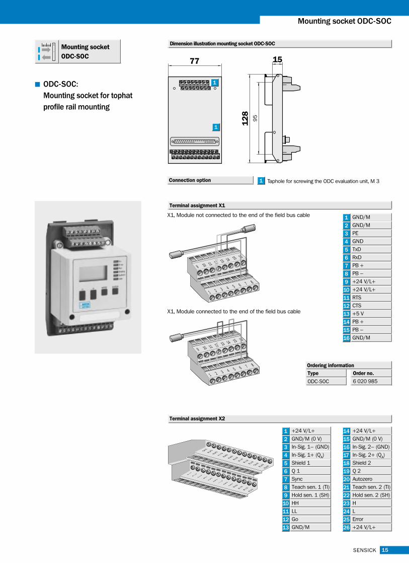
Mounting socket ODC-SOC
Terminal assignment X1
X1, Module not connected to the end of the field bus cable
1216
1 2 3 4 5 6 7 8
9 10 11 13 14 15
X1, Module connected to the end of the field bus cable
1216
1 2 3 4 5 6 7 8
9 10 11 13 14 15
1
2
3
4
5
6
7
8
9
10
11
12
13
14
15
16
1 2 3
23
4 5
161514
131211109876
25 2624
172221201918
12
89
5
1577
Taphole for screwing the ODC evaluation unit, M 31
1
1
Connection option
+24 V/L+
GND/M (0 V)
In-Sig. 1– (GND)
In-Sig. 1+ (QA)
Shield 1
Q 1
Sync
Teach sen. 1 (TI)
Hold sen. 1 (SH)
HH
LL
Go
GND/M
Ordering information
Type
ODC-SOC
Order no.
6 020 985
ODC-SOC:
Mounting socket for tophat
profile rail mounting
GND/M
GND/M
PE
GND
TxD
RxD
PB +
PB –
+24 V/L+
+24 V/L+
RTS
CTS
+5 V
PB +
PB –
GND/M
+24 V/L+
GND/M (0 V)
In-Sig. 2– (GND)
In-Sig. 2+ (QA)
Shield 2
Q 2
Autozero
Teach sen. 2 (TI)
Hold sen. 2 (SH)
H
L
Error
+24 V/L+
Mounting socket ODC-SOC
Terminal assignment X2
Dimension illustration mounting socket ODC-SOC

Your contact:
A u s t r a l i aPhone +61 3 94 97 41 00
0 08 33 48 02 – toll freeFax +61 3 94 97 11 87
A u s t r i aPhone +43 2 23 66 22 88-0Fax +43 2 23 66 22 88-5
B e l g i u m / L u x e m b o u r gPhone +32 24 66 55 66Fax +32 24 63 35 07
B r a z i lPhone +55 11 55 61 26 83Fax +55 11 55 35 41 53
C h i n a / H o n g K o n gPhone +8 52 27 63 69 66Fax +8 52 27 63 63 11
C z e c h R e p u b l i cPhone +42 02 578 10 561Fax +42 02 578 10 559
D e n m a r kPhone +45 45 82 64 00Fax +45 45 82 64 01
F i n l a n dPhone +3 58 9-7 28 85 00Fax +3 58 9-72 88 50 55
F r a n c ePhone +33 1-64 62 35 00Fax +33 1-64 62 35 77
G e r m a n yPhone +49 2 11 53 01-0Fax +49 2 11 53 01-1 00
G r e a t B r i t a i nPhone +44 17 27-83 11 21Fax +44 17 27-85 67 67
I t a l yPhone +39 02-92 14 20 62Fax +39 02-92 14 20 67
J a p a nPhone +813 33 58-13 41Fax +813 33 58-05 86
N e t h e r l a n d sPhone +31 3 02 29 25 44Fax +31 3 02 29 39 94
N o r w a yPhone +47 67 81 50-0Fax +47 67 81 50-01
P o l a n dPhone +48 22 8 37 40 50Fax +48 22 8 37 43 88
S i n g a p o r ePhone +65 7 44 37 32Fax +65 8 41 77 47
S p a i nPhone +34 9 34 80 31 00Fax +34 9 34 73 44 69
S w e d e nPhone +46 8-6 80 64 50Fax +46 8-7 10 18 75
S w i t z e r l a n dPhone +41 4 16 19 29 39Fax +41 4 16 19 29 21
Ta i w a nPhone +88 62 23 65 62 92Fax +88 62 23 68 73 97
U S APhone +1 (952) 9 41-67 80Fax +1 (952) 9 41-92 87
Representatives and agenciesin all major industrial nations.
SICK AG • Automatisierungstechnik • Sebastian-Kneipp-Straße 1 • D-79183 WaldkirchPhone +49 76 81 2 02-0 • Fax +49 76 81 2 02-36 09 • www.sick.de8
00
8 7
77/1
7-0
5-0
1 •
HJS
/FD
• P
rinte
d in
Ger
man
y (0
5.0
1) •
We
rese
rve
the
right
to m
ake
chan
ges