displacement-based seismic design of masonry shear wall ... · pdf filedisplacement-based...
TRANSCRIPT
Displacement-based Seismic Design of Masonry Shear Wall Structures
Farhad Ahmadi, Ph.D., P.E., S.E.Research and DevelopmentWalter P Moore and Associates
Big Island of Hawaii, HI December 4, 2014
2 of 24
important points of this presentation
• current seismic design does not always work well for shear-wall structures
• proposed displacement-based seismic design works well for shear wall structures▫ produces structures that behave reliably in
strong earthquakes▫ more consistent and more transparent than
current seismic design
3 of 24
project participants
Prof. Richard KlingnerJaime Hernandez Barredo
Prof. Benson ShingAndreas StavridisMarios Mavros
Prof. David McLeanJacob ShermanChristina DuncanWill Cyrier
4 of 24
contents of presentation
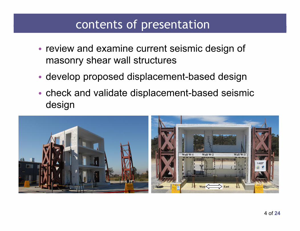
• review and examine current seismic design of masonry shear wall structures
• develop proposed displacement-based design • check and validate displacement-based seismic
design
Wall W-1 Wall W-2 Wall W-3
West East
5 of 24
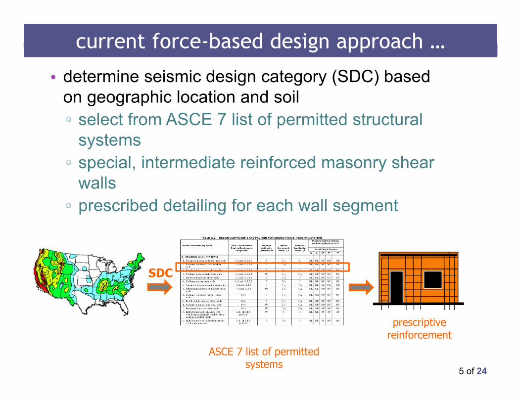
current force-based design approach …
• determine seismic design category (SDC) based on geographic location and soil▫ select from ASCE 7 list of permitted structural
systems ▫ special, intermediate reinforced masonry shear
walls▫ prescribed detailing for each wall segment
SDC
ASCE 7 list of permitted systems
prescriptive reinforcement
6 of 24
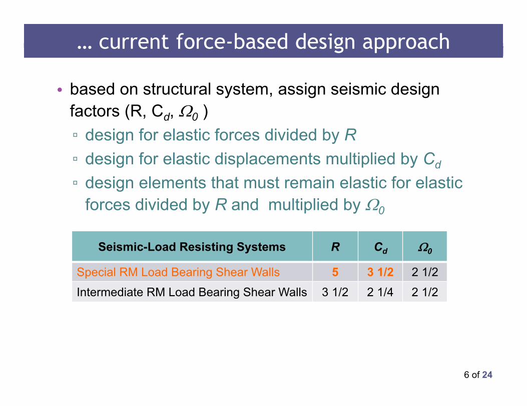
… current force-based design approach
• based on structural system, assign seismic design factors (R, Cd, 0 )▫ design for elastic forces divided by R▫ design for elastic displacements multiplied by Cd▫ design elements that must remain elastic for elastic
forces divided by R and multiplied by 0
Seismic-Load Resisting Systems R Cd 0
Special RM Load Bearing Shear Walls 5 3 1/2 2 1/2
Intermediate RM Load Bearing Shear Walls 3 1/2 2 1/4 2 1/2
7 of 24
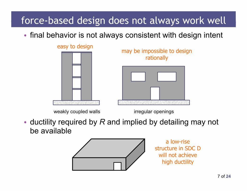
• final behavior is not always consistent with design intent
• ductility required by R and implied by detailing may not be available
force-based design does not always work well
irregular openings
may be impossible to design rationally
easy to design
weakly coupled walls
a low-rise structure in SDC D
will not achieve high ductility
8 of 24
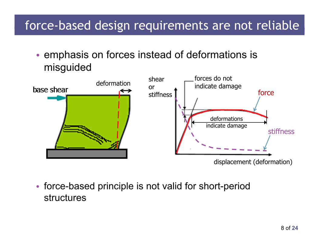
• emphasis on forces instead of deformations is misguided
• force-based principle is not valid for short-period structures
force-based design requirements are not reliable
shearorstiffness
forces do not indicate damage
displacement (deformation)
deformation
deformations indicate damage
force
stiffness
9 of 24
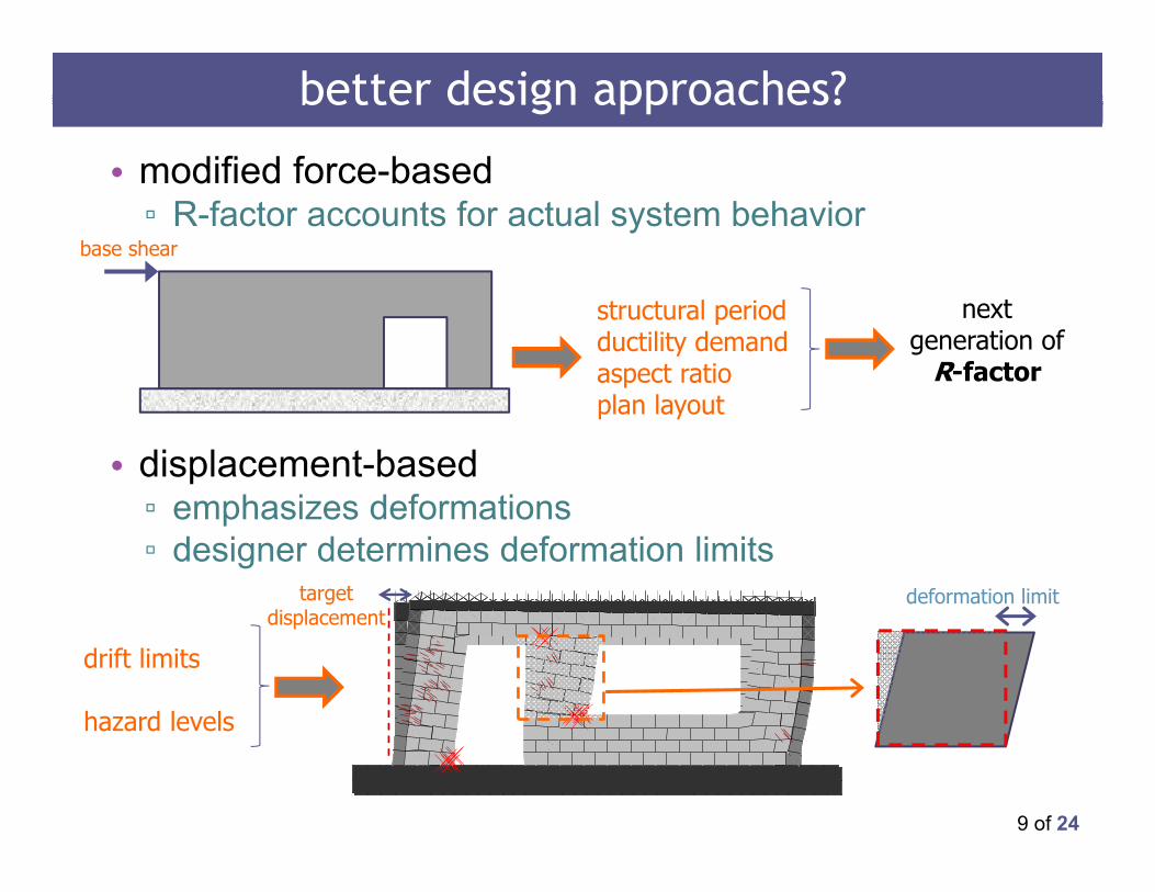
better design approaches?
• modified force-based▫ R-factor accounts for actual system behavior
• displacement-based ▫ emphasizes deformations ▫ designer determines deformation limits
structural periodductility demandaspect ratioplan layout
next generation of
R-factor
drift limits
hazard levels
deformation limittarget displacement
base shear
10 of 24
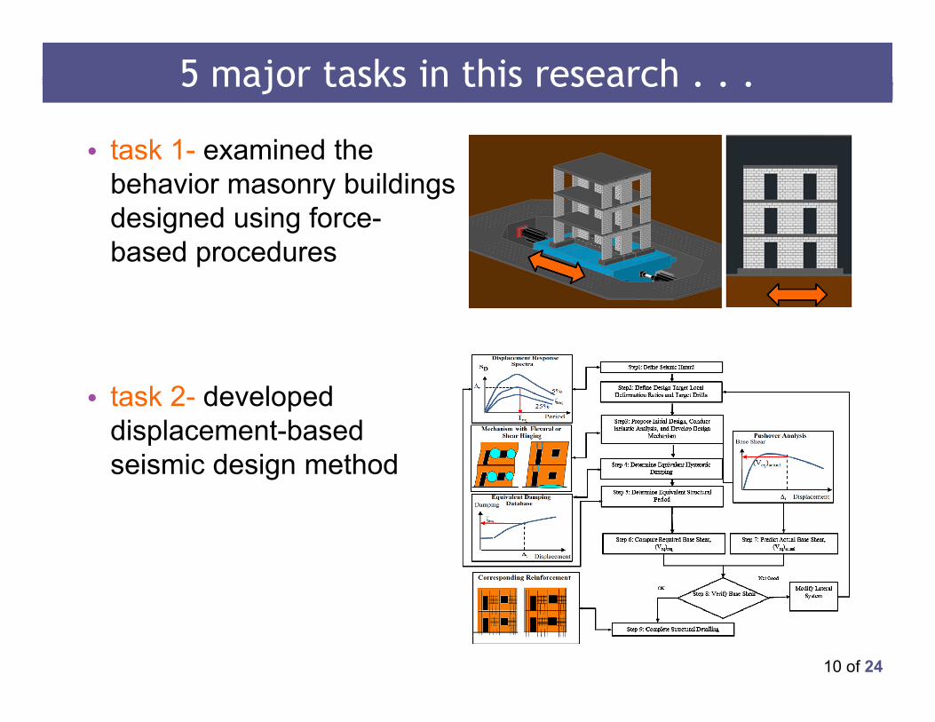
5 major tasks in this research . . .
• task 1- examined the behavior masonry buildings designed using force-based procedures
• task 2- developed displacement-based seismic design method
11 of 24
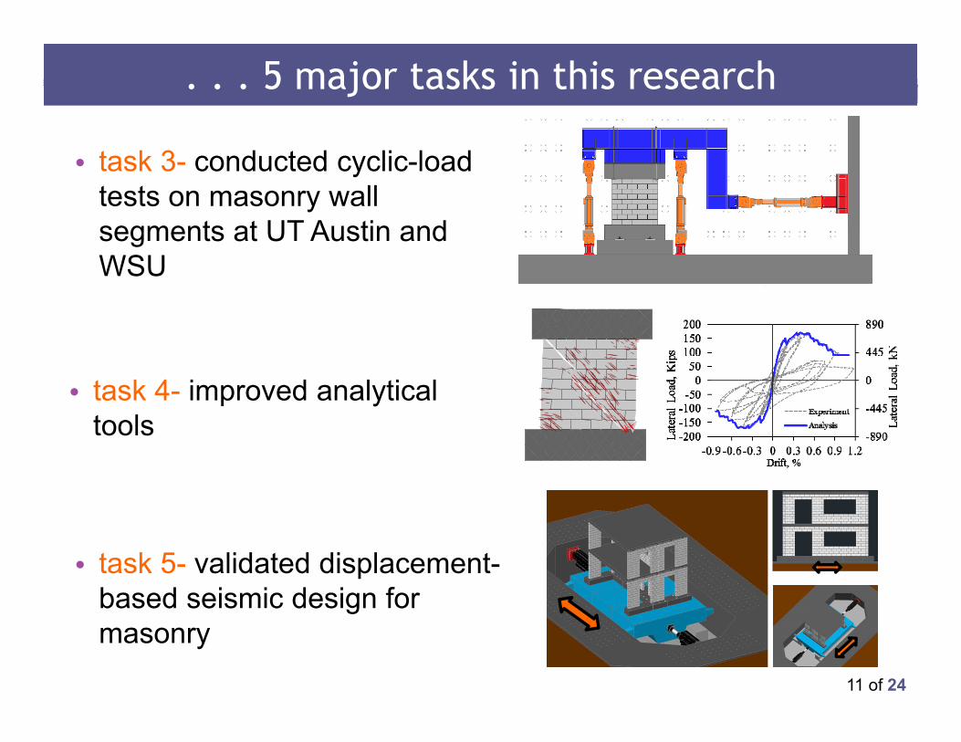
. . . 5 major tasks in this research
• task 3- conducted cyclic-load tests on masonry wall segments at UT Austin and WSU
• task 5- validated displacement-based seismic design for masonry
• task 4- improved analytical tools
12 of 24
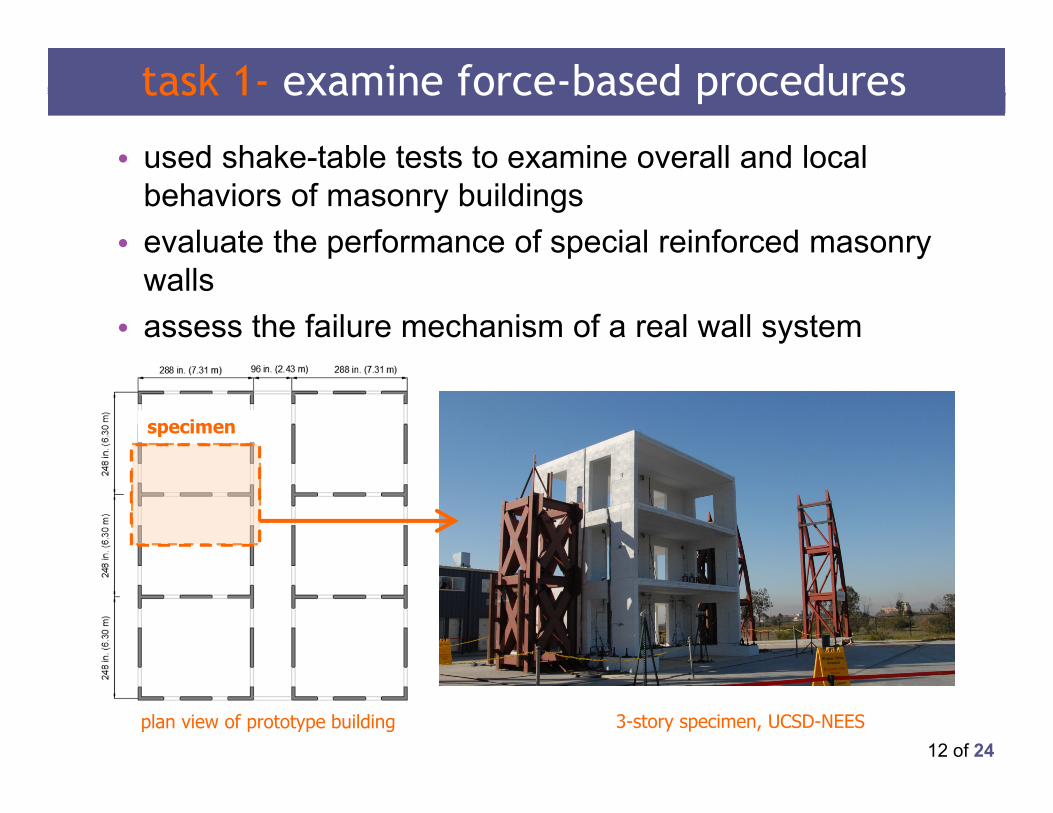
task 1- examine force-based procedures
• used shake-table tests to examine overall and local behaviors of masonry buildings
• evaluate the performance of special reinforced masonry walls
• assess the failure mechanism of a real wall system
specimen
plan view of prototype building 3-story specimen, UCSD-NEES
13 of 24
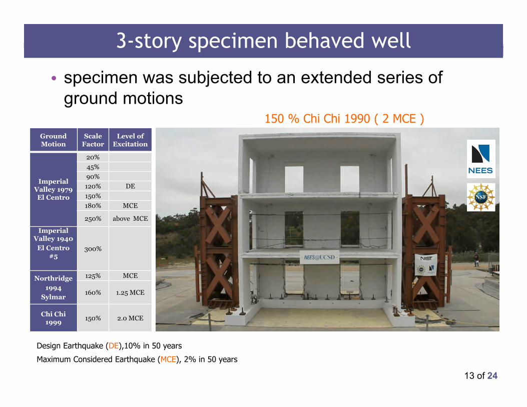
3-story specimen behaved well
• specimen was subjected to an extended series of ground motions
Ground Motion
Scale Factor
Level of Excitation
Imperial Valley 1979 El Centro
20%45%90%120% DE 150%180% MCE
250% above MCE
Imperial Valley 1940
El Centro #5
300%
Northridge1994
Sylmar
125% MCE
160% 1.25 MCE
Chi Chi1999 150% 2.0 MCE
150 % Chi Chi 1990 ( 2 MCE )
Design Earthquake (DE),10% in 50 years
Maximum Considered Earthquake (MCE), 2% in 50 years
14 of 24
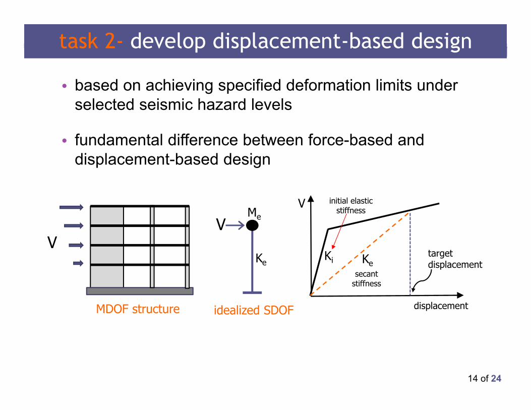
• based on achieving specified deformation limits under selected seismic hazard levels
• fundamental difference between force-based and displacement-based design
task 2- develop displacement-based design
VV
Me
Ke
displacement
V
KeKi
target displacement
initial elastic stiffness
secant stiffness
idealized SDOFMDOF structure
15 of 24
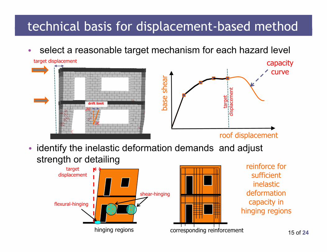
• select a reasonable target mechanism for each hazard level
• identify the inelastic deformation demands and adjust strength or detailing
roof displacement
base
she
ar
capacity curve
technical basis for displacement-based method
drift limit
target displacement
targ
et
disp
lace
men
thinging regions
target displacement
shear-hinging
flexural-hinging
corresponding reinforcement
reinforce for sufficient inelastic
deformation capacity in
hinging regions
16 of 24
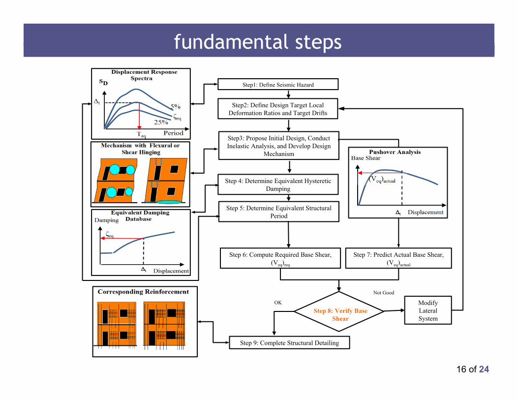
fundamental st
Step 4: Determine Equivalent Hysteretic Damping
Step3: Propose Initial Design, Conduct Inelastic Analysis, and Develop Design
Mechanism
Step 5: Determine Equivalent Structural Period
Step 6: Compute Required Base Shear, (Veq)req
Step 7: Predict Actual Base Shear, (Veq)actual
Modify Lateral System
Not Good
OK
Step 9: Complete Structural Detailing
Step2: Define Design Target Local Deformation Ratios and Target Drifts
Step1: Define Seismic Hazard
Step 8: Verify Base Shear
fundamental steps
17 of 24
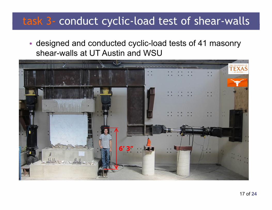
task 3- conduct cyclic-load test of shear-walls
• designed and conducted cyclic-load tests of 41 masonry shear-walls at UT Austin and WSU
▫ test different levels of prescriptive detailing, axial loads, boundary conditions, and aspect ratios
▫ refine inelastic analytical models ▫ find deformation limits
cantilever walls fixed-fixed walls
P/2 P/2
V
VP
18 of 24
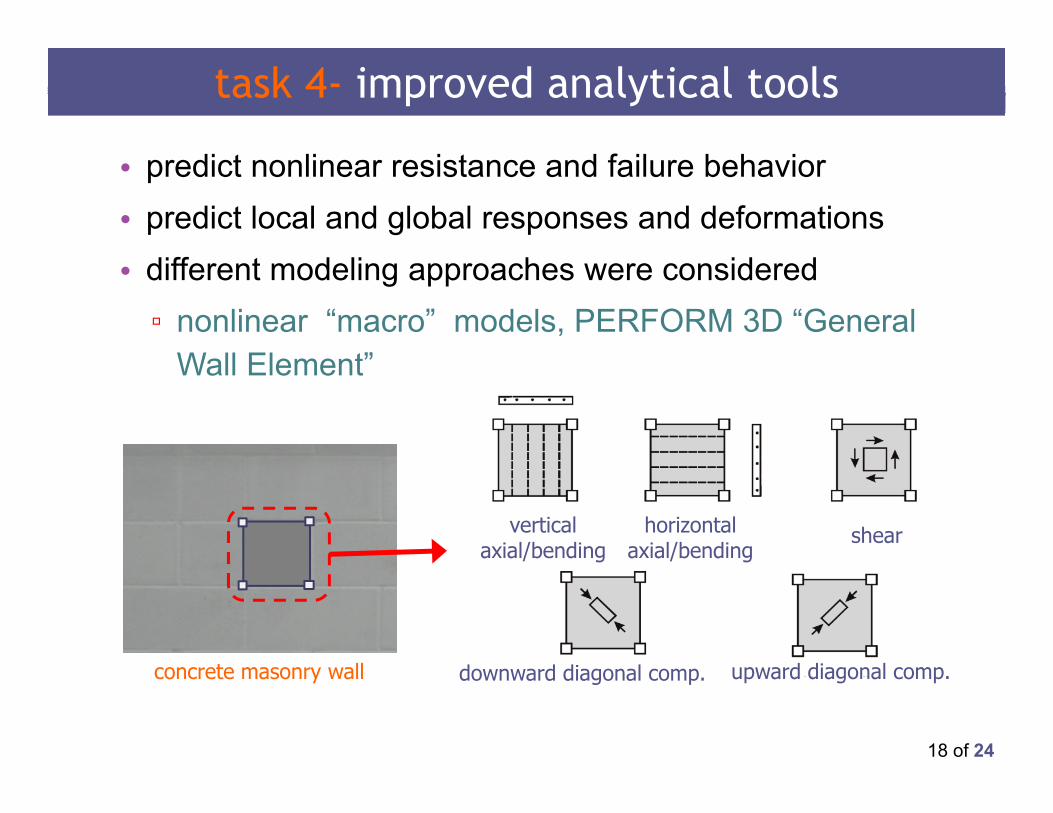
task 4- improved analytical tools
• predict nonlinear resistance and failure behavior • predict local and global responses and deformations• different modeling approaches were considered▫ nonlinear “macro” models, PERFORM 3D “General
Wall Element”
vertical axial/bending
horizontal axial/bending
shear
downward diagonal comp. upward diagonal comp.concrete masonry wall
19 of 24
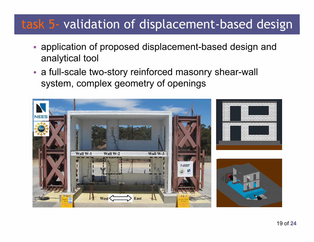
task 5- validation of displacement-based design
• application of proposed displacement-based design and analytical tool
• a full-scale two-story reinforced masonry shear-wall system, complex geometry of openings
Wall W-1 Wall W-2 Wall W-3
West East
20 of 24
select seismic hazard levels and target drifts
seismic hazard Level damage state
deformation limits corresponding inter-story drift
ratiosflexure-controlledwall segments
shear-controlled walls segments
Design Earthquake (DE )
Safety DamageState 0.8 % 0.5 % 0.3 %
MaximumConsidered
Earthquake (MCE)
Collapse Damage State 1.5 % 1.0 % 0.6 %
flexure-controlled
shear-controlled
21 of 24
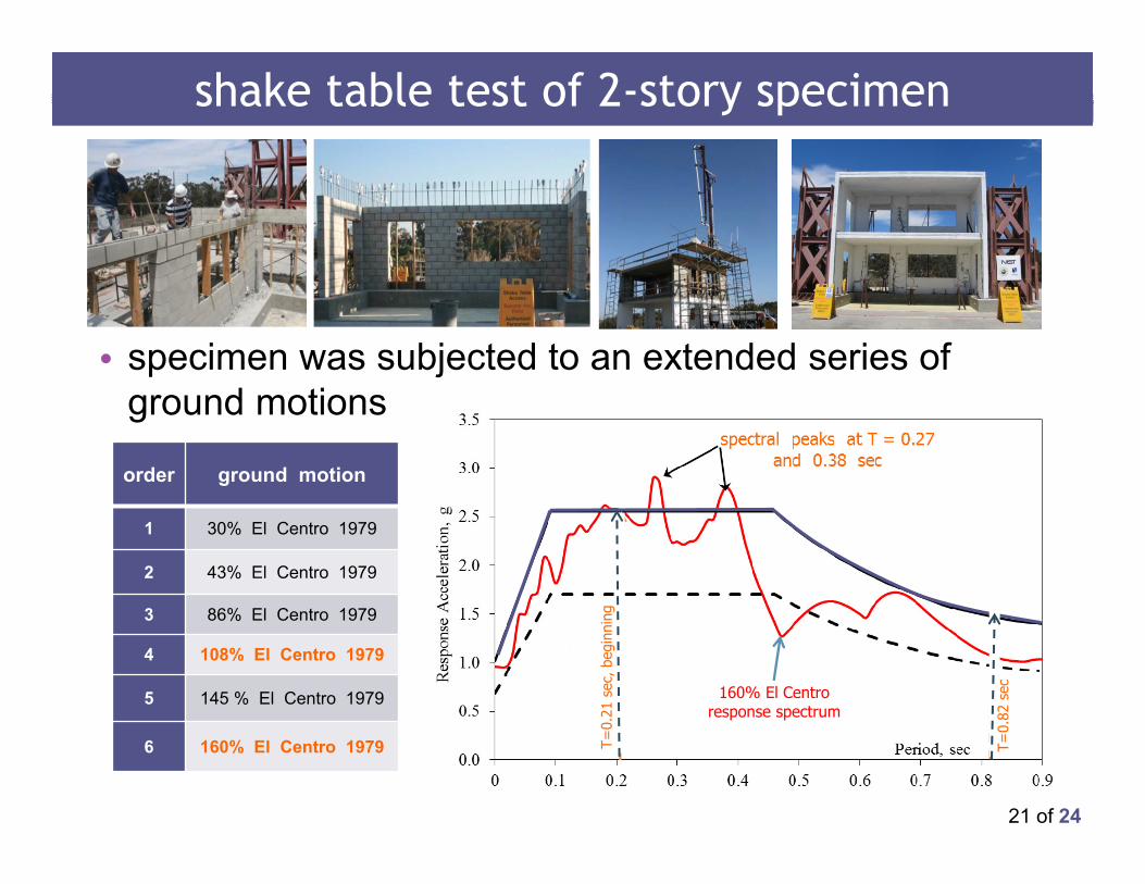
shake table test of 2-story specimen
• specimen was subjected to an extended series of ground motions
order ground motion
1 30% El Centro 1979
2 43% El Centro 1979
3 86% El Centro 1979
4 108% El Centro 1979
5 145 % El Centro 1979
6 160% El Centro 1979
160% El Centro response spectrum
T=0.
21 s
ec, b
egin
ning
T=0.
82 s
ec
22 of 24
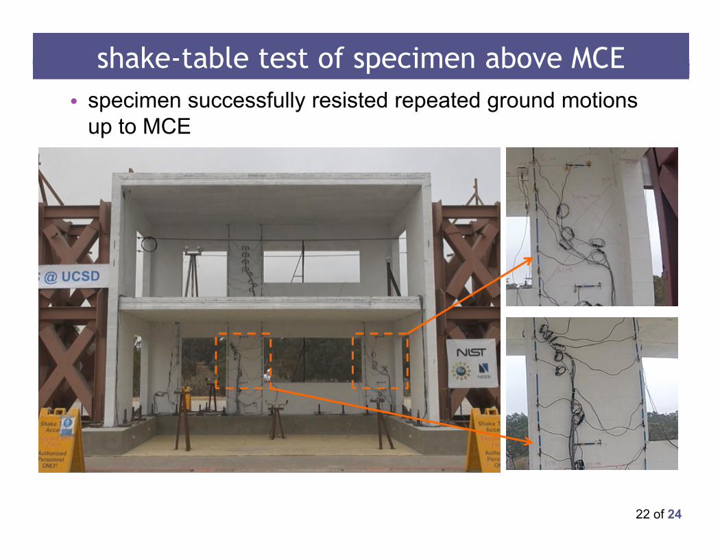
shake-table test of specimen above MCE• specimen successfully resisted repeated ground motions
up to MCE
23 of 24
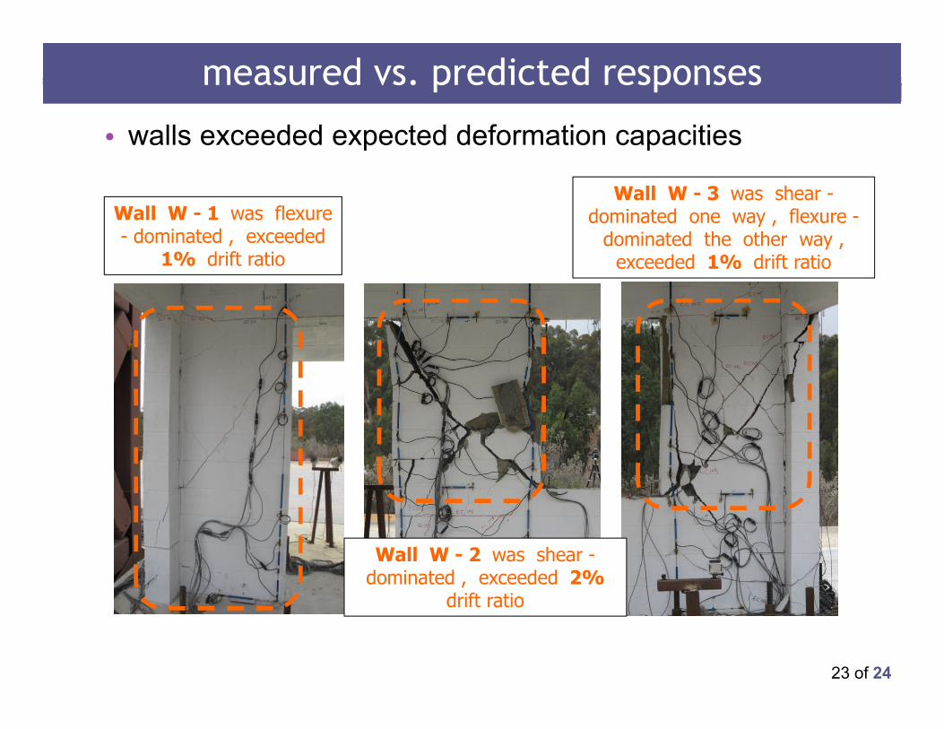
Wall W - 2 was shear -dominated , exceeded 2%
drift ratio
Wall W - 3 was shear -dominated one way , flexure -
dominated the other way , exceeded 1% drift ratio
Wall W - 1 was flexure - dominated , exceeded
1% drift ratio
• walls exceeded expected deformation capacities
measured vs. predicted responses
24 of 24
important points of this presentation
• current force-based seismic design does not always work well for reinforced masonry shear-wall structures
• proposed displacement-based seismic design works for masonry shear wall structures▫ it produces structures that behave reliably in
strong earthquakes▫ it is more consistent and more transparent than
current force-based seismic design