displacement-based seismic design of … · 1 displacement-based seismic design of damped braces...
TRANSCRIPT

1
DISPLACEMENT-BASED SEISMIC DESIGN OF DAMPED BRACES FOR RETROFITTING IN-ELEVATION IRREGULAR
FRAMED STRUCTURES
Fabio MAZZA1, Mirko MAZZA2 and Alfonso VULCANO3
ABSTRACT
A Displacement-Based Design procedure is proposed for proportioning hysteretic damped braces (HYDBs) in order to attain, for a specific level of seismic intensity, a designated performance level of a reinforced concrete (r.c.) in-elevation irregular framed building which has to be retrofitted. To check the effectiveness and reliability of the design procedure, a numerical investigation is carried out with reference to a six-storey r.c. framed building, which, primarily designed according to an old Italian seismic code (1996) for a medium-risk zone, has to be retrofitted by insertion of HYDBs for attaining performance levels imposed by the current Italian code (NTC08) in a high-risk zone. To simulate a vertical irregularity, a change of use of the first two floors, from a residential use into office, is also supposed; moreover, masonry infill walls, regularly distributed along the perimeter, are substituted with glass windows on these floors. Nonlinear dynamic analyses of unbraced (UF), infilled (IF) and damped braced infilled (DBIF) frames are carried out considering sets of artificially generated and real ground motions, whose response spectra match those adopted by NTC08 for different performance levels. To this end, r.c. frame members are idealized by a two-component model, assuming a bilinear moment-curvature law whose ultimate bending moment depends on the axial load, while the response of an HYDB is idealized by a bilinear law, providing that the buckling be prevented. Finally, masonry infills are represented as equivalent diagonal struts, only in compression, with an elastic-brittle linear law.
INTRODUCTION
Vertical irregularities in buildings are now having a lot of interest in seismic research area, because many structures are designed with significant change in stiffness, strength and mass distribution in-elevation due to architectural views and functional reasons. Specifically, low- and medium-rise reinforced concrete (r.c.) framed buildings are often built with irregularities in elevation due to soft-storeys, unsymmetrical layout of infill walls, setbacks. However, recent earthquakes confirmed that r.c. buildings having such irregularities were often severely damaged. Among the techniques of passive control that have had real application for the seismic retrofitting of framed structures, in the last two decades that based on the dissipation of a large portion of the energy transmitted by the earthquake to the structure can be considered very effective. Currently a wide variety of energy
1 Researcher, Dipartimento di Ingegneria Civile, Università della Calabria, Rende (Cosenza), Italy, [email protected] 2 Research fellow, Dipartimento di Ingegneria Civile, Università della Calabria, Rende (Cosenza), Italy, mirko. [email protected] 3 Full professor, Dipartimento di Ingegneria Civile, Università della Calabria, Rende (Cosenza), Italy, [email protected]

2
dissipating devices is available for the passive control of vibrations (e.g. see Christopoulos and Filiatrault, 2006). The extra cost of the damped braces, constituted of steel braces (e.g. single diagonal, cross or chevron braces, toggle-brace and scissor-jack) equipped with suitable devices (e.g. friction (FR), hysteretic (HY), viscous (VS) or viscoelastic (VE) dampers), is largely recovered because a more easy and less expensive solution is obtained, in comparison with other retrofitting techniques, for the vulnerability problems resulting from in-elevation irregularities.
For a widespread application of supplemental dampers, comprehensive analysis, design and testing guidelines should be available. New seismic codes (e.g. European code, EC8 2003, and Italian code, NTC08 2008) allow for the use of damped braces for the seismic retrofitting of framed buildings, while only few codes provide simplified criteria for their design (e.g. U.S.A. code, FEMA 356 2000). Moreover, the application of an energy dissipating bracing system for seismic retrofitting is more difficult than that involved in the design of new structures, because the optimization of the system properties is needed depending on the uncertainty in structural and damping properties of the existing structure (e.g. Lavan and Avishur, 2013). According to the new philosophy of Performance-Based-Design (PBD), a design objective is obtained coupling a performance level with a specific level of ground motion (Priestley et al., 2007). On the basis of the PBD several simplified nonlinear methods have been proposed, combining the nonlinear static (pushover) analysis of the multi-degree-of-freedom model of the actual structure with the response spectrum analysis of an equivalent single-degree-of-freedom system (Fajfar, 1999). More specifically, two alternative approaches have been followed: (a) the Force-Based Design (FBD) approach combined with required deformation target verification (e.g. see Ponzo et al., 2012, or Kim et al., 2003, referring to HY or VS dampers, respectively); (b) the Displacement-Based Design (DBD) approach, in which the design starts from a target deformation (e.g. see Mazza and Vulcano, 2008, 2013, in the case of HY and VE dampers) of an equivalent elastic (linear) system with effective properties (i.e. secant stiffness and equivalent viscous damping).
However, further studies are needed to generalize and validate the design procedure in case of framed buildings with vertical irregularities. In the present work, the criteria followed in elevation are aimed to obtain a damped braced structure globally regular with regard to stiffness and strength. The stiffness distribution of the HYDBs is evaluated consistently with a constant value of the drift ratio of the damped braced frame along the building height. Moreover, the strength distribution of the HYDBs is assumed so that their activation happens at all storeys, at the same time and before the attainment of the shear resistance of the infilled framed structure.
DISPLACEMENT-BASED DESIGN OF HYSTERETIC DAMPED BRACES
A Displacement-Based Design (DBD) procedure proposed by Mazza and Vulcano (2008), which aims to proportion hysteretic damped braces (HYDBs) to attain a designated performance level of an existing r.c. regular framed structure (for a specific level of seismic intensity), is extended to in-elevation irregular framed buildings. The main steps of the proposed design procedure are summarized below. 1. Pushover analysis of the unbraced frame and definition of an equivalent single degree of freedom (ESDOF) system to evaluate the equivalent viscous damping due to hysteresis
Nonlinear static (pushover) analysis of the unbraced frame (whose properties are supposed as given), under constant gravity loads and monotonically increasing horizontal loads, is carried out to obtain the base shear-top displacement (V(F)-d) curve (Figure 1a). For this purpose, the lowest capacity curve is selected among those corresponding to the most common lateral-load profiles: e.g. a "uniform" distribution, proportional to the floor masses (m1, m2, ...., mn); a “first-mode” distribution, obtained multiplying the first-mode components (1, 2, .., n) by the corresponding floor masses.
The selected V(F)-d curve can be idealized as bilinear and the original frame can be represented by an ESDOF system (Fajfar, 1999) characterized by a bilinear curve (V*-d*), with a yield displacement dy
(F) and a stiffness hardening ratio rF, derived from the idealized V(F)-d curve (see Figure 1b). Once the displacement (dp) and the corresponding base shear (Vp
(F)) are settled, for a given

F. Mazza, M. Mazza and A. Vulcano 3
performance level, the ductility
(F)F p yμ = d d (1)
and the equivalent (secant) stiffness
(F) (F)e p pK =V d (2)
can be evaluated for the frame. From the Jacobsen approach (Jacobsen, 1930), the equivalent viscous damping due to hysteresis
of the framed structure, F(h), can be calculated:
(h)F F F F F F Fξ (%)=κ 63.7 μ -1 1-r μ +μ r μ -1 (3)
where F and rF have been defined above. The parameter , which accounts for the mechanical degradation, depends on the structural type (e.g. κ can be assumed as equal to 1/3 in the case of poor structural behaviour (ATC, 1996). It is worth noting that F
(h) is assumed as equal to zero when dp≤dy
(F). 2. Equivalent viscous damping due to hysteresis of the damped braces
If the constitutive law of the equivalent damped brace is idealized as bilinear (see Figure 1c), the corresponding viscous damping, DB=DB(DB, rDB), can be evaluated as
DB DB DB DB DB DB DBξ (%)=63.7 μ -1 1-r μ +μ r μ -1 (4)
where DB, and rDB are, respectively, the ductility demand and the stiffness hardening ratio of the equivalent damped brace.
The ductility demand of the equivalent damped brace, DB, can be evaluated as
* *
DB D D D Dμ = 1+ μ -1 1+r K 1+K (5)
D being the damper ductility, whose value should be selected to be compatible with the deformation capacity of the damper itself, rD the stiffness hardening ratio of the damper and K*
D(=KD/KB) the stiffness ratio reasonably assumed as rather less than 1.
The stiffness of a damped brace (KDB) can be expressed as for an in-series system depending on the brace stiffness (KB) and the elastic stiffness of the damper (KD):
DB B DK = 1 1 K 1 K (6)
The stiffness hardening ratio of the damped brace, rDB, can be expressed as
* *
DB B D B D D D D D Dr = 1 K +1 K 1 K +1 r K =r 1+K 1+r K (7)
where KB, KD, rD and K*D have been defined above.
3. Equivalent viscous damping of the frame with damped braces
Assuming a suitable value of the elastic viscous damping for the framed structure (e.g. as commonly done, ξV=5%), the equivalent viscous damping of the in-parallel system comprised of framed structure (F) and damped braces (DBs) is
(h) (F) (DB) (F) (DB)F p DB p p pe V(%) ξξ V +ξ V V +V+ξ (8)
where F(h) and DB have been calculated in steps 1 and 2, respectively, Vp
(F) has been defined above and Vp
(DB) represents the base-shear contribution due to the damped braces of the damped braced frame at the performance point. Then, with reference to the displacement spectrum for e, the effective period (Te) of the DBF can be evaluated as the period corresponding to the performance displacement dp.

4
4. Effective stiffness of the equivalent damped brace
Once the mass of the ESDOF system, me=∑mii, is calculated, the effective stiffness of DBF (Ke) and the effective stiffness required by the damped braces (Ke
(DB)) can be evaluated as
2 2e e eΚ =4π m T (9)
(DB) (F)e e eK =K K (10)
5. Effective strength properties of the equivalent damped brace
Because the base shear-displacement curve representing the response of the damped braces of the actual structure (V(DB)-d) has been idealized as bilinear, the base-shear contributions of the damped braces at the performance and yielding points (Vp
(DB) and Vy(DB), respectively) can be calculated:
(DB) (DB)p e pV =K d (11)
(DB) (DB)y p DB DBV =V 1+r μ -1 (12)
It is worth mentioning that the equivalent viscous damping expressed by Eq. (8) depends on the base-shear Vp
(DB), which is initially unknown. As a consequence, an iterative procedure is needed for the solution of Eqs. (8)(12). 6a. Design of the hysteretic damped braces of the damped braced frame for retrofitting in-elevation regular framed structure
Finally, the distribution of the lateral loads carried by the damped braces at the yielding point (dy
(DB)) can be assumed. Once the shear at a generic storey is calculated (Figure 1d)
n nj j(DB) (DB) (DB)
yi yj ynj=i j=i
k kk=1
mV = F V
m
(13)
the quantities which are needed for designing the damped brace at that storey can be determined. In particular, for a diagonal brace with HYD (Figure 1d) can be calculate the yield-load
(DB)yi yi iN =V 2cosα (14)
and the elastic stiffness of the damped brace (along the brace direction)
(DB)yi(DB)
i (DB) 2i i-1 y i
V 1K =
d cosα (15)
6b. Design of the hysteretic damped braces of the damped braced frame for retrofitting in-elevation irregular framed structure
The criteria followed for an in-elevation irregular infilled framed structure are aimed to obtain a damped braced structure globally regular with regard to stiffness and strength. For this purpose, an inverted-triangular (linear) first vibration mode (lin) and the corresponding shear forces (Vlin
(DBF)) of the damped braced frame are calculated
, .., , ..1 , .., , ..,
Tn nT (DBF)lin 1 6 i 6 lin j lin, j j lin, j n lin,n
j=1 j=i
= h h h h m m m V (16)
Then, the lateral stiffness of the damped braced frame (Ki(DBF)), consistently with a constant value of
the drift ratio (=interstorey drift (i)/height storey (hi)) at each storey (Figure 1d), can be evaluated assuming
(DBF)(DBF)
lin,ii 1(DBF) (DBF)1 lin,1 i
VK h, i=2,..,n
K V h (17)

F. Mazza, M. Mazza and A. Vulcano 5
while the lateral stiffness of the damped braces (Ki(DB)) can be obtained starting from the lateral
stiffness of the frame (Ki(F)) corresponding to i/hi(=const.):
(DB) (DBF) (F)i i iK K K , i=1,..,n (18)
Finally, to make comparable the structural solutions for in-elevation regular and irregular buildings, the sum of all the storey stiffnesses of the damped braces can be assumed the same for both cases
n n(DB) (DB)i i
i=1 i=1Regular Irregular
K K (19)
On the other hand, the strength distribution of the HYDBs is assumed so that their yielding shear force (V*
yi(DB)) is reached, at each storey, before the attainment of the ultimate values of frame
(Vui(F)) and infill (Vui
(I)) shear forces
; *(DB) (F) (I)yi ui uiV min V V , i=1,..,n (20)
Afterwards, the distribution law of the yielding shear force in the HYDBs is modified (Vyi(DB)) be
similar to that of the (elastic) shear force induced by the lateral loads corresponding to the inverted-triangular first vibration mode (Vdi
(DB)), so that their activation happens at the same time
(DB)V,min(DB) *(DB)
yi yi (DB)Vi
V V , i=1,..,n (21)
where
min
*(DB)yi(DB) (DB) (DB)
Vi V,min Vi(DB)di
V,
V (22a,b)
In this way, the shear ratio of the HYDBs, defined as the ratio between their actual shear (Vyi(DB)) and
the shear required by the analysis (Vdi(DB)), is constant along the building height.
(a) In-elevation unbraced frame (UF) (b) ESDOF of the framed structure (F)
(c) ESDOF of the damped braces (DBs) (d) In-elevation HYDBs in the damped braced frame (DBF) Figure 1. Quantities for designing hysteretic damped braces (HYDBs)
6
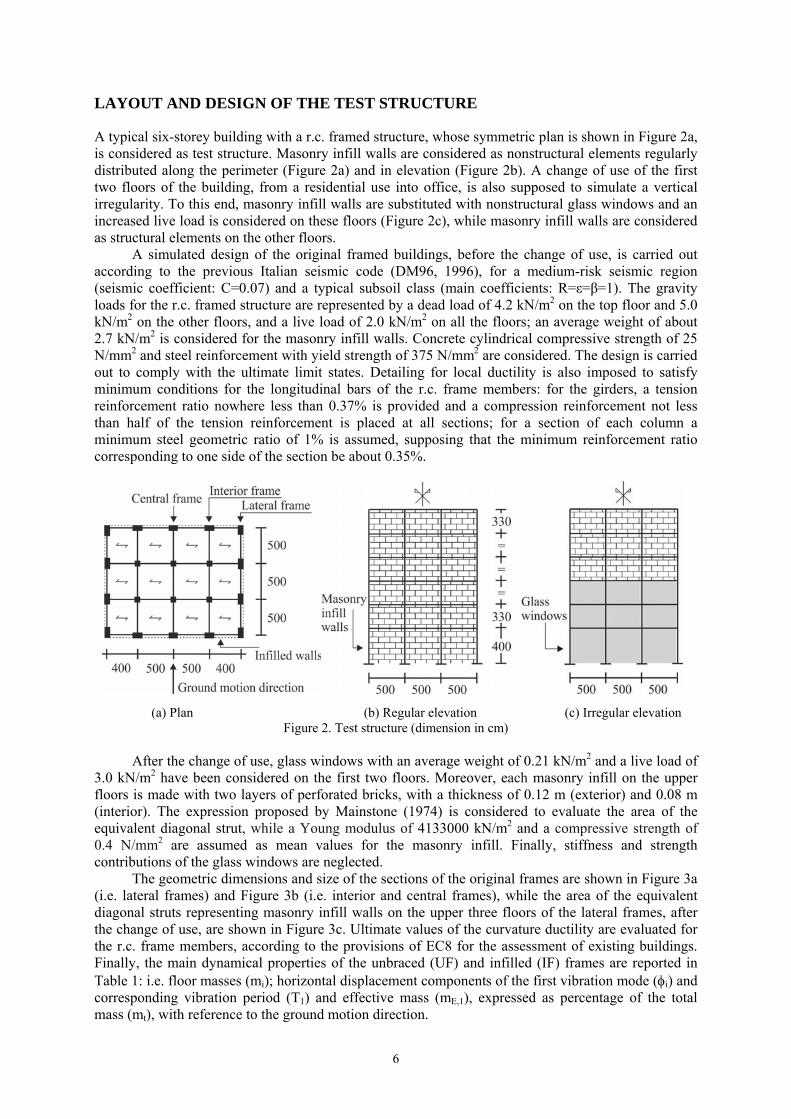
LAYOUT AND DESIGN OF THE TEST STRUCTURE
A typical six-storey building with a r.c. framed structure, whose symmetric plan is shown in Figure 2a, is considered as test structure. Masonry infill walls are considered as nonstructural elements regularly distributed along the perimeter (Figure 2a) and in elevation (Figure 2b). A change of use of the first two floors of the building, from a residential use into office, is also supposed to simulate a vertical irregularity. To this end, masonry infill walls are substituted with nonstructural glass windows and an increased live load is considered on these floors (Figure 2c), while masonry infill walls are considered as structural elements on the other floors.
A simulated design of the original framed buildings, before the change of use, is carried out according to the previous Italian seismic code (DM96, 1996), for a medium-risk seismic region (seismic coefficient: C=0.07) and a typical subsoil class (main coefficients: R=ε=β=1). The gravity loads for the r.c. framed structure are represented by a dead load of 4.2 kN/m2 on the top floor and 5.0 kN/m2 on the other floors, and a live load of 2.0 kN/m2 on all the floors; an average weight of about 2.7 kN/m2 is considered for the masonry infill walls. Concrete cylindrical compressive strength of 25 N/mm2 and steel reinforcement with yield strength of 375 N/mm2 are considered. The design is carried out to comply with the ultimate limit states. Detailing for local ductility is also imposed to satisfy minimum conditions for the longitudinal bars of the r.c. frame members: for the girders, a tension reinforcement ratio nowhere less than 0.37% is provided and a compression reinforcement not less than half of the tension reinforcement is placed at all sections; for a section of each column a minimum steel geometric ratio of 1% is assumed, supposing that the minimum reinforcement ratio corresponding to one side of the section be about 0.35%.
(a) Plan (b) Regular elevation (c) Irregular elevationFigure 2. Test structure (dimension in cm)
After the change of use, glass windows with an average weight of 0.21 kN/m2 and a live load of
3.0 kN/m2 have been considered on the first two floors. Moreover, each masonry infill on the upper floors is made with two layers of perforated bricks, with a thickness of 0.12 m (exterior) and 0.08 m (interior). The expression proposed by Mainstone (1974) is considered to evaluate the area of the equivalent diagonal strut, while a Young modulus of 4133000 kN/m2 and a compressive strength of 0.4 N/mm2 are assumed as mean values for the masonry infill. Finally, stiffness and strength contributions of the glass windows are neglected.
The geometric dimensions and size of the sections of the original frames are shown in Figure 3a (i.e. lateral frames) and Figure 3b (i.e. interior and central frames), while the area of the equivalent diagonal struts representing masonry infill walls on the upper three floors of the lateral frames, after the change of use, are shown in Figure 3c. Ultimate values of the curvature ductility are evaluated for the r.c. frame members, according to the provisions of EC8 for the assessment of existing buildings. Finally, the main dynamical properties of the unbraced (UF) and infilled (IF) frames are reported in Table 1: i.e. floor masses (mi); horizontal displacement components of the first vibration mode (i) and corresponding vibration period (T1) and effective mass (mE,1), expressed as percentage of the total mass (mt), with reference to the ground motion direction.

F. Mazza, M. Mazza and A. Vulcano 7
(a) Section of girders and columns for the lateral frames
(b) Section of girders and columns for the interior and central frames
(c) Area of equivalent diagonal struts for the lateral frames
Figure 3. Layout of the r.c. original framed building after the change of use (dimensions in cm)
Table 1. Dynamical properties of the original (UF and IF) and retrofitted (DBIF_R and DBIF_IR) structures
T1(UF)= 0.746s
mE,1(UF)= 75%mt
T1(IF)=0.602s
mE,1(IF)=89%mt
T1(DBIF_R)=0.203s
mE,1(DBIF_R)=70%mt
T1(DBIF_IR)=0.203s
mE,1(DBIF_IR)=70%mt
Storey m i(UF) (kNs2/m) i
(UF) m i(IF) (kNs2/m) i
(IF) i(DBIF_R) i
(DBIF_IR)6 171 1.00 171 1.00 1.00 1.00 5 245 0.86 245 1.00 0.86 0.88 4 257 0.64 257 1.00 0.64 0.70 3 264 0.43 249 0.94 0.43 0.52 2 285 0.29 271 0.60 0.29 0.29 1 301 0.14 268 0.30 0.14 0.15
To upgrade the test structure from a medium-risk up to a high-risk seismic region, diagonal steel
braces with hysteretic dampers (HYDs) are inserted at each storey (Figure 4a). More specifically, HYDBs with stiffness and strength properties equal to those of the masonry infills existing before the change of use are placed in the exterior bays of the lateral frames, only at the first three storeys (Figure 4b), where a pair of equivalent diagonal struts represent the masonry walls placed at the upper three storeys. Moreover, HYDBs are also placed in the exterior bays of the interior frames, at all storeys (Figure 4c), according to the criteria above discussed for in-elevation regular (i.e. DBIF_R) and irregular (i.e. DBIF_IR) structures. The main dynamical properties of the DBIF_R and DBIF_IR structures are reported in Table 1.
(a) Plan (b) Lateral frame with masonry infills and HYDBs
(c) Interior frame with HYDBs
Figure 4. Damped braced infilled structure (DBIF) The HYDBs in Figure 4c are designed according to the procedure described above, considering
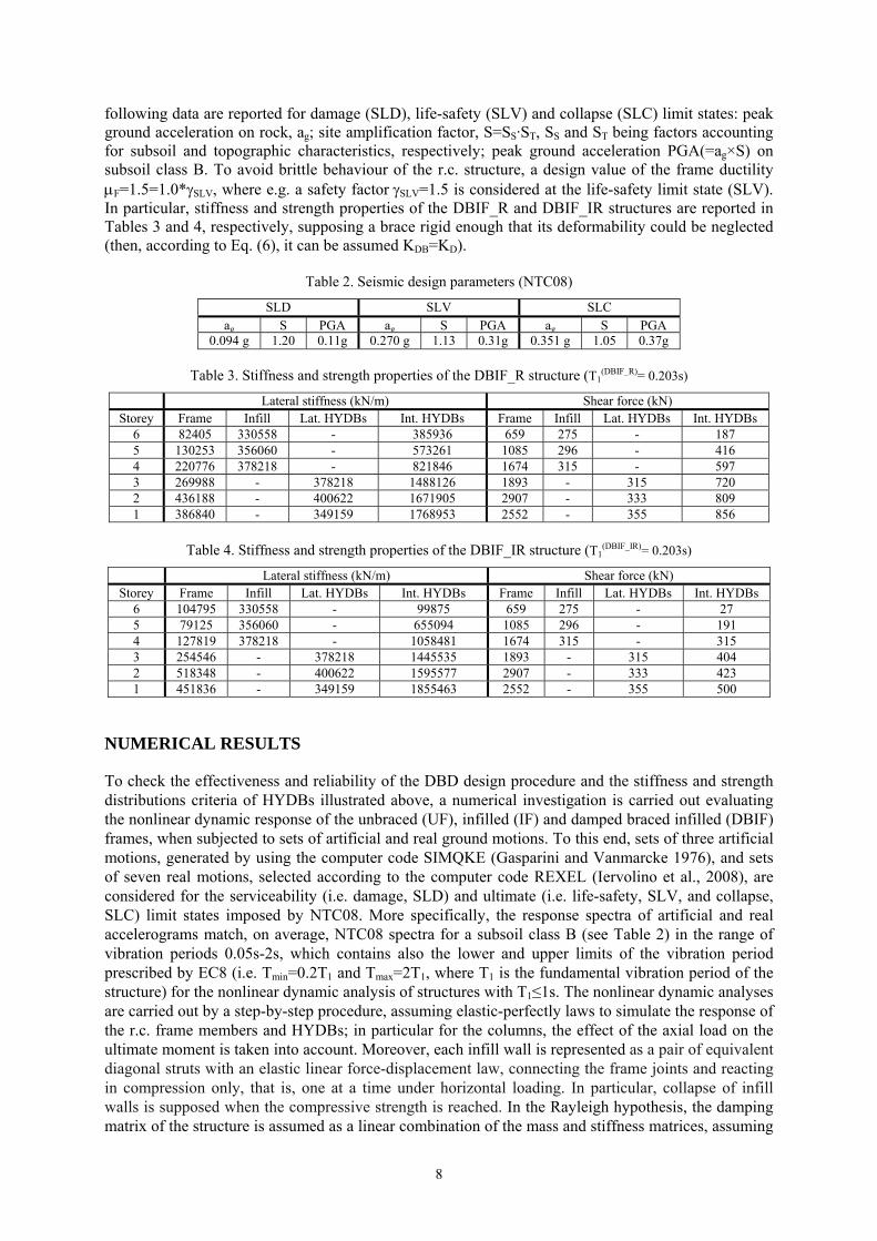
seismic loads provided by NTC08 for a high-risk seismic region and subsoil class B. In Table 2, the
8
following data are reported for damage (SLD), life-safety (SLV) and collapse (SLC) limit states: peak ground acceleration on rock, ag; site amplification factor, S=SS·ST, SS and ST being factors accounting for subsoil and topographic characteristics, respectively; peak ground acceleration PGA(=ag×S) on subsoil class B. To avoid brittle behaviour of the r.c. structure, a design value of the frame ductility F=1.5=1.0*SLV, where e.g. a safety factorSLV=1.5 is considered at the life-safety limit state (SLV). In particular, stiffness and strength properties of the DBIF_R and DBIF_IR structures are reported in Tables 3 and 4, respectively, supposing a brace rigid enough that its deformability could be neglected (then, according to Eq. (6), it can be assumed KDB=KD).
Table 2. Seismic design parameters (NTC08)
SLD SLV SLC ag S PGA ag S PGA ag S PGA
0.094 g 1.20 0.11g 0.270 g 1.13 0.31g 0.351 g 1.05 0.37g
Table 3. Stiffness and strength properties of the DBIF_R structure (T1(DBIF_R)= 0.203s)
Lateral stiffness (kN/m) Shear force (kN) Storey Frame Infill Lat. HYDBs Int. HYDBs Frame Infill Lat. HYDBs Int. HYDBs
6 82405 330558 - 385936 659 275 - 187 5 130253 356060 - 573261 1085 296 - 416 4 220776 378218 - 821846 1674 315 - 597 3 269988 - 378218 1488126 1893 - 315 720 2 436188 - 400622 1671905 2907 - 333 809 1 386840 - 349159 1768953 2552 - 355 856
Table 4. Stiffness and strength properties of the DBIF_IR structure (T1
(DBIF_IR)= 0.203s)
Lateral stiffness (kN/m) Shear force (kN) Storey Frame Infill Lat. HYDBs Int. HYDBs Frame Infill Lat. HYDBs Int. HYDBs
6 104795 330558 - 99875 659 275 - 27 5 79125 356060 - 655094 1085 296 - 191 4 127819 378218 - 1058481 1674 315 - 315 3 254546 - 378218 1445535 1893 - 315 404 2 518348 - 400622 1595577 2907 - 333 423 1 451836 - 349159 1855463 2552 - 355 500
NUMERICAL RESULTS
To check the effectiveness and reliability of the DBD design procedure and the stiffness and strength distributions criteria of HYDBs illustrated above, a numerical investigation is carried out evaluating the nonlinear dynamic response of the unbraced (UF), infilled (IF) and damped braced infilled (DBIF) frames, when subjected to sets of artificial and real ground motions. To this end, sets of three artificial motions, generated by using the computer code SIMQKE (Gasparini and Vanmarcke 1976), and sets of seven real motions, selected according to the computer code REXEL (Iervolino et al., 2008), are considered for the serviceability (i.e. damage, SLD) and ultimate (i.e. life-safety, SLV, and collapse, SLC) limit states imposed by NTC08. More specifically, the response spectra of artificial and real accelerograms match, on average, NTC08 spectra for a subsoil class B (see Table 2) in the range of vibration periods 0.05s-2s, which contains also the lower and upper limits of the vibration period prescribed by EC8 (i.e. Tmin=0.2T1 and Tmax=2T1, where T1 is the fundamental vibration period of the structure) for the nonlinear dynamic analysis of structures with T1≤1s. The nonlinear dynamic analyses are carried out by a step-by-step procedure, assuming elastic-perfectly laws to simulate the response of the r.c. frame members and HYDBs; in particular for the columns, the effect of the axial load on the ultimate moment is taken into account. Moreover, each infill wall is represented as a pair of equivalent diagonal struts with an elastic linear force-displacement law, connecting the frame joints and reacting in compression only, that is, one at a time under horizontal loading. In particular, collapse of infill walls is supposed when the compressive strength is reached. In the Rayleigh hypothesis, the damping matrix of the structure is assumed as a linear combination of the mass and stiffness matrices, assuming

F. Mazza, M. Mazza and A. Vulcano 9
a viscous damping ratio of 5% associated with the first and third vibration periods corresponding to higher-participation modes with prevailing contribution in the horizontal direction. All the following results are obtained as an average of those separately obtained for the sets of artificial or real motions corresponding to a limit state.
Firstly, the maximum ductility demand to girders and columns under the SLD, SLV and SLC sets of artificial ground motions are shown in Figures 5-7, along the building height, considering the original (i.e. UF and IF) and retrofitted (i.e. DBIF_R and DBIF_IR) structures. The ductility demand was calculated in terms of curvature, with reference to the two loading directions, assuming as yielding curvature for the columns the one corresponding to the axial force due to the gravity loads.
(a) (b) (c) Figure 5. Maximum ductility demand to r.c. frame members and drift ratio under SLD artificial motions,
assuming the minimum final instant of simulation for all structures (tmin=12s)
(a) (b) (c) Figure 6. Maximum ductility demand to r.c. frame members and drift ratio under SLV artificial motions,
assuming the minimum final instant of simulation for all structures (tmin=2.29s)
(a) (b) (c) Figure 7. Maximum ductility demand to r.c. frame members and HYDBs under SLC artificial motions,
assuming the minimum final instant of simulation for all structures (tmin=2.28s)

10
It is worth mentioning that the analyses were stopped, for all the examined cases, once the ultimate value imposed on the curvature ductility demand of the r.c. frame members was reached, but this happened at different instants of time (tmax). For this reason, the analyses were repeated assuming the minimum final instant of simulation (tmin) for all structures. As can be observed, comparable results have been obtained for the UF and IF structures, at all limit states. The insertion of HYDBs is effective in reducing the ductility demand of girders (Figures 5a, 6a and 7a), with similar curves for the DBIF_R and DBIF_IR structures. Moreover, columns of the second and third storeys exhibit a maximum ductility demand in the DBIF_R structure greater than that obtained in the UF and IF structures (Figures 5b, 6b and 7b). This kind of behaviour can be interpreted observing that the DBIF_R structure is characterized by values of the axial load in the columns higher than those in the original structures. Further results, omitted for the sake of brevity, have confirmed that the balanced compressive load is exceeded in some columns of the DBIF_R structure, at the lower three storeys, under SLV and SLC motions. Finally, for all the structures the maximum axial load is resulted much less than the ultimate compressive axial load and no tensile axial loads are found.
Then, to check the effectiveness of the design procedure for proportioning the HYDBs in such a way that an in-elevation regular framed structure is obtained and the hysteretic energy dissipated by the devices be as large as possible, the maximum values of the drift ratio at the SLD (Figure 5c) and SLV (Figure 6c) and ductility demand of the HYDBs at the SLC (Figure 7c) are plotted at each storey. It is interesting to note that the irregular distribution law of the drift ratio observed for the IF structure has been corrected in the DBIF_IR structure, in the quasi-elastic range, and in the DBIF_R structure, when plastic deformations occurred. As can be observed, the distribution law of the ductility demand is almost uniform and rather less than the design value (i.e. μD=10) for the DBIF_R structure, unlike what happens for the DBIF_IR structure where a large variability happens, with a mean ductility demand of about 13.2 at the SLC.
To better clarify the effectiveness of the HYDBs for controlling the local damage undergone by critical sections of the r.c. frame members, a time ratio t, defined as the final instant of simulation of each structure (i.e. tmax) divided by the total duration of the artificial motions (i.e. ttot=12s), is plotted in Figure 8. It is interesting to note that a value of t equal to 1 is obtained at the SLD, for the original and retrofitted structures (Figure 8a), and SLV, with the only exception of the UF structure (Figure 8b). On the other hand, the total duration of the artificial motions at the SLC is attained only for the DBIF_R and DBIF_IR structures (Figure 8c), while the interruption of the analysis happened in advance for the UF and IF structures.
(a) (b) (c) Figure 8. Time ratio (t) for all structures under SLD, SLV and SLC artificial motions
Ductility curves analogous to the previous ones are shown in Figure 9 with reference to the SLV
artificial motions, assuming the maximum final instant of simulation (tmax) for each structure. It should be noted that the response of the UF structure, characterized by a limited duration of the analysis (i.e. t=0.19), due to the attainment of the ultimate ductility demand in some r.c. frame members, is resulted generally better than that observed for the IF structure but the total duration of motion (i.e. t=1) is attained for this last. Moreover, the damage control of girders appears more effective using the DBIF_IR structure rather than the DBIF_R one, especially at the lower storeys, differently from that observed referring to the minimum final instant of simulation for all structures (see Figure 6a).

F. Mazza, M. Mazza and A. Vulcano 11
(a) (b) (c) Figure 9. Maximum ductility demand to r.c. frame members and HYDBs under SLV artificial motions,
assuming the maximum final instant of simulation (tmax) for each structure. Because of the structural symmetry and assuming the floor slabs to be infinitely rigid in their
own plane, the entire structure of Figure 2a is idealized by an equivalent plane frame (pseudo-three-dimensional model) along the considered horizontal ground motion direction. With reference to this structural configuration, in Figure 10 the spatial distribution of maximum ductility demand in the two perimeter (lateral) frames (Figures 10a,d), the two interior frames (Figures 10b,e) and the central frame (Figures 10c,f) is investigated. In particular, ductility demand to girders (Figures 10a,b,c) and columns (Figures 10d,e,f) are plotted under SLV real motions, assuming the minimum final instant of simulation (tmin) for all structures. As can be observed, only small differences have been highlighted comparing the local response obtained, along the building plan, for the original (i.e. the UF and IF) and retrofitted (i.e. the DBIF_R and DBIF_IR) structures.
(a) (b) (c)
(d) (e) (f) Figure 10. Maximum ductility demand to girders and columns of lateral, interior and central frames under SLV
real motions, assuming the minimum final instant of simulation (tmin) for all structures.

12
CONCLUSIONS
A DBD procedure of HYDBs has been proposed for seismic retrofitting of a framed structure with an in-elevation irregularity due to a change of use from residential accommodation into office. To this end, masonry infills are substituted with glass windows in the first two floors of a six-storey r.c. residential building. Two structural solutions are derived from the infilled frame (i.e. IF), adopting proportional stiffness and strength (i.e. DBIF_R), and constant drift and shear ratios (i.e. DBIF_IR) criteria for HYDBs. The response of the IF structure resulted comparable with that of the unbraced frame (i.e. UF), assuming the minimum final instant of simulation (tmin) for both structures. However, the UF structure behaved generally better than the IF structure, with reference to the maximum final instant (tmax), but a total duration of the simulation equal to or less than that of the IF structure was obtained. A comparable damage control of girders and columns resulted using the DBIF_R and DBIF_IR structures and referring to tmin, but the DBIF_IR structure proved to be more effective than the DBIF_R one considering tmax. The DBIF_IR structure was retrofitted for the life-safety limit state but worked well also for the damage and collapse ones. Damper ductility demand almost uniform, rather less than the design value, was obtained for the DBIF_R structure while a large variability, with a mean value close to the design one, was observed for the DBIF_IR structure.
ACKNOWLEDGMENTS
The present work was financed by Re.L.U.I.S. (Italian network of university laboratories of earthquake engineering), “convenzione D.P.C.-Re.L.U.I.S. 2014, Isolation and Dissipation”.
REFERENCES
Applied Technology Council (1996). Seismic Evaluation and Retrofit of Concrete Buildings, Report no. ATC 40, Christopoulos, C and Filiatrault A (2006) Principles of passive supplemental damping and seismic isolation,
IUSS Press, Istituto Universitario di Studi Superiori di Pavia (Italy) Eurocode 8 (2003) Design of structures for earthquake resistance - part 1: general rules, seismic actions and rules
for buildings. C.E.N., European Committee for Standardization Fajfar P (1999) “Capacity spectrum method based on inelastic spectra”, Earthquake Engineering and Structural
Dynamics, 28:979-993 Federal Emergency Management Agency, FEMA 356 (2000) Prestandard and commentary for the seismic
rehabilitation of buildings. American Society of Civil Engineers, Reston, Virginia Gasparini D, Vanmarcke E. (1976) “Simulated earthquake motions compatible with prescribed response
spectra”, Massachusetts Institute of Technology, Department of Civil Engineering, U.S.A. Iervolino I, Maddaloni G, Cosenza E (2008) “Eurocode 8 compliant record sets for seismic analysis of
structures”, Journal of Earthquake Engineering, 12(1): 54-90 Italian Ministry of Infrastructures, Nuove norme tecniche per le costruzioni e relative istruzioni, D.M.14-01-
2008 e Circolare 02-02-2009, n. 617/C.S.LL.PP. Italian Ministry of Public Works, Norme tecniche per le costruzioni in zone sismiche e relative istruzioni, D.M.
16-01-1996 and Circolare M.ro LL.PP. 10-04-1997, n. 65/AA.GG. Jacobsen LS (1930) “Steady forced vibrations as influenced by damping”, ASME Trans. 52(1):169–181 Kim JK, Choi HH, Min KW (2003) “Performance-based design of added viscous dampers using capacity
spectrum method”, Journal of Earthquake Engineering, 7(1):1-24 Lavan O, Avishur M (2013) “Seismic behavior of viscously damped yielding frames under structural and
damping uncertainties”, Bulletin of Earthquake Engineering, 11:2309-2332 Mainstone RJ (1974) “Supplementary note on the stiffness and strength of infilled frames”, Current Paper
CP13/74, Building Research Establishment, London. Mazza F, Vulcano A (2008) “Displacement-based seismic design procedure for framed buildings with
dissipative braces part I: Theoretical formulation”, AIP Conference Proceedings, 1020(1):1399-1406, ISBN: 978-073540542-4, DOI: 10.1063/1.2963763.
Mazza F, Vulcano A (2013) ”Nonlinear seismic analysis to evaluate the effectiveness of damped braces”, International Journal of Mechanics, 7(3):251-261
Ponzo FC, Di Cesare A, Nigro D, Vulcano A, Mazza F, Dolce M, Moroni C (2012) “JET-PACS project: dynamic experimental tests and numerical results obtained for a steel frame equipped with hysteretic damped chevron braces”, Journal of Earthquake Engineering, 16:662-685
Priestley MJN, Calvi GM and Kowalsky MJ (2007) Displacement-based seismic design of structures, IUSS Press, Istituto Universitario di Studi Superiori di Pavia (Italy), Vol. 1, Redwood City, CA