disk arrays reference
TRANSCRIPT

PCI 4-Channel Ultra3 SCSI RAID Adapter
Reference Guide
SA23-1239-00

First Edition (October 2000)
Before using this information and the product it supports, read the information in “Appendix. Notices” on page 77.
International Business Machines Corporation, 2000. All rights reserved. Note to U.S. Government UsersRestricted Rights--Use, duplication or disclosure restricted by GSA ADP Schedule Contract with IBM Corp.

Contents
About This Book . . . . . . . . . . . . . . . . . . . . . . . vISO 9000 . . . . . . . . . . . . . . . . . . . . . . . . . . vRelated Publications . . . . . . . . . . . . . . . . . . . . . . vTrademarks . . . . . . . . . . . . . . . . . . . . . . . . . v
Chapter 1. PCI 4-Channel Ultra3 SCSI RAID Adapter Overview . . . . . . . 1Disk Arrays . . . . . . . . . . . . . . . . . . . . . . . . . 1RAID Levels . . . . . . . . . . . . . . . . . . . . . . . . . 3
RAID Level 0 . . . . . . . . . . . . . . . . . . . . . . . . 4RAID Level 1 . . . . . . . . . . . . . . . . . . . . . . . . 5Raid Level 5 . . . . . . . . . . . . . . . . . . . . . . . . 6Raid Level 5 Enhanced (5E). . . . . . . . . . . . . . . . . . . 8
PCI 4-Channel Ultra3 SCSI RAID Adapter Features . . . . . . . . . . . 10PCI 4-Channel Ultra3 SCSI RAID Adapter . . . . . . . . . . . . . . 10Disk Array . . . . . . . . . . . . . . . . . . . . . . . . 10SCSI Disk Drives . . . . . . . . . . . . . . . . . . . . . . 10128 MB Non-volatile on Board Write Cache . . . . . . . . . . . . . 11PCI SCSI Disk Array Manager (PDAM) . . . . . . . . . . . . . . . 11
Disk Array Overview . . . . . . . . . . . . . . . . . . . . . . 12Disk Array Parameters . . . . . . . . . . . . . . . . . . . . 12Identify Drives and Disk Arrays . . . . . . . . . . . . . . . . . 16Disk Array ODM Information . . . . . . . . . . . . . . . . . . 17
Chapter 2. Installing the PCI 4-Channel Ultra3 SCSI RAID Adapter Software 21Installing an PCI 4-Channel Ultra3 SCSI RAID Adapter on AIX Version 4 . . . . 21
Prerequisite . . . . . . . . . . . . . . . . . . . . . . . . 22Installing a PCI 4-Channel Ultra3 SCSI RAID Adapter Software Update . . . . . 24
Procedure . . . . . . . . . . . . . . . . . . . . . . . . 24Verifying the PCI 4-Channel Ultra3 SCSI RAID Adapter Software Installation . . . 25
Chapter 3. Managing the PCI 4-Channel Ultra3 SCSI RAID Adapter . . . . . 27Procedure . . . . . . . . . . . . . . . . . . . . . . . . . 27Starting the PCI SCSI Disk Array Manager . . . . . . . . . . . . . . 28Creating a Disk Array. . . . . . . . . . . . . . . . . . . . . . 29Modifying and Displaying Drive Status . . . . . . . . . . . . . . . . 31
Disk Array States . . . . . . . . . . . . . . . . . . . . . . 31Physical Disk States . . . . . . . . . . . . . . . . . . . . . 32View the Current Disk Array Status . . . . . . . . . . . . . . . . 33Add a Spare Drive . . . . . . . . . . . . . . . . . . . . . 33Delete a Spare or Failed Drive . . . . . . . . . . . . . . . . . 34Fail a Drive . . . . . . . . . . . . . . . . . . . . . . . . 34
Removing a Disk Array . . . . . . . . . . . . . . . . . . . . . 35Delete a PCI SCSI Disk Array . . . . . . . . . . . . . . . . . . 35
Reviving a Failed Drive . . . . . . . . . . . . . . . . . . . . . 36Assigning Hot Spare Drives . . . . . . . . . . . . . . . . . . . 36Transitioning a Hot Spare Drive to a Spare Drive . . . . . . . . . . . . 36Performing a Consistency Check on a Disk Array . . . . . . . . . . . . 37
iii

Reconstructing a Failed Drive . . . . . . . . . . . . . . . . . . . 37Change/Show PCI SCSI Disk Array Parameters . . . . . . . . . . . . . 38Configuration Synchronization . . . . . . . . . . . . . . . . . . . 39Clearing a Configuration. . . . . . . . . . . . . . . . . . . . . 40Restoring Configuration on Replacement Adapter . . . . . . . . . . . . 40Adding Disk Arrays to the AIX Operating System . . . . . . . . . . . . 41Deleting Disk Arrays from the Operating System. . . . . . . . . . . . . 43
Extending Logical Volumes and Disk Arrays . . . . . . . . . . . . . 44
Chapter 4. PCI 4-Channel Ultra3 SCSI RAID Adapter Problem Determinationand Recovery . . . . . . . . . . . . . . . . . . . . . . . 45
Drive Failures and Disk Arrays . . . . . . . . . . . . . . . . . . 45Drive Status. . . . . . . . . . . . . . . . . . . . . . . . 45Disk Array Failures . . . . . . . . . . . . . . . . . . . . . 47
Reconstructing Redundant Disk Arrays after Drive Failure . . . . . . . . . 50The Reconstruction Rate - Low, Medium, High . . . . . . . . . . . . 51
Checking Consistency (Check and Repair Array Parity) . . . . . . . . . . 52Perform Check Consistency . . . . . . . . . . . . . . . . . . 52
Restoring and Recovering Disk Arrays . . . . . . . . . . . . . . . . 53Restoring a Disk Array . . . . . . . . . . . . . . . . . . . . 58Replacing a Dead or Optimal Array . . . . . . . . . . . . . . . . 59Replacing the PCI 4-Channel Ultra3 SCSI RAID Adapter . . . . . . . . . 60Detecting and Resolving Array Configuration Conflicts . . . . . . . . . . 61Resolving Disk Array Configuration Conflicts . . . . . . . . . . . . . 63Resolving Common Problems . . . . . . . . . . . . . . . . . . 65
Messages and Error Log Templates . . . . . . . . . . . . . . . . . 66Temporary RAID Adapter Error . . . . . . . . . . . . . . . . . 66Permanent RAID Adapter Error . . . . . . . . . . . . . . . . . 67Temporary Array SCSI Bus Error . . . . . . . . . . . . . . . . . 68Temporary Physical Volume Error . . . . . . . . . . . . . . . . 69Permanent Physical Volume Error . . . . . . . . . . . . . . . . 70Array Configuration Error . . . . . . . . . . . . . . . . . . . 71Array Component Failure . . . . . . . . . . . . . . . . . . . 72Temporary Unknown Software Failure . . . . . . . . . . . . . . . 73Recovered RAID Adapter Error . . . . . . . . . . . . . . . . . 74Alertable Messages . . . . . . . . . . . . . . . . . . . . . 75
Appendix. Notices . . . . . . . . . . . . . . . . . . . . . . 77
Index . . . . . . . . . . . . . . . . . . . . . . . . . . . 79
Reader’s Comments — We’d Like to Hear From You . . . . . . . . . . 81
iv PCI 4-Channel Ultra3 SCSI RAID Adapter Reference Guide

About This Book
This book provides information on how to set up the system unit, install and removeoptions, and verify system operation.
ISO 9000ISO 9000 registered quality systems were used in the development and manufacturingof this product.
Related PublicationsThe following publications provide additional information about or related to the PCI4-Channel Ultra3 SCSI RAID Adapter.
v The Diagnostic Information for Multiple Bus Systems, order number SA38-0509,contains diagnostic information, service request numbers (SRNs), and failing functioncodes (FFCs).
v The RAID book, A Source Book for Disk Array Technology, Edition 4. Published by:The RAID Advisory Board, ST Peter, Mn, 1994
v The AIX Version 4 System Management Guide: Operating System and Devices,order number SC23-2525.
TrademarksThe following terms are trademarks of International Business Machines Corporation inthe United States, other countries, or both:
v AIX
v IBM
Other company, product, and service names may be trademarks or service marks ofothers.
v

vi PCI 4-Channel Ultra3 SCSI RAID Adapter Reference Guide
Chapter 1. PCI 4-Channel Ultra3 SCSI RAID Adapter Overview
The primary features of Redundant Array of Inexpensive Disks (RAID) technology are:
v Large disk capacity
v Immediate availability and recovery of data
v Redundancy of data at a user selected level
v Enhanced performance
v 128 MB nonvolatile onboard write cache
RAID technology is used to store data across a series of disk drives known as a diskarray. Depending on the RAID level selected, this storage technique provides the dataredundancy required for a secure system without depleting memory. It may also providefaster retrieval through multiple channel access. If a hardware failure occurs, a singledisk drive can usually be replaced without interrupting normal system operation.
Disk ArraysDisk arrays are groups of disk drives that work together with a specialized arraycontroller to achieve higher data transfer and input and output (I/O) rates than thoseprovided by single large drives. The array controller keeps track of how the data isdistributed across the drives.
Redundant disk arrays can also provide data redundancy, so that no data is lost if asingle drive in the array fails. Two methods of writing data to the disk drives are used ina RAID subsystem:
stripingData for a given file may be written in stripe units to different drives in thearray, rather than being written to a single drive. By using multiple drives, thearray can provide higher data transfer rates and higher I/O rates whencompared to a single large drive.
mirroringData that is simultaneously written to two separate disks within the same array.
The method used for writing the data to an array is determined by the RAID leveldefined for that array and the number of drives used. “RAID Levels” on page 3discusses the various RAID levels and their function in detail.
1

The Disk Arrays and Channels figure illustrates the terms used in describing diskarrays.
Disk Array Controller
1 2 3 4
RAID 5
ChannelNumber
diskarray
Disk Arrays and Channels
id 0online
id 0online
id 0 id 0online online
id 1spare
id 1online
id 1 id 1online online
id 2online
id 2online
id 2 id 2online online
id 3online
id 3hot
spare
id 3 id 3online online
RAID 5Ediskarray
RAID 1
RAID 0
disk
disk
array
array
Each disk array is viewed as a single logical device with a unique disk name andlocation code.
Each disk array has its own array parameters (for example, RAID level and capacity). Adisk array is treated as a single disk drive by the operating system. There are nospecial requirements for using it. AIX commands and utilities work on disk arrays just asthey would with single non-RAID drives.
For example, after you configure a disk array with the PCI SCSI Disk Array Manager(PDAM), you can use AIX commands to make the disk array available to the system byadding it to a volume group, creating a file system on it, and so on. Raw I/O is alsosupported on disk arrays. When adding a disk array to your system, treat it in the sameway you would treat a single disk drive.
Note: Diagnostic open and SCSI passthrough are not supported on disk arrays.
2 PCI 4-Channel Ultra3 SCSI RAID Adapter Reference Guide
RAID LevelsFor Each RAID level, a different error recovery is available when a part of the systemfails. Depending on the RAID level chosen (with the exception of RAID level 0), if asingle drive fails within an array, the data from that disk can be reconstructed from thedata stored on other hard drives within the array. This data can be reconstructed withlittle or no impact to the users and programs that are using the system at the time ofthe failure.
Supported RAID levels vary depending on hardware and software platforms, but themost common supported levels are 0, 1, 3, and 5.
Note: The PCI 4-Channel Ultra3 SCSI RAID Adapter supports RAID levels 0, 1, 5, and5E.
Each RAID level supported by the adapter provides a different method of writing datathat has specific benefits.
RAID level 0Does not provide data redundancy, but provides a potentially higher I/O rate.
RAID level 1Maintains a duplicate copy of the data so that data can be reconstructed if it islost when a drive fails.
RAID level 5Creates array parity information so that data can be reconstructed if it is lostwhen a drive fails in the array.
RAID level 5ECreates array parity information so that data can be reconstructed if it is lostwhen a drive fails. The Hot spare capacity is spread among all drives in thearray.
The following sections provide detailed information about these RAID levels.
Chapter 1. Adapter Overview 3
RAID Level 0
Attention: Regularly back up data on a RAID level 0 array. Only backed up data canbe recovered if a disk drive fails.
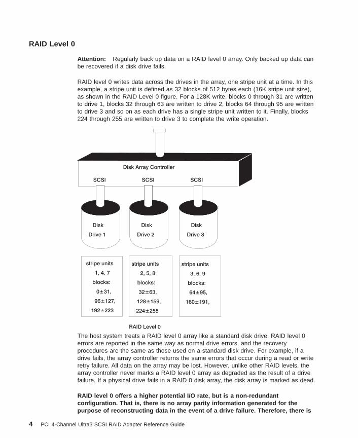
RAID level 0 writes data across the drives in the array, one stripe unit at a time. In thisexample, a stripe unit is defined as 32 blocks of 512 bytes each (16K stripe unit size),as shown in the RAID Level 0 figure. For a 128K write, blocks 0 through 31 are writtento drive 1, blocks 32 through 63 are written to drive 2, blocks 64 through 95 are writtento drive 3 and so on as each drive has a single stripe unit written to it. Finally, blocks224 through 255 are written to drive 3 to complete the write operation.
Disk Array Controller
SCSI SCSI SCSI
Disk
Drive 1
Disk
Drive 2
Disk
Drive 3
RAID Level 0
stripe units
2, 5, 8
blocks:
32±63,
128±159,
224±255
stripe units
1, 4, 7
blocks:
0±31,
96±127,
192±223
stripe units
3, 6, 9
blocks:
64±95,
160±191,
The host system treats a RAID level 0 array like a standard disk drive. RAID level 0errors are reported in the same way as normal drive errors, and the recoveryprocedures are the same as those used on a standard disk drive. For example, if adrive fails, the array controller returns the same errors that occur during a read or writeretry failure. All data on the array may be lost. However, unlike other RAID levels, thearray controller never marks a RAID level 0 array as degraded as the result of a drivefailure. If a physical drive fails in a RAID 0 disk array, the disk array is marked as dead.
RAID level 0 offers a higher potential I/O rate, but is a non-redundantconfiguration. That is, there is no array parity information generated for thepurpose of reconstructing data in the event of a drive failure. Therefore, there is
4 PCI 4-Channel Ultra3 SCSI RAID Adapter Reference Guide

no error recovery beyond what is normally provided on a single drive. All data inthe array must be backed up regularly to protect against data loss.
RAID Level 1
Attention: Although a RAID level 1 array has data redundancy, you should regularlyback up data on the array. This is the only way to recover data in an event such asaccidental file deletion or disaster recovery. You can continue to operate the array indegraded mode until you replace the drive. However, you should replace the drive assoon as possible. If you cannot replace the drive immediately, back up your data, file byfile, to prevent potential data loss.
RAID level 1 transparently mirrors data by duplicating data stripes across drives. Whendata is written to a drive, it is also written to a mirrored stripe.
RAID level 1 has traditionally been used for critical fault-tolerant transaction processing.Mirrored data provides high reliability. When a small block size is used, mirrored dataalso provides a high I/O rate. However, RAID level 1 is a more costly RAID solutionbecause it requires a mirrored data stripe for every physical drive in the array.
RAID level 1 writes data across the drives in the array, one stripe unit at a time. In thisexample, a stripe unit is defined as 64 blocks of 512 bytes each (32K stripe unit size)as shown in the RAID Level 1 figure. For a 32K write, blocks 0 through 63 are written todrive 1 and the mirrored data blocks 0-63 are written to the mirrored data drive .
Disk Array Controller
SCSI SCSI SCSI
Disk
Drive 1
data
SPARE
mirrored
stripe unit
1
blocks
0±63
stripe unit
1
blocks
0±63
RAID Level 1
Disk
Drive 2
mirror
Chapter 1. Adapter Overview 5

If a single drive fails in a RAID level 1 array, you can continue to use the array. A RAIDlevel 1 array operating with a single failed drive is said to be operating in degradedmode. Whenever you read or write to a disk array in degraded mode, the arraycontroller retrieves the failed drive’s data from its mirrored drive. Although you cancontinue to operate the RAID level 1 array with a failed drive, you should replace thedrive and restore the array as soon as possible.
Using the Perform Consistency Check menu allows the array controller to compare thedata drive and mirror to verify consistency after an abnormal system shutdown. See“Performing a Consistency Check on a Disk Array” on page 37 for more information.
Raid Level 5
Attention: Although a RAID level 5 array maintains parity information, you shouldregularly back up data on the array. This is the only way to recover data in an eventsuch as accidental file deletion or disaster recovery. You can continue to operate thearray in degraded mode until you replace the drive. However, you should replace thedrive as soon as possible. If you cannot replace the drive immediately, back up yourdata, file by file, to prevent potential data loss.
RAID level 5 stripes data across all drives in the array, one stripe unit at a time (a stripeunit can contain multiple blocks). RAID level 5 also writes array parity data. The paritydata is spread across all the drives.
6 PCI 4-Channel Ultra3 SCSI RAID Adapter Reference Guide

In the RAID Level 5 example figure, a stripe unit is defined as 64 blocks of 512 byteseach (32K stripe unit size).
Disk Array Controller
SCSI SCSI SCSI SCSI
Disk
Drive 1
Disk
Drive 2
Disk Hot Spare
Drive 3 Drive
Parity
Parity
Parity
stripe unit
1
stripe unit
2
stripe unit
3
stripe unit
4
stripe unit
5
RAID Level 5
stripe unit
6
Stripes are written as follows:
v Stripe 1 is written in the first position to drive 2
v Stripe 2 is written to drive 3
v Parity data for the data in stripes 1 and 2 are written to drive 1
If a drive fails in a RAID level 5 array, you can continue to use the array normally. ARAID level 5 array operating with a single failed drive is said to be operating indegraded mode. Whenever data is read from a degraded disk array, the array controllerrecalculates the data on the failed drive by using data and parity blocks on theoperational drives.
Chapter 1. Adapter Overview 7

For example, to recalculate data in data stripe unit 2 in the RAID level 5 figure (the firstposition on drive 3), the array controller would use the parity information from drive 1and the data from drive 2 (data stripe unit 1) to reconstruct the data. This process isrepeated to reconstruct each block of the failed drive, as needed, so you can continueto operate the RAID level 5 array.
The Perform Consistency Check menu allows the array controller to check the integrityof the array parity. If the array subsystem has an abnormal system shutdown, you maycheck and repair array parity/mirror on the affected disk array(s). See “Performing aConsistency Check on a Disk Array” on page 37 for more information.
Raid Level 5 Enhanced (5E)
Attention: Although a RAID level 5E array maintains parity information, you shouldregularly back up data on the array. This is the only way to recover data in an eventsuch as accidental file deletion or disaster recovery. You can continue to operate thearray in degraded mode until you replace the drive. However, you should replace thedrive as soon as possible. If you cannot replace the drive immediately, back up yourdata, file by file, to prevent potential data loss.
Note: RAID level 5E requires a minimum of four drives.
RAID level 5E is an IBM enhancement of RAID level 5. Traditional RAID 5 has activedrives plus an inactive hot spare drive. In RAID 5E however, the hot spare drive isincorporated as an active element in the array. The data is laid out in such a way thatthe Hot spare capacity is spread among all the drives in the array. If a drive failureoccurs, the data on the failed drive is reconstructed using the Hot spare capacity on theremaining drives in the array. This process of reconstruction in a RAID 5E array isreferred to as compression. When compression is complete the disk array will have anOptimal status. A compressed RAID 5E array is identical to an optimal traditional RAID5 array. If the failed drive in a RAID 5E array is then replaced with a new Hot sparedrive, the array data on the array will migrate back to a RAID 5E layout with Hot sparecapacity again spread among all the drives. See “Assigning Hot Spare Drives” onpage 36. This process is referred to as decompression. Decompression will begin whena Hot spare, of equal or greater capacity to the failed drive is added.
8 PCI 4-Channel Ultra3 SCSI RAID Adapter Reference Guide

Disk Array Controller
SCSI SCSI SCSI SCSI
Data Data Data Data
SpareSpace
SpareSpace
SpareSpace
SpareSpace
Combined Spare Spaceequals
Total Hot Spare Capacity
Parity
Parity
Parity
Parity
stripe unit
1
stripe unit stripe unit
stripe unit
2
65
stripe unit
3
stripe unit
stripe unit
4
9
121110
stripe unit
stripe unit
7
RAID Level 5E
stripe unit
stripe unit stripe unit
8
Note: If a Hot spare is added while the disk array has a status of Compressing, thenthe disk array will finish compressing before decompressing the disk array.
On a decompressed RAID level 5E array data stripes have a 3:1 ratio to data parity.
Stripes are written as follows:
v Stripe 1 is written in first position of drive 2
v Stripe 2 is written to drive 3
v Stripe 3 is written to drive 4
v After all three stripes are written the data parity is written to drive 1.
The data parity is calculated using stripes 1,2 and 3.
Chapter 1. Adapter Overview 9
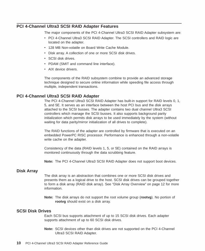
PCI 4-Channel Ultra3 SCSI RAID Adapter FeaturesThe major components of the PCI 4-Channel Ultra3 SCSI RAID Adapter subsystem are:
v PCI 4-Channel Ultra3 SCSI RAID Adapter. The SCSI controllers and RAID logic arelocated on the adapter.
v 128 MB Non-volatile on Board Write Cache Module.
v Disk array. A collection of one or more SCSI disk drives.
v SCSI disk drives.
v PDAM (SMIT and command line interface).
v AIX device drivers.
The components of the RAID subsystem combine to provide an advanced storagetechnique designed to secure online information while speeding file access throughmultiple, independent transactions.
PCI 4-Channel Ultra3 SCSI RAID AdapterThe PCI 4-Channel Ultra3 SCSI RAID Adapter has built-in support for RAID levels 0, 1,5, and 5E. It serves as an interface between the host PCI bus and the disk arraysattached to the SCSI busses. The adapter contains two dual channel Ultra3 SCSIcontrollers which manage the SCSI busses. It also supports background parityinitialization which permits disk arrays to be used immediately by the system (withoutwaiting for data parity/mirror initialization of all drives to complete).
The RAID functions of the adapter are controlled by firmware that is executed on anembedded PowerPC RISC processor. Performance is enhanced through a non-volatilewrite cache on the adapter.
Consistency of the data (RAID levels 1, 5, or 5E) contained on the RAID arrays ismonitored continuously through the data scrubbing feature.
Note: The PCI 4-Channel Ultra3 SCSI RAID Adapter does not support boot devices.
Disk ArrayThe disk array is an abstraction that combines one or more SCSI disk drives andpresents them as a logical drive to the host. SCSI disk drives can be grouped togetherto form a disk array (RAID disk array). See “Disk Array Overview” on page 12 for moreinformation.
Note: The disk arrays do not support the root volume group (rootvg ). No portion ofrootvg should exist on a disk array.
SCSI Disk DrivesEach SCSI bus supports attachment of up to 15 SCSI disk drives. Each adaptersupports attachment of up to 60 SCSI disk drives.
Note: SCSI devices other than disk drives are not supported on the PCI 4-ChannelUltra3 SCSI RAID Adapter.
10 PCI 4-Channel Ultra3 SCSI RAID Adapter Reference Guide

128 MB Non-volatile on Board Write CacheThe PCI 4-Channel Ultra3 SCSI RAID Adapter has battery backed non-volatile on boardwrite cache. Select Display Status of Adapter Write Cache in the PDAM to display thestatus of the write cache.
PCI SCSI Disk Array Manager (PDAM)The PCI 4-Channel Ultra3 SCSI RAID Adapter is managed by the PDAM. The PDAM isthe only interface to the RAID configuration, monitoring, and recovery features of theadapter. Some of the tasks performed using the PDAM include:
v Check device status for the disk array on your system.
v Create and delete disk arrays.
v Configure and reconfigure disk arrays.
v Change disk array configuration attributes.
v Check and repair array parity/mirror on disk array.
v Display information of physical drives and disk arrays.
v Reconstruct a RAID level 1, 5, or 5E disk array after a single drive failure.
v Delete/recreate a RAID level 0 disk array after a drive failure, or a RAID level 1, 5, or5E disk array after multiple drive failures.
v Use adapter configuration and error recovery options.
The PDAM is supported through the SMIT interface. See “Chapter 2. Installing the PCI4-Channel Ultra3 SCSI RAID Adapter Software” on page 21 for more information
Chapter 1. Adapter Overview 11

Disk Array OverviewThe disk array is an abstraction that combines one or more SCSI disk drives andpresents them as an logical drive to the host.
The following figure illustrates a typical configuration of a RAID disk array connected toa host system through a PCI 4-Channel Ultra3 SCSI RAID Adapter. This disk array ismade up of three physical disks located on three separate SCSI buses. Thisconfiguration results in making the disk array available as hdisk1. The figure includesthe logical names assigned by the system during configuration.
SCSI AdapterDevice Driver
(scraid_dd)
Array Controller
Host
SCSI Device
Driver(scdisk)
SCSI
Busses
hdisk1
scraid0
SCSI Adapter
PCI 4-Channel Ultra3 SCSI RAID Adapter
Disk Array ParametersDisk arrays are configured using the PDAM. See “Chapter 2. Installing the PCI4-Channel Ultra3 SCSI RAID Adapter Software” on page 21 for additional information.
Each disk array has a set of parameters that determine how data is stored andaccessed on it. Some of these parameters may differ for each array, while otherparameters must be the same for all arrays created on the adapter. All disk arraysattached to a PCI 4-Channel Ultra3 SCSI RAID Adapter must share the same stripe unit
12 PCI 4-Channel Ultra3 SCSI RAID Adapter Reference Guide
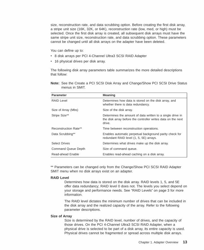
size, reconstruction rate, and data scrubbing option. Before creating the first disk array,a stripe unit size (16K, 32K, or 64K), reconstruction rate (low, med, or high) must beselected. Once the first disk array is created, all subsequent disk arrays must have thesame stripe unit size, reconstruction rate, and data scrubbing option. These parameterscannot be changed until all disk arrays on the adapter have been deleted.
You can define up to:
v 8 disk arrays per PCI 4-Channel Ultra3 SCSI RAID Adapter
v 16 physical drives per disk array.
The following disk array parameters table summarizes the more detailed descriptionsthat follow:
Note: See the Create a PCI SCSI Disk Array and Change/Show PCI SCSI Drive Statusmenus in SMIT.
Parameter Meaning
RAID Level Determines how data is stored on the disk array, andwhether there is data redundancy.
Size of Array (Mbs) Size of the disk array.
Stripe Size** Determines the amount of data written to a single drive inthe disk array before the controller writes data on the nextdrive.
Reconstruction Rate** Time between reconstruction operations.
Data Scrubbing** Enables automatic perpetual background parity check forredundant RAID level (1, 5, 5E) arrays.
Select Drives Determines what drives make up the disk array.
Command Queue Depth Size of command queue.
Read-ahead Enable Enables read-ahead caching on a disk array.
** Parameters can be changed only from the Change/Show PCI SCSI RAID AdapterSMIT menu when no disk arrays exist on an adapter.
RAID LevelDetermines how data is stored on the disk array. RAID levels 1, 5, and 5Eoffer data redundancy; RAID level 0 does not. The levels you select depend onyour storage and performance needs. See “RAID Levels” on page 3 for moreinformation.
The RAID level dictates the minimum number of drives that can be included inthe disk array and the realized capacity of the array. Refer to the followingparameter descriptions.
Size of ArraySize is determined by the RAID level, number of drives, and the capacity ofthose drives. On the PCI 4-Channel Ultra3 SCSI RAID Adapter, when aphysical drive is selected to be part of a disk array, its entire capacity is used.Physical drives cannot be fragmented or spread across multiple disk arrays.
Chapter 1. Adapter Overview 13

Note: The capacity should be the same for each drive in the disk array. Ifdrives differ in capacity, the array controller uses the smallest capacityin the selected drive list to determine the usable capacity of all thedrives when creating the disk array.
To determine the size of a disk array you want to create on your arraysubsystem, you need to know the capacity of a single drive. To determine thisvalue, select the Change/Show PCI SCSI Drive Status option from the PCISCSI Disk Array Manager menu in SMIT.
Each time you create a new disk array from spare drives, use the followingformulas to determine the maximum size of the disk array you can create. Thiscalculation depends on both the RAID level of the disk array you want tocreate and the size of the drives:
RAID level 0Multiply the number of drives by the drive capacity.
RAID level 1Multiply the number of drives by the drive capacity and divide by 2.
RAID level 5Multiply one less than the number of drives by the drive capacity.
RAID level 5EMultiply two less than the number of drives by the drive capacity.
The resulting capacity for each of the preceding calculations yields theapproximate size of the disk array.
Stripe SizeSpecifies the amount of data written on a single drive in the disk array beforethe controller continues writing the data on the next drive in the disk array. Forexample, if the stripe unit size of a RAID level 0 disk array is 16384 bytes(16K), the controller will write 16384 bytes of data on drive 1, the next 16384bytes of data on drive 2, the next on drive 3, and so on.
The adapter supports stripe sizes of 16K (16384), 32K (32768) and 64K(65536).
Note: The stripe size parameter can only be changed if there are no diskarrays associated with the adapter.
Reconstruction RateControls the rate of data reconstruction on RAID level 1, 5, and 5E disk arrays(data on a RAID level 0 array cannot be reconstructed). This parametercontrols the amount of resources the adapter allocates for the reconstruction.This is a PCI 4-Channel Ultra3 SCSI RAID Adapter attribute and can only bemodified before the first disk array is created. Low, medium and high rates aresupported.
Note: The reconstruction rate parameter can only be changed if there are nodisk arrays associated with the adapter.
14 PCI 4-Channel Ultra3 SCSI RAID Adapter Reference Guide
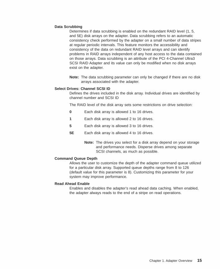
Data ScrubbingDetermines if data scrubbing is enabled on the redundant RAID level (1, 5,and 5E) disk arrays on the adapter. Data scrubbing refers to an automaticconsistency check performed by the adapter on a small number of data stripesat regular periodic intervals. This feature monitors the accessibility andconsistency of the data on redundant RAID level arrays and can identifyproblems in RAID arrays independent of any host access to the data containedon those arrays. Data scrubbing is an attribute of the PCI 4-Channel Ultra3SCSI RAID Adapter and its value can only be modified when no disk arraysexist on the adapter.
Note: The data scrubbing parameter can only be changed if there are no diskarrays associated with the adapter.
Select Drives: Channel SCSI IDDefines the drives included in the disk array. Individual drives are identified bychannel number and SCSI ID
The RAID level of the disk array sets some restrictions on drive selection:
0 Each disk array is allowed 1 to 16 drives.
1 Each disk array is allowed 2 to 16 drives.
5 Each disk array is allowed 3 to 16 drives.
5E Each disk array is allowed 4 to 16 drives.
Note: The drives you select for a disk array depend on your storageand performance needs. Disperse drives among separateSCSI channels, as much as possible.
Command Queue DepthAllows the user to customize the depth of the adapter command queue utilizedfor a particular disk array. Supported queue depths range from 8 to 126(default value for this parameter is 8). Customizing this parameter for yoursystem may improve performance.
Read Ahead EnableEnables and disables the adapter’s read ahead data caching. When enabled,the adapter always reads to the end of a stripe on read operations.
Chapter 1. Adapter Overview 15
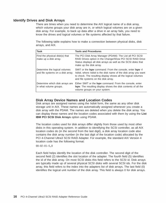
Identify Drives and Disk ArraysThere are times when you need to determine the AIX logical name of a disk array,which volume groups your disk array are in, or which logical volumes are on a givendisk array. For example, to back up data after a drive in an array fails, you need toknow the drives and logical volumes or file systems affected by that failure.
The following table explains how to make a connection between physical disks, diskarrays, and AIX.
Task Tools and Procedures
Find the physical disk(s) thatmake up a disk array.
The PCI Disk Array Manager (PDAM): The List all PCI SCSIRAID Drives option in the Change/Show PCI SCSI RAID DriveStatus displays all disk arrays as well as the SCSI disks thatmake up the disk array.
Determine the logical volumesand file systems on a disk array.
SMIT or the lspv command: From the console, enter lspv -lhdisk, where hdisk is the disk name of the disk array you wantto check. The resulting display shows all the logical volumesand file systems on the disk array.
Determine which disk arrays arein what volume groups.
Either SMIT or the lspv command: From the console, enterlspv . The resulting display shows the disk contents of all thevolume groups on your system.
Disk Array Device Names and Location CodesDisk arrays are assigned names using the hdisk form, the same as any other diskstorage unit in AIX. These names are automatically assigned whenever you create adisk array with the PDAM. The names are deleted when you delete the disk array. Youcan display these names and the location codes associated with them by using the ListIBM PCI SCSI Disk Arrays option using PDAM.
The location codes used for disk arrays differ slightly from those used by most otherdisks in this operating system. In addition to identifying the SCSI controller, as all AIXlocation codes do (in the second from the last digit), a disk array location code alsocontains the disk array number (in the last digit of the location code) allocated by thePCI 4-Channel Ultra3 SCSI RAID Adapter. For example, the standard AIX Version 4location code has the following format:
00-02-01-5,0
Each field helps identify the location of the disk controller. The second digit of thesecond field (2) identifies the slot location of the adapter. The fourth field (5) identifiesthe id of the disk array. On most SCSI disks this field refers to the SCSI id. Disk arraysare typically made up of several physical SCSI disks with several SCSI ids. For the diskarray, this field refers to the index into the adapters list of disk arrays. The last field (0)identifies the logical unit number of the disk array. This field is always 0 for disk arrays.
16 PCI 4-Channel Ultra3 SCSI RAID Adapter Reference Guide

For example, you may see a display similar to the following when you select the ListIBM PCI SCSI Disk Arrays option using PDAM.
In the following sample display, there are four disk arrays (disk array 00 through 03)attached to one PCI 4-Channel Ultra3 SCSI RAID Adapter (slot 1).
hdisk1 Available Raid 5 04-01-00-0,0 2064 MB Status OPTIMALhdisk1 11 Channel 1 ID 1 ONLINEhdisk1 22 Channel 2 ID 2 ONLINEhdisk1 33 Channel 3 ID 3 ONLINE
hdisk2 Available Raid 1 04-01-00-1,0 2048 MB Status OPTIMALhdisk2 12 Channel 1 ID 2 ONLINEhdisk2 20 Channel 2 ID 0 ONLINE
hdisk3 Available Raid 0 04-01-00-2,0 3072 MB Status OPTIMALhdisk3 13 Channel 1 ID 3 ONLINEhdisk3 21 Channel 2 ID 1 ONLINEhdisk3 30 Channel 3 ID 0 ONLINE
hdisk4 Defined Raid 0 04-01-00-3,0 2144 MB Status DEADhdisk4 10 Channel 1 ID 0 FAILED DRIVE
Disk Array ODM InformationThe operating system stores information about each device that can be connected to itin a database maintained by the Object Data Manager (ODM). The information storedabout each device includes the following:
v Device class, subclass, and type
v Device parent
v Device location code
v Connection point
v Attributes.
The following sections describe the values stored for each of these categories for thePCI 4-Channel Ultra3 SCSI RAID Adapter.
Device Class, Subclass, and TypeA device’s class, subclass, and type unambiguously identify it to the operating system.With this information, the operating system can locate the device’s record in the ObjectData Manager (ODM) and obtain other information stored in the database about thedevice.
Together, a device’s class, subclass, and type make up the unique type. The PCI4-Channel Ultra3 SCSI RAID Adapter unique type is adapter/pci/14102e00 .
Device ClassDescribes the general category of devices for a device. For example, allprinters are in the printer class. The PCI 4-Channel Ultra3 SCSI RAID Adapteris in the adapter class device class.
Chapter 1. Adapter Overview 17

Device SubclassDescribes how the device is connected to the host. This is usually the type ofadapter used to communicate between the host and the device. For example,standard SCSI disks are in the scsi subclass. The PCI 4-Channel Ultra3 SCSIRAID Adapter is in the pci subclass because it uses a PCI bus to communicateto the host.
Device TypeDescribes the characteristics of a device within a class. For example, for astandard SCSI disk, the type can be a description of its storage capacity, suchas 2gb. To uniquely identify the PCI 4-Channel Ultra3 SCSI RAID Adapterwithin its class, the PCI configuration signature (device id/vendor id) is used.The PCI 4-Channel Ultra3 SCSI RAID Adapter signature is 0x14102e00.
Device ParentA device parent is the device that must be configured or defined before the device itselfcan be configured or defined. A device can have only one parent. For example, theparent device of a standard SCSI disk is the SCSI adapter, because the system cannotcommunicate with the disk drive without going through the adapter. The parent device isspecified by a system assigned name, such as scsi0, scsi1, or vscsi. The PCI busattached to the adapter is the device parent of the PCI 4-Channel Ultra3 SCSI RAIDAdapter . This is normally bus0 or bus1.
Device Location CodeOn AIX systems, all devices have device location codes that uniquely identify them tothe system. The PCI 4-Channel Ultra3 SCSI RAID Adapter location code conforms toexisting PCI adapters on the AIX platform. The location code is of the form: 04-0Nwhere N is the slot number. Disk arrays attached to the PCI 4-Channel Ultra3 SCSIRAID Adapter follow the location code convention of existing SCSI disks and are of theform: 04-0N-00-00. The last “nibble” indicates the device ID and LUN . For a PCI4-Channel Ultra3 SCSI RAID Adapter attached disk array, the LUN field will always bezero and the ID field will be the index into the adapter’s list of disk arrays. Theselocation codes follow AIX convention for adapters and devices. See AIX Version 4System Management Guide: Operating System and Devices for a thorough descriptionof all of the location code fields.
PCI 4-Channel Ultra3 SCSI RAID Adapter AIX ConfigurationAs with any device connected to an AIX system, the PCI 4-Channel Ultra3 SCSI RAIDAdapter must be defined and configured before it can be accessed.
v A device is defined when the system creates a record for it in the CustomizedDatabase portion of the Object Data Manager (ODM). The ODM database containsinformation about all the devices that can be connected to the system. In the ODMdatabase, device information is stored in an object relationship. The ODM databasestores generic descriptions of the various supported devices in its Predefineddatabase. For each instance of a particular device type, the system creates aseparate copy of the predefined record.
v A device is configured when all necessary device drivers are loaded into the kerneland all other components necessary for communication with the device areconfigured. When configuration is completed, the device is marked as available.
18 PCI 4-Channel Ultra3 SCSI RAID Adapter Reference Guide

At boot time, or whenever you invoke the cfgmgr command, the AIX operating systemconfigures the PCI 4-Channel Ultra3 SCSI RAID Adapter and any previously createddisk arrays automatically.
Chapter 1. Adapter Overview 19

20 PCI 4-Channel Ultra3 SCSI RAID Adapter Reference Guide
Chapter 2. Installing the PCI 4-Channel Ultra3 SCSI RAID AdapterSoftware
In order to correctly install the PCI 4-Channel Ultra3 SCSI RAID Adapter software,complete the following steps carefully. Failure to follow these steps may result in errorsthat will not allow further configuration of the PCI 4-Channel Ultra3 SCSI RAID Adapter.
This chapter contains information about:
v Installing the PCI 4-Channel Ultra3 SCSI RAID Adapter Software
v Installing a PCI 4-Channel Ultra3 SCSI RAID Adapter Software Update
v Verifying the PCI 4-Channel Ultra3 SCSI RAID Adapter Software Installation.
Installing an PCI 4-Channel Ultra3 SCSI RAID Adapter on AIX Version 4This section describes the steps for installing the PCI 4-Channel Ultra3 SCSI RAIDAdapter software for the first time on AIX Version 4. Note that it is often not necessaryto install the PCI 4-Channel Ultra3 SCSI RAID Adapter software as a separate step. Ifthe PCI 4-Channel Ultra3 SCSI RAID Adapter was installed in the system when therequired level of AIX version 4 was installed, then all the necessary software for theadapter was installed.
Note: AIX Version 4.3.3 or later is necessary for PCI 4-Channel Ultra3 SCSI RAIDAdapter
1. The PCI RAID Adapter requires AIX Version 4.3.3 or later.
2. Do not run the diagnostics on the PCI 4-Channel Ultra3 SCSI RAIDAdapter at anystage during the installation of the PCI 4-Channel Ultra3 SCSI RAID Adaptersoftware. Wait until installation is complete before running diagnostics. In mostcases, it is unnecessary to run diagnostics following installation. See the section onPCI 4-Channel Ultra3 SCSI RAID Adapter Service Aids to determine if diagnosticsare required.
3. Array controller microcode is distributed on the PCI 4-Channel Ultra3 SCSI RAID.Array controller microcode updates can be downloaded at:http://www.rs6000.ibm.com/support/micro/download.html
Note: Downloading of array controller microcode is not usually required because thosefiles are already installed on the adapter. Read and follow any instructionsshipped with the PCI 4-Channel Ultra3 SCSI RAID Adapter for situations inwhich download is required.
21

PrerequisiteEnsure that the PCI 4-Channel Ultra3 SCSI RAID Adapter software is not alreadyinstalled by using the command:
lslpp - l devices.pci.14102e00.rte
If the software is not installed, the following messages is displayed:
lslpp: 0504-132 Fileset devices.pci.14102e00.rte not installed
Procedure1. Insert the install media into the machine.
At this point the software can be installed using SMIT or on the command line usingthe cfgmgr command.
To install the software using the cfgmgr command, the PCI 4-Channel Ultra3 SCSIRAID Adapter must be in the machine.
2. To install the software from the command line, type cfgmgr -i devicename
Note: devicename can be a directory or a device (ie. /dev/rmt0).
To install the software using SMIT, follow steps 3 through 7.
3. Run the smit command and select:
a. Software Installation and Maintenance
b. Install and Update Software
c. Install and Update Software by Package Name
4. Select Input Device using F4.
Select Devices to Install using F4 to display the list of install images on the tape orCD-ROM.
Then select devices.pci.14102e00 ALL . Press Enter to begin the installationprocess.
During the installation process, the screen will display messages while the PCI4-Channel Ultra3 SCSI RAID Adapter software is loaded onto the system. If themessages indicate that the installation was not successful, repeat the installationprocedure or contact your service representative.
22 PCI 4-Channel Ultra3 SCSI RAID Adapter Reference Guide

5. The screen will look similar to the following:
Install and Update Software by Package Name (includes devices and printers)
Type or select values in entry fields.Press Enter AFTER making all desired changes.
[Entry Fields]
* INPUT device / directory for software .* SOFTWARE to install [devices.pci.14102e00 ]PREVIEW only? (install operation will NOT occur) noCOMMIT software updates? yesSAVE replaced files? noAUTOMATICALLY install requisite software? yesEXTEND file systems if space needed? yesOVERWRITE same or newer versions? noVERIFY install and check file sizes? noInclude corresponding LANGUAGE filesets yesDETAILED output? noProcess multiple volumes? Yes
F1=Help F2=Refresh F3=Cancel F4=ListF5=Reset F6=Cmand F7=Edit F8=ImageF9=Shell F10=Exit Enter=Do
6. To make the PCI 4-Channel Ultra3 SCSI RAID Adapter available, type cfgmgr atthe command line and press Enter. Alternatively, you may shutdown the system andrestart it.
7. Verify the PCI 4-Channel Ultra3 SCSI RAID Adapter software and controllerconnections (see “Verifying the PCI 4-Channel Ultra3 SCSI RAID Adapter SoftwareInstallation” on page 25.
8. Ensure that all PCI 4-Channel Ultra3 SCSI RAID Adapters are in the available state.
Note: If the instructions shipped with the PCI 4-Channel Ultra3 SCSI RAID Adapterrequire downloading of microcode, those actions will begin at this point.
The installation of the PCI 4-Channel Ultra3 SCSI RAID Adapter hardware and softwareis now complete.
Chapter 2. Installing the PCI 4-Channel Ultra3 SCSI RAID Adapter Software 23

Installing a PCI 4-Channel Ultra3 SCSI RAID Adapter Software UpdateThis checklist describes the steps required to update the PCI 4-Channel Ultra3 SCSIRAID Adapter software on a host system that is already running the PCI 4-ChannelUltra3 SCSI RAID Adapter software.
Procedure1. Insert the new PCI 4-Channel Ultra3 SCSI RAID Adapter software media into the
media device.
2. From SMIT, select:
a. Software Installation and Maintenance
b. Install and Update Software
c. Install Software by Fix (APAR)
3. Select Input Device using F4.
4. Select Apar number that you would like to install. Toggle COMMIT software to noand SAVE replaced files to yes
5. Press Enter to begin the installation process.
The screen will look similar to the following:
Update Software by Fix
Type or select values in entry fields.Press Enter AFTER making all desired changes.
[Entry Fields]
* INPUT device / directory for software .* FIXES to install [IY05058]PREVIEW only? (install operation will NOT occur) noCOMMIT software updates? yesSAVE replaced files? noEXTEND file systems if space needed? yesVERIFY install and check file sizes? noDETAILED output? noProcess multiple volumes yes
F1=Help F2=Refresh F3=Cancel F4=ListF5=Reset F6=Cmand F7=Edit F8=ImageF9=Shell F10=Exit Enter=Do
6. Press Enter to begin the installation process.
During the installation process, the screen will display messages while the PCI4-Channel Ultra3 SCSI RAID Adapter software is loaded onto the system. If themessages indicate that the installation was not successful, repeat the installationprocedure or contact your service representative
7. Type the cfgmgr command to make the PCI 4-Channel Ultra3 SCSI RAID Adapteravailable and press Enter. Alternatively, you may shutdown and restart the system.
8. Verify the PCI 4-Channel Ultra3 SCSI RAID Adapter software and controllerconnections.
24 PCI 4-Channel Ultra3 SCSI RAID Adapter Reference Guide

Verifying the PCI 4-Channel Ultra3 SCSI RAID Adapter Software Installation1. For AIX Version 4.3.3 or later, verify the PCI 4-Channel Ultra3 SCSI RAID Adapter
software installation by entering the following command:
lslpp -l devices.pci.14102e00.rte
The displayed text should indicate that the PCI 4-Channel Ultra3 SCSI RAIDAdapter Software is in the Committed state.
2. After you have verified the installation, go to “Chapter 3. Managing the PCI4-Channel Ultra3 SCSI RAID Adapter” on page 27.
Chapter 2. Installing the PCI 4-Channel Ultra3 SCSI RAID Adapter Software 25

26 PCI 4-Channel Ultra3 SCSI RAID Adapter Reference Guide
Chapter 3. Managing the PCI 4-Channel Ultra3 SCSI RAID Adapter
You can manage the PCI 4-Channel Ultra3 SCSI RAID Adapter by using the PCI SCSIDisk Array Manager (PDAM), System Management Interface Tool (SMIT), or for sometasks, the AIX command line. In most instances, disk arrays are managed by usingSMIT.
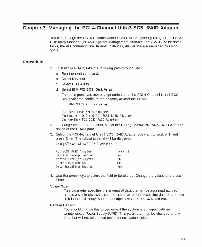
Procedure1. To start the PDAM, take the following path through SMIT:
a. Run the smit command.
b. Select Devices
c. Select Disk Array
d. Select IBM PCI SCSI Disk Array
From this panel you can change attributes of the PCI 4-Channel Ultra3 SCSIRAID Adapter, configure the adapter, or start the PDAM:
IBM PCI SCSI Disk Array
PCI SCSI Disk Array ManagerConfigure a Defined PCI SCSI RAID AdapterChange/Show PCI SCSI RAID Adapter
2. To change adapter parameters, select the Change/Show PCI SCSI RAID Adapteroption of the PDAM panel.
3. Select the PCI 4-Channel Ultra3 SCSI RAID Adapter you want to work with andpress Enter. The following panel will be displayed:
Change/Show PCI SCSI RAID Adapter
PCI SCSI RAID Adapter scraid1Battery Backup Enabled noStripe Size (in KBytes) 16Reconstruction Rate medData Scrubbing Enabled yes
4. Use the arrow keys to select the field to be altered. Change the values and pressEnter.
Stripe SizeThis parameter specifies the amount of data that will be accessed (striped)across a single physical disk in a disk array before accessing data on the nextdisk in the disk array. Supported stripe sizes are 16K, 32K and 64K.
Battery BackupYou should change this to yes only if the system is equipped with anUninterrupted Power Supply (UPS). This parameter may be changed at anytime, but will not take effect until the next system reboot.
27

Reconstruction RateThis parameter specifies the rate at which a drive reconstruction (data rebuild)will occur. If the rate is set to low, the reconstruction will be performed at aslower rate but overall system performance should not be impacted duringreconstructs. The opposite is true if the rate is set to high.
Data ScrubbingThis parameter specifies whether data scrubbing will be enabled on redundantlevel disk arrays created on this adapter. A value of yes indicates that a regularperiodic interval, a consistency check will be performed by the adapter on asmall number of data stripes.
Note: The Stripe Size, Reconstruction Rate, and Data Scrubbing parameters may onlybe changed if no disk arrays are currently configured on this PCI 4-ChannelUltra3 SCSI RAID Adapter.
Starting the PCI SCSI Disk Array Manager1. To start the PDAM, take the following SMIT fast path:
smit pdam
2. From the PDAM panel, select the PCI SCSI Disk Array Manager option. The screenthen displays the PCI SCSI Disk Array Manager panel.
PCI SCSI Disk Array Manager
List PCI SCSI Disk ArraysCreate a PCI SCSI Disk ArrayDelete a PCI SCSI Disk ArrayConfigure a Defined PCI SCSI Disk ArrayChange/Show a PCI SCSI Disk ArrayReconstruct a PCI SCSI Disk ArrayRevive a FAILED Drive in a PCI SCSI Disk ArrayFail a Drive in a PCI SCSI Disk ArrayChange/Show PCI SCSI RAID Drive StatusPerform Consistency CheckDisplay Status of Adapter Write CacheRecovery Options
28 PCI 4-Channel Ultra3 SCSI RAID Adapter Reference Guide

Creating a Disk ArrayUse the following procedure to create or recreate a disk array:
1. Select the Create a PCI SCSI Disk Array option.
2. When prompted, select a PCI SCSI RAID Adapter .
3. When prompted, select the RAID level .
4. When prompted, select each drive you want in the disk array.
The following considerations apply when assigning drives:
RAID LEVEL
0 Each disk array is allowed 1 to 16 physical SCSI disk drives.
1 Each disk array is allowed 2 to 16 drives.
5 Each disk array is allowed 3 to 16 drives.
5E Each disk array is allowed 4 to 16 drives.
Note: The drives you select for a disk array depend on your storage andperformance needs.
5. After selecting the drives for the disk array, the Create a PCI SCSI Disk Arraypanel containing the disk array parameters is displayed. Use the Down Arrow orEnter key to select the value you want to change, and then enter the new value.
Note: You cannot change the RAID Level parameter or selected drives withoutrestarting the creation procedure.
An example Create a PCI SCSI Disk Array SMIT panel follows
Create a PCI SCSI Disk Array
Entry Fields]PCI SCSI RAID Adapter scraid0RAID Level 0Stripe Size (KBytes) 64Size of Array (MBytes) 1024Select Drives: Channel-SCSI ID 01Command Queue Depth 8Read Ahead Enabled yesInitialize Parity yes
Refer to the following information to determine the values you may use for the diskarray parameters:
RAID LevelThis parameter was selected on a previous panel and cannot be changed.
Stripe SizeThis parameter can be changed but not from this panel. See“Change/Show PCI SCSI Disk Array Parameters” on page 38.
Chapter 3. Managing the Adapter 29

Size of ArrayThis parameter is calculated as the maximum size for the drives and theRAID level specified and may not be changed from this panel.
Command Queue DepthThis parameter can be changed from this panel. This parameter allows youto customize the depth of the adapter command queue for this disk array.
Read Ahead EnabledThis parameter can be changed. See “Change/Show PCI SCSI Disk ArrayParameters” on page 38.
Initialize ParityIf parity is not initialized at disk array creation, data reconstructioncapabilities may be compromised.
Select Drives: Channel-SCSI IDThese are the physical drives that were selected to be part of the diskarray.
Note: The AIX Logical Volume Manager has a limit of 1016 physical partitions perphysical volume. For the default physical partition size of 4 MB, thistranslates to a maximum physical volume size of approximately 4 GB. Largerphysical volumes can be configured by increasing the physical partition size.You will know you have exceeded the 1016 physical partitions per physicalvolume (hdisk) if you receive this message while trying to create a volumegroup on a disk array:
0516-862 mkvg: Unable to create volume group
6. After you have set all the parameters you want to set, press Enter.
After you press Enter, if the Initialize Parity parameter was set to yes, the PCI4-Channel Ultra3 SCSI RAID Adapter automatically initializes the parity/mirror on thenew disk array in the background. The disk array is available for use while theparity/mirror is being initialized. Progress of the parity/mirror initialization can bemonitored by using the List PCI SCSI Disk Arrays option of PDAM.
Note: Parity/mirror initialization is not applicable to RAID level 0 disk arrays.
7. If you need to configure more disk arrays, return to step 1. If you do not need toconfigure more disk arrays, exit PDAM.
8. Create AIX file systems on the disk arrays. See “Adding Disk Arrays to the AIXOperating System” on page 41 for more information.
30 PCI 4-Channel Ultra3 SCSI RAID Adapter Reference Guide

Modifying and Displaying Drive StatusUsing the Change/Show PCI SCSI RAID Drive Status option, you can display the statusof the physical drives and disk arrays, delete a spare drive, add a spare drive, add ahot spare drive, identify a drive, remove a failed drive, or display a physical drive’s VitalProduct Data (VPD).
Change/Show PCI SCSI RAID Drive Status
Move cursor to desired item and press Enter
List all PCI SCSI RAID DrivesDelete a Spare DriveAdd a Spare DriveAdd a Hot Spare DriveIdentify a DriveRemove a FAILED DriveDisplay Vital Product Data
F1=Help F2=Refresh F3=Cancel F8=ImageF9=Shell F10=Exit Enter=Do
There are five possible values that may be displayed for the status of a disk array andseven possible values that may be displayed for the status of a physical drive.
Disk Array StatesThe state of a disk array is uniquely determined by the states of the physical drives thatmake up the disk array. Depending on the number of Failed physical drives,replacement of a Failed drive with a good drive may change the state of the disk arrayfrom Dead to Degraded or Optimal after data rebuild. When a Failed physical drive isreplaced in a Degraded disk array, the data is rebuilt onto the replaced drive before thedisk array state transitions to the Optimal. The figure below depicts the valid disk arraystate transitions.
OptimalAll physical drives in the disk array are Online.
CompressingThis is a special state for RAID level 5E disk arrays only. This state indicatesthat one physical drive in the array is in the Failed state. The data from thefailed drive is compressed onto the Hot-spare by being distributed across thespare space of the remaining drives. When compression is complete the diskarray indicates an Optimal state.
DecompressingThis is a special state for RAID level 5E disk arrays only. Decompressingoccurs on compressed RAID level 5E disk arrays. A RAID level 5E array iscompressed when the disk array is Optimal and there is one physical drive inthe Failed state. When a Hot-spare is added to the disk array, compressed
Chapter 3. Managing the Adapter 31

data on the disk array is decompressed onto the newly added Hot-spare.When decompressing completes the disk array will be Optimal with all physicalarrays in the Online state.
DegradedOne of the physical drives that is part of a redundant disk array is in the Failedstate. For RAID level 5E disk array, one of the physical drives in a compresseddisk array is in the Failed state.
Dead For a non-redundant disk array, this state indicates that one or more physicaldrives are in the Failed state. For a redundant disk array, this state indicatesthat two or more physical drives are in the Failed state. For RAID level 5E diskarrays, this state indicates that three or more physical drives are in the Failedstate. A Dead disk array is not accessible.
Physical Disk StatesOnline The drive is part of a disk array and is functioning properly.
Spare The drive is connected to and spun up by the PCI 4-Channel Ultra3SCSI RAID Adapter but not configured into a disk array. This drive isavailable for the creation of a disk array.
Failed The drive was Failed by the PCI 4-Channel Ultra3 SCSI RAIDAdapter or the user and must be replaced. A drive may go to theFailed state if one of the following conditions occur:
v Drive does not respond to selection.
v Drive failed to spin-up.
v Fail in inquiry or read capacity.
v Fail to read or write reserve area.
v Drive fails to respond to SCSI commands.
v Inquiry, capacity, serial number and SCSI ID do not matchconfiguration data stored on the adapter NVRAM.
v User failed the drive using PDAM.
Reconstruct The drive is undergoing a data reconstruction operation.
Warning The drive has been put into a Warning state as the result ofPreventative Failure Analysis (PFA) error reported by the disk. Theseverity of this status depends on the RAID level of the disk array.
In all cases, the Warning drive should be replaced as soon aspossible.
Hot Spare The drive automatically replaces an equivalent Failed drive in aredundant disk array.
Non Existent A drive is marked as non existent if no device is detected at aparticular channel/SCSI ID location.
When the Change/Show Drive Status option is used to change the status of a drive,the state or status of the drive is changed. The following table describes the variousactions performed and the new status of the drive after the action is complete.
32 PCI 4-Channel Ultra3 SCSI RAID Adapter Reference Guide
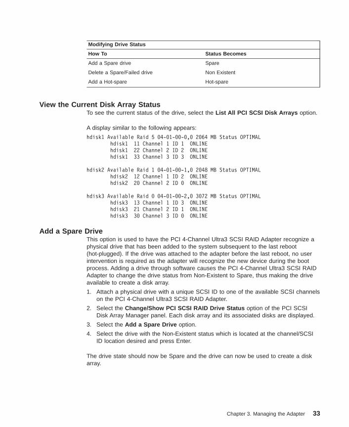
Modifying Drive Status
How To Status Becomes
Add a Spare drive Spare
Delete a Spare/Failed drive Non Existent
Add a Hot-spare Hot-spare
View the Current Disk Array StatusTo see the current status of the drive, select the List All PCI SCSI Disk Arrays option.
A display similar to the following appears:
hdisk1 Available Raid 5 04-01-00-0,0 2064 MB Status OPTIMALhdisk1 11 Channel 1 ID 1 ONLINEhdisk1 22 Channel 2 ID 2 ONLINEhdisk1 33 Channel 3 ID 3 ONLINE
hdisk2 Available Raid 1 04-01-00-1,0 2048 MB Status OPTIMALhdisk2 12 Channel 1 ID 2 ONLINEhdisk2 20 Channel 2 ID 0 ONLINE
hdisk3 Available Raid 0 04-01-00-2,0 3072 MB Status OPTIMALhdisk3 13 Channel 1 ID 3 ONLINEhdisk3 21 Channel 2 ID 1 ONLINEhdisk3 30 Channel 3 ID 0 ONLINE
Add a Spare DriveThis option is used to have the PCI 4-Channel Ultra3 SCSI RAID Adapter recognize aphysical drive that has been added to the system subsequent to the last reboot(hot-plugged). If the drive was attached to the adapter before the last reboot, no userintervention is required as the adapter will recognize the new device during the bootprocess. Adding a drive through software causes the PCI 4-Channel Ultra3 SCSI RAIDAdapter to change the drive status from Non-Existent to Spare, thus making the driveavailable to create a disk array.
1. Attach a physical drive with a unique SCSI ID to one of the available SCSI channelson the PCI 4-Channel Ultra3 SCSI RAID Adapter.
2. Select the Change/Show PCI SCSI RAID Drive Status option of the PCI SCSIDisk Array Manager panel. Each disk array and its associated disks are displayed.
3. Select the Add a Spare Drive option.
4. Select the drive with the Non-Existent status which is located at the channel/SCSIID location desired and press Enter.
The drive state should now be Spare and the drive can now be used to create a diskarray.
Chapter 3. Managing the Adapter 33
Delete a Spare or Failed DriveA drive must be deleted if it is to be removed from the PCI 4-Channel Ultra3 SCSIRAID Adapter and not subsequently replaced. Deleting a drive through software causesthe PCI 4-Channel Ultra3 SCSI RAID Adapter to change the drive status from Spare orFailed to Non-Existent. You cannot delete a drive that is part of a disk array. See“Deleting Disk Arrays from the Operating System” on page 43 to delete the disk array.Next, delete the drive and physically remove the drive from the system.
1. Select the Change/Show PCI SCSI RAID Drive Status option of the PCI SCSIDisk Array Manager panel. All disks, Ultra SCSI PCI RAID Adapters, and associateddisks are displayed.
2. Select the Remove a Spare Drive or Remove a Failed Drive option of the PCISCSI Disk Array Manager panel. For the Remove a Spare Drive option, all sparedrives are displayed. For the Remove a Failed Drive option, all Failed drives aredisplayed.
3. Select the drive to be deleted and press Enter.
Fail a DriveAttention: Do not fail a drive in a RAID level 0 disk array unless you want to replacethe drive. RAID level 0 has no redundancy. Once a drive is Failed in a RAID level 0disk array, it is unlikely that the data can be recovered. Do not fail a drive in a RAIDlevel 1, 5, or 5E disk array if the disk array is already degraded. See “Restoring andRecovering Disk Arrays” on page 53 for instructions on which drives to fail and when tofail them.
You can place a drive in the Failed state when you want to replace a drive in Warningstate and restore or reconstruct a disk array. Failing a drive through software causesthe PCI 4-Channel Ultra3 SCSI RAID Adapter to change the drive status from Warningto Failed. Once a drive is Failed, the PCI 4-Channel Ultra3 SCSI RAID Adapter cannotaccess that drive’s data until you reconstruct the drive data.
1. Select the Fail a Drive in a PCI SCSI Disk Array option. Each disk array and itsassociated disks are displayed.
2. Select the drive to be Failed and press enter.
Attention: If you fail a drive, you may lose data redundancy or data.
The status of the selected drive changes from Online/Warning to Failed
Repeat steps 1 and 2 until you have failed all the drives you want to fail.
Attention: Do not fail more than one Online drive in a single disk array. Failing twodrives with this procedure could result in the loss of all data on the disk array.
Note: A drive that has been Failed manually using the Fail a Drive in a PCI SCSI DiskArray option will be called out by Diagnostics as needing replacement. This isnot necessarily true as the drive may have been functioning properly when thedrive was Failed. See “Reviving a Failed Drive” on page 36.
34 PCI 4-Channel Ultra3 SCSI RAID Adapter Reference Guide
Removing a Disk ArrayTo change the RAID level, drive selection, or size of an existing disk array, see “Deletea PCI SCSI Disk Array”.
Delete a PCI SCSI Disk ArrayDelete the disk array first in order to complete any of the following tasks:
v Change the RAID level of a disk array
v Change the drives that make up a disk array
v Change the stripe size of the adapter
If the disk array is part of a volume group, you must first back up all files in the logicalvolumes and file systems on the disk array and remove the disk array from its volumegroup. See “Deleting Disk Arrays from the Operating System” on page 43.
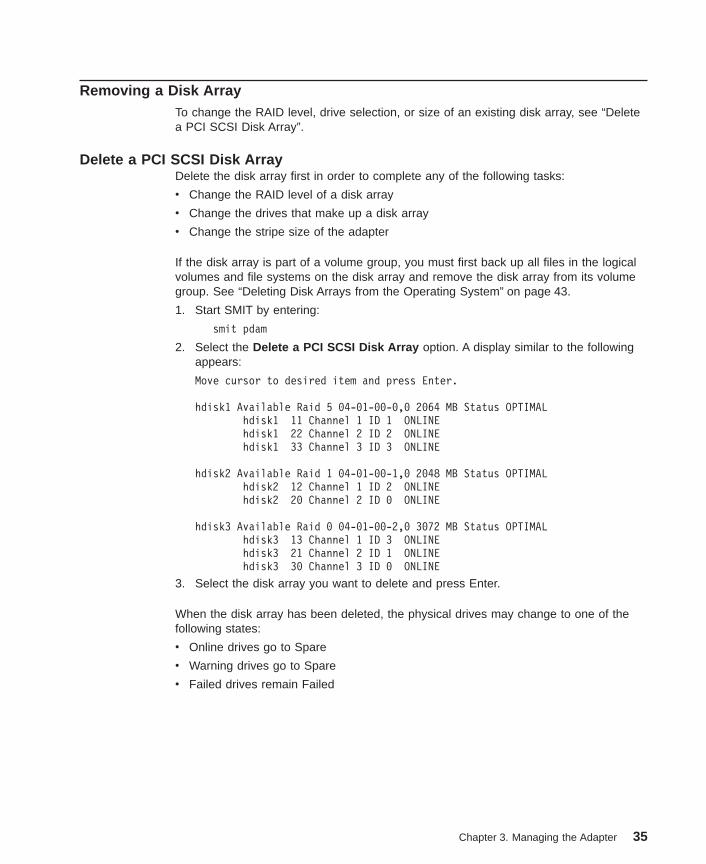
1. Start SMIT by entering:
smit pdam
2. Select the Delete a PCI SCSI Disk Array option. A display similar to the followingappears:
Move cursor to desired item and press Enter.
hdisk1 Available Raid 5 04-01-00-0,0 2064 MB Status OPTIMALhdisk1 11 Channel 1 ID 1 ONLINEhdisk1 22 Channel 2 ID 2 ONLINEhdisk1 33 Channel 3 ID 3 ONLINE
hdisk2 Available Raid 1 04-01-00-1,0 2048 MB Status OPTIMALhdisk2 12 Channel 1 ID 2 ONLINEhdisk2 20 Channel 2 ID 0 ONLINE
hdisk3 Available Raid 0 04-01-00-2,0 3072 MB Status OPTIMALhdisk3 13 Channel 1 ID 3 ONLINEhdisk3 21 Channel 2 ID 1 ONLINEhdisk3 30 Channel 3 ID 0 ONLINE
3. Select the disk array you want to delete and press Enter.
When the disk array has been deleted, the physical drives may change to one of thefollowing states:
v Online drives go to Spare
v Warning drives go to Spare
v Failed drives remain Failed
Chapter 3. Managing the Adapter 35
Reviving a Failed DriveAttention: Caution should be used when using the Revive a Failed Drive option as itmay lead to corrupted data. As an example, consider a RAID level 0 disk array that is inthe Dead state because one physical drive went to the Failed state. If the Failedphysical drive was replaced with a good drive and the Revive a Failed Drive optionwas used, the status of the disk array would change to Optimal because all of thedrives in the disk array are online. The disk array is now accessible but the data on thereplaced drive is not valid. The proper recovery in this example would have been todelete and recreate the disk array (after replacing the Failed drive) and restoring thedata from the backup copy. The Revive a Failed Drive option cannot be used on afailed drive which is part of a Degraded RAID array. A Reconstruct operation must beperformed if you wish to revive a failed drive which is part of a Degraded RAID array.
Assigning Hot Spare DrivesHot Spare drives are used to automatically replace Failed drives with drives ofequivalent capacity in a redundant RAID environment.
1. Select the Change/Show PCI SCSI RAID Drive Status option.
2. Select the Add a Hot Spare Drive option. Select the PCI 4-Channel Ultra3 SCSIRAID Adapter you want to work with and press Enter.
3. Select the drive to be the hot spare and press Enter.
The drive state will transition to Hot Spare. On subsequent drive failures, reconstructionof Failed drives occur automatically for redundant disk arrays.
Transitioning a Hot Spare Drive to a Spare Drive1. Select the Change/Show PCI SCSI RAID Drive Status option.
2. Select the Add a Spare Drive option.
3. Select the PCI 4-Channel Ultra3 SCSI RAID Adapter you want to work with andpress Enter.
4. Select the hot spare drive you want to change to spare drive and press Enter.
The hot spare drive will transition to a spare drive.
36 PCI 4-Channel Ultra3 SCSI RAID Adapter Reference Guide
Performing a Consistency Check on a Disk ArrayThe consistency check of a RAID level 5 or 5E disk array determines if the computedparity matches the actual parity on the disk array. Performing a consistency check on aRAID level 1 disk array compares the data contained on the primary copy of the datawith the secondary copy of the data. If no is specified for the Enable AutomaticConsistency Repair option, then an error will be returned if an inconsistency is found.At this point, the user can either restore the data using the most recent backup or reruncheck consistency with the Enable Automatic Consistency Repair option set to yes.In the latter case, the PCI 4-Channel Ultra3 SCSI RAID Adapter attempts to repair theparity/mirror. Note that restoring consistency may result in loss of valid data for theblocks found to be inconsistent.
To perform a consistency check on a disk array, follow these steps:
1. Select the Perform Consistency Check option.
2. Select the disk array to perform the consistency check upon. Select yes/no for theEnable Automatic Consistency Repair option and press Enter.
Note: The Check Consistency option can only be run on disk arrays that are in theOptimal state.
Reconstructing a Failed DriveYou can reconstruct a drive after replacing a Failed drive in a degraded RAID level 1, 5,or 5E disk array.
Note: Only one reconstruct at a time is supported on the PCI 4-Channel Ultra3 SCSIRAID Adapter.
To reconstruct a Failed drive, follow these steps:
1. Replace the Failed drive with a working drive.
To transition this drive to the Reconstructing state and begin the rebuild:
2. Select the Reconstruct a PCI SCSI Disk Array option.
3. Select any Spare drive you wish to rebuild onto or leave the default value of theFailed drive if it has been replaced
Note: PDAM defaults to the Failed drive when selecting a drive to rebuild. The usercan choose the default or any spare drive of equal (or greater) capacity on theadapter.
Chapter 3. Managing the Adapter 37
Change/Show PCI SCSI Disk Array ParametersThis section describes how to change the RAID level, drive selection, or size of arrayparameters on an existing disk array. If you want to change any of these values of adisk array, you must first back up the data in all logical volumes and file systems on thedisk array, delete the logical volumes and file systems from the disk array, and thenremove the disk array from its volume group before continuing. You must then deletethe disk array and recreate using the new parameters.
Attention: Failure to back up data before deleting the disk array will result in a loss ofdata.
Use the following procedure to change the RAID level, drive selection, or size of thearray of an existing disk array:
1. Back up the data if there is any data in the logical volumes or file systems on thedisk array.
2. Unmount all file systems on the disk array you want to reconfigure.
3. Delete all logical volumes and file systems from the disk array you want toreconfigure, and remove the disk array from its volume group.
4. Delete the disk array. See “Removing a Disk Array” on page 35 for moreinformation.
5. Recreate the disk array using the new parameters. See “Creating a Disk Array” onpage 29 for more information.
38 PCI 4-Channel Ultra3 SCSI RAID Adapter Reference Guide
Configuration SynchronizationConfiguration synchronization makes the configuration on the PCI 4-Channel Ultra3SCSI RAID Adapter consistent with the configuration on the disk arrays. This is usefulin cases where the configurations are out of sync. For example, when an adapter isreplaced but the user would like to continue to use the drives configured in the sameway, configuration synchronization should be used.
1. Select the Recovery Options option.
2. Select Resolve PCI SCSI RAID Adapter Configuration .
From this panel you can select:
Display/Accept Configuration ChangesAccept the Configuration on DrivesRetry the Current Configuration
To synchronize to the configuration stored on the adapter, select the Display/AcceptConfiguration Changes option. To synchronize to the configuration on the drives (forexample, adapter replacement), select the Accept the Configuration on Drives option.
The following options include:
Display/Accept Configuration ChangesIf a PCI SCSI RAID configuration conflict is detected during a bootsequence, an error will be posted in the system error log. This optionwill allow you to view any drive state change and/or any unidentifieddrives within an existing Disk Array. Once you have viewed thechanges, you may choose to accept them. Alternatively, you maymodify the existing hardware to your needs and execute the RetryCurrent Configuration option.
Accept Configuration on DrivesAllows you to synchronize the PCI SCSI RAID configuration with theconfiguration currently stored on the majority of the physical drives.This would typically be done only in the case of a PCI SCSI RAIDadapter replacement.
Note: Following an Accept Configuration on Drives option, the PCI4-Channel Ultra3 SCSI RAID Adapter automatically performs aConsistency Check with Auto-Repair on all redundant levelRAID arrays. Progress of the Consistency Check can bemonitored using the List PCI SCSI Disk Arrays option ofPDAM.
Retry Current ConfigurationAllows you to perform a configuration reset that will cause the adapterto verify that all of the physical disk drives are detected andresponding. If the adapter is unable to detect all of the physical diskswhich were previously attached to the adapter, an error is returnedand a configuration conflict will exist.
Chapter 3. Managing the Adapter 39

Clearing a ConfigurationAttention: This option should be used with extreme CAUTION. All disk arrays and dataassociated with the selected adapter may be DESTROYED! Selecting this option isequivalent to deleting all disk arrays configured on the adapter. This is an error recoveryoption normally used by your service representatives.
1. Select the Recovery Options option of the PCI SCSI Disk Array Manager panel.
2. Select Clear PCI SCSI RAID Adapter Configuration .
3. Select the adapter to clear the configuration on and press Enter.
Restoring Configuration on Replacement AdapterAttention: If the PCI 4-Channel Ultra3 SCSI RAID Adapter being replaced experiencedan abrupt failure, there may be valid data in the adapter’s non volatile write cache.
If an existing disk array configuration will be imported from the attached drives, then thewrite cache module from the adapter being replaced should be used with the newadapter. This will ensure any data which may exist in the non volatile write cachemodule is correctly written to the attached disk drives.
A configuration conflict may result when a PCI 4-Channel Ultra3 SCSI RAID Adapterwithin a configured system is replaced (possibly due to a defective adapter). Theconfiguration stored on the adapter may be out of sync with the configuration stored onthe drives. The configuration can be restored by synchronizing the adapter configurationwith the drive configuration. This can be accomplished using the Accept Configurationon Drives option under PDAM’s Recovery Options. Use the following to replace the PCI4-Channel Ultra3 SCSI RAID Adapter:
1. Start the SMIT PDAM by entering the following command:
smit pdam
2. Select the Recovery Options option.
3. Select Resolve PCI SCSI RAID Adapter Configuration option.
4. Select Accept Configuration on Drives option.
5. Select the adapter that was replaced.
Note: Following an Accept Configuration on Drives option, the PCI 4-Channel Ultra3SCSI RAID Adapter automatically performs a Consistency Check withAuto-Repair on all redundant level RAID arrays. Progress of the ConsistencyCheck can be monitored using the List PCI SCSI Disk Arrays option of PDAM.
40 PCI 4-Channel Ultra3 SCSI RAID Adapter Reference Guide
Adding Disk Arrays to the AIX Operating SystemAfter you configure a disk array using the PDAM, you can add the disk array to avolume group and create logical volumes and file systems on it before using it. Usestandard AIX procedures to do this and treat the array in the same way you would treata single disk drive. You can also access the disk array using raw IO.
Notes:
1. PCI 4-Channel Ultra3 SCSI RAID Adapter is not supported as a boot device.
2. PCI SCSI disk arrays do not support the root volume group.
Attention: The AIX Logical Volume Manager has a limit of 1016 physical partitions in aphysical volume. When creating AIX volume groups, select a physical partition sizesufficiently large so that you don’t have more than 1016 physical partitions per physicalvolume. For example, if you are creating a volume group composed of a RAID 5 diskarray composed of 5 physical disks of 2 GB each, use a physical partition size of 8 MBminimum; the default size of 4 MB will exceed the 1016 physical partition limit.
You will know you have exceeded the 1016 physical partitions per physical volume(hdisk) if you receive this message while trying to create a volume group on a diskarray (hdisk):
0516-862 mkvg: Unable to create volume group
Do not mix hdisks with different RAID characteristics in the same volume group. If youmix RAID 0 and RAID 5 hdisks, and a file system has partitions on both hdisks, a drivefailure in the RAID 0 disk array will cause you to lose all your data in the file system.
If performance is important, you should plan your volume groups and logical volumeplacement before you create them because recreating them and restoring your data canbe time-consuming. Contact your point of sale to get performance planning assistanceor more information.
The following procedure gives the basic steps required to create a file system on aconfigured disk array so that you can use it. This procedure makes the disk array itsown volume group and creates a single logical volume or file system on it. To add thedisk array to an existing volume group, extend a logical volume or file system onto it, orto change other file system options, see the procedures covered in your AIX systemdocumentation.
1. From the SMIT System Management panel, select Physical & Logical Storage .
2. From the Physical & Logical Storage panel, select Logical Volume Manager .
3. From the Logical Volume Manager panel, select Volume Group .
4. Select the Add A Volume Group option from the Volume Group screen.
5. Enter values for the Add A Volume Group panel fields, as follows:
VOLUME GROUP nameEnter a volume group name.
Chapter 3. Managing the Adapter 41
PHYSICAL VOLUME namesEnter the hard disk name of the configured disk array. Press F4to display a list of options.
Activate volume group AUTOMATICALLY at system restart?Indicate whether you want the volume to be automaticallyactivated whenever you restart the system.
ACTIVATE volume group after it is created?Indicate whether you want the volume to be automaticallyactivated when you are finished creating it (that is, when you exitSMIT).
Volume group MAJOR NUMBERGive the volume a volume number or leave this option blank.
6. Press Enter to save these values. Then press the F3 key until you return to thePhysical & Logical Storage panel.
7. Select the File Systems option from the Physical & Logical Storage panel.
8. Select the Add / Change / Show / Delete File Systems option from the FileSystems panel.
9. Select the Journaled File System option from the Add / Change / Show / DeleteFile Systems panel. A list of volume groups is displayed.
10. Select Add a Journaled File System from the Journaled File System panel.
11. Select the volume group that you just created from the list of names displayed.
12. Enter values for the Journaled File System fields, as follows:
SIZE of file systemEnter the size, in number of 512-byte blocks, that you want toassign to the file system. Any size up to the limit of the volumegroup or 2 GB can be entered, although the size will be set to amultiple of the partition size.
MOUNT POINT Enter a mount point for the file system. This is the directory youwill enter to access the file system.
Mount AUTOMATICALLY at system restart?Select yes or no, depending on whether you want this file systemmounted automatically after the system is started.
PERMISSIONS Leave this at read/write .
Mount OPTIONSEnter the mount options or leave this field blank.
13. Press Enter to create the journaled file system.
After completing this procedure, you can mount and use the newly created file system,using the specified mount point.
42 PCI 4-Channel Ultra3 SCSI RAID Adapter Reference Guide

Deleting Disk Arrays from the Operating SystemAttention: Failure to back up any data before performing this procedure could result inthe loss of all data on the disk arrays.
It is necessary to delete a disk array whenever you want to change or modify disk arrayparameters. The procedures required are basically the reverse of those used to adddisk arrays.
For each disk array you want to delete, perform the following procedure:
1. Back up any data on the disk array. There may be more than one logical volumeand file system on the drive. To find out which logical volumes or file systems areon the disk array, see “Identify Drives and Disk Arrays” on page 16.
2. Unmount any file systems on the disk array.
Delete any file systems on the disk array using the following steps:
1. Return to the Logical Volume Manager panel.
2. Select the File Systems option from the Logical Volume Manager panel.
3. Select the Add / Change / Show / Delete File Systems option from the FileSystems panel.
4. Select the Journaled File System option from the Add / Change / Show / DeleteFile Systems panel. A list of volume groups is displayed.
5. Select Delete a Journaled File System from the Journaled File System panel.
6. Select the file system to be removed.
Delete any logical volumes on the disk array using the following steps:
1. From the SMIT System Management panel, select Physical & Logical Storage .
2. From the Physical & Logical Storage panel, select Logical Volume Manager .
3. From the Logical Volume Manager panel, select Logical Volumes .
4. Select the Remove a Logical Volume option from the Logical Volumes panel.
5. Select the logical volume to be removed.
Remove the disk array from its volume group using the following steps:
1. Return to the Logical Volume Manager panel.
2. Select the Volumes Group option from the Logical Volume Manager panel.
3. Select either the Remove a Volume Group or Set Characteristics of a VolumeGroup option, depending on whether there are other physical volumes in thevolume group.
To find out which volume group the disk array is in, see “Identify Drives and DiskArrays” on page 16. Then go to “Delete a PCI SCSI Disk Array” on page 35 to deletethe disk array using PDAM.
Chapter 3. Managing the Adapter 43

Extending Logical Volumes and Disk ArraysYou can extend an existing logical volume onto a disk array just as you can with anyother disk storage device. However, you should remember that the data reliability of acombined logical volume is only as great as the reliability of its weakest part. Forexample, if you combine a RAID level 5 disk array and a RAID level 0 disk array intothe same logical volume, the resulting volume has the data redundancy protection of aRAID level 0 disk array (that is, none). Even though the RAID level 5 portion of thelogical volume has data redundancy, if the RAID level 0 portion fails, the whole volumemay become unusable, and all data on the volume will be lost. However, a RAID level 1and a RAID level 5 logical volume would offer data redundancy.
44 PCI 4-Channel Ultra3 SCSI RAID Adapter Reference Guide

Chapter 4. PCI 4-Channel Ultra3 SCSI RAID Adapter ProblemDetermination and Recovery
This chapter provides information to assist you in determining and recovering from errorconditions. The following topics are discussed in detail:
v Identifying and recovering from drive failures. If a drive attached to the PCI4-Channel Ultra3 SCSI RAID Adapter fails, procedures are provided by the PCI SCSIDisk Array Manager (PDAM) for removing and replacing the failed drive.
v Instructions on how to recover the data from the failed drive (in redundantenvironment) or restoring the data from the drive (on non-redundant environments)are included.
v Information describing the various RAID levels and how drive failures are handled byeach of the levels.
v Instructions on how to replace a PCI 4-Channel Ultra3 SCSI RAID Adapter.
v Information describing how to detect and resolve array configuration conflicts.
You may also refer to the informational error messages returned by the PCI 4-ChannelUltra3 SCSI RAID Adapter device driver. These include alertable error messages andAIX error log entries in “Messages and Error Log Templates” on page 66.
Drive Failures and Disk ArraysThe PCI 4-Channel Ultra3 SCSI RAID Adapter handles drive failures differently,depending on the RAID level involved.
Drive StatusThere are seven possible values that may be displayed for the status of a physical driveand five possible values that may be displayed for the status of a disk array.
Disk Array StatesThe state of a disk array is uniquely determined by the states of the physical drives thatmake up the disk array. Depending on the number of Failed physical drives,replacement of a Failed drive with a good drive may change the state of the disk arrayfrom Dead to Degraded or Optimal after data rebuild. When a Failed physical drive isreplaced in a Degraded disk array, the data is rebuilt onto the replaced drive before thedisk array state transitions to the Optimal.
Optimal The disk array is in good functional state.
Compressing This is a special state for RAID level 5E disk arrays only. This stateindicates that one physical drive in the array is in the Failed state.The data from the failed drive is compressed onto the Hot-spare bybeing distributed across the spare space of the remaining drives.When compression is complete the disk array indicates an Optimalstate.
45
DecompressingThis is a special state for RAID level 5E disk arrays only.Decompressing occurs on compressed RAID level 5E disk arrays. ARAID level 5E array is compressed when the disk array is Optimaland there is one physical drive in the Failed state. When a Hot-spareis added to the disk array, compressed data on the disk array isdecompressed onto the newly added Hot-spare. Whendecompressing completes the disk array will be Optimal with allphysical arrays in the Online state.
Degraded One of the physical drives that is part of a disk array is in the Failedstate.
Dead For a non-redundant disk array, this state indicates that one or morephysical drives are in the Failed state. For a redundant disk array, thisstate indicates that two or more physical drives are in the Failed state.A Dead disk array is not accessible.
Physical Disk StatesOnline The drive is part of a disk array and is in good functional state.
Spare The drive is connected to the adapter, but not configured into a diskarray. This drive is available to for the creation of a disk array.
Failed The drive was Failed by the PCI 4-Channel Ultra3 SCSI RAIDAdapter or by the user and must be replaced. A drive goes to Failedstate when one of the following conditions occur:
v Drive does not respond to selection.
v Drive failed to spin-up.
v Fail in inquiry or read capacity.
v Fail to read or write reserve area.
v Drive fails to respond to SCSI commands.
v Inquiry, capacity, serial number and SCSI ID do not matchconfiguration data stored on the adapter NVRAM.
v User failed the drive using PDAM.
Reconstruct The drive is undergoing a data reconstruction operation.
Warning The drive has set its Predictive Failure Analysis (PFA) indication.Although the drive may remain functional, this an indication that aserious failure of the drive is imminent. The severity of this statusdepends to some extent on the RAID level of the disk array.
The Warning drive should be replaced as soon as possible.
Hot Spare The drive automatically replaces an equivalent Failed drive in aredundant disk array.
Non Existent A drive location is marked as non existent if no disk was detected atthat channel/SCSI ID.
46 PCI 4-Channel Ultra3 SCSI RAID Adapter Reference Guide
Disk Array FailuresThis section contains information on disk array drive failures:
v RAID Level 0
v RAID Level 1
v RAID Level 5
v RAID Level 5E
Raid Level 0When read or write errors occur on one or more drives in a RAID level 0 disk array, thedrive state changes from Online to Failed or Warning. Follow the steps below:
1. You should attempt to back up the files on all logical volumes and file systems onthe disk array. If the error is not serious, you may be able to recover the data.
2. Regardless of whether the backup succeeds, use the PDAM to identify the diskdrive on which the error occurred.
3. Delete all the logical volumes and file systems on the disk array.
4. Remove the disk array from the volume group.
5. Replace the Failed or Warning drive and use the PDAM to revive the replaceddrive.
6. Add the disk array back to a volume group.
7. Recreate the logical volumes and file systems on it.
8. Copy data back to the restored disk array from your backup media.
Raid Level 1This section describes drive failures on a RAID level 1 disk array, and the disk arrayand drive status values that result from such failures.
Single-Drive Failures: Whenever a single drive in a RAID level 1 disk arraytransitions to the Failed state, the disk array status changes to Degraded. The diskarray remains functional because the data on the Failed drive can be accessed fromthe mirrored stripe.
Whenever a drive is marked as Failed, you should replace it as soon as possible. If aHot-spare drive was defined, the adapter may reconstruct the data on the driveautomatically. If a Hot-spare reconstruct was not initiated by the adapter, then using thePDAM, initiate a reconstruct on the failed drive following replacement. If you cannotreplace the drive immediately, back up the files on all logical volumes and file systemson the disk array and replace the drive when you can.
Multiple-Drive Failures: Whenever the second drive in a RAID level 1 disk array hasexperienced read or write errors, the adapter takes the following actions:
v If the error is a recoverable read error, then the disk array status remains Degradedand an entry is posted in the error log.
v If the error is an unrecoverable error, and the drive is the mirrored pair of a drive thatis already Failed, the drive status changes to Failed. The disk array status changesto Dead.
Chapter 4. PCI 4-Channel Ultra3 SCSI RAID Adapter Problem Determination and Recovery 47

Note: Only one Failed drive per RAID level 1 disk array is supported on the PCI4-Channel Ultra3 SCSI RAID Adapter.
Raid Level 5This section describes drive failures on a RAID level 5 disk array, and the disk arrayand drive statuses that result from such failures.
Single-Drive Failure: Whenever a single drive in a RAID level 5 disk array transitionsto the Failed state, the disk array status changes to Degraded. The disk array remainsfunctional because the data on the Failed drive can be reconstructed using parity anddata on the remaining drives.
Whenever a drive is marked as Failed, you should replace it as soon as possible. If aHot-spare drive was defined, the adapter may reconstruct the data on the driveautomatically. If a Hot-spare reconstruct was not initiated by the adapter, then using thePDAM, initiate a reconstruct on the failed drive following replacement. If you cannotreplace the drive immediately, back up the files on all logical volumes and file systemson the disk array and replace the drive as soon possible.
Multiple-Drive Failures: If a second drive in a RAID level 5 disk array experiencesread or write errors, the adapter takes the following actions:
v If the error is a recoverable read error, then the drive status remains Degraded andan entry is posted in the error log.
v If the errors are unrecoverable, the drive status changes to Failed. The disk arraystatus changes to Dead.
If the disk array status is Degraded, you will be able to reconstruct the data on the diskarray by replacing the Failed drive, and reconstructing the data on the drive. If the diskarray status is Dead, you will have to replace the Failed drives and then delete andrecreate the disk array (after deleting the logical volumes and file systems on the diskarray and removing the disk array from the volume group). You must then add the diskarray back to a volume group, recreate the logical volumes and file systems on it, andcopy data back to the restored disk array from your backup media.
Raid Level 5EThis section describes drive failures on a RAID level 5E disk array, and the disk arrayand drive statuses that result from such failures.
Single-Drive Failure: Whenever a single drive in a RAID level 5E disk arraytransitions to the Failed state, the disk array status changes to Compressing. After thedrive has successfully compressed, the disk array status changes to Optimal. The diskarray remains functional because the data from the Failed drive is compressed onto theHot-spare space on the remaining drives.
Whenever a disk array has been compressed, you should decompress it as soon aspossible. If a Hot-spare drive was defined, the adapter may decompress the data on thedrive automatically. If a Hot-spare was not defined, then you should add a Hot-spare.
48 PCI 4-Channel Ultra3 SCSI RAID Adapter Reference Guide
When the Hot-spare is added, the disk array begins decompressing the data onto theHot-spare. When the disk array has successfully decompressed, the disk array statuschanges to Optimal.
Note: Whenever the disk array is compressed and one drive fails, then the disk arraystatus changes to Degraded. The disk array remains functional because the datacan be reconstructed using parity and data remaining on the drives. If a seconddrive fails before compression completes the disk array will have a status ofDead.
Multiple-Drive Failures: Two situations may occur for multiple drive failures.
v If a second drive fails while the disk array is Compressing then the disk array statuswill change to Dead. If three or more drives fail at any time the disk array status willchange to Dead.
v If a second drive fails after the disk array has completed Compressing and has anOptimal status then the status will change to Degraded.
If the disk array status is Degraded, you will be able to reconstruct the data on the diskarray by adding a Hot-spare drive to the array. If the disk array status is Dead, you willhave to replace the Failed drives and then delete and recreate the disk array (afterdeleting the logical volumes and file systems on the disk array and removing the diskarray from the volume group). You must then add the disk array back to a volumegroup, recreate the logical volumes and file systems on it, and copy data back to therestored disk array from your backup media.
Chapter 4. PCI 4-Channel Ultra3 SCSI RAID Adapter Problem Determination and Recovery 49

Reconstructing Redundant Disk Arrays after Drive FailureReconstruction is a process used to restore a degraded RAID level 1, 5, or 5E diskarray to its Optimal state after a single drive has been replaced. During reconstruction,the adapter recalculates the data on the drive that was replaced, using data and parityfrom the other drives in the disk array. The controller then writes this data to thereplaced drive. Although RAID level 1 does not have parity, the adapter can reconstructdata on a RAID level 1 disk array by copying data from the mirrored stripe.
If a Hot-spare has been defined, the adapter automatically initiates the reconstructionprocess after a drive status changes to Failed. If a Hot-spare of appropriate capacityhad not previously been defined, the reconstruct must be initiated by the user afterreplacing the Failed drive. Once reconstruction is initiated (either by the user or theadapter), the adapter completes the following actions:
v Copies special array configuration information files to the new drive
v Recalculates the data and/or parity from the data and parity on the other disk arraydrives
v Writes the recalculated data and parity to the new drive.
The disk array remains accessible while the Reconstruction is in progress. However, insome cases (for example, if you have two Warning drives in a RAID level 5 disk array )you should stop using the logical volumes and file systems on the disk array to preventsubsequent drive failure and data loss.
Drive reconstruction may have a varying impact on system I/O performance. The diskarray continues to operate in degraded mode. The reconstruction rate is a tunableattribute that must be selected before any disk arrays are configured on the adapter.See the section on Reconstruction Rate for additional information.
If there are multiple-drive failures in a RAID level 1 or 5 disk array (at least two Faileddrives), you may not be able to reconstruct the drive data. To restore a RAID level 1 or5 disk array to a working state in this case, you need to replace the drives and recreatethe disk array (after deleting the logical volumes and file systems on the disk array andremoving the disk array from the volume group). You must then add the disk array backto a volume group, recreate the logical volumes and file systems on it, and copy databack to the restored disk array from your backup media.
Notes:
1. Only one reconstruct can be in progress at any given time on the PCI 4-ChannelUltra3 SCSI RAID Adapter. Concurrent reconstructs are not supported.
2. Allow reconstruction to complete before running diagnostics. Running diagnostics onthe PCI 4-Channel Ultra3 SCSI RAID Adapter during a reconstruct kills thereconstruction. If a reconstruction fails, it may be restarted using PDAM.
50 PCI 4-Channel Ultra3 SCSI RAID Adapter Reference Guide

The Reconstruction Rate - Low, Medium, HighThe rate at which a reconstruction occurs depends on the value of the reconstructionrate parameter. This parameter determines how much resource the adapter allocatesfor reconstructions. When the adapter reconstructs data on a drive, it divides theadapter’s internal resources between reconstruction and normal I/O operations. Asreconstruction rate increases, system I/O performance and reconstruction time maydecrease. These parameters control only the rate of data reconstruction, not totalreconstruction time.
Change Reconstruction Rate ParametersUse this procedure to change the Reconstruction Rate parameters.
Note: The Reconstruction Rate attribute may only be changed prior to the creation ofany disk arrays on the adapter. Once a disk array has been configured on anadapter, the Reconstruction Rate cannot be changed. In order to modify theReconstruction Rate , all disk arrays on the adapter must first be removed.
1. Start the SMIT PDAM:
smit pdam
2. Select the device (hdisk) name of the disk array you want.
3. Select the Change/Show IBM PCI SCSI RAID Adapter option.
4. Select an adapter when prompted.
5. Select the Reconstruction Rate option and enter the new value for this field.
6. Press Enter to make the changes and exit SMIT.
Chapter 4. PCI 4-Channel Ultra3 SCSI RAID Adapter Problem Determination and Recovery 51
Checking Consistency (Check and Repair Array Parity)
Note: The Check Consistency option applies only to RAID levels 1, 5, and 5E. RAIDlevel 0 is a non-redundant array and therefore cannot be checked and repaired.RAID level 1 does not have parity either, but a parity check compares data onthe mirrored drives. In addition, the RAID level 1, 5, or 5E disk array must be atOptimal status in order to run check consistency.
Check consistency performs the following functions:
1. Scans the disk array and checks the array parity for each block in the disk array. Ona RAID level 1 disk array, Parity Check compares the data on each mirror, stripe bystripe.
2. Repairs any array parity errors found during the parity check. On a RAID level 1disk array, the adapter changes the data on the mirror stripe to make it match thedata on the data disk. On a RAID level 5 and 5E disk arrays, the controller changesthe parity so that it is consistent with the data.
The data is not repaired if array parity errors result from corrupted data. Only the arrayparity is repaired. Array parity is used in RAID Level 5 and 5E disk arrays to enabledata to be reconstructed if a single drive fails. Checking and repairing parity helpsensure that you can recover after a drive failure.
Note: Upon creation of a disk array, if the parity/mirror is not initialized (InitializeParity=no), then the Check Consistency option encounters inconsistencies. It isrecommended that the parity/mirror be initialized at disk array creation. Thisapplies to only RAID levels 1, 5, and 5E. RAID level 0 is a non-redundant arrayand therefore cannot be initialized.
Perform Check ConsistencyAlways maintain backup files, even with RAID level 1, 5, and 5E disk arrays.
1. Start the SMIT PCI SCSI Disk Array Manager
2. Select the Perform Check Consistency option.
3. Select the device (hdisk) name of the disk array you want to check and repair.
Note: Setting the Enable Automatic Consistency Repair option to yes enablesthe adapter to attempt to repair any inconsistencies encountered.
You must run Check Consistency on each disk array separately.
4. When all the entries are correct, press Enter to perform the check on the selecteddisk arrays.
5. Repeat steps 3 through 4 as needed to check and repair additional disk arrays.
Attention: It is assumed the data is good and the parity is bad if an inconsistency isfound when repairing a RAID level 5 or 5E array. Always maintain backup files also forRAID level 1, 5, and 5E disk arrays. Backups are the most reliable method of restoringdata.
52 PCI 4-Channel Ultra3 SCSI RAID Adapter Reference Guide

Restoring and Recovering Disk ArraysDisk arrays may be restored to a working state after drive failure using severalmethods. Procedures for disk array restoration are provided for each of the RAID levelsbecause each level may have a unique recovery process. To restore a disk array, referto “Restoring a Disk Array” on page 58.
Error recovery procedures are also provided for various disk array status values. Referto the following information:
v “Delete a Spare or Failed Drive” on page 34
v “Add a Spare Drive” on page 33
v “Reviving a Failed Drive” on page 36
v “Reconstructing a Failed Drive” on page 37
Restoring a disk array is the process of returning the disk array to the Optimal stateafter a drive failure. The tasks involved depend on the RAID level of the disk array andon how many drives have Failed or have experienced errors:
v Single-drive failures in RAID levels 1, 5, and 5E are easily restored without losingdata and without shutting down the disk array.
v Multiple-drive failures, or single-drive failures on RAID level 0, are treated likenon-array drive failures in AIX. Delete the logical volumes, file systems, and volumegroups on the disk array. Replace the drive, recreate the disk array and AIX filestructures, and restore the data from the backup copy.
Note: Single-drive failures on redundant RAID Levels 1, 5, and 5E are recoverable.The user should identify the Failed drive, physically remove it from thesubsystem, and replace it with another drive. The user may then initiate areconstruct on the Failed drive. Alternatively the user may reconstruct the datausing an available Spare drive. The current Failed drive remains Failed but nolonger exists as part of the disk array. For single-drive failures on RAID level 5Edisk arrays, the disk array will compress and the disk array status changes toCompressing. After a successful compression the disk array status will change toOptimal. A Hot-spare drive should be added to decompress the disk array. Whenthe Hot-spare drive is added the adapter will automatically decompress the array.After a successful decompression, the current Failed drive remains Failed but nolonger exists as part of the array. This task is intended to be performed by thesystem administrator, and involves no reorganization or deletion of file systemsor volume groups.
You need to replace a drive when one of the following events occur:
v The AIX error log facility sends a message indicating a disk array component failure(a drive state transitioned to Failed).
v You see a disk array status other than Optimal displayed by the List all PCI SCSIRAID Arrays option.
v You see a drive status other than Online or Spare displayed by the List all PCI SCSIRAID Arrays option.
Chapter 4. PCI 4-Channel Ultra3 SCSI RAID Adapter Problem Determination and Recovery 53

The recovery tasks are summarized in the RAID Recovery Tasks Summary tables thatfollow. See “Restoring and Recovering Disk Arrays” on page 53 for more information.
RAID Level 0 Recovery Tasks Summary
Disk Array and Drive Status Recovery Steps
Disk array status is Dead 1. Delete the file systems and logical volumeson the affected disk array and remove thedisk array from the volume groups (see“Deleting Disk Arrays from the OperatingSystem” on page 43.
2. Replace failed drives.
3. Delete and recreate the disk array.
4. Create new logical volumes and filesystems on restored units (see “Adding DiskArrays to the AIX Operating System” onpage 41
5. Copy backed-up data to the restored logicalvolumes or file systems.
54 PCI 4-Channel Ultra3 SCSI RAID Adapter Reference Guide

RAID Level 1 Recovery Tasks Summary
Disk Array and Drive Status Recovery Steps
Disk array status is Optimal, one or more driveshave status of Warning.
1. If the PDAM displays two or more driveswithin a disk array that have the Warningstate, stop using all file systems and logicalvolumes on the affected disk arrays andattempt to back up all files in those logicalvolumes before continuing.
2. One at a time, fail each drive (using thePDAM) that is in the Warning state.Replace the Warning drive, and reconstructthe data on it.
Disk array status is Degraded. Drive statusshows a Failed drive.
1. Replace the Failed drive.
2. Using PDAM, reconstruct the data on thereplaced drive.
Disk array status is Dead. Drive status showstwo or more Failed drives.
1. Delete the file systems and logical volumeson the affected disk arrays, and remove thedisk arrays from their volume groups (see“Deleting Disk Arrays from the OperatingSystem” on page 43.
2. Delete the Dead disk array. The Faileddrives will remain Failed drives outside of adisk array. Delete the Failed drives from thesystem using PDAM, then physicallyreplace the Failed drives. Add new drivesback into the system as Spare drives usingPDAM. Recreate the disk array.
3. Create new logical volumes and filesystems on the restored units (see “AddingDisk Arrays to the AIX Operating System”on page 41
4. Copy backed-up data to the restored filesystems or logical volumes.
Chapter 4. PCI 4-Channel Ultra3 SCSI RAID Adapter Problem Determination and Recovery 55

RAID Level 5 Recovery Tasks Summary
Disk Array and Drive Status Recovery Steps
Disk array status is Optimal. 1. If the PDAM displays two or more driveswithin a disk array that have the Warningstate, stop using all file systems and logicalvolumes on the affected disk arrays andattempt to back up all files in those logicalvolumes before continuing.
2. One at a time, fail each drive (using thePDAM) that is in the Warning state.Replace the Warning drive, and reconstructthe data on it.
Disk array status is Degraded. Drive statusshows one Failed drive.
1. Replace the Failed drive.
2. Reconstruct the data on the Failed drive byusing the PDAM.
Disk array status is Dead. Drive status showstwo or more Failed drives.
1. Delete the file systems and logical volumeson the affected disk arrays, and remove thedisk arrays from their volume groups (see“Deleting Disk Arrays from the OperatingSystem” on page 43.
2. Delete the Dead disk array. Delete theFailed drives from the system using PDAM,then physically replace the Failed drives.Add the drives back into the system asSpare drives using PDAM. Recreate thedisk array.
3. Create new logical volumes and filesystems on the restored units (see “AddingDisk Arrays to the AIX Operating System”on page 41
4. Copy backed-up data to the restored filesystems or logical volumes.
56 PCI 4-Channel Ultra3 SCSI RAID Adapter Reference Guide

RAID Level 5E Recovery Tasks Summary
Disk Array and Drive Status Recovery Steps
Disk array status is Optimal. 1. If the PDAM displays two or more driveswithin a disk array that have the Warningstate, stop using all file systems and logicalvolumes on the affected disk arrays andattempt to back up all files in those logicalvolumes before continuing.
2. Add a Hot-spare drive to the disk array foreach drive in the Warning state. TheHot-spare drive must have a capacitygreater than or equal to the smallest diskcapacity in the disk array.
3. One at a time, fail each drive (using thePDAM) that is in the Warning state. Theadapter will initiate the reconstruct of thedata. When the reconstruct completes youmay repeat this step for each Warningdrive.
Disk array status is Degraded. Drive statusshows two Failed drives.
1. Add a Hot-spare drive to the disk array foreach drive in the Warning state. TheHot-spare drive must have a capacitygreater than or equal to the smallest diskcapacity in the disk array.
2. The adapter may begin the reconstruct ofdata after the Hot-spare is added.
Disk array status is Dead. Drive status showstwo or more Failed drives.
1. Delete the file systems and logical volumeson the affected disk arrays, and remove thedisk arrays from their volume groups (see“Deleting Disk Arrays from the OperatingSystem” on page 43.
2. Delete the Dead disk array. Delete theFailed drives from the system using PDAM,then physically replace the Failed drives.Add the drives back into the system asSpare drives using PDAM. Recreate thedisk array.
3. Create new logical volumes and filesystems on the restored units (see “AddingDisk Arrays to the AIX Operating System”on page 41
4. Copy backed-up data to the restored filesystems or logical volumes.
Chapter 4. PCI 4-Channel Ultra3 SCSI RAID Adapter Problem Determination and Recovery 57

Restoring a Disk ArrayUse the following procedure to restore a disk array:
1. Determine the degree to which the drive fault has affected the disk array. This canbe accomplished with the PDAM. This will report any drives that have had errors.
2. Start the SMIT PCI SCSI Disk Array Manager by entering the following command:
smit pdam
3. Select the List all PCI SCSI Disk Arrays option from the PCI disk array Managermenu. This will return the status of each disk array and the status of each drivewithin the disk array.
4. If a disk array status is Optimal, but one or more drives are in the Warning state,then the drive(s) has exceeded its soft error threshold. Go to “Replacing Failed orWarning Drives (RAID Levels 1, 5, and 5E)”.
5. If a disk array status is Degraded and the List all PCI SCSI RAID ARRAY optionshows the Failed drive, go to “Replacing Failed or Warning Drives (RAID Levels 1,5, and 5E)” and complete the procedure.
If a disk array status is Optimal and compressed, go to “Replacing Failed orWarning Drives (RAID Levels 1, 5, and 5E)” and complete the procedure.
6. If the disk array status is Dead, then go to “Replacing a Dead or Optimal Array” onpage 59.
Replacing Failed or Warning Drives (RAID Levels 1, 5, and 5E)Use the following procedure to replace a Failed or Warning drive in a RAID level 1, 5,or 5E disk array. If a drive in a disk array has a status of Failed, the disk array will havea status of Degraded. For RAID level 5E disk arrays, compressed disk arrays with oneFailed drive will have a status of Degraded while compressed disk arrays with no Faileddrives will have a status of Optimal. If one or more drives in a disk array have a statusof Warning, the disk array status will remain Optimal.
1. Start the PDAM by entering the following command:
smit pdam
2. Select the Change/Show PCI SCSI Drive Status option.
3. Locate the Failed or Warning drive.
4. Replace the drive with a good drive of equal or greater capacity. For RAID level 5Edisk arrays, add a Hot-spare drive with a good drive of equal or greater capacity.
Attention: If the replaced drive was a Warning drive, it is necessary to fail the drivebefore continuing to the next step. See the Fail a Drive section in Chapter 4. Do notfail more than one drive at a time, even if you need to replace more than one drive.Fail and reconstruct the drives one at a time.
Note: If a service request number (SRN) is needed for the device, it will benecessary to run hardware diagnostics. See the Diagnostic Information forMultiple Bus Systems for complete instructions on running systemdiagnostics.
5. After you have physically replaced the drive, initiate a reconstruct on the replaceddrive. Alternatively, the user may reconstruct onto any Spare drive. The Failed drivewill remain Failed but will no longer be part of the disk array. The status of thereplaced drive should change to Reconstructing.
58 PCI 4-Channel Ultra3 SCSI RAID Adapter Reference Guide

For RAID level 5E disk arrays, after adding the Hot-spare drive the disk array will doone of the following:
v Compressed disk arrays with an Optimal status will decompress. Aftersuccessfully decompressing the disk array will be decompressed with a status ofOptimal.
v Compressed disk arrays with one failed drive will have a status of Degraded. Thedisk array will begin reconstructing. After successfully reconstructing the diskarray will be compressed with a status of Optimal.
Note: If reconstruction does not start automatically (a Hot-spare was not in place),select the Reconstruct an IBM PCI SCSI Disk Array option from the PDAMmain menu to initiate reconstruction manually.
Wait for reconstruction to finish. The drive status of the replaced drive changes toOnline, and the status of the affected disk array changes to Optimal.
6. After you have replaced and reconstructed all the Failed drives, exit PDAM.
Attention: Do not use this procedure to replace drives in a RAID level 0 array. For theRAID level 0 procedure, see “Replacing a Dead or Optimal Array”. If there are two ormore drives that need to be replaced, stop using all logical volumes and file systems onthe disk array immediately. Back up all logical volumes on the disk array beforecontinuing.
Replacing a Dead or Optimal ArrayThis procedure is essentially the same procedure you would use to replace a Failednon-array disk drive in the AIX operating system. Use this procedure to restore diskarrays in the following circumstances:
v All RAID level 0 disk arrays with a status of Dead or Optimal.
Note: A RAID level 0 disk array that has a drive in the Warning state will be in theOptimal state. A RAID level 0 disk array that has a drive in the Failed state willbe in the Dead state.
v A RAID level 1 disk array with a status of Dead.
v A RAID level 5 disk array with a status of Dead.
v A RAID level 5E disk array with a status of Dead.
1. For a RAID level 0 disk array that is Optimal, attempt to back up the files in all thelogical volumes and file systems on the disk array.
2. Remove all logical volumes and file systems on the disk array affected by the baddrive. See “Deleting Disk Arrays from the Operating System” on page 43.
3. Start the PCI SCSI Disk Array Manager by entering the following command:
smit pdam
4. Select the Change/Show PCI SCSI Drive Status option.
5. Locate the drive that the PDAM displays as Failed or Warning.
Note: If the drive is in the Warning state, fail the drive manually before continuing.See “Reviving a Failed Drive” on page 36.
Chapter 4. PCI 4-Channel Ultra3 SCSI RAID Adapter Problem Determination and Recovery 59

6. Delete the disk array. Select the Delete a PCI SCSI Disk Array option from thePDAM main menu. Select the appropriate disk array and press Enter.
7. The Failed drives will remain Failed outside of the disk array. Select the Remove aFailed Drive option from PDAM and remove the Failed drive from the system.Physically replace the drives, adding them back to the system using the Add aSpare Drive option.
8. Recreate the disk array. Use the Create a PCI SCSI Disk Array option from thePDAM main menu.
9. Create new logical volumes and file systems on the restored disk arrays (see“Adding Disk Arrays to the AIX Operating System” on page 41
10. Copy backed-up data back to the restored logical volumes and file systems.
Replacing the PCI 4-Channel Ultra3 SCSI RAID AdapterAttention: If the PCI 4-Channel Ultra3 SCSI RAID Adapter being replaced experiencedan abrupt failure, there may be valid data in the adapter’s non volatile write cache.
If an existing disk array configuration will be imported from the attached drives, then thewrite cache module from the adapter being replaced should be used with the newadapter. This will ensure any data which may exist in the non volatile write cachemodule is correctly written to the attached disk drives.
A configuration conflict may result when a PCI 4-Channel Ultra3 SCSI RAID Adapterwithin a configured system is replaced (possibly due to a defective adapter). Theconfiguration stored on the adapter may be out of sync with the configuration stored onthe drives. The configuration can be restored by synchronizing the adapter configurationwith the drive configuration. This can be accomplished using the Accept Configurationon Drives option under PDAM’s Recovery Options . Use the following to replace thePCI 4-Channel Ultra3 SCSI RAID Adapter:
1. Start the SMIT PDAM by entering the following command:
smit pdam
2. Select the Recovery Options option.
3. Select Resolve PCI SCSI RAID Adapter Configuration option.
4. Select Accept Configuration on Drives option.
5. Select the adapter that was replaced.
Note: Following an Accept Configuration on Drives option, the PCI 4-Channel Ultra3SCSI RAID Adapter will automatically perform a Consistency Check withAuto-Repair on all redundant level RAID arrays. Progress of the ConsistencyCheck can be monitored using the List PCI SCSI Disk Arrays option of PDAM.
60 PCI 4-Channel Ultra3 SCSI RAID Adapter Reference Guide
Detecting and Resolving Array Configuration ConflictsAn array configuration conflict exists when, during adapter configuration, the adapter isunable to detect an Online, Warning, Spare, Hot-spare disk drive, or when a drive in adisk array is moved to another location. All disk arrays (hdisks) associated with theadapter will remain in the Defined state when this condition occurs. An arrayconfiguration conflict can only exist following adapter configuration. It is, therefore, mostlikely to occur during system reboot, but can also been seen if the adapter is configuredduring runtime (for example, changed from the Defined to Available state). No PDAMoperations are supported until the configuration conflict is resolved. Attempting toperform any PDAM operation will result in the following error:
scraid0 A conflicting Disk Array configuration has beendetected. Please proceed to the 'Display/AcceptConfiguration Changes' option under the Recovery Optionspanel to resolve.<#0106>0016 - RAID Adapter command has failed.
Also, the following message is displayed and mail is sent to the root user when theconflict is first detected:
A condition has been detected that requires immediateattention. A physical disk drive previously configured onthe IBM PCI SCSI RAID adapter scraid0 was not detectedduring adapter configuration. The physical disk haseither been removed or is not detectable. Proceed to theIBM PCI SCSI Disk Array Manager Recovery Options whereyou can either accept that the drive is missing(Display/Accept Configuration Changes), or attempt againto detect the disk (Retry Current Configuration). Untilone of these options is successfully executed, no logicalRAID disks will be made available on this adapter.
Chapter 4. PCI 4-Channel Ultra3 SCSI RAID Adapter Problem Determination and Recovery 61

An entry is also posted to the system error log indicating an array configuration conflictexists. The error log entry appears as follows:
9A1495A2 0308113896 U H scraid0 ARRAY CONFIGURATIONERROR
The error log entry in its expanded form appears as follows:
LABEL: SCSI_ARRAY_ERR6IDENTIFIER: 9A1495A2
Date/Time:Fri Mar 8 11:38:38Sequence Number: 9Machine Id: 00300001C400Node Id: droolClass: HType: UNKNResource Name: scraid0Resource Class: adapterResource Type: 14102e00Location: 04-07VPD:
Part Number.................12345678EC Level....................1234567890Serial Number...............12345678FRU Number..................12345678Manufacturer................IBM000Displayable Message.........PCIRAIDiagnostic Level............01Device Driver Level.........01Loadable Microcode Level....96064!ROS Level and ID............ P10809
DescriptionARRAY CONFIGURATION ERROR
Probable CausesARRAY COMPONENT UNDETECTABLE
Failure CausesDISK DRIVECABLE LOOSE OR DEFECTIVESCSI BACKPLANESCSI REPEATER
Recommended ActionsPERFORM DISK ARRAY MANAGER RECOVERY ACTIONS
Detail DataSENSE DATA0000 0052 0000 0708 0000 0000 0000 0000 0000 0000 00000000 0000 0000 0000 0000
Any of the following indicate the presence of an array configuration conflict: error fromPDAM, alertable message, or error log entry.
62 PCI 4-Channel Ultra3 SCSI RAID Adapter Reference Guide
Resolving Disk Array Configuration ConflictsAn action must be taken to resolve the conflict when an array configuration conflictoccurs. No disk arrays configured on the adapter are available to the system until theconflict is resolved.
Note: The conflict should be handled as described in the “Replacing the PCI 4-ChannelUltra3 SCSI RAID Adapter” on page 60 if an array configuration conflict occurssubsequent to an adapter replacement. An Array configuration conflict resultingfrom an adapter replacement should not be resolved by synchronizing to theconfiguration on the adapter.
If the disk drive(s) which was not detected was part of an array, the array(s) associatedwith the disk drive(s) and its contents are displayed along with the status of the arrayprior to the conflict being detected. The location of the undetected disk drive and thestate previous to being undetected are included.
The following information is displayed:
hdisk2 Raid 5 04-07-00-0,0 2144 MB Status OPTIMALhdisk2 20 Channel 2 ID 0 ONLINEhdisk2 21 Channel 2 ID 1 ONLINEhdisk2 25 Channel 2 ID 5 ONLINE
Channel 2 ID 0 indicates change from status ONLINE tostatus FAILED DRIVE
Once it has been determined which specific disk drives are involved in the arrayconfiguration conflict, take the following actions to resolve the conflict:
Retry Current Configuration1. Select the Recovery Options option of the PDAM
2. Select the Resolve PCI SCSI RAID Adapter Configuration option.
3. Select Retry Current Configuration.
This action causes the adapter to attempt to detect the missing disk drives. This optionwould be selected after making some adjustment to the hardware that may affect theadapter’s ability to detect the disk drive; for example, powering on an external diskenclosure or reattaching a loose cable connection. If the adapter is successful indetecting the missing disk drives, then a good completion is indicated by this option, alldisk arrays associated with the adapter are configured (for example, made Available),and the conflict is resolved. If the adapter is not successful in detecting the missing diskdrives, then the array configuration conflict has not been resolved. See “Messages andError Log Templates” on page 66 or contact your service representative.
Chapter 4. PCI 4-Channel Ultra3 SCSI RAID Adapter Problem Determination and Recovery 63

Accept Configuration Changes1. Select the Recovery Options option of the PDAM.
2. Select Resolve PCI SCSI RAID Adapter Configuration .
3. Select Display/Accept Configuration Changes .
4. Select the adapter reporting the conflict.
5. Change the Display only option to NO.
The array configuration is updated to reflect an Online, Spare, or Hot-spare disk drive isnow in the Failed state. If any disk arrays are affected by failed drives, the state of thatarray is updated to reflect the disk failure. If any hard configured drives have beenrelocated within the channel then their new location is updated. All Optimal andDegraded disk arrays are brought to the Available state, and the conflict is resolved.
User action is required to resolve array configuration conflicts. This allows the user toprevent arrays from becoming Failed or Degraded for reasons such as neglecting tosupply power to a disk enclosure or connecting an SCSI cable. In these instances, thefailure can be remedied without an array having become Degraded or Failed, and anunnecessary reconstruct operation may be avoided.
Auto RearrangeAttention: This option should be used with CAUTION. Incorrect use of this option canresult in drives marked failed and disk arrays marked dead. If this occurs due toimproper use of auto rearrange, put the moved drives back to their original locationsand retry the current configuration.
Auto rearrange allows physical drives that are part of a disk array to be moved to otherlocations on the same channel when the adapter is in the Defined state. During adapterconfiguration, a configuration conflict occurs. See “Accept Configuration Changes” toaccept the new drive locations.
The PCI 4-Channel Ultra3 SCSI RAID Adapter supports auto rearrange when thefollowing rules are followed:
1. The physical drives part of a disk array are moved when the adapter is in theDefined state.
2. The new location for the drive moved is on the same channel as its old location.
3. Drives are not removed or added to any channels on the adapter during autorearrange.
4. Only drives part of a disk array can be moved and recognized at adapterconfiguration time.
64 PCI 4-Channel Ultra3 SCSI RAID Adapter Reference Guide
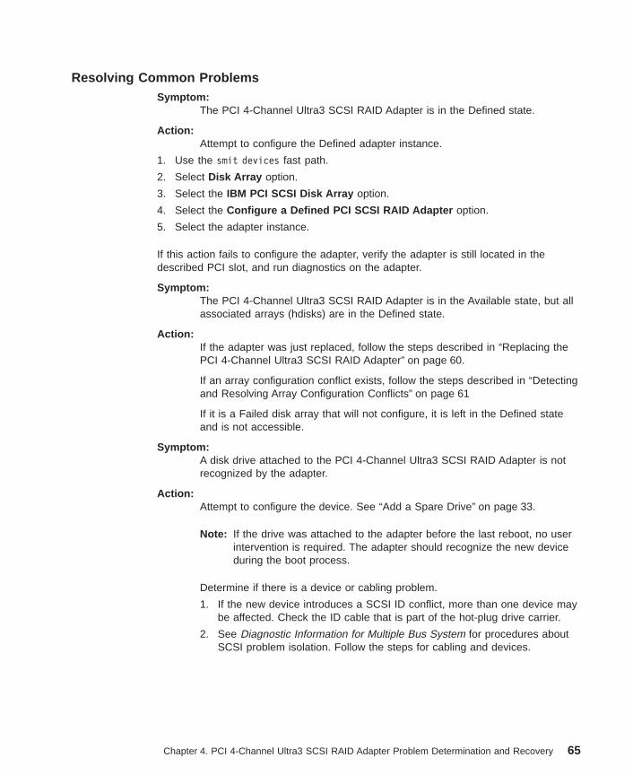
Resolving Common ProblemsSymptom:
The PCI 4-Channel Ultra3 SCSI RAID Adapter is in the Defined state.
Action:Attempt to configure the Defined adapter instance.
1. Use the smit devices fast path.
2. Select Disk Array option.
3. Select the IBM PCI SCSI Disk Array option.
4. Select the Configure a Defined PCI SCSI RAID Adapter option.
5. Select the adapter instance.
If this action fails to configure the adapter, verify the adapter is still located in thedescribed PCI slot, and run diagnostics on the adapter.
Symptom:The PCI 4-Channel Ultra3 SCSI RAID Adapter is in the Available state, but allassociated arrays (hdisks) are in the Defined state.
Action:If the adapter was just replaced, follow the steps described in “Replacing thePCI 4-Channel Ultra3 SCSI RAID Adapter” on page 60.
If an array configuration conflict exists, follow the steps described in “Detectingand Resolving Array Configuration Conflicts” on page 61
If it is a Failed disk array that will not configure, it is left in the Defined stateand is not accessible.
Symptom:A disk drive attached to the PCI 4-Channel Ultra3 SCSI RAID Adapter is notrecognized by the adapter.
Action:Attempt to configure the device. See “Add a Spare Drive” on page 33.
Note: If the drive was attached to the adapter before the last reboot, no userintervention is required. The adapter should recognize the new deviceduring the boot process.
Determine if there is a device or cabling problem.
1. If the new device introduces a SCSI ID conflict, more than one device maybe affected. Check the ID cable that is part of the hot-plug drive carrier.
2. See Diagnostic Information for Multiple Bus System for procedures aboutSCSI problem isolation. Follow the steps for cabling and devices.
Chapter 4. PCI 4-Channel Ultra3 SCSI RAID Adapter Problem Determination and Recovery 65

Messages and Error Log TemplatesThis section contains alertable messages and error log templates.
Temporary RAID Adapter ErrorF0>IDENTIFIER 51F6CEBELabel: SCSI_ARRAY_ERR1Class: HType: TEMPLoggable: YES Reportable: YES Alertable: NO
DescriptionADAPTER ERROR
Probable CausesADAPTER MICROCODEADAPTER HARDWARE
Failure CausesADAPTER MICROCODEADAPTER HARDWARE
Recommended ActionsPERFORM PROBLEM DETERMINATION PROCEDURES
Detail DataSENSE DATA
66 PCI 4-Channel Ultra3 SCSI RAID Adapter Reference Guide
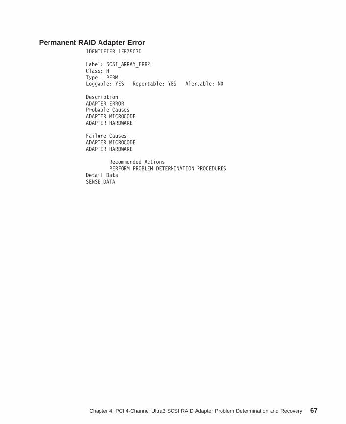
Permanent RAID Adapter ErrorIDENTIFIER 1EB75C3D
Label: SCSI_ARRAY_ERR2Class: HType: PERMLoggable: YES Reportable: YES Alertable: NO
DescriptionADAPTER ERRORProbable CausesADAPTER MICROCODEADAPTER HARDWARE
Failure CausesADAPTER MICROCODEADAPTER HARDWARE
Recommended ActionsPERFORM PROBLEM DETERMINATION PROCEDURES
Detail DataSENSE DATA
Chapter 4. PCI 4-Channel Ultra3 SCSI RAID Adapter Problem Determination and Recovery 67

Temporary Array SCSI Bus ErrorIDENTIFIER 1D57AC2F
Label: SCSI_ARRAY_ERR3Class: HType: TEMPLoggable: YES Reportable: YES Alertable: NO
DescriptionSCSI BUS ERROR
Probable CausesSCSI BACKPLANESCSI REPEATERCABLEDISK DRIVE ELECTRONICS
Failure CausesSCSI BACKPLANESCSI REPEATERCABLE LOOSE OR DEFECTIVEDISK DRIVE ELECTRONICS
Recommended ActionsPERFORM PROBLEM DETERMINATION PROCEDURES
Detail DataSENSE DATA
68 PCI 4-Channel Ultra3 SCSI RAID Adapter Reference Guide
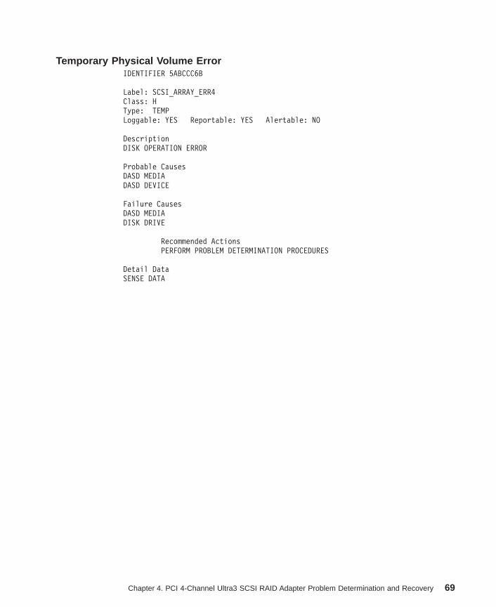
Temporary Physical Volume ErrorIDENTIFIER 5ABCCC6B
Label: SCSI_ARRAY_ERR4Class: HType: TEMPLoggable: YES Reportable: YES Alertable: NO
DescriptionDISK OPERATION ERROR
Probable CausesDASD MEDIADASD DEVICE
Failure CausesDASD MEDIADISK DRIVE
Recommended ActionsPERFORM PROBLEM DETERMINATION PROCEDURES
Detail DataSENSE DATA
Chapter 4. PCI 4-Channel Ultra3 SCSI RAID Adapter Problem Determination and Recovery 69
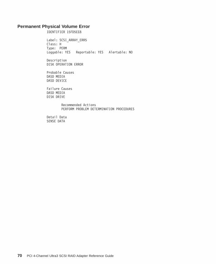
Permanent Physical Volume ErrorIDENTIFIER 15FD5EE8
Label: SCSI_ARRAY_ERR5Class: HType: PERMLoggable: YES Reportable: YES Alertable: NO
DescriptionDISK OPERATION ERROR
Probable CausesDASD MEDIADASD DEVICE
Failure CausesDASD MEDIADISK DRIVE
Recommended ActionsPERFORM PROBLEM DETERMINATION PROCEDURES
Detail DataSENSE DATA
70 PCI 4-Channel Ultra3 SCSI RAID Adapter Reference Guide

Array Configuration ErrorIDENTIFIER 9A1495A2
Label: SCSI_ARRAY_ERR6Class: HType: UNKNLoggable: YES Reportable: YES Alertable: NO
DescriptionARRAY CONFIGURATION ERROR
Probable CausesARRAY COMPONENT UNDETECTABLE
Failure CausesDISK DRIVECABLE LOOSE OR DEFECTIVESCSI BACKPLANESCSI REPEATER
Recommended ActionsPERFORM DISK ARRAY MANAGER RECOVERY ACTIONS
Detail DataSENSE DATA
Chapter 4. PCI 4-Channel Ultra3 SCSI RAID Adapter Problem Determination and Recovery 71

Array Component FailureIDENTIFIER F084AF4B
Label: SCSI_ARRAY_ERR7Class: HType: UNKNLoggable: YES Reportable: YES Alertable: NO
DescriptionARRAY COMPONENT FAILURE
Probable CausesDASD DEVICECABLESCSI BACKPLANESCSI REPEATER
Failure CausesDISK DRIVECABLE LOOSE OR DEFECTIVESCSI BACKPLANESCSI REPEATER
Recommended ActionsPERFORM PROBLEM DETERMINATION PROCEDURES
Detail DataSENSE DATA
72 PCI 4-Channel Ultra3 SCSI RAID Adapter Reference Guide

Temporary Unknown Software FailureIDENTIFIER DF7F0DED
Label: SCSI_ARRAY_ERR8Class: SType: TEMPLoggable: YES Reportable: YES Alertable: NO
DescriptionSOFTWARE PROGRAM ERROR
Probable CausesSOFTWARE PROGRAMADAPTER MICROCODE
Failure CausesSOFTWARE PROGRAMADAPTER MICROCODE
Recommended ActionsPERFORM PROBLEM DETERMINATION PROCEDURES
Detail DataSENSE DATASENSE DATA
Chapter 4. PCI 4-Channel Ultra3 SCSI RAID Adapter Problem Determination and Recovery 73

Recovered RAID Adapter ErrorIDENTIFIER 8AC43378
Label: SCSI_ARRAY_ERR9Class: HType: TEMPLoggable: YES Reportable: YES Alertable: NO
DescriptionADAPTER ERROR
Probable CausesDASD DEVICECABLESCSI BACKPLANESCSI REPEATER
Failure CausesDISK DRIVECABLE LOOSE OR DEFECTIVESCSI BACKPLANESCSI REPEATER
Recommended ActionsPERFORM PROBLEM DETERMINATION PROCEDURES
Detail DataSENSE DATA
74 PCI 4-Channel Ultra3 SCSI RAID Adapter Reference Guide
Alertable MessagesSCSI_ARRAY_ERR6A condition has been detected that requires immediateattention. A physical disk drive previously configured onthe IBM PCI SCSI RAID adapter scraidN was not detectedduring adapter configuration.The physical disk has either been removed or is notdetectable. Proceed to the IBM PCI SCSI Disk ArrayManager Recovery Options where you can either accept thatthe drive is missing (Display/Accept ConfigurationChanges), or attempt again to detect the disk (RetryCurrent Configuration). Until one of these options issuccessfully executed, no logical RAID disks will be madeavailable on this adapter.SCSI_ARRAY_ERR7A condition has been detected that requires immediateattention. A physical disk drive that is part of alogical RAID disk configured on the IBM PCI SCSI RAIDadapter scraidN has failed. The corresponding logicalRAID disk is now either degraded or offline. Proceed tothe List IBM PCI SCSI Disk Arrays option in the IBM PCISCSI Disk Array Manager to determine which physical diskhas failed and if a hotspare rebuild has been initiated.
See “Resolving Disk Array Configuration Conflicts” on page 63 for more information.
Chapter 4. PCI 4-Channel Ultra3 SCSI RAID Adapter Problem Determination and Recovery 75

76 PCI 4-Channel Ultra3 SCSI RAID Adapter Reference Guide

Appendix. Notices
This information was developed for products and services offered in the U.S.A.
The manufacturer may not offer the products, services, or features discussed in thisdocument in other countries. Consult the manufacturer’s representative for informationon the products and services currently available in your area. Any reference to themanufacturer’s product, program, or service is not intended to state or imply that onlythat product, program, or service may be used. Any functionally equivalent product,program, or service that does not infringe any intellectual property right of themanufacturer may be used instead. However, it is the user’s responsibility to evaluateand verify the operation of any product, program, or service.
The manufacturer may have patents or pending patent applications covering subjectmatter described in this document. The furnishing of this document does not give youany license to these patents. You can send license inquiries, in writing, to themanufacturer.
The following paragraph does not apply to the United Kingdom or any countrywhere such provisions are inconsistent with local law: THIS MANUAL ISPROVIDED ″AS IS″ WITHOUT WARRANTY OF ANY KIND, EITHER EXPRESSED ORIMPLIED, INCLUDING, BUT NOT LIMITED TO, THE IMPLIED WARRANTIES OFNON-INFRINGEMENT, MERCHANTABILITY OR FITNESS FOR A PARTICULARPURPOSE. Some states do not allow disclaimer of express or implied warranties incertain transactions; therefore, this statement may not apply to you.
This information could include technical inaccuracies or typographical errors. Changesare periodically made to the information herein; these changes will be incorporated innew editions of the publication. The manufacturer may make improvements and/orchanges in the product(s) and/or the program(s) described in this publication at anytime without notice.
Information concerning products made by other than the manufacturer was obtainedfrom the suppliers of those products, their published announcements or other publiclyavailable sources. The manufacturer has not tested those products and cannot confirmthe accuracy of performance, compatibility or any other claims related to products madeby other than the manufacturer. Questions on the capabilities of products made by otherthan the manufacturer should be addressed to the suppliers of those products.
77

78 PCI 4-Channel Ultra3 SCSI RAID Adapter Reference Guide

Index
Aabout this book vAdapter, managing the PCI 4-Channel Ultra3 SCSI
RAID 27adapter overview 1add a spare drive 33adding disk arrays to the AIX operating system 41alertable messages 75array, disk 10array, replacing a dead or optimal 59array component failure 72array configuration conflicts, detecting and resolving 61array configuration error 71array manager, PCI SCSI 11array manager, PCI SCSI disk 11array overview, disk 12array parameters, disk 12arrays, disk 1arrays, identify drives and disk 16assigning hot spare drives 36
Ccache, non-volatile on board write 11change reconstruction rate parameters 51change/show PCI SCSI disk array parameters 38checking consistency (check and repair array parity) 52clearing a configuration 40common problems, resolving 65configuration, clearing a 40configuration synchronization 39consistency, perform check 52creating a disk array 29
Ddelete a PCI SCSI disk array 35delete a spare or failed drive 34deleting disk arrays from the operating system 43detecting and resolving array configuration conflicts 61device names and location codes, disk array 16disk array 10disk array, creating a 29disk array, delete a PCI SCSI 35disk array, performing a consistency check on a 37disk array, removing a 35disk array, restoring a 58disk array configuration conflicts, resolving 63disk array device names and location codes 16disk array failures 47
Raid level 0 47Raid level 1 47Raid level 5 48Raid level 5E 48
disk array manager, starting the PCI SCSI 28disk array ODM information 17
device class, subclass, and type 17device location code 18device parent 18PCI 4-Channel Ultra3 SCSI RAID Adapter AIX
configuration 18disk array overview 12disk array parameters 12disk array states 31, 45disk arrays 1disk arrays, identify drives and 16disk arrays, restoring and recovering 53disk drives, SCSI 10drive, reconstructing a failed 37drive failures and disk arrays 45drive status 45drive status, modifying and displaying 31drives, SCSI disk 10drives and disk arrays, identify 16
Eextending logical volumes and disk arrays 44
Ffail a drive 34failed drive, reviving a 36failures, disk array 47features
PCI 4-Channel Ultra3 SCSI RAID Adapter 10
Hhot spare drives, assigning 36
Iidentify drives and disk arrays 16information, disk array ODM 17installing a PCI 4-Channel Ultra3 SCSI RAID Adapter
software update 24procedure 24
installing an PCI 4-Channel Ultra3 SCSI RAID Adapteron AIX Version 4 21
Prerequisite 22procedure 22
installing the PCI 4-Channel Ultra3 SCSI RAID Adaptersoftware 21
Llevels, RAID 3location codes, disk array device names and 16logical volumes and disk arrays, extending 44
79

Mmanager, PCI SCSI disk array 11managing the PCI 4-Channel Ultra3 SCSI RAID
Adapter 27Procedure 27
messages and error log templates 66alertable messages 75array component failure 72array configuration error 71permanent physical volume error 70permanent RAID adapter error 67recovered RAID adapter error 74temporary array SCSI bus error 68temporary physical volume error 69temporary RAID adapter error 66temporary unknown software failure 73
modifying and displaying drive status 31
Nnames and location codes, disk array device 16non-volatile on board write cache 11Notices 77
Ooverview, adapter 1overview, disk array 12
Pparameters, disk array 12PCI 4-Channel Ultra3 SCSI RAID Adapter 10
features 10PCI 4-Channel Ultra3 SCSI RAID Adapter, replacing
the 60PCI 4-Channel Ultra3 SCSI RAID Adapter problem
determination and recovery 45PCI SCSI disk array manager 11PCI SCSI disk array parameters, change/show 38perform check consistency 52performing a consistency check on a disk array 37permanent physical volume error 70permanent RAID adapter error 67physical disk states 32, 46preface vproblem determination and recovery, PCI 4-Channel
Ultra3 SCSI RAID Adapter 45
RRAID levels 3
RAID level 0 4RAID level 1 5RAID level 5 6RAID level 5E 8
Reader’s Comments 81reconstructing a failed drive 37reconstructing redundant disk arrays after drive
failure 50
reconstructing redundant disk arrays after drivefailure 50 (continued)
the reconstruction rate - low, medium, high 51recovered RAID adapter error 74related publications vremoving a disk array 35replacing a dead or optimal array 59replacing failed or warning drives (RAID levels 1, 5, and
5E) 58replacing the PCI 4-Channel Ultra3 SCSI RAID
Adapter 60resolving common problems 65resolving disk array configuration conflicts 63
accept configuration changes 64auto rearrange 64retry current configuration 63
restoring a disk array 58restoring and recovering disk arrays 53restoring configuration on replacement adapter 40reviving a failed drive 36
SSCSI disk array manager, PCI 11SCSI disk drives 10SCSI RAID Adapter on AIX Version 4, installing an PCI
4-Channel Ultra3 21software, installing the PCI 4-Channel Ultra3 SCSI RAID
Adapter 21software installation, verifying the PCI 4-Channel Ultra3
SCSI RAID Adapter 25starting the PCI SCSI disk array manager 28synchronization, configuration 39
Ttemplates, messages and error log 66temporary array SCSI bus error 68temporary physical volume error 69temporary RAID adapter error 66temporary unknown software failure 73trademarks vtransitioning a hot spare drive to a spare drive 36
Uupdate, Installing a PCI 4-Channel Ultra3 SCSI RAID
Adapter software 24
Vverifying the PCI 4-Channel Ultra3 SCSI RAID Adapter
software installation 25view the current disk array status 33
Wwrite cache, non-volatile on board 11
80 PCI 4-Channel Ultra3 SCSI RAID Adapter Reference Guide

Reader’s Comments — We’d Like to Hear From You
PCI 4-Channel Ultra3 SCSI RAID Adapter
Form Number: SA23-1239-00
Overall how satisfied are you with the information in this book?
VerySatisfied
Satisfied Neutral Dissatisfied VeryDissatisfied
Overall Satisfaction h h h h h
How satisfied are you that the information in this book is:
VerySatisfied
Satisfied Neutral Dissatisfied VeryDissatisfied
Accurate h h h h h
Complete h h h h h
Easy to find h h h h h
Easy to understand h h h h h
Well organized h h h h h
Applicable to your tasks h h h h h
Please tell us how we can improve this book:
Thank you for your response. May we contact you? h Yes h No
When you send comments to us, you grant us a nonexclusive right to use ordistribute your comments in any way we believe appropriate without incurringany obligation to you.
81
Fold and Tape
Fold and Tape
Please do not Staple
Please do not Staple
Fold and Tape
Fold and Tape
Information DevelopmentDepartment H6DS-956111400 Burnet RoadAustin, TX 78758-3493
Cut or FoldAlong Line
Cut or FoldAlong Line
BUSINESS REPLY MAIL
NO POSTAGENECESSARYIF MAILED IN THEUNITED STATES
POSTAGE WILL BE PAID BY ADDRESSEE
82 PCI 4-Channel Ultra3 SCSI RAID Adapter Reference Guide


Part Number: 09P1950
Printed in the United States of Americaon recycled paper containing 10%recovered post-consumer fiber.
October 2000
SA23-1239-00
(1P)
P/N:
09P1
950