diseño asic test test de circuitos integrados. diseño asic test Índice i: introducción al test...
Post on 20-Dec-2015
272 views
TRANSCRIPT

Diseño ASIC TEST
Test de CircuitosTest de CircuitosIntegradosIntegrados
Diseño ASIC TEST
ÍndiceÍndice
I: Introducción al Test de Circuitos Integrados
II: Métodos de Test III: Design for testability
Diseño ASIC TEST
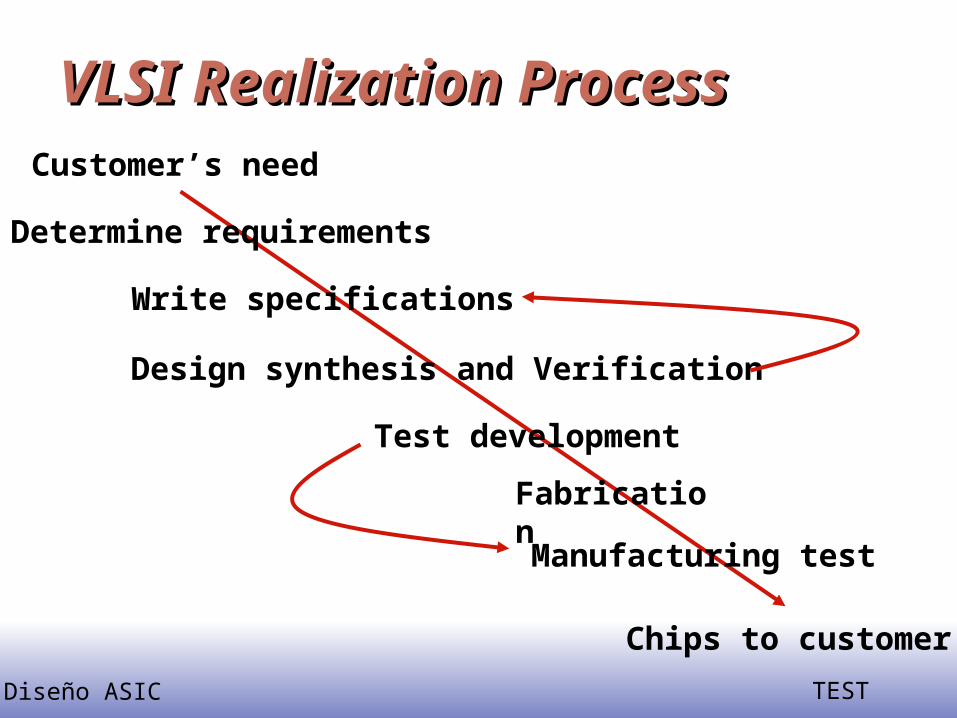
VLSI Realization ProcessVLSI Realization Process
Determine requirements
Write specifications
Design synthesis and Verification
FabricationManufacturing test
Chips to customer
Customer’s need
Test development

Diseño ASIC TEST
DefinitionsDefinitions Design synthesis: Given an I/O function, develop a
procedure to manufacture a device using known materials and processes.
Verification: Predictive analysis to ensure that the synthesized design, when manufactured, will perform the given I/O function.
Test: A manufacturing step that ensures that the physical device, manufactured from the synthesized design, has no manufacturing defect.
Diseño ASIC TEST
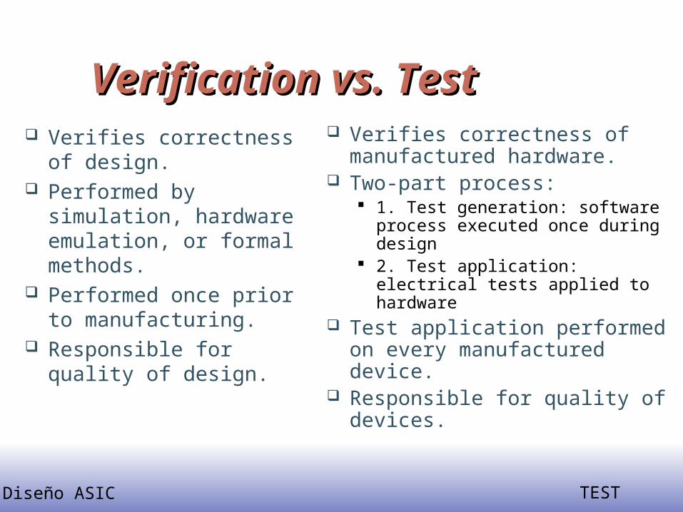
Verification vs. Test Verification vs. Test Verifies correctness of
design. Performed by
simulation, hardware emulation, or formal methods.
Performed once prior to manufacturing.
Responsible for quality of design.
Verifies correctness of manufactured hardware.
Two-part process: 1. Test generation: software
process executed once during design
2. Test application: electrical tests applied to hardware
Test application performed on every manufactured device.
Responsible for quality of devices.

Diseño ASIC TEST
Roles of TestingRoles of Testing Detection: Determination whether or not the
device under test (DUT) has some fault. Diagnosis: Identification of a specific fault that
is present on DUT. Device characterization: Determination and
correction of errors in design and/or test procedure.
Failure mode analysis (FMA): Determination of manufacturing process errors that may have caused defects on the DUT.

Diseño ASIC TEST
Problems of Ideal TestsProblems of Ideal Tests
Ideal tests detect all defects produced in the manufacturing process.
Ideal tests pass all functionally good devices. Very large numbers and varieties of possible
defects need to be tested. Difficult to generate tests for some real
defects. Defect-oriented testing is an open problem.

Diseño ASIC TEST
Real TestsReal Tests Based on analyzable fault models, which may
not map on real defects. Incomplete coverage of modeled faults due to
high complexity. Some good chips are rejected. The fraction
(or percentage) of such chips is called the yield loss.
Some bad chips pass tests. The fraction (or percentage) of bad chips among all passing chips is called the defect level.

Diseño ASIC TEST
Types of TestingTypes of Testing Verification testing, characterization
testing, or design debug Verifies correctness of design and of test
procedure – usually requires correction to design
Manufacturing testing Factory testing of all manufactured chips for
parametric faults and for random defects Acceptance testing (incoming inspection)
User (customer) tests purchased parts to ensure quality

Diseño ASIC TEST
Testing PrincipleTesting Principle

Diseño ASIC TEST
Manufacturing TestManufacturing Test
Determines whether manufactured chip meets specs
Must cover high % of modeled faults Must minimize test time (to control cost) No fault diagnosis Tests every device on chip Test at speed of application or speed
guaranteed by supplier
Diseño ASIC TEST
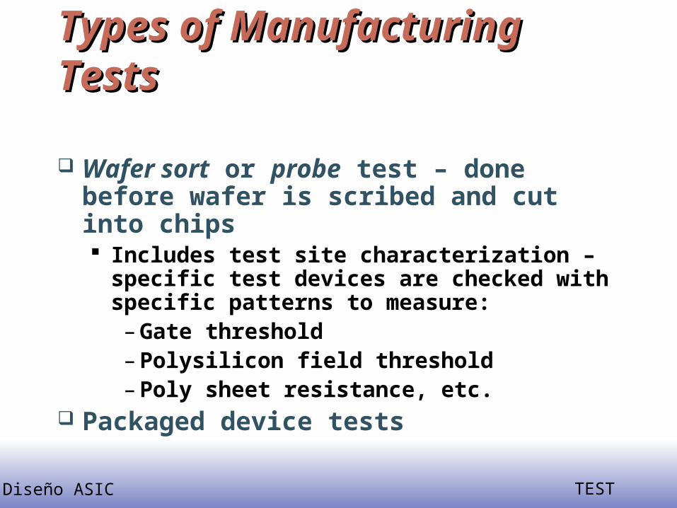
Types of Manufacturing TestsTypes of Manufacturing Tests
Wafer sort or probe test – done before wafer is scribed and cut into chips Includes test site characterization – specific
test devices are checked with specific patterns to measure:
– Gate threshold– Polysilicon field threshold– Poly sheet resistance, etc.
Packaged device tests
Diseño ASIC TEST
Sub-types of TestsSub-types of Tests
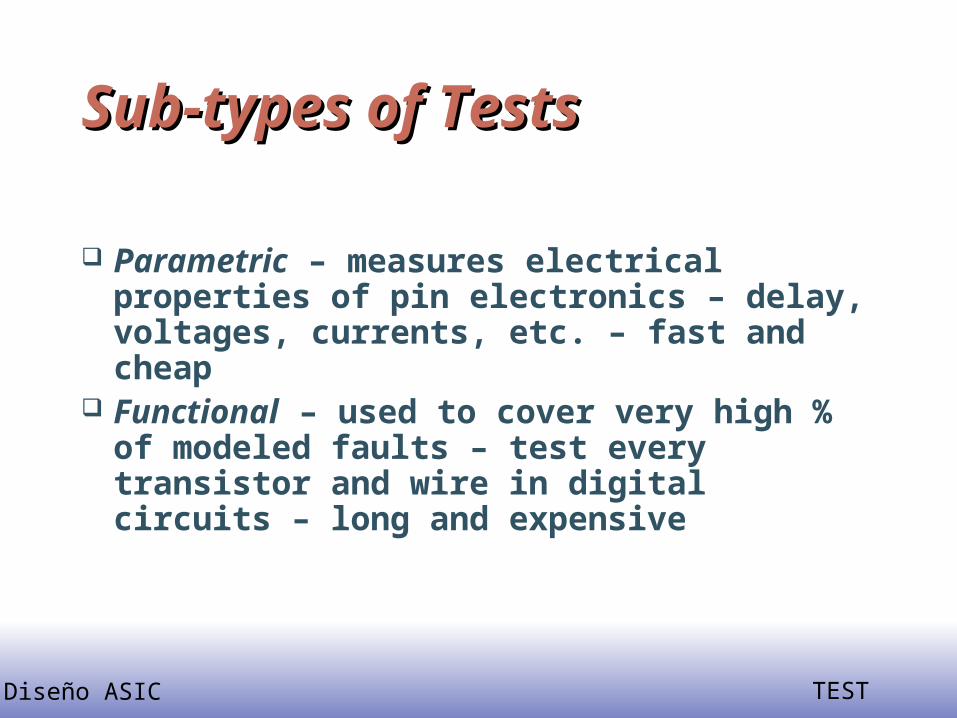
Parametric – measures electrical properties of pin electronics – delay, voltages, currents, etc. – fast and cheap
Functional – used to cover very high % of modeled faults – test every transistor and wire in digital circuits – long and expensive
Diseño ASIC TEST
Two Different Meanings of Two Different Meanings of Functional TestFunctional Test
ATE and Manufacturing World – any vectors applied to cover high % of faults during manufacturing test
Automatic Test-Pattern Generation World – testing with verification vectors, which determine whether hardware matches its specification – typically have low fault coverage (< 70 %)

Diseño ASIC TEST
Test ProgrammingTest Programming

Diseño ASIC TEST
Automatic Test Equipment (ATE)Automatic Test Equipment (ATE)Automatic Test Equipment (ATE)Automatic Test Equipment (ATE)

Diseño ASIC TEST
T6682 ATE SpecificationsT6682 ATE Specifications Uses 0.35 m VLSI chips in implementation 1024 pin channels Speed: 250, 500, or 1000 MHz Timing accuracy: +/- 200 ps Drive voltage: -2.5 to 6 V Clock/strobe accuracy: +/- 870 ps Clock settling resolution: 31.25 ps Pattern multiplexing: write 2 patterns in one ATE
cycle Pin multiplexing: use 2 pins to control 1 DUT pin

Diseño ASIC TEST
Pattern GenerationPattern Generation Sequential pattern generator (SQPG): stores 16
Mvectors of patterns to apply to DUT, vector width determined by # DUT pins
Algorithmic pattern generator (ALPG): 32 independent address bits, 36 data bits For memory test – has address descrambler Has address failure memory
Scan pattern generator (SCPG) supports JTAG boundary scan, greatly reduces test vector memory for full-scan testing 2 Gvector or 8 Gvector sizes

Diseño ASIC TEST
Fault ModelingFault Modeling
Why model faults? Some real defects in VLSI and PCB Common fault models Stuck-at faults
– Single stuck-at faults– Fault equivalence– Fault dominance and checkpoint theorem– Classes of stuck-at faults and multiple faults
Transistor faults
Diseño ASIC TEST
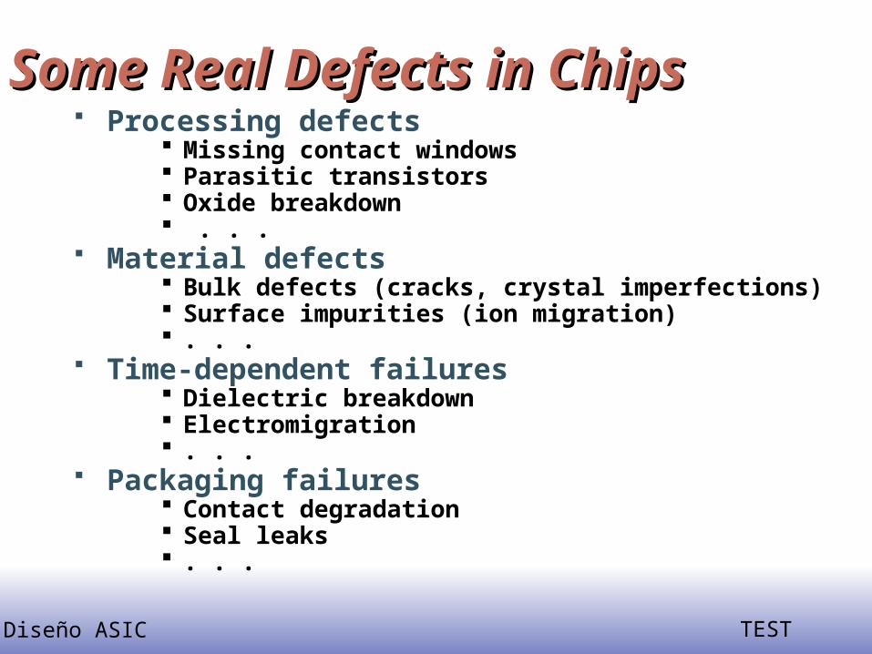
Some Real Defects in ChipsSome Real Defects in Chips Processing defects
Missing contact windows Parasitic transistors Oxide breakdown . . .
Material defects Bulk defects (cracks, crystal imperfections) Surface impurities (ion migration) . . .
Time-dependent failures Dielectric breakdown Electromigration . . .
Packaging failures Contact degradation Seal leaks . . .

Diseño ASIC TEST
Common Fault ModelsCommon Fault Models
Single stuck-at faults Transistor open and short faults Memory faults PLA faults (stuck-at, cross-point, bridging) Functional faults (processors) Delay faults (transition, path) Analog faults
Diseño ASIC TEST
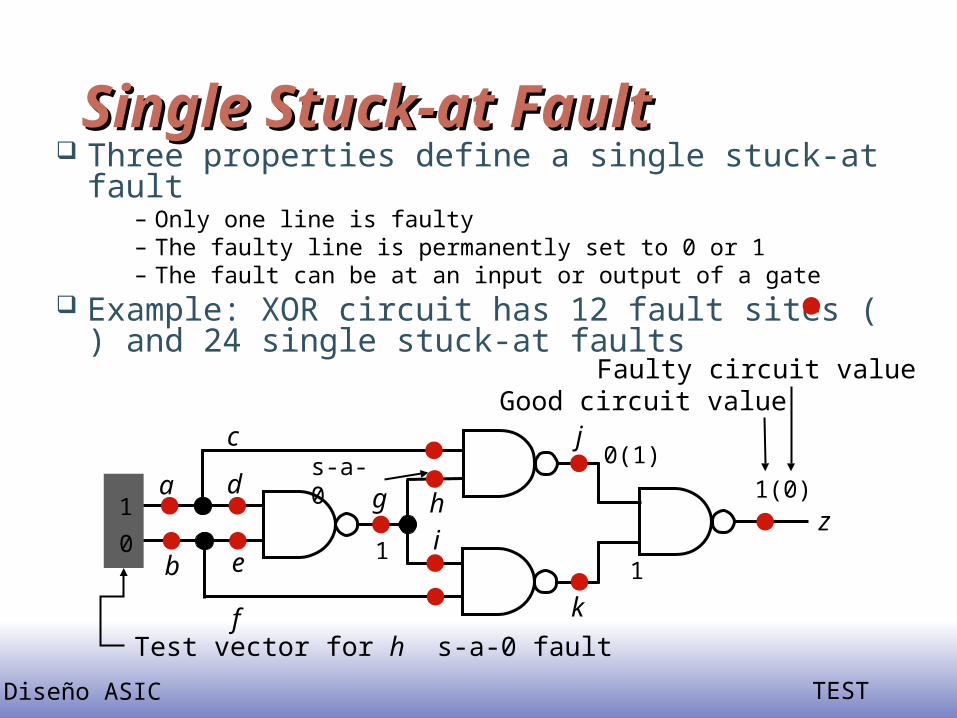
Single Stuck-at FaultSingle Stuck-at Fault Three properties define a single stuck-at fault
– Only one line is faulty– The faulty line is permanently set to 0 or 1– The fault can be at an input or output of a gate
Example: XOR circuit has 12 fault sites ( ) and 24 single stuck-at faults
a
b
c
d
e
f
1
0
g h i 1
s-a-0j
k
z
0(1)1(0)
1
Test vector for h s-a-0 fault
Good circuit valueFaulty circuit value
Diseño ASIC TEST
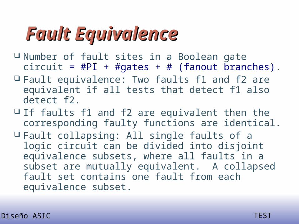
Fault EquivalenceFault Equivalence Number of fault sites in a Boolean gate circuit =
#PI + #gates + # (fanout branches). Fault equivalence: Two faults f1 and f2 are
equivalent if all tests that detect f1 also detect f2. If faults f1 and f2 are equivalent then the
corresponding faulty functions are identical. Fault collapsing: All single faults of a logic circuit
can be divided into disjoint equivalence subsets, where all faults in a subset are mutually equivalent. A collapsed fault set contains one fault from each equivalence subset.

Diseño ASIC TEST
Equivalence RulesEquivalence Rules
sa0 sa1
sa0 sa1
sa0 sa1
sa0 sa1
sa0 sa1
sa0 sa1
sa0 sa1
sa0 sa1
sa0 sa1
sa0 sa1
sa0 sa1
sa0 sa1
sa0
sa1
sa0
sa1
sa0sa0sa1
sa1
sa0
sa0
sa0sa1
sa1
sa1
AND
NAND
OR
NOR
WIRE
NOT
FANOUT

Diseño ASIC TEST
Equivalence ExampleEquivalence Example
sa0 sa1sa0 sa1
sa0 sa1
sa0 sa1
sa0 sa1
sa0 sa1
sa0 sa1
sa0 sa1
sa0 sa1
sa0 sa1
sa0 sa1
sa0 sa1
sa0 sa1
sa0 sa1
sa0 sa1
sa0 sa1
Faults in redremoved byequivalencecollapsing
20Collapse ratio = ----- = 0.625 32

Diseño ASIC TEST
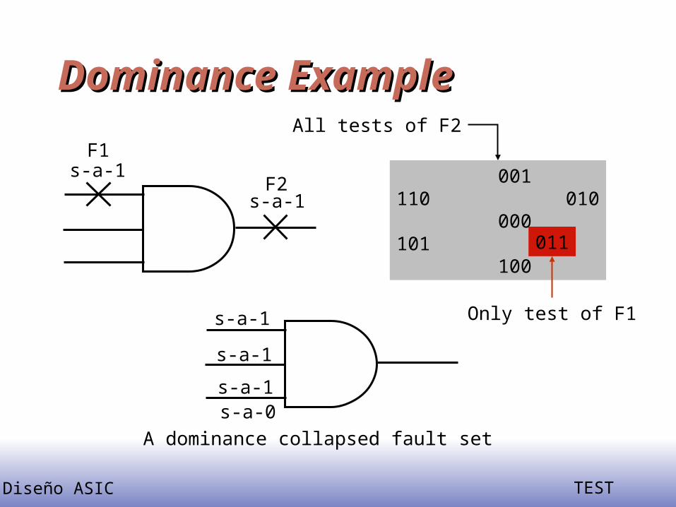
Fault DominanceFault Dominance If all tests of some fault F1 detect another fault F2,
then F2 is said to dominate F1. Dominance fault collapsing: If fault F2 dominates
F1, then F2 is removed from the fault list. When dominance fault collapsing is used, it is
sufficient to consider only the input faults of Boolean gates. See the next example.
In a tree circuit (without fanouts) PI faults form a dominance collapsed fault set.
If two faults dominate each other then they are equivalent.
Diseño ASIC TEST
Dominance ExampleDominance Example
s-a-1F1
s-a-1F2 001
110 010 000101 100
011
All tests of F2
Only test of F1s-a-1
s-a-1
s-a-1s-a-0
A dominance collapsed fault set
Diseño ASIC TEST
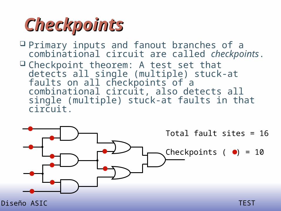
CheckpointsCheckpoints Primary inputs and fanout branches of a
combinational circuit are called checkpoints. Checkpoint theorem: A test set that detects all
single (multiple) stuck-at faults on all checkpoints of a combinational circuit, also detects all single (multiple) stuck-at faults in that circuit.
Total fault sites = 16
Checkpoints ( ) = 10

Diseño ASIC TEST
Classes of Stuck-at FaultsClasses of Stuck-at Faults Following classes of single stuck-at faults
are identified by fault simulators:– Potentially-detectable fault -- Test produces an
unknown (X) state at primary output (PO); detection is probabilistic, usually with 50% probability.
– Initialization fault -- Fault prevents initialization of the faulty circuit; can be detected as a potentially-detectable fault.
– Hyperactive fault -- Fault induces much internal signal activity without reaching PO.
– Redundant fault -- No test exists for the fault.– Untestable fault -- Test generator is unable to find a
test.

Diseño ASIC TEST
Multiple Stuck-at FaultsMultiple Stuck-at Faults A multiple stuck-at fault means that any set of
lines is stuck-at some combination of (0,1) values.
The total number of single and multiple stuck-at faults in a circuit with k single fault sites is 3k-1.
A single fault test can fail to detect the target fault if another fault is also present, however, such masking of one fault by another is rare.
Statistically, single fault tests cover a very large number of multiple faults.

Diseño ASIC TEST
Transistor (Switch) FaultsTransistor (Switch) Faults MOS transistor is considered an ideal switch
and two types of faults are modeled:– Stuck-open -- a single transistor is permanently stuck in the
open state.– Stuck-short -- a single transistor is permanently shorted
irrespective of its gate voltage.
Detection of a stuck-open fault requires two vectors.
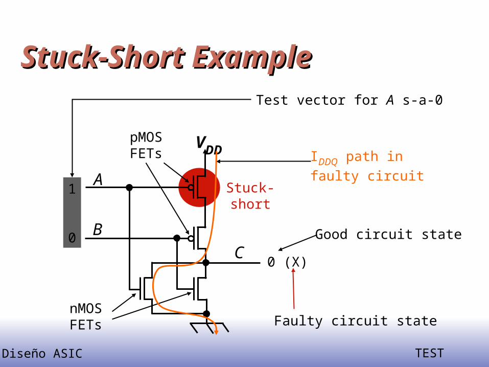
Detection of a stuck-short fault requires the measurement of quiescent current (IDDQ).

Diseño ASIC TEST
Stuck-Open ExampleStuck-Open Example
Two-vector s-op testcan be constructed byordering two s-at testsA
B
VDD
C
pMOSFETs
nMOSFETs
Stuck-open
1
0
0
0
0 1(Z)
Good circuit states
Faulty circuit states
Vector 1: test for A s-a-0(Initialization vector)
Vector 2 (test for A s-a-1)
Diseño ASIC TEST
Stuck-Short ExampleStuck-Short Example
A
B
VDD
C
pMOSFETs
nMOSFETs
Stuck-short
1
0
0 (X)
Good circuit state
Faulty circuit state
Test vector for A s-a-0
IDDQ path infaulty circuit

Diseño ASIC TEST
Problem with stuck-at model: Problem with stuck-at model: CMOS short faultCMOS short fault
‘0’
‘0’
‘0’
‘1’
C
A B
D
A
B
C
D
Causes short circuit betweenVdd and GND for A=C=0, B=1
Possible approach:Supply Current Measurement (IDDQ)but: not applicable for gigascale integration
[Adapted from http://infopad.eecs.berkeley.edu/~icdesign/. Copyright 1996 UCB]

Diseño ASIC TEST
Fault SimulationFault Simulation
Problem and motivation Fault simulation algorithms
– Serial– Parallel– Deductive– Concurrent
Random Fault Sampling

Diseño ASIC TEST
Problem and MotivationProblem and Motivation Fault simulation Problem: Given
A circuit A sequence of test vectors A fault model
Determine Fault coverage - fraction (or percentage) of modeled faults
detected by test vectors Set of undetected faults
Motivation Determine test quality and in turn product quality Find undetected fault targets to improve tests

Diseño ASIC TEST
Fault simulator in a VLSI Design Fault simulator in a VLSI Design ProcessProcess
Verified designnetlist
Verificationinput stimuli
Fault simulator Test vectors
Modeledfault list
Testgenerator
Testcompactor
Faultcoverage
?
Remove tested faults
Deletevectors
Add vectors
Low
Adequate
Stop

Diseño ASIC TEST
Fault Simulation ScenarioFault Simulation Scenario Circuit model: mixed-level
– Mostly logic with some switch-level for high-impedance (Z) and bidirectional signals
– High-level models (memory, etc.) with pin faults
Signal states: logic– Two (0, 1) or three (0, 1, X) states for purely Boolean logic
circuits– Four states (0, 1, X, Z) for sequential MOS circuits
Timing:– Zero-delay for combinational and synchronous circuits– Mostly unit-delay for circuits with feedback
Diseño ASIC TEST
Fault Simulation Scenario Fault Simulation Scenario (continued)(continued)
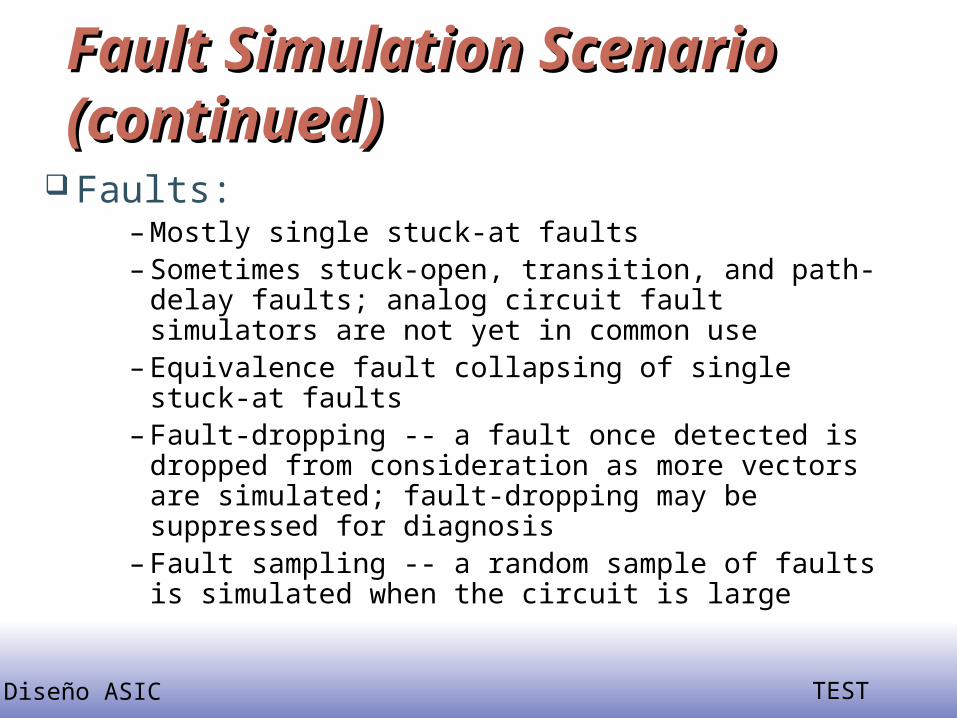
Faults:– Mostly single stuck-at faults– Sometimes stuck-open, transition, and path-delay
faults; analog circuit fault simulators are not yet in common use
– Equivalence fault collapsing of single stuck-at faults– Fault-dropping -- a fault once detected is dropped
from consideration as more vectors are simulated; fault-dropping may be suppressed for diagnosis
– Fault sampling -- a random sample of faults is simulated when the circuit is large

Diseño ASIC TEST
Fault Simulation AlgorithmsFault Simulation Algorithms
Serial Parallel Deductive Concurrent Differential

Diseño ASIC TEST
Serial AlgorithmSerial Algorithm Algorithm: Simulate fault-free circuit and save
responses. Repeat following steps for each fault in the fault list:
– Modify netlist by injecting one fault– Simulate modified netlist, vector by vector, comparing
responses with saved responses– If response differs, report fault detection and suspend
simulation of remaining vectors
Advantages:– Easy to implement; needs only a true-value simulator, less
memory– Most faults, including analog faults, can be simulated

Diseño ASIC TEST
Serial Algorithm (Cont.)Serial Algorithm (Cont.) Disadvantage: Much repeated computation; CPU time
prohibitive for VLSI circuits Alternative: Simulate many faults together
Test vectors Fault-free circuit
Circuit with fault f1
Circuit with fault f2
Circuit with fault fn
Comparator f1 detected?
Comparator f2 detected?
Comparator fn detected?

Diseño ASIC TEST
Parallel Fault SimulationParallel Fault Simulation Compiled-code method; best with two-states
(0,1) Exploits inherent bit-parallelism of logic
operations on computer words Storage: one word per line for two-state
simulation Multi-pass simulation: Each pass simulates w-
1 new faults, where w is the machine word length
Speed up over serial method ~ w-1 Not suitable for circuits with timing-critical and
non-Boolean logic

Diseño ASIC TEST
Parallel Fault Sim. ExampleParallel Fault Sim. Example
a
b c
d
e
f
g
1 1 1
1 1 1 1 0 1
1 0 1
0 0 0
1 0 1
s-a-1
s-a-0
0 0 1
c s-a-0 detected
Bit 0: fault-free circuit
Bit 1: circuit with c s-a-0
Bit 2: circuit with f s-a-1

Diseño ASIC TEST
Deductive Fault SimulationDeductive Fault Simulation One-pass simulation Each line k contains a list Lk of faults
detectable on k Following true-value simulation of each
vector, fault lists of all gate output lines are updated using set-theoretic rules, signal values, and gate input fault lists
PO fault lists provide detection data Limitations:
– Set-theoretic rules difficult to derive for non-Boolean gates
– Gate delays are difficult to use

Diseño ASIC TEST
Deductive Fault Sim. ExampleDeductive Fault Sim. Example
a
b c
d
e
f
g
1
1 1
0
1
{a0}
{b0 , c0}
{b0}
{b0 , d0}
Le = La U Lc U {e0}
= {a0 , b0 , c0 , e0}
Lg = (Le Lf ) U {g0}
= {a0 , c0 , e0 , g0}
U
{b0 , d0 , f1}
Notation: Lk is fault list for line k
kn is s-a-n fault on line k
Faults detected bythe input vector

Diseño ASIC TEST
Concurrent Fault SimulationConcurrent Fault Simulation Event-driven simulation of fault-free circuit and only
those parts of the faulty circuit that differ in signal states from the fault-free circuit.
A list per gate containing copies of the gate from all faulty circuits in which this gate differs. List element contains fault ID, gate input and output values and internal states, if any.
All events of fault-free and all faulty circuits are implicitly simulated.
Faults can be simulated in any modeling style or detail supported in true-value simulation (offers most flexibility.)
Faster than other methods, but uses most memory.

Diseño ASIC TEST
Conc. Fault Sim. ExampleConc. Fault Sim. Example
a
b c
d
e
f
g
1
11
0
1
1
11
1
01
1 0
0
10
1
00
1
00
1
10
1
00
1
11
1
11
0
00
0
11
0
00
0
00
0 1 0 1 1 1
a0 b0 c0 e0
a0 b0
b0
c0 e0
d0d0 g0 f1
f1
Diseño ASIC TEST
Fault SamplingFault Sampling
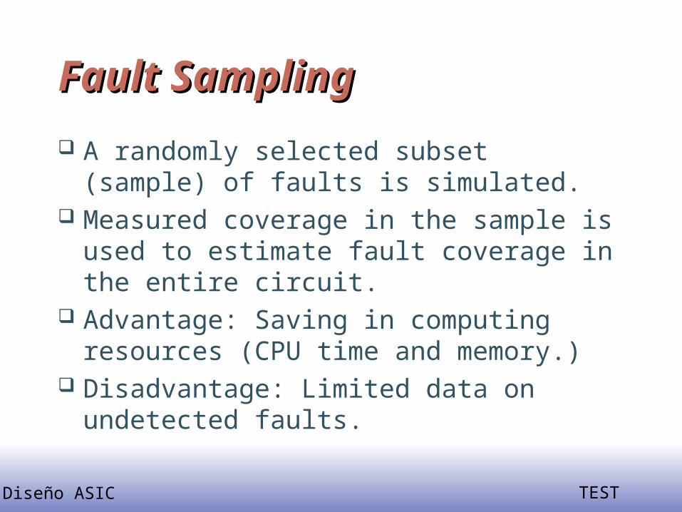
A randomly selected subset (sample) of faults is simulated.
Measured coverage in the sample is used to estimate fault coverage in the entire circuit.
Advantage: Saving in computing resources (CPU time and memory.)
Disadvantage: Limited data on undetected faults.

Diseño ASIC TEST
Motivation for SamplingMotivation for Sampling Complexity of fault simulation depends on:
– Number of gates– Number of faults– Number of vectors
Complexity of fault simulation with fault sampling depends on:
– Number of gates– Number of vectors
Diseño ASIC TEST
Random Sampling ModelRandom Sampling Model
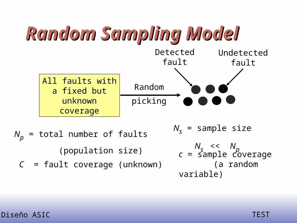
All faults witha fixed butunknowncoverage
Detectedfault
Undetectedfault
Random
picking
Np = total number of faults
(population size)
C = fault coverage (unknown)
Ns = sample size
Ns << Npc = sample coverage (a random variable)

Diseño ASIC TEST
Functional vs. Structural ATPGFunctional vs. Structural ATPG
Automatic Test-Pattern Generation Automatic Test-Pattern Generation (ATPG) Basics(ATPG) Basics
Diseño ASIC TEST
Carry CircuitCarry Circuit
Diseño ASIC TEST
Functional vs. StructuralFunctional vs. Structural(Continued)(Continued)
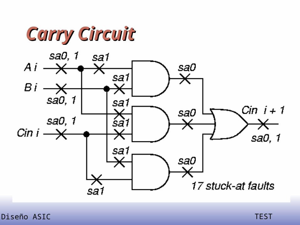
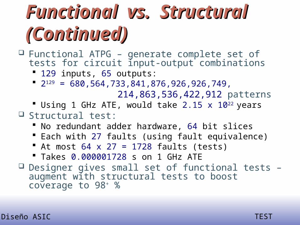
Functional ATPG – generate complete set of tests for circuit input-output combinations 129 inputs, 65 outputs: 2129 = 680,564,733,841,876,926,926,749,
214,863,536,422,912 patterns Using 1 GHz ATE, would take 2.15 x 10²² years
Structural test: No redundant adder hardware, 64 bit slices Each with 27 faults (using fault equivalence) At most 64 x 27 = 1728 faults (tests) Takes 0.000001728 s on 1 GHz ATE
Designer gives small set of functional tests – augment with structural tests to boost coverage to 98+ %

Diseño ASIC TEST
Automatic Test Pattern Automatic Test Pattern Generation: Path SensitizationGeneration: Path Sensitization
Out
Techniques Used: D-algorithm, Podem
Goals: Determine input pattern that makes a faultcontrollable (triggers the fault, and makes its impactvisible at the output nodes)
sa011
0
11
10
1
Fault propagation
Fault enabling
Diseño ASIC TEST
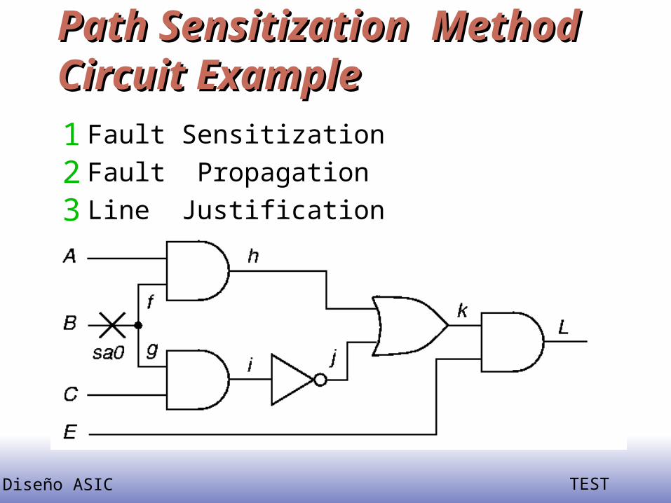
Path Sensitization Method Circuit Path Sensitization Method Circuit ExampleExample1 Fault Sensitization
2 Fault Propagation
3 Line Justification

Diseño ASIC TEST
Using 5-Valued LogicUsing 5-Valued Logic
SymbolDD01X
Meaning0/11/00/01/1X/X
FailingMachine
1001X
GoodMachine
0101X
Represent two machines, which are simulated simultaneously: Good circuit machine (1st value) Bad circuit machine (2nd value)
Diseño ASIC TEST
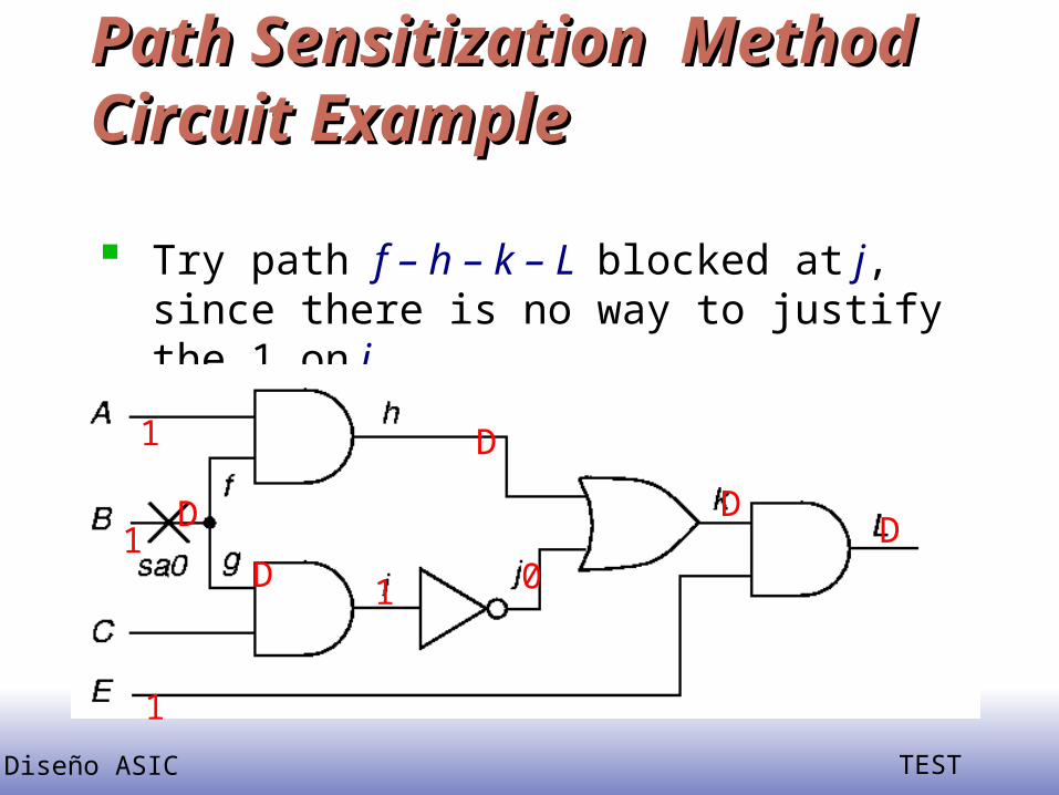
Path Sensitization Method Circuit Path Sensitization Method Circuit ExampleExample
Try path f – h – k – L blocked at j, since there is no way to justify the 1 on i
10
D
D1
1
1DD
D

Diseño ASIC TEST
Path Sensitization Method Circuit Path Sensitization Method Circuit ExampleExample
Try simultaneous paths f – h – k – L and
g – i – j – k – L blocked at k because D-
frontier (chain of D or D) disappears
1
DD D
DD
1
1

Diseño ASIC TEST
Path Sensitization Method Circuit Path Sensitization Method Circuit ExampleExample
Final try: path g – i – j – k – L – test found!
0
D D D
1 DD
1
0
1

Diseño ASIC TEST
Irredundant Hardware and Test Irredundant Hardware and Test PatternsPatterns
Combinational ATPG can find redundant (unnecessary) hardware
Fault Test
a sa1, b sa0 A = 1
a sa0, b sa1 A = 0 Therefore, these faults are not redundant

Diseño ASIC TEST
Redundant Hardware and Redundant Hardware and SimplificationSimplification
Diseño ASIC TEST
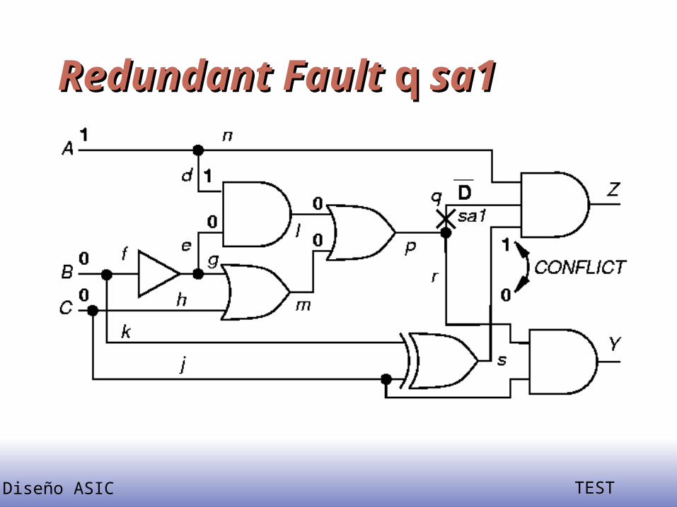
Redundant Fault Redundant Fault qq sa1 sa1
Diseño ASIC TEST
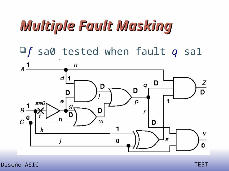
Multiple Fault MaskingMultiple Fault Masking
f sa0 tested when fault q sa1 not there

Diseño ASIC TEST
Multiple Fault MaskingMultiple Fault Masking f sa0 masked when fault q sa1 also
present
Diseño ASIC TEST
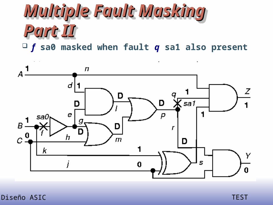
Multiple Fault MaskingMultiple Fault MaskingPart IIPart IIMultiple Fault MaskingMultiple Fault MaskingPart IIPart II f sa0 masked when fault q sa1 also present
Diseño ASIC TEST
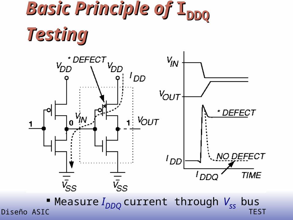
Basic Principle of Basic Principle of IIDDQDDQ Testing Testing
Measure IDDQ current through Vss bus
Diseño ASIC TEST
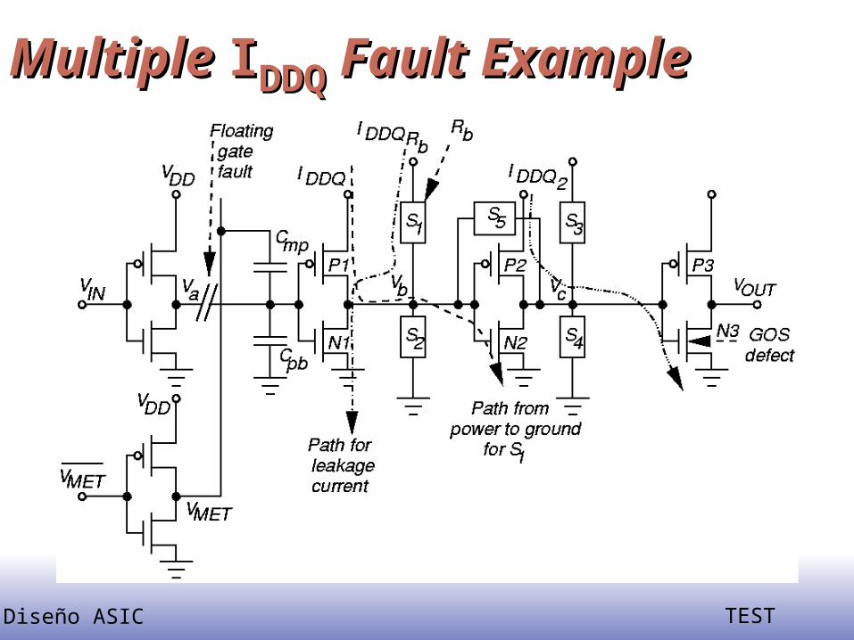
Multiple Multiple IIDDQDDQ Fault Example Fault Example

Diseño ASIC TEST
Limitations of Limitations of IIDDQDDQ Testing Testing
Sub-micron technologies have increased leakage currents Transistor sub-threshold conduction Harder to find IDDQ threshold separating
good & bad chips IDDQ tests work:
When average defect-induced current greater than average good IC current
Small variation in IDDQ over test sequence & between chips