disclaimer elite elite español s i g n a t u r e s i g n a t u r e 1. ... the tank thickness and...
TRANSCRIPT

Disclaimer
ELITEespañol
S I G N A T U R E

�
S I G N A T U R E
1. Productspecificationsandtechnicalcharacteristics.
1.1. Tableoftechnicalcharacteristics
1.2. Packaging
1.3. Generalmeasurements
2. Checklistofqualitycontrolspassed.
3. Certificatesavailablefortheproduct,productionprocessandsystemsimplementedinproduction.
4. Detailedcertificateofguarantee.
5. Characteristicsanddesignstandards.
6. ExplodedView.
7. Recommendationstobeconsidered:
7.1. Packaging
7.2. Storage
7.3. Transportation
7.4. Location
7.5. Startingupprocess
7.6. Installation
7.6.1.Installthefilterinitsfinallocation
7.6.2. Loadingsand
7.6.3.Commissioning
7.7. Filtrationandcleaning
7.7.1. Filtration
7.7.2. Wash
7.7.3. Recirculation
7.7.4. Draining
7.7.5. Rinse
7.8. Maintenanceandsanddrainage
7.8.1. Thewinterperiod
7.8.2. Sanddrainage
8. Maintenanceandsanddrainage.
9. Mostcommonbreakdownsandsafetywarnings.
10.Tableof“DOANDDONOT”.
CONTENTS

�
S I G N A T U R E
ATLASFILTER
Reinforced polyester sand filters.
1.Productspecificationsandtechnicalcharacteristics
MODEL DESCRIPTION
36596 Filter model ATLAS Ø 500 Side
36597 Filter model ATLAS Ø 600 Side
36598 Filter model ATLAS Ø 750 Side
36599 Filter model ATLAS Ø 900 Side
Made with polyester resins and fibre-glass.
Excellent Gel-coat finish in the RAL 8029 colour.
The filter was designed with a high safety factor to guarantee perfect op-eration.
The two filter parts are joined by means of a specially-reinforced seal with fibre-glass and polyester resin.
200 mm plastic cover.
Plastic cap for easier drainage of sand in the filter.
Fixed with �” collectors and a perma-nent plastic diffuser.
•
•
•
•
•
•
•
Interior piping reinforced with PN-�6 tubes.
2 1/2” sand release.
Equipped with pressure gauge, manual water and air drain.
Connections for selector valve with six functions: filter, wash, rinse, re-circula-tion, drainage and closure.
The filter comes with a built-in safety valve to avoid any overpressure.
Maximum working pressure: 2.5 Kg/cm2.
•
•
•
•
•
•
3
S I G N A T U R E
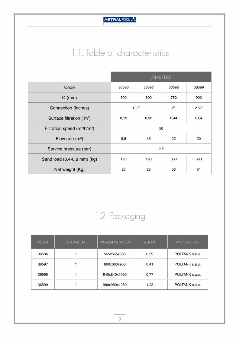
1.1.Tableofcharacteristics
ATLASFILTER
Code 36596 36597 36598 36599
Ø (mm) 500 600 750 900
Connection (inches) � �/�” �” � �/�”
Surface filtration ( m�) 0,�9 0,30 0,44 0,64
Filtration speed (m3/h/m�) 50
Flow rate (m3) 9,5 �5 �� 30
Service pressure (bar) �,5
Sand load (0,4-0,8 mm) (kg) ��0 �90 360 580
Net weight (Kg) �0 �5 33 5�
MODEL STANDARDUNITS MEASUREMENTS(m3) VOLUME MANUFACTURER
36596 � 565x565x895 0,�9 POLTANK s.a.u.
36597 � 660x660x950 0,4� POLTANK s.a.u.
36598 � 840x840x�090 0,77 POLTANK s.a.u.
36599 � 980x980x��80 �,�3 POLTANK s.a.u.
1.2.Packaging
4
S I G N A T U R E
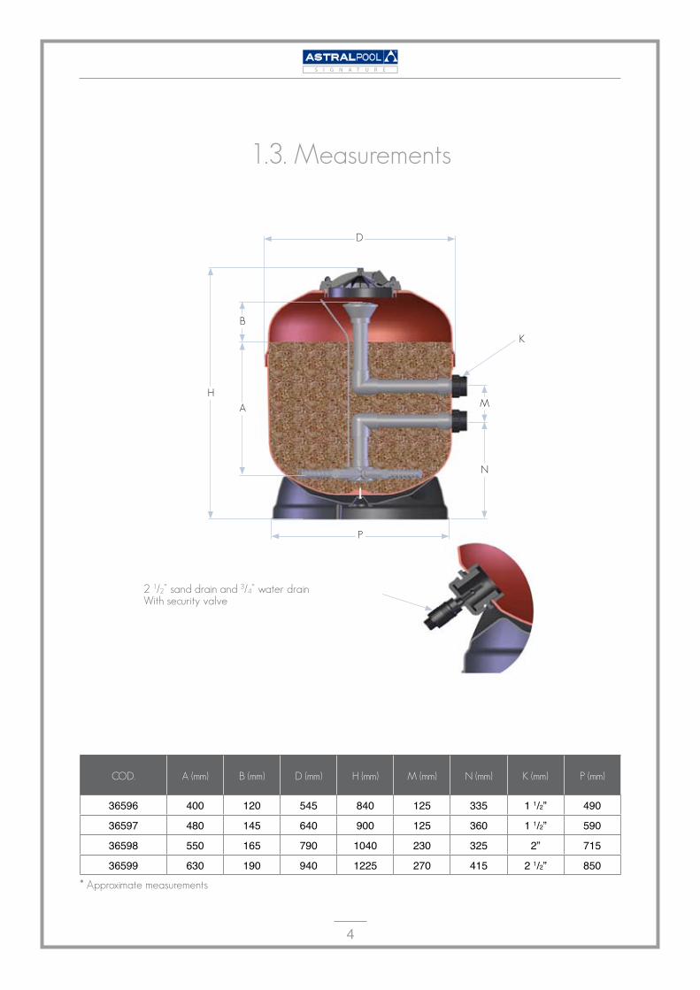
1.3.Measurements
COD. A(mm) B(mm) D(mm) H(mm) M(mm) N(mm) K(mm) P(mm)
36596 400 ��0 545 840 ��5 335 � �/�” 490
36597 480 �45 640 900 ��5 360 � �/�” 590
36598 550 �65 790 �040 �30 3�5 �” 7�5
36599 630 �90 940 ���5 �70 4�5 � �/�” 850
N
D
H
A
B
P
M
K
21/2”sanddrainand3/4”waterdrainWithsecurityvalve
*Approximatemeasurements

5
S I G N A T U R E
2.Checklistofqualitycontrolspassed
MATERIALS INTAKE
Resinqualitycertificates
Uppercovercontrol
Neckframecontrol
Securityvalvecontrol
ENTRY
LAMINATED POLYESTER MANUFACTURING TANK
INTERIOR MECHANISATION +
ASSEMBLY
FINISHED PRODUCT
FINAL
SM:Weightcontrol
QC:Fibreandresinpercentage
QC:Screwtighteningcontrol
QC:Bodyunionconnectiontighteningcontrol
SM+QC:Linearoutlets
SM:Bodythicknessintheneckzone
SM+CQ:Interior-visualassembly
SM+CQ:Watertightnesscontrol
QC+QC:Finishedvisualappearance
SM:100%SELF-MONITORINGINTEGRATEDIN
THEMANUFACTURINGPROCESSITSELF.
QC:PAPERWORKCONTROLSBYTHEQUALITY
DEPARTMENT.
6
S I G N A T U R E
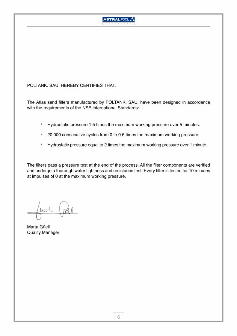
POLTANK. SAU. HEREBY CERTIFIES THAT:
The Atlas sand filters manufactured by POLTANK, SAU, have been designed in accordance with the requirements of the NSF International Standards:
Hydrostatic pressure 1.5 times the maximum working pressure over 5 minutes.
20,000 consecutive cycles from 0 to 0.6 times the maximum working pressure.
Hydrostatic pressure equal to 2 times the maximum working pressure over 1 minute.
The filters pass a pressure test at the end of the process. All the filter components are verified and undergo a thorough water tightness and resistance test: Every filter is tested for 10 minutes at impulses of 0 at the maximum working pressure.
Marta Güell Quality Manager
•
•
•

7
S I G N A T U R E
3.Certificatesavailablefortheproduct,productionprocessandsystemsimplementedinproduction
8
S I G N A T U R E
4.CertificateofGuarantee
GENERALASPECTS
1.1. In accordance with these provisions, the seller guarantees that the product that corre-sponds to this guarantee shows no compliance deficiency at the time of delivery. .
1.2. The Product Guarantee Period is 10 YEARS, and starts from the moment it is delivered to the buyer, understood as AstralPool’s direct customer.
1.3. If the Product were to show a compliance deficiency and the buyer notifies the seller within the Guarantee Period, the Product must be repaired or replaced at the seller’s own cost where considered to be appropriate, unless it is impossible or disproportionate.
1.4. If the Product cannot be repaired or replaced, the buyer will be able to receive a propor-tional reduction in the price or, if the compliance deficiency is sufficiently significant, the sales contract will be terminated.
1.5. The parts that are replaced or repaired in virtue of this guarantee will not result in any exten-sion of the guarantee on the original Product; if appropriate they will have their own guarantee.
1.6. In order for this guarantee to be effective, the buyer must provide proof of the date the Product was purchased and delivered. .
1.7. If more than six months has passed since the Product was delivered to the buyer, and said buyer were to claim a compliance deficiency, the buyer must prove the origin and existence of the alleged defect.
1.8. This Certificate of Guarantee does not restrict or infringe on the consumers’ rights in ac-cordance with national standards as dictated by law.
SPECIALCONDITIONS
2.1. In order for this guarantee to be valid, the buyer must strictly follow the Manufacturer’s instruc-tions included in the documentation that accompanies the Product, as applicable according to the Product line and model.
2.2. When a schedule is specified for the replacement, maintenance or cleaning of certain Prod-uct pieces or components, the guarantee will only be valid if the schedule has been correctly followed.
2.3. The Product is covered by a full guarantee for the first 5 years, and covers any kind of de-fect of the filter body for the following 5 years, all of the rest of components are excluded: upper cover, base, body union outlet, sand and internal drain.
2.4. The filter is specifically excluded from any guarantee extension.

9
S I G N A T U R E
2.5. If the product is to be replaced, all freight charges and expenditures to and from the factory, to move or reinstall the product or installation of the replacement, are the responsibility of the buyer.
2.6. If the Product is to be repaired, the expenditures derived from the repair work and transpor-tation shall be the responsibility of the buyer.
2.7. The manufacturer is not liable for damages and expenditures for any halt in activity, which includes time and materials derived from the replacement or substitution of the products.
2.8. The manufacturer does not authorise other people to extend any guarantee regarding their articles nor shall it be subject to any unauthorised guarantee made in connection with the seller of their products.
LIMITATIONS
3.1. This guarantee will only be applicable in those sales made to consumers, with “consumers” understood as people who acquire the Product without the intention of using it in the scope of their professional activity.
3.2. The guarantee does not cover any normal wear and tear caused by the use of product. All pieces, components and/or expendable or consumable materials such as sand etc., shall be covered as per the documentation accompanying the Product, where appropriate..
3.3. The guarantee does not cover the following cases in which the Product: (i) has been sub-ject to incorrect treatment; (ii) has been inspected, repaired, maintained or handled by an unau-thorised person; (iii) has been repaired or maintained with pieces that are not original or (iv) has been installed or tuned on in an improper way.
3.4. When the Product compliance deficiency is a result of improper installation or commis-sioning, this guarantee will only be applicable if this installation or commissioning is included in the sales agreement contract of the Product and it has been carried out by the seller, or under his/her responsibility.
3.5. Damages or malfunctions resulting from exposures to temperatures below 0ºC (32º F) or above 50ºC (125º F).
3.6. Damages or malfunctions caused by water hammer or as a consequence of using an over-sized pump in the filtration system.
3.7. The product comes with a built-in safety valve to avoid overpressure; the guarantee shall no longer be valid if this valve has been removed.
3.8. The product has been designed to work in swimming pool water, meaning that the water will have to comply with the indicated chemical product concentrations:
pH 6,8-8Freeresidualchlorine 0,4-1,5mg/lBromine 1-3mg/lItisalsoappropriateforuseinsaltwaterpoolswithamaximumsaltconcentrationof4%.ThefilterISNOTSUITABLEforworkingwithozone.
�0
S I G N A T U R E
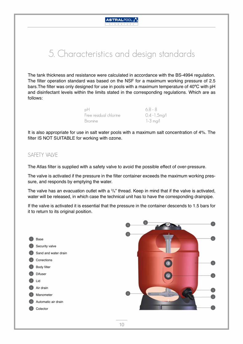
5.Characteristicsanddesignstandards
The tank thickness and resistance were calculated in accordance with the BS-4994 regulation.The filter operation standard was based on the NSF for a maximum working pressure of 2.5 bars.The filter was only designed for use in pools with a maximum temperature of 40ºC with pH and disinfectant levels within the limits stated in the corresponding regulations. Which are as follows:
pH 6,8-8Freeresidualchlorine 0,4-1,5mg/lBromine 1-3mg/l
It is also appropriate for use in salt water pools with a maximum salt concentration of 4%. The filter IS NOT SUITABLE for working with ozone.
SAFETYVALVE
The Atlas filter is supplied with a safety valve to avoid the possible effect of over-pressure.
The valve is activated if the pressure in the filter container exceeds the maximum working pres-sure, and responds by emptying the water.
The valve has an evacuation outlet with a 3/4” thread. Keep in mind that if the valve is activated, water will be released, in which case the technical unit has to have the corresponding drainpipe.
If the valve is activated it is essential that the pressure in the container descends to 1.5 bars for it to return to its original position.
89
10
11
7
6
5
4
2
1
3
1 Base
2 Security valve
3 Sand and water drain
4 Conections
5 Body filter
6 Difuser
7 Lid
8 Air drain
9 Manometer
10 Automatic air drain
11 Colector
��
S I G N A T U R E
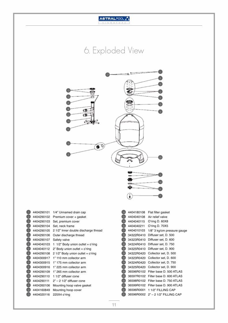
1 4404�90�0� �/4” Unnamed drain cap 2 4404�90�0� Premium cover + gasket3 4404�90�03 Set, premium cover 4 4404�90�04 Set, neck frame5 4404�90�05 2 1/2” Inner double discharge thread6 4404�90�06 Outer discharge thread 7 4404�90�07 Safety valve8 4404040�03 1 1/2” Body union outlet + o’ring8 4404040��� 2” Body union outlet + o’ring8 4404�90�08 2 1/2” Body union outlet + o’ring9 44043009�7 �” ��0 mm collector arm9 44043009�5 �” �75 mm collector arm9 44043009�6 �” ��5 mm collector arm9 4404�90�09 �” �65 mm collector arm10 4404�90��0 � �/�” diffuser cone10 4404�90��� �” – � �/�” diffuser cone11 4404�60�06 Mounting hoop valve gasket12 4404�60849 Mounting hoop cover13 44040�0��6 225X4 o’ring
6.ExplodedView
1
2
3
4
5
6
7
8
9
10
11
12
13
14
15
16
17
18
19
20
21
22
14 4404�80�08 Flat filter gasket15 4404040�08 Air relief valve16 4404040��5 O’ring D. 60X816 4404040��� O’ring D. 70X517 44040�0�03 �/8” 3 kg/cm pressure gauge18 343��R04�0 Diffuser set, D. 500 18 343�3R04�0 Diffuser set, D. 600 18 343�4R04�0 Diffuser set, D. 750 18 343�5R04�0 Diffuser set, D. 90019 343��R04�0 Collector set, D. 50019 343�3R04�0 Collector set, D. 60019 343�4R04�0 Collector set, D. 75019 343�5R04�0 Collector set, D. 90020 36596R0�0� Filter base D. 500 ATLAS20 36597R0�0� Filter base D. 600 ATLAS20 36598R0�0� Filter base D. 750 ATLAS20 36599R0�0� Filter base D. 900 ATLAS21 36596R000� � �/�” FILLING CAP21 36596R000� �” – � �/�” FILLING CAP

��
S I G N A T U R E
7.Recommendations
7.1.PACKAGING:
The ATLAS filter is delivered adequately packed in a sealed cardboard box on which positioning and stacking logistic information for palleting is indicated.Any failure to comply with this information can result in damage to the product.
Due to the dimensions and weight, the 900 diameter filter is supplied on its own pallet so that it can be handled with a forklift truck or pallet jack.The components that should be found in the packaging are indicated in the instructions manual.
7.2.STORAGE:
The filter can be stored in any kind of warehouse protected from harsh weather conditions. UV rays or direct contact with water could deteriorate the packaging.
Maximum storage temperature: 50 ºCMinimum storage temperature: -5ºC
7.3.TRANSPORT:
The filter boxes should be transported on adequately secured pallets.Once at the installation, transport the filter to its final location inside the packaging. If for any reason this is not possible, the filter should be handled with maximum care.
Any friction, bumps or contact with rough surfaces can cause damage to the exterior finish.
7.4.LOCATION:
The filter must be installed as close to the pool as possible, preferably within 50 metres of the surface of the pool. Be sure there is a drainpipe in the spot where the filter will be located. This drainpipe must be adequately sized to the installation flow.
Be sure the surface area where the filter is installed is horizontal, stable, resistant to the weight of the filter, as indicated in the table of characteristics, and is completely clean.
There must be enough space in the area around the filter so that the required inspections and maintenance throughout the life of the pool can be carried out.

�3
S I G N A T U R E
7.5.STARTINGUPPROCESS
The water is drawn in from the bottom of the pool through the drain 1 and from the surface using the skimmers 2 , and is carried through the pump 4 to the filter 5 by separate conduction pas-sages fitted to their corresponding valves 3 and returned to the pool through distributors ( 6 , jet propulsion nozzles). The nozzles are installed on the side opposite the drain and skimmers, thus completing renewing the pool water.
The actual filter is composed of the silicon sand load through which the water is circulated in a descending motion, thereby retaining the material suspended in the pool to be filtered.Once the filtration cycle begins, the filter will have to be cleaned after a certain time, since the sand will have become blocked with dirt, thus preventing the passage of water.
When the filter pressure has reached a level above 1.3 Kg/cm3, it is time for a cleaning cycle.The backwash reverses the circulation motion of the water in the filter and in doing so expels the filtered materials out to the drainpipe.
Keeping this important information in mind, the operating instructions found below should not be difficult to follow.
topool
todrainpipefrompool
1
2
34
5
6
Selectorvalve

�4
S I G N A T U R E
7.6.INSTALLATION:
7.6.1.INSTALLTHEFILTERINITSFINALLOCATION
Install the selector valve in the filter, ensuring that the gaskets between the valve and the filter are correctly positioned.
Make the three connections needed for the selector valve: pump tubing to the valve, from the valve to the drainpipe and from the valve to the side of the pool. Each of the three outputs are identified on the valve.
IMPORTANT: Do not use for the iron and hemp selector valve tubing connection. Plastic acces-sories and Teflon tape must be used. These terminal connections bolted at 11/2” and 2” and rub-ber gaskets, are available from your distributor.
Assemble the pressure gauge and the air releasing cap (see exploded view). Install the safety valve. Connect the valve to the thread from the sand drain by hand.
PRESSUREGAUGEASSEMBLY SAFETYVALVEASSEMBLY
topool
todrainpipefrompool
selectorvalve
�5
S I G N A T U R E
7.6.2.LOADINGSAND
To get maximum performance out of this filter, it must be filled with silica sand with a particle size from 0.4 to 0.8 mm. With the quantity indicated in the table of characteristics, proceed as follows:
Carry out the loading once the filter is placed in its location and the joining tubing is installed.
Loosen the nuts on the cover and remove the cover and O-ring seal.
To prevent sand from escaping into the internal components, dismantle the upper diffuser cap and replace it with the cover supplied in the packaging.
Fill the filter with water up to the half way point.
Pour the necessary quantity of sand into the filter. See table of characteristics or technical characteristic at the beginning of the document.
Clean the area around the cover seal.
Repeat the previous operation in the opposite order, remove the diffuser tubing filling cap and put the diffuser cover back on.
Position and hold the filter cover in place. It is very important that the surface area around the O ring seal is completely free from sand. Place the O ring seal in its location, position the upper cover and fix the corresponding nuts in place.
The nuts must be tightened cross-wise a couple of times to approximately 2-3 Nm. Once ev-erything is tightened, check it a second time to ensure all the nuts are correctly tightened.
7.6.3.COMMISSIONING
Once the filter is filled with sand it is necessary to carry out a wash cycle. Proceed in the follow-ing way:
Fill the filter and the installation tubing with water, removing all the air that might be there using the air drain in the upper cover of the filter.
Place the selector valve in the “WASH” position.
Open the valves that control the pool vacuum tubing and connect the pump. Throughout this process the water from the pool enters the filter through the collector arms, comes out through the diffuser and is sent to the drainpipe. In order to throw out the least amount of water, look through the valve viewfinder to see when the water becomes transparent and is no longer cloudy.
Stop the pump, place the valve in the “RINSE” position and rinse for about 30 seconds. In this phase, the water enters via the diffuser, leaves through the collector and is sent to the drainpipe. The purpose of this phase is to finish removing any particles in suspension and stabilise the sand to ensure that in the next filtration phase, the water is returned the pool in perfect condition.
1.
2.
3.
4.
5.
6.
7.
8.
1.
2.
3.
4.
�6
S I G N A T U R E
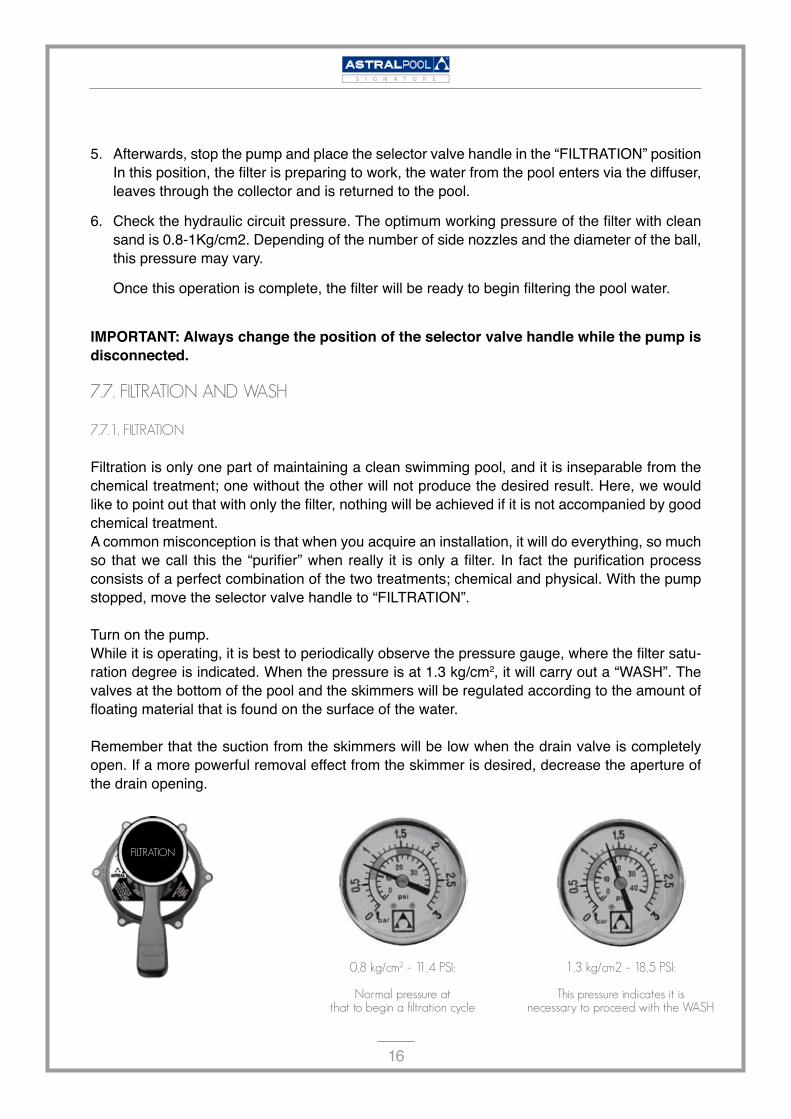
Afterwards, stop the pump and place the selector valve handle in the “FILTRATION” position In this position, the filter is preparing to work, the water from the pool enters via the diffuser, leaves through the collector and is returned to the pool.
Check the hydraulic circuit pressure. The optimum working pressure of the filter with clean sand is 0.8-1Kg/cm2. Depending of the number of side nozzles and the diameter of the ball, this pressure may vary.
Once this operation is complete, the filter will be ready to begin filtering the pool water.
IMPORTANT: Always change the position of the selector valve handle while the pump is disconnected.
7.7.FILTRATIONANDWASH
7.7.1.FILTRATION
Filtration is only one part of maintaining a clean swimming pool, and it is inseparable from the chemical treatment; one without the other will not produce the desired result. Here, we would like to point out that with only the filter, nothing will be achieved if it is not accompanied by good chemical treatment.A common misconception is that when you acquire an installation, it will do everything, so much so that we call this the “purifier” when really it is only a filter. In fact the purification process consists of a perfect combination of the two treatments; chemical and physical. With the pump stopped, move the selector valve handle to “FILTRATION”.
Turn on the pump.While it is operating, it is best to periodically observe the pressure gauge, where the filter satu-ration degree is indicated. When the pressure is at 1.3 kg/cm�, it will carry out a “WASH”. The valves at the bottom of the pool and the skimmers will be regulated according to the amount of floating material that is found on the surface of the water.
Remember that the suction from the skimmers will be low when the drain valve is completely open. If a more powerful removal effect from the skimmer is desired, decrease the aperture of the drain opening.
5.
6.
0,8kg/cm2–11,4PSI:
Normalpressureatthattobeginafiltrationcycle
1,3kg/cm2–18,5PSI:
ThispressureindicatesitisnecessarytoproceedwiththeWASH
FILTRATION

�7
S I G N A T U R E
These pressures are guidelines for typical installations; the working pressure may vary depend-ing on the design. It is important to remember that the working pressure depends on whether the sand is clean. An increase to this pressure of 0.5 bars would indicate the need to carry out a wash.
7.7.2.WASH
Every load of sand forms thousands of passage channels, which collect all the materials that are contained and retained in the filter sand, therefore the number of available channels and the passage of water is constantly decreasing. For this reason, the pressure progressively rises until it reaches 1.3 kgs/cm�. This indicates that the filter sand cannot accept more dirt and it must be cleaned before the next session:The selector valve should be positioned at “WASH”, and the pump should be put into operation with the drain and side valves open. Carry out this process until you can see transparent water running past the valve viewfinder. All the dirt that was obstructing the filter will be dumped into the drain through this operation.
Warning: keeping the valve in the “WASH” position for a long period of time may cause damage to the collector arms. Do not empty the pool using the “WASH” function
7.7.3.RECIRCULATION
In this position the selector valve makes the water pass from the pump directly into the pool, without passing through the inside of the filter.
7.7.4.DRAINING
If the pool cannot drain directly to the sewer system because there is no drain at the bottom of the pool, it can be emptied using the filter pump. To carry out this operation, the selector valve should be in the “DRAIN” position. The open drain valve should be connected to the motor. The prefilter and all of the drain water pipes have to be kept full of water in order for the pump to take in the water.Before connecting the drain, be sure the skimmers and pool floor cleaning valves are closed.
WASH
RECIRCULATION
�8
S I G N A T U R E
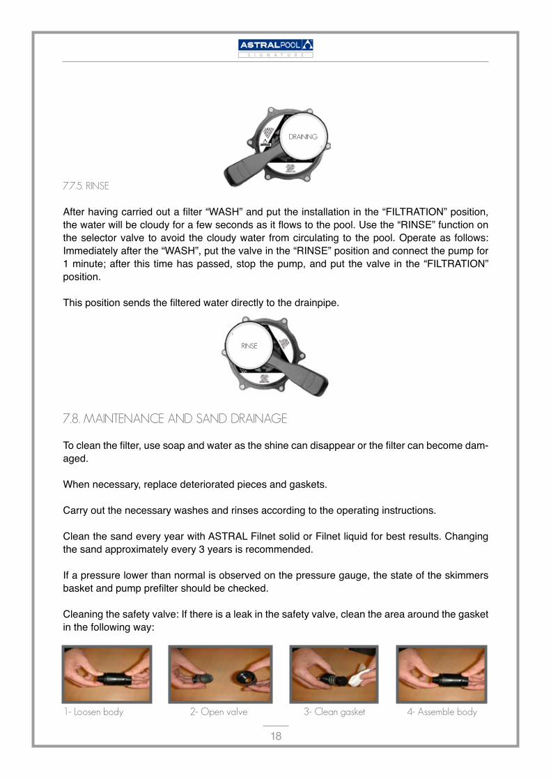
7.7.5.RINSE
After having carried out a filter “WASH” and put the installation in the “FILTRATION” position, the water will be cloudy for a few seconds as it flows to the pool. Use the “RINSE” function on the selector valve to avoid the cloudy water from circulating to the pool. Operate as follows: Immediately after the “WASH”, put the valve in the “RINSE” position and connect the pump for 1 minute; after this time has passed, stop the pump, and put the valve in the “FILTRATION” position.
This position sends the filtered water directly to the drainpipe.
7.8.MAINTENANCEANDSANDDRAINAGE
To clean the filter, use soap and water as the shine can disappear or the filter can become dam-aged.
When necessary, replace deteriorated pieces and gaskets.
Carry out the necessary washes and rinses according to the operating instructions.
Clean the sand every year with ASTRAL Filnet solid or Filnet liquid for best results. Changing the sand approximately every 3 years is recommended.
If a pressure lower than normal is observed on the pressure gauge, the state of the skimmers basket and pump prefilter should be checked.
Cleaning the safety valve: If there is a leak in the safety valve, clean the area around the gasket in the following way:
1-Loosenbody 2-Openvalve 3-Cleangasket 4-Assemblebody
RINSE
DRAINING
�9
S I G N A T U R E
7.8.1.THEWINTERPERIOD
To avoid damaging the filter over the winter period the following operations must be carried out:Do a wash and rinse according the previous instructions.
Empty the water from the filter.
Remove the filter cover to keep it ventilated during the inactive period.
When necessary, put the filter back into operation by following the instructions for COMMIS-SIONING.
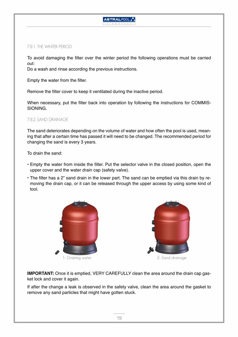
7.8.2.SANDDRAINAGE
The sand deteriorates depending on the volume of water and how often the pool is used, mean-ing that after a certain time has passed it will need to be changed. The recommended period for changing the sand is every 3 years.
To drain the sand:
Empty the water from inside the filter. Put the selector valve in the closed position, open the upper cover and the water drain cap (safety valve).The filter has a 2” sand drain in the lower part. The sand can be emptied via this drain by re-moving the drain cap, or it can be released through the upper access by using some kind of tool.
1-Drainingwater 2-Sanddrainage
IMPORTANT: Once it is emptied, VERY CAREFULLY clean the area around the drain cap gas-ket lock and cover it again. If after the change a leak is observed in the safety valve, clean the area around the gasket to remove any sand particles that might have gotten stuck.
•
•

�0
S I G N A T U R E
Product Concentration ResistantFree residual chlorine �,8 mg/l Yes
Combined chlorine 0,7 mg/l YesTotal bromine 3,5 mg/l Yes
Isocyanuric acid 90 mg/l YesAmmonia 0,6 mg/l YesNitrates �� mg/l Yes
Aluminium 0,35 mg/l YesCopper �,5 mg/l YesSilver ��,5 mg/l Yes
Problem PossibleCause Solution
The filter doesn’t flow wellBlocked prefilter Clean the prefilter
Blocked suction or propulsion tubing Clean them
The pressure rises rapidly during the filtration cycle
High water pH (cloudy water)
Decrease pH with Astral pH minor
Lack of chlorine (greenish water) Add
Pressure gauge violently oscillating
Air in the pump
Check for water leaks in the prefilter and suction tubing.
Check skimmer basket cleanliness
Suction vent semi closed Check that the suction valves are completely open
8.Chemicalresistancetable
9.Troubleshooting
��
S I G N A T U R E
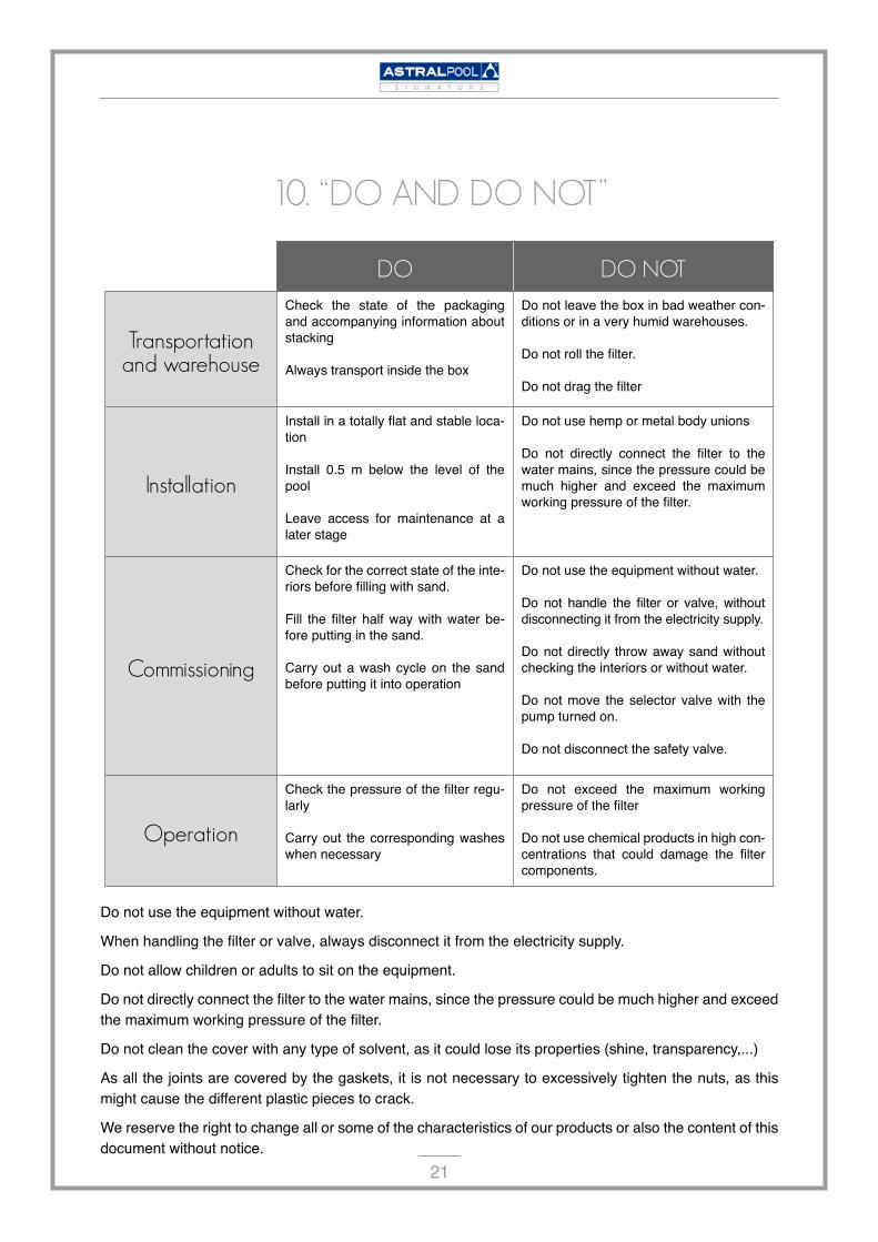
DO DONOT
Transportationandwarehouse
Check the state of the packaging and accompanying information about stacking
Always transport inside the box
Do not leave the box in bad weather con-ditions or in a very humid warehouses.
Do not roll the filter.
Do not drag the filter
Installation
Install in a totally flat and stable loca-tion
Install 0.5 m below the level of the pool
Leave access for maintenance at a later stage
Do not use hemp or metal body unions
Do not directly connect the filter to the water mains, since the pressure could be much higher and exceed the maximum working pressure of the filter.
Commissioning
Check for the correct state of the inte-riors before filling with sand.
Fill the filter half way with water be-fore putting in the sand.
Carry out a wash cycle on the sand before putting it into operation
Do not use the equipment without water.
Do not handle the filter or valve, without disconnecting it from the electricity supply.
Do not directly throw away sand without checking the interiors or without water.
Do not move the selector valve with the pump turned on.
Do not disconnect the safety valve.
Operation
Check the pressure of the filter regu-larly
Carry out the corresponding washes when necessary
Do not exceed the maximum working pressure of the filter
Do not use chemical products in high con-centrations that could damage the filter components.
Do not use the equipment without water.
When handling the filter or valve, always disconnect it from the electricity supply.
Do not allow children or adults to sit on the equipment.
Do not directly connect the filter to the water mains, since the pressure could be much higher and exceed the maximum working pressure of the filter.
Do not clean the cover with any type of solvent, as it could lose its properties (shine, transparency,...)
As all the joints are covered by the gaskets, it is not necessary to excessively tighten the nuts, as this might cause the different plastic pieces to crack.
We reserve the right to change all or some of the characteristics of our products or also the content of this document without notice.
10.“DOANDDONOT”