disc harrows - land pridelandpride.com/ari/attach/lp/public/manuals/322-013m.pdf · machine...
TRANSCRIPT

Table of Contents
Disc Harrows
DH1048, DH1060, DH1560, DH1572, DH1590, DH2572 & DH2596!Cover photo may showwith standard unit. For an Operator’s ManLanguage, please see
Read the Operator’s Manthe subsequent instructiowithout exception. Your lif
17800
322-013M
Operator’s Manualoptional equipment not supplied
ual and Decal Kit in French your Land Pride dealer.
ual entirely. When you see this symbol, ns and warnings are serious - follow e and the lives of others depend on it!
Printed 10/24/17

Machine IdentificationRecord your machine details in the log below. If you replace this manual, be sure to transfer this information to the new manual.
If you, or the dealer, have added Options not originally ordered with the machine, or removed Options that were originally ordered, the weights and measurements are no longer accurate for your machine. Update the record by adding the machine weight and measurements provided in the Specifications & Capacities Section of this manual with the Option(s) weight and measurements.
Dealer Contact Information
Model Number
Serial Number
Machine Height
Machine Length
Machine Width
Machine Weight
Delivery Date
First Operation
Accessories
Name:
Street:
City/State:
Telephone:
Email:
WARNING: Cancer and reproductive harm - www.P65Warnings.ca.gov!
Table of Contents
Table of ContentsImportant Safety Information . . . . . . . . . . . . . 1
Look For The Safety Alert Symbol . . . . . . . . . . . . . 1Safety at All Times . . . . . . . . . . . . . . . . . . . . . . . . . 1Safety Labels . . . . . . . . . . . . . . . . . . . . . . . . . . . . . 4
Introduction . . . . . . . . . . . . . . . . . . . . . . . . . . . 6Application . . . . . . . . . . . . . . . . . . . . . . . . . . . . . . . 6Using This Manual . . . . . . . . . . . . . . . . . . . . . . . . . 6Owner Assistance . . . . . . . . . . . . . . . . . . . . . . . . . . 6
Section 1: Assembly & Set-Up . . . . . . . . . . . . 8Tractor Requirements . . . . . . . . . . . . . . . . . . . . . . . 8Torque Requirements . . . . . . . . . . . . . . . . . . . . . . . 8Dealer Assembly . . . . . . . . . . . . . . . . . . . . . . . . . . . 8
DH10 & DH15 Series . . . . . . . . . . . . . . . . . . . . . . 8DH25 Series . . . . . . . . . . . . . . . . . . . . . . . . . . . . 9
Optional Equipment . . . . . . . . . . . . . . . . . . . . . . . 10ScrapersDH15 & DH25 Series Only . . . . . . . . . . . . . . . . . 10Center SweepDH15 & DH25 Series Only . . . . . . . . . . . . . . . . . 10
Tractor Hook-Up . . . . . . . . . . . . . . . . . . . . . . . . . . 11
Section 2: Operating Instructions . . . . . . . . 12Operator’s Responsibilities . . . . . . . . . . . . . . . . . . 12Transporting . . . . . . . . . . . . . . . . . . . . . . . . . . . . . 12Field Operation . . . . . . . . . . . . . . . . . . . . . . . . . . . 13General Operating Instructions . . . . . . . . . . . . . . . 13
Section 3: Adjustments . . . . . . . . . . . . . . . . . 14Disc Angling . . . . . . . . . . . . . . . . . . . . . . . . . . . . . 14Disc Gang Lateral Adjustment . . . . . . . . . . . . . . . . 15
Front Disc Gangs on DH10 Series . . . . . . . . . . . 15Front Disc Gangs on DH15 Series . . . . . . . . . . . 15Front Disc Gangs on DH25 Series . . . . . . . . . . . 15Rear Disc Gangs on DH10 Series . . . . . . . . . . . 15Rear Disc Gangs on DH15 Series . . . . . . . . . . . 15Rear Disc Gangs on DH25 Series . . . . . . . . . . . 15Disc Leveling Front To Rear . . . . . . . . . . . . . . . 15
Disc Blade Replacement . . . . . . . . . . . . . . . . . . . . 15
Section 4: Accessories . . . . . . . . . . . . . . . . . 16Electric Spin Spreader . . . . . . . . . . . . . . . . . . . . 16Drag Harrow . . . . . . . . . . . . . . . . . . . . . . . . . . . 16Seed Bed Roller . . . . . . . . . . . . . . . . . . . . . . . . . 16Complete One Pass Seeding Application . . . . . 17
Section 5: Maintenance . . . . . . . . . . . . . . . . . 18General Maintenance Information . . . . . . . . . . . . . 18Daily Operational Checks . . . . . . . . . . . . . . . . . . . 18Lubrication . . . . . . . . . . . . . . . . . . . . . . . . . . . . . . 18Long-Term Storage . . . . . . . . . . . . . . . . . . . . . . . . 18
10/24/17
© Copyright 2017 All rights Reserved
Land Pride provides this publication “as is” without warranty opreparation of this manual, Land Pride assumes no responsibilityof the information contained herein. Land Pride reserves the righproduct at the time of its publication, and may not reflect the pro
Land
All other brands and product names are
Printed
DH1048, DH1060
Section 6: Specifications & Capacities . . . . . 19Section 7: Features & Benefits . . . . . . . . . . . 22Section 8: Troubleshooting . . . . . . . . . . . . . . 24Section 9: Torque Values Chart . . . . . . . . . . . 26Section 10: Warranty . . . . . . . . . . . . . . . . . . . 27
f any kind, either expressed or implied. While every precaution has been taken in the for errors or omissions. Neither is any liability assumed for damages resulting from the uset to revise and improve its products as it sees fit. This publication describes the state of thisduct in the future.
Pride is a registered trademark.
trademarks or registered trademarks of their respective holders.
in the United States of America.
, DH1560, DH1572, DH1590, DH2572 & DH2596 Disc Harrows 322-013M

See previous page for Table of contents.
DH10 Series
Manual QR LocatorThe QR (Quick Reference) codes on the cover and below wilParts Manual. Download the appropriate App on your cameraApp, point your phone on the QR code, and take a picture.
10/24/17
DH15 & DH25 Series
Dealer QR LocatorThe QR code below will link you to available dealers for Land Pride products.
l take you to the phone, open the

Important Safety Information
10/24/17 1
Important Safety InformationThese are common practices that may or may not be applicable to the products described in this manual.
Tractor Shutdown & Storage If engaged, disengage power
take-off. Park on solid, level ground and
lower implement to ground or onto support blocks.
Put tractor in park or set park brake, turn off engine, and remove switch key to prevent unauthorized starting.
Relieve all hydraulic pressure to auxiliary hydraulic lines.
Wait for all components to stop before leaving operator’s seat.
Use steps, grab-handles and skid-resistant surfaces when getting on and off the tractor.
Detach and store implement in an area where children normally do not play. Secure implement using blocks and supports.
OFF REMOVE
Look For The Safety Alert SymbolThe SAFETY ALERT SYMBOL indicates there is a potential hazard to personal safety involved and extra safety precaution must be taken. When you see this symbol, be alert and carefully read the message that follows it. In addition to design and configuration of equipment, hazard control, and accident prevention are dependent upon the awareness, concern, prudence, and proper training of personnel involved in the operation, transport, maintenance, and storage of equipment.
!
Safety Precautions for ChildrenTragedy can occur if the operator is not alert to the presence of children, Children generally are attracted to implements and their work. Never assume children will remain
where you last saw them. Keep children out of the work area
and under the watchful eye of a responsible adult.
Be alert and shut the implement and tractor down if children enter the work area.
Never carry children on the tractor or implement. There is not a safe place for them to ride. They may fall off and be run over or interfere with the control of the power machine.
Never allow children to operate the power machine, even under adult supervision.
Never allow children to play on the power machine or implement.
Use extra caution when backing up. Before the tractor starts to move, look down and behind to make sure the area is clear.
Safety at All TimesCareful operation is you best insurance against an accident. All operators, no matter how much experience they may have, should carefully read this manual and other related manuals before operating the power machine and this implement. It is the owner’s obligation to instruct all operators in safe operation. Thoroughly read and understand
the “Safety Label” section, read all instructions noted on them.
Do not operate the equipment while under the influence of drugs or alcohol as they impair the ability to safely and properly operate the equipment.
The operator should be familiar with all functions of the tractor and attached implement, and be able to handle emergencies quickly.
Make sure all guards and shields are in place and secured before operating implement.
Keep all bystanders away from equipment and work area.
Start tractor from the driver’s seat with hydraulic controls in neutral.
Operate tractor and controls from the driver’s seat only.
Never dismount from a moving tractor or leave tractor unattended with engine running.
Do not allow anyone to stand between tractor and implement while backing up to implement.
Keep hands, feet, and clothing away from power-driven parts.
While transporting and operating equipment, watch out for objects overhead and along side such as fences, trees, buildings, wires, etc.
Do not turn tractor so tight as to cause hitched implement to ride up on the tractor’s rear wheel.
Store implement in an area where children normally do not play.
Be Aware of Signal WordsA Signal word designates a degree or level of hazard seriousness. The signal words are:
Indicates a hazardous situation that, if not avoided, will result in death or serious injury. This signal word is to be limited to the most extreme situations.
! DANGER
Indicates a hazardous situation that, if not avoided, could result in death or serious injury.
Indicates a hazardous situation that, if not avoided, could result in minor or moderate injury.
! WARNING
! CAUTION

Important Safety Information
2
These are common practices that may or may not be applicable to the products described in this manual.
Use A Safety Chain A safety chain will help control
drawn machinery should it separate from the tractor drawbar.
Use a chain with the strength rating equal to or greater than the gross weight of the towed implement.
Attach the chain to the tractor drawbar support or other specified anchor location. Allow only enough slack in the chain to permit turning.
Always hitch the implement to the machine towing it. Do not use the safety chain tow the implement.
Tire Safety Tire changing can be dangerous
and must be performed by trained personnel using the correct tools and equipment.
Always maintain correct tire pressure. Do not inflate tires above recommended pressures shown in the Operator’s Manual.
When inflating tires, use a clip-on chuck and extension hose long enough to allow you to stand to one side and NOT in front of or over the tire assembly. Use a safety cage if available.
Securely support the implement when changing a wheel.
When removing and installing wheels, use wheel handling equipment adequate for the weight involved.
Make sure wheel bolts have been tightened to the specified torque.
Practice Safe Maintenance Understand procedure before doing
work. Refer to the Operator’s Manual for additional information.
Work on a level surface in a clean dry area that is well-lit.
Use properly grounded electrical outlets and tools.
Use correct tools and equipment for the job that are in good condition.
Lower implement to the ground and follow all shutdown procedures before leaving the operator’s seat to perform maintenance.
Allow equipment to cool before working on it.
Disconnect battery ground cable (-) before servicing or adjusting electrical systems or before welding on implement.
Do not grease or oil implement while it is in operation.
Inspect all parts. Make certain parts are in good condition & installed properly.
Replace parts on this implement with genuine Land Pride parts only. Do not alter this implement in a way which will adversely affect its performance.
Remove buildup of grease, oil, or debris.
Remove all tools and unused parts from equipment before operation.
Transport Safely Comply with state and local laws. Use towing vehicle and trailer of
adequate size and capacity. Secure equipment towed on a trailer with tie downs and chains.
Sudden braking can cause a towed trailer to swerve and upset. Reduce speed if towed trailer is not equipped with brakes.
Avoid contact with any over head utility lines or electrically charged conductors.
Always drive with load on end of loader arms low to the ground.
Always drive straight up and down steep inclines with heavy end of a tractor with loader attachment on the “uphill” side.
Engage park brake when stopped on an incline.
Maximum transport speed for an attached equipment is 20 mph. DO NOT EXCEED. Never travel at a speed which does not allow adequate control of steering and stopping. Some rough terrains require a slower speed.
As a guideline, use the following maximum speed weight ratios for attached equipment:
20 mph when weight of attached equipment is less than or equal to the weight of machine towing the equipment.10 mph when weight of attached equipment exceeds weight of machine towing equipment but not more than double the weight.
IMPORTANT: Do not tow a load that is more than double the weight of the vehicle towing the load.
10/24/17

Important Safety Information
10/24/17 3
These are common practices that may or may not be applicable to the products described in this manual.
Avoid High Pressure Fluids Hazard Escaping fluid under pressure can
penetrate the skin causing serious injury.
Before disconnecting hydraulic lines or performing work on the hydraulic system, be sure to release all residual pressure.
Make sure all hydraulic fluid connections are tight and all hydraulic hoses and lines are in good condition before applying pressure to the system.
Use a piece of paper or cardboard, NOT BODY PARTS, to check for suspected leaks.
Wear protective gloves and safety glasses or goggles when working with hydraulic systems.
DO NOT DELAY. If an accident occurs, see a doctor familiar with this type of injury immediately. Any fluid injected into the skin or eyes must be treated within a few hours or gangrene may result.
Wear Protective Equipment Wear protective clothing and
equipment appropriate for the job such as safety shoes, safety glasses, hard hat, and ear plugs.
Clothing should fit snug without fringes and pull strings to avoid entanglement with moving parts.
Prolonged exposure to loud noise can cause hearing impairment or hearing loss. Wear suitable hearing protection such as earmuffs or earplugs.
Operating equipment safely requires the operator’s full attention. Avoid wearing headphones while operating equipment.
Use Seat Belt and ROPS Land Pride recommends the use
of a CAB or roll-over-protective-structures (ROPS) and seat belt in almost all power machines. Combination of a CAB or ROPS and seat belt will reduce the risk of serious injury or death if the power machine should be upset.
If ROPS is in the locked-up position, fasten seat belt snugly and securely to help protect against serious injury or death from falling and machine overturn.
Keep Riders Off Machinery Never carry riders or use tractor
to lift or transport individuals. There is not a safe place for a
person to ride. Riders obstruct operator’s view
and interfere with the control of the power machine.
Riders can be struck by objects or thrown from the equipment.
Avoid Underground Utilities Dig Safe, Call 811 (USA).
Always contact your local utility companies (electrical, telephone, gas, water, sewer, and others) before digging so that they may mark the location of any underground services in the area.
Be sure to ask how close you can work to the marks they positioned.
Prepare for Emergencies Be prepared if a fire starts. Keep a first aid kit and fire
extinguisher handy. Keep emergency numbers for
doctor, ambulance, hospital, and fire department near phone.
911
Use Safety Lights and Devices Slow moving tractors, skid steers,
self-propelled machines, and towed equipment can create a hazard when driven on public roads. They are difficult to see, especially at night. Use the Slow Moving Vehicle sign (SMV) when on public roads.
Flashing warning lights and turn signals are recommended whenever driving on public roads.

Table of Contents
Safety LabelsYour Disc Harrow comes equipped with all safety labels in place. They were designed to help you safely operate your equipment. Read and follow their directions.
1. Keep all safety labels clean and legible.2. Refer to this section for proper label placement. Replace
all damaged or missing labels. Order new labels from your nearest Land Pride dealer. To find your nearest dealer, visit our dealer locator at www.landpride.com.
3. Some new equipment installed during repair requires safety labels to be affixed to the replaced component as
specified by Land Pride. When ordering new components make sure the correct safety labels are included in the request.
4. Refer to this section for proper label placement. To install new labels:a. Clean surface area where label is to be placed.
b. Spray soapy water onto the cleaned area.
c. Peel backing from label and press label firmly onto the surface.
d. Squeeze out air bubbles with edge of a credit card or with a similar type of straight edge.
DH1048, DH1060, DH1560, DH1572, DH1590, DH2572 & DH2596 Disc Harrows 322-013M 10/24/174
818-719CCaution General
DH10 Series
2375523753
DH15 & DH25 Series
17800

Table of Contents
DH1048, DH1060, DH1560, DH1572, DH1590, DH2572 & DH2596 Disc Harrows 380-192M10/24/17 5
838-093CWarning Sharp Object
838-614C 2" x 9" Red Reflector (2 places on DH1590 & DH2596)
858-095C 2" x 4 1/2" Red Reflector (2 places on DH1048, DH1060, DH1560, DH1572, & DH2572)17801
DH10 & DH15 Series
DH25 Series
23753
25847
Warning Decals on end of Disc Gangs are for Set-up Only. Location may vary from gang to gang.The customer is not required to maintain them once worn off.
IntroductionTable of Contents
Introduction
Land Pride welcomes you to the growing family of new product owners. This Disc Harrow has been designed with care and built by skilled workers using quality materials. Proper assembly, maintenance, and safe operating practices will help you get years of satisfactory use from this machine.ApplicationThe DH10 Series Economy Disc Harrows are designed to open up and break up the soil surface and to prepare the soil for seedbed or planting preparation. The DH10 Series Discs are adapted for Category 1 three-point hitch mounting on tractors in the 20-40 HP range, and are Quick Hitch adaptable. The forward gang has aggressive notched discs while the rear gang has a choice of notched or smooth discs to quickly break up and evenly redistribute the finely cultivated topsoil. The DH10 Series Land Pride Discs have applications in homeowner landscaping, smaller nurseries, gardens, smaller hobby farms, wild game food plots, and medium duty residential use. The 48" Disc Harrow features 16" disks, while the 60" offers 16" or 18".
The DH15 Series Disc Harrows are designed to breakup and redistribute the soil surface in preparation of seedbeds for planting operations. The DH15 Series Discs are adapted for Category 1 three-point hitch on tractors in the 25-65 HP range, and are Quick Hitch adaptable. Disc gangs can be ordered with smooth or notched disc gang arrays for lighter or more aggressive applications based on customer needs. The DH15 Series Disc Harrows have applications in commercial landscaping, nurseries, large gardens, farms, and municipal beautification programs.
The DH25 Series Disc Harrows are designed to breakup and redistribute the soil surface in preparation of seedbed and field planting operations. The DH25 Series Discs are adapted for category 1 and 2 three-point hitch on tractors in the 35-100 HP range, and are Quick Hitch adaptable. Disc gangs can be ordered with smooth or notched disc gang arrays for lighter or more aggressive applications and this series does offer 20" diameter or larger 22" diameter discs to meet specific customer needs. The DH25 Series Disc Harrows have applications in commercial landscaping, construction, farms, ranches, and municipal maintenance programs.
See “Specifications & Capacities” on page 19 and “Features & Benefits” on page 22 for additional information and performance enhancing options.
DH1048, DH1060, DH1560, DH1572, DH1590, DH2572 & DH2596 D6
Using This Manual• This Operator’s Manual is designed to help familiarize
the operator with safety, assembly, operation, adjustments, troubleshooting, and maintenance. Read this manual and follow the recommendations to help ensure safe and efficient operation.
• The information contained within this manual was current at the time of printing. Some parts may change slightly to assure you of the best performance.
• To order a new Operator’s or Parts Manual, contact your authorized dealer. Manuals can also be downloaded, free-of-charge, from our website at www.landpride.com
Terminology“Right” or “Left” as used in this manual is determined by facing forward in the direction the machine will operate while in use unless otherwise stated.
Definitions
Owner AssistanceThe Online Warranty Registration should be completed by the dealer at the time of purchase. This information is necessary to provide you with quality customer service.
The parts on your Disc Harrow have been specially designed by Land Pride and should only be replaced with genuine Land Pride parts. Contact a Land Pride dealer if customer service or repair parts are required. Your Land Pride dealer has trained personnel, repair parts, and equipment needed to service the implement.
IMPORTANT: A special point of information related to the following topic. Land Pride’s intention is this information must be read & noted before continuing.
NOTE: A special point of information that the operator should be aware of before continuing.
isc Harrows 322-013M 10/24/17
IntroductionTable of Contents
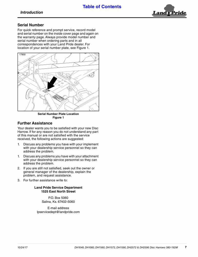
Serial NumberFor quick reference and prompt service, record model and serial number on the inside cover page and again on the warranty page. Always provide model number and serial number when ordering parts and in all correspondences with your Land Pride dealer. For location of your serial number plate, see Figure 1.
Serial Number Plate LocationFigure 1
Further AssistanceYour dealer wants you to be satisfied with your new Disc Harrow. If for any reason you do not understand any part of this manual or are not satisfied with the service received, the following actions are suggested:
1. Discuss any problems you have with your implement with your dealership service personnel so they can address the problem.
1. Discuss any problems you have with your attachment with your dealership service personnel so they can address the problem.
2. If you are still not satisfied, seek out the owner or general manager of the dealership, explain the problem, and request assistance.
3. For further assistance write to:
Land Pride Service Department1525 East North Street
P.O. Box 5060Salina, Ks. 67402-5060
E-mail [email protected]
17800
DH1048, DH1060, DH1560, DH1572, DH1590, DH2572 & DH2596 Disc Harrows 380-192M10/24/17 7

Section 1: Assembly & Set-UpTable of Contents
Section 1: Assembly & Set-Up
Tractor RequirementsTractor 3-Point hitch Category and horsepower should match your Disc Harrow Series.
• DH10 Series3-Point Hitch. . . . . . . Category 1Horsepower . . . . . . . 20-40 HP
• DH15 Series 3-Point Hitch. . . . . . . Category 1Horsepower . . . . . . . 25-65 HP
• DH25 Series3-Point Hitch. . . . . . . Category 1 & 2Horsepower . . . . . . . 35-100 HP
! WARNINGTo prevent serious injury or death:
Lightweight tractors with rear attached implements may need weights added to the front to maintain steering control and prevent serious injury or death. Consult your tractor Operator’s Manual to determine proper weight requirements and maximum weight limitations.
Torque RequirementsRefer to “Torque Values Chart” on page 26 to determine correct torque values for common bolts. See “Additional Torque Values” at bottom of chart for exceptions to standard torque values.
DH1048, DH1060, DH1560, DH1572, DH1590, DH2572 & DH2596 D8
Dealer Assembly Figur
18764
Dealer AssemblyDH10 & DH15 Series
! WARNINGTo prevent serious injury or death:
Be careful when working with Disc blades as the edges are sharp. Wear gloves when working around disc blades!
Refer to Figure 1-11. Unpack Disc Harrow from shipping crate.
2. Attach 3-Point straps (#1 & #2) to front lower lifting lugs using 7/8" hitch pins (#3), lock washers (#4), and 7/8" -14 hex nuts (#5). Do not tighten.
3. Attach 3-Point brace (#6) to the harrow’s center beam with 3/4" -10 x 4 1/2" GR5 hex head cap screw (#7) and 3/4" lock nut (#8). Do not tighten.
4. Insert 3/4" -10 x 4 1/2" hex head bolt (#9) through the left side of 3-Point brace (#6), left 3-Point strap (#1), spacer (#10), right 3-Point strap (#2), and right side of 3-Point brace (#6). Secure bolt with 3/4" lock nut (#5). Do not tighten.
5. Insert 3/4" clevis pin (#12) through upper holes in 3-Point straps (#1 & #2). Secure clevis pin with hairpin cotter (#13).
6. Tighten all attaching hardware to the correct torque.
isc Harrows 322-013M 10/24/17
(DH1560 Shown)e 1-1

Section 1: Assembly & Set-UpTable of Contents
DH25 SeriesRefer to Figure 1-2:
! WARNINGTo prevent serious injury or death:
Be careful when working with Disc blades as the edges are sharp. Wear gloves when working around disc blades!
1. Unpack Disc Harrow from shipping crate.
2. Assemble 3-Point hitch as shown in Figure 1-2.
a. Align upper straps (#3) and rear brace (#8) as shown.
b. Place spacer (#1) between upper straps (#3). Secure spacer with 3/4"-10 x 5" GR5 bolt (#10) and lock nut (#12).
3. Remove bolts (#10), lock nuts (#12), spacers (#2), and bottom brackets (#4).
DH1048, DH1060, DH15610/24/17
Dealer Assembly Figur
18764
4. Insert swing arms (#6) through slots in mainframe (#7). Re-install 3/4"-10 x 5" GR5 bolts (#10), locknuts (#12), spacers (#2), and bottom brackets (#4) as shown.
5. Assemble disc gangs (#9) to main frame (#7) with 5/8" u-bolts (#14) and hex flange lock nuts (#13). See “Disc Gang Lateral Adjustment” on page 15 for proper spacing.
6. Tighten hex flange lock nuts (#13) to the correct torque.
7. Install plastic end caps (#15) in swing arms (#6). Use a bead of silicone on the inside lip of the tubing prior to cap installation. This will help lock caps in place.
IMPORTANT: The next procedure will require lifting mainframe frame (#7). A forklift or adequate lifting device is recommended.
0, DH1572, DH1590, DH2572 & DH2596 Disc Harrows 380-192M 9
(DH2572 Shown)e 1-2

Section 1: Assembly & Set-UpTable of Contents
Optional EquipmentScrapersDH15 & DH25 Series OnlyRefer to Figure 1-3:Install Scraper Assemblies (#1) and (#2) using instruction manual No. 322-042M included with scraper kit.
Center SweepDH15 & DH25 Series OnlyRefer to Figure 1-4:Assemble Center Sweep to the center tube of the Disc Harrow Frame.
1. Clamp sweep arm (#8) to center frame with spring bracket (#1), two 5/8"-11 u-bolts (#6), and 5/8"-11 flange lock nuts (#4).
2. Tighten hex flange lock nuts (#4) to the correct torque.
3. Attach 9" cultivator sweep (#7) to sweep arm (#8) with 7/16-14 GR5 plow bolts (#2), lock washer (#5), and 7/16"-14 hex nuts (#3).
4. Tighten 7/16" hex nuts to the correct torque.
DH1048, DH1060, DH1560, DH1572, DH110
Scrapers AssemblyFigure 1-3
Center Sweep AssemblyFigure 1-4
19759
20562
590, DH2572 & DH2596 Disc Harrows 322-013M 10/24/17

Section 1: Assembly & Set-UpTable of Contents
Tractor Hook-Up
! WARNINGTo prevent serious injury or death:
A Crushing Hazard exists while hooking-up and unhooking implement. Keep people and animals away while backing-up to implement or pulling away from implement. Do not operate hydraulic controls while a person or animal is directly behind the tractor or near the implement.
NOTE: Land Pride’s Quick Hitch can be attached to the tractor to provide quick and easy 3-point hook-up and detachment. See your nearest Land Pride dealer to purchase a Quick-Hitch.
DH1048, DH1060, DH15610/24/17
Tractor HFigur
17809
Refer to Figure 1-5:1. Check tractor draw bar to make certain it will not
interfere with raising and lowering the Disc Harrow. Move draw bar ahead or remove if required. Draw bar should also be rechecked for clearance when raising and lowering the unit for the first time.
2. Align lower link arms of tractor to hitch pins (#1) on Disc Harrow. Insert lower hitch pins into hitch holes n lower 3-point lift arms and secure in place with linchpins (#2) (supplied by customer).
3. Attach tractor top center link to upper hitch of Disc Harrow with hitch pin (#3) and secure with hairpin cotter (#4).
4. Use lower bushing “A” when using a Cat.1 Quick Hitch for tractor hook-up.
0, DH1572, DH1590, DH2572 & DH2596 Disc Harrows 380-192M 11
ook-Upe 1-5
17809
A

Section 2: Operating InstructionsTable of Contents
Section 2: Operating Instructions• Never make contact with underground utilities such as
Operator’s ResponsibilitiesHazard control and accident prevention are dependent upon the awareness, concern, prudence, and proper training involved in the operation, transport, storage, and maintenance of the Disc Harrow. Therefore, it is absolutely essential that no one operates the harrow unless they are age 16 or older and have read, fully understood, and are totally familiar with the Operator’s Manual. Make sure the operator has paid particular attention to:
• Important Safety Information, page 1
• Section 1: Assembly & Set-Up, page 8
• Section 2: Operating Instructions, page 12
• Section 3: Adjustments, page 14
• Section 5: Maintenance, page 18
Perform the following inspections before using your Disc Harrow.
! WARNINGTo avoid serious injury or death:
• Allow only persons to operate this implement who have fully read and comprehended this manual, who have been properly trained in the safe operation of this implement, and who are age 16 or older. Serious injury or death can result from the inability to read, understand, and follow instructions provided in this manual.
• Do not allow anyone near the tractor or attached implement while operating. Stop operation if bystanders are too close. They can be hit by flying projectiles, become entangled in the equipment, or ran over causing serious injury or death.
• Never carry riders on the implement or tractor unless the tractor is equipped with a passenger seat for the rider to sit in. Follow manufacturer's recommendations when using the passenger seat. Except for the passenger seat, there is not a safe place for a person to ride. Riders obstruct the operator’s view, interfere with control of the equipment, and can be struck by objects or thrown from the equipment.
• Do not use implement to lift objects; to pull objects such as fence posts, stumps, etc; or to push objects. The unit is not designed or guarded for these uses.
Operating Checklist Check Ref.
Read “Important Safety Information” 1
Read all of the tractor hook-up and preparation instructions. 11
Read “Operating Instructions” 12
Check harrow initially and periodically for loose bolts & pins. Pay special attention to disc gang hanger bolts and axle nuts. Refer to Torque values Chart for torque values.
26
DH1048, DH1060, DH1560, DH1572, DH1590, DH2572 & DH2596 D12
electrical power lines, gas lines, phone lines, etc. They can cause serious injury or death from electrocution, explosion, or fire. If in doubt, call your local utility companies before digging so that they can mark the location of underground services in the area. For contact information, see Dig Safe in the “Important Safety Information” starting on page 1.
• Do not alter implement or replace parts on the implement with other brands. Other brands may not fit properly or meet OEM specifications. They can weaken the integrity and impair the safety, function, performance, and life of the implement. Replace parts only with genuine OEM parts.
• Perform scheduled maintenance. Check for loose hardware, missing parts, broken parts, structural cracks, and high wear. Make repairs before putting implement back into service. Serious breakdowns can result in injury or death.
• Keep everyone away from the Disc Harrow while raising, lowering, and transporting the implement to protect against falling blade hazard.
Transporting
! WARNINGTo prevent serious injury or death:
When traveling on public roads, use LED lights, SMV sign, clean reflectors, and other adequate devices to warn operators in other vehicles of your presence. If implement blocks visibility of SMV sign, relocate SMV sign so it is visible from the back at all times. Always comply with all federal, state, and local laws.
1. Lift Disc Harrow as high as possible to make sure it clears the ground in transportation.
2. Never transport with negative or insufficient front tractor weight. Doing so can result in loss of steering control. If needed, add ballast to the tractor. Refer to tractor Operator’s Manual for recommendations.
3. When traveling on roadways, transport in such a way that faster moving vehicles may pass you safely.
4. Do not lower unit while transporting on pavement, blacktop or road. Damage to unit and/or road may occur.
5. Select a safe ground travel speed when transporting from one area to another.
6. Be sure to reduce tractor ground speed when turning; and, leave enough clearance so the Disc Harrow does not contact obstacles such as buildings, trees, or fences.
7. When traveling over rough or hilly terrain, shift tractor to a lower gear.
IMPORTANT: Make sure all safety labels are in their proper location and in good condition before operation. Follow all directions on the safety labels.
isc Harrows 322-013M 10/24/17

Section 2: Operating InstructionsTable of Contents
Field Operation
! CAUTIONTo prevent serious injury:
Be careful when working with Disc blades as the edges are sharp. Wear gloves when working around disc blades!
1. After initial adjustments have been made with tractor hooked to the Disc Harrow, you are ready to start discing.
2. Lower Disc Harrow to the ground and start moving forward. Your travel speed will be determined by soil conditions. You may find that you will want to change the disc angle to do the job right. Refer to “Disc Angling” on page 14 for detailed instructions.
3. Always lift unit out of ground when turning.
4. Do not disc in reverse (traveling backwards). The Disc Harrow is designed for working soil while traveling forward only. Damage to the harrow may occur. Recommended procedure for working corners or other tight places is:
a. Lift unit up.
b. Back unit into the corner or other tight areas.
c. Lower unit down and proceed forward with disc in the ground.
5. Refer to Figure 2-1: Always cross steep ditches and banks on the diagonal! Never cross straight across! Damage to the disc and/or tractor may occur while crossing straight across.
Figure 2-1
IMPORTANT: The harrow can be damaged if it is not lifted out of the ground before making sharp turns and before backing-up.
IMPORTANT: do not cross straight across steep ditches and banks. Damage to the disc and/or tractor may occur while crossing straight across.
Ditch / Bank
Ditch / Bank
Incorrect Crossing (Straight Across)
Correct Crossing (On the diagonal)
DH1048, DH1060, DH15610/24/17
General Operating InstructionsBefore putting your Land Pride Disc Harrow into service you must thoroughly review the Operator’s Manual. Once you have read the Operator’s Manual and properly mounted your Land Pride Disc Harrow on your tractor, you should be ready to head for the work site. You should have already removed any sizable tree limbs, rocks, or debris from this area. Do not attempt to disc wet or mucky soil and all areas should be well drained and capable of being walked on without having the soil stick to your shoes.
Discing action will commence as soon as the unit touches the ground and tractor begins to move forward. Your travel speed forward will be determined by soil conditions and available tractor horsepower. Never try to disc in reverse and when you reach the end of a pass, pick the unit up before turning. Trying to turn sharply with the unit in the ground will cause extreme side loading on the discs and may cause damage. Making disc gang adjustments is relatively easy by raising the disc off of the ground, placing safety blocks under the frame, pulling the locking pin, making the required adjustment, and then reverse the process till you are back in action. The operator’s manual illustrates this process very clearly.
Ground conditions and the finish you require will determine how you position the angles of your front and rear disc gangs. Both of the front and rear disc gangs have four angle adjustment positions. The best ground finish will usually be achieved when the rear gang is set at a slightly lesser angle than the front gang. The more aggressive you set the angle of the gangs, the more aggressive the cutting action in the soil profile will be. The more aggressive the cutting action is, the more horsepower will be required to pull your unit. Achieving the desired effect may require a little experimentation in your given conditions. If the soil is building up on or sticking to your discs then the soil is too wet and discing operations should be discontinued until the ground is dry and more workable.
Once you are finished using your disc, park it on a dry and level surface, clean it, and make it ready for the next use. With a little practice you will be able to achieve excellent results from your Land Pride Disc Harrow. See “Features and Benefits” section or “Product Specifications” for additional information and performance enhancing options.
0, DH1572, DH1590, DH2572 & DH2596 Disc Harrows 380-192M 13

Section 3: AdjustmentsTable of Contents
Section 3: Adjustments
Disc AnglingRefer to Figure 3-1:
! WARNINGTo prevent serious injury or death:
• Perform maintenance only on equipment that is not running. Place tractor in park or set park brake, shut tractor engine off, remove switch key, and wait for all moving components to come to a complete stop before dismounting tractor.
• Properly block and secure Disc Harrow in lift position prior to changing angles of gangs or during maintenance. Keep feet from under disc blades during adjustments or maintenance.
• Be careful when working with disc blades as the edges are sharp. Wear gloves when working around disc blades!
NOTE: The more angle you have on the disc, the more aggressive the cut will be, and the more horsepower will be required to pull your unit.
DH1048, DH1060, DH1560, DH1572, DH1590, DH2572 & DH2596 D14
Disc AdFigu
17867
The Disc Harrow is designed with handles (#2) to make disc gang angle adjustments easy. Adjust disc gangs as follows:
• DH10 Series: Remove hitch pin (#1). Slide handle (#2) to desired position and replace hitch pin.
• DH15 & DH25 Series: Remove hitch pin (#1) and hair pin cotter (#3). Slide handle (#2) to desired position and replace hitch pin and hair pin cotter.
NOTE: For a better ground finish, angle the rear gangs at a lesser angle than the front gangs.
The front discs on all series have four angle positions: (0, 7, 14, and 21 degrees.)
The rear discs on DH10 and DH15 Series have four angle positions: (0, 7, 14, and 21 degrees.)
The rear discs on DH25 Series have three angle positions: (7, 14, and 21 degrees.)
isc Harrows 322-013M 10/24/17
justmentsre 3-1
Pin (#1) is secured with a ball- detent on DH10 Series. All other Series uses the hair pin cotter (#3) to secure the pin.

Section 3: AdjustmentsTable of Contents
Disc Gang Lateral AdjustmentRefer to Figure 3-2:Additional adjustments can be made by loosening u-bolts (#1) and sliding disc gangs in or out to desired position.
Disc AdjustmentsFigure 3-2
Front Disc Gangs on DH10 SeriesThe recommended position for the front disc gangs (at ground contact point) is 8 1/4" between inside gang disc blades and equally spaced on either side of center frame tube. Tighten u-bolts after adjustment.
Front Disc Gangs on DH15 SeriesThe recommended position for the front disc gangs (at ground contact point) is 7 1/2" between inside gang disc blades and equally spaced on either side of center frame tube. Tighten u-bolts after adjustment.
Front Disc Gangs on DH25 SeriesThe recommended position for the front disc gangs (at ground contact point) is 9 1/2" between inside gang disc blades and equally spaced on either side of center frame tube. Tighten u-bolts after adjustment.
Rear Disc Gangs on DH10 SeriesThe recommended position for the rear disc gangs (at ground contact point) is 17 1/4" between inside disc blades and equally spaced on either side of center frame tube. Tighten u-bolts after adjustment.
NOTE: The rear discs should be centered between the front discs for optimum performance.
17805
DH1048, DH1060, DH15610/24/17
Rear Disc Gangs on DH15 SeriesThe recommended position for the rear disc gangs (at ground contact point) is 15" between inside disc blades and equally spaced on either side of center frame tube. Tighten u-bolts after adjustment.
Rear Disc Gangs on DH25 SeriesThe recommended position for the rear disc gangs (at ground contact point) is 17" between inside disc blades and equally spaced on either side of center frame tube. Tighten u-bolts after adjustment.
Disc Leveling Front To RearThe truest way to level your disc from front to rear is to observe behind the center of the Disc Harrow. In most soil conditions, a slight ridge in the center is actually a level operation. More air pockets will form where soil is thrown against each other, causing a small ridge to from that will disappear after a soaking rain.
1. If unit is leaving a significant ridge in the center, raise disc rear gangs by shortening the center 3-Point link.
2. If unit is leaving a furrow (valley) in the center, lower rear disc gangs by lengthening the center 3-Point link.
3. See also Section 8: Troubleshooting for helpful solutions to leveling the Disc Harrow.
Disc Blade ReplacementRefer to Figure 3-3:When replacing notched disc blades, assemble disc blades in a spiral pattern.
Disc Replacement (Spiral)Figure 3-3
17802
0, DH1572, DH1590, DH2572 & DH2596 Disc Harrows 380-192M 15

Section 4: AccessoriesTable of Contents
Land Pride Drag Harrow ModelsSection 4: Accessories
Electric Spin SpreaderRefer to Figure 4-1:The Land Pride Electric Spin Spreader is a highly versatile package designed to plant or spread seeds, fertilizer, lime, gypsum, and other soil conditioning amendments at distances ranging from 4 ft. to 20 ft. It can also be used in the off-season to spread sand or salt for winter icing or slick snow conditions.
The unit has a 12 Volt remote tether control that can be operated right from the driver seat to turn the spreader on or off or to set the seed-gate opening to different application rates.
The Spin Spreader has applications in overseeding of pastures, grassy runways, open areas, roadsides, medians, wild game food plots, hunting clubs, hunting resorts, ranches, farms, game preserves, landscaping, and hobby farming. It also works very well in gardens and nurseries to incorporate fertilizer and pelletized gypsum or lime as soil amendments.
Accessories are available for mounting the spreader to a 2" receiver hitch on a utility vehicle or to a Land Pride Disc Harrow. A rear hitch can be attached to the Spin Spreader mounting bracket for the Disc Harrow. The Disc Harrow and Seed Bed Roller can then be hitched to the rear hitch. See “Complete One Pass Seeding Application” on page 17.
Electric Spin Spreader, Mounting Bracket & Rear HitchFigure 4-1
Drag HarrowRefer to Figure 4-2: The Land Pride Drag Harrows are designed for various types of seedbed and ground preparations. They can be used to smooth out freshly cultivated soil, work seed and fertilizer into freshly cultivated soil or into turf and pasture grass, fluff and level arenas, aerate soil for faster dry-downtime, dethatch and aerate lawns and pastures, break up aeration cores on turf surfaces, and groom snow-packed ski resorts.
The Drag Harrow can also be used in tandem with Land Pride’s Disc Harrow, Electric Spin Spreader, and Seed Bed Roller to provide a highly efficient and complete seeding application in one pass. See “Complete One Pass Seeding Application” on page 17.
Rear HitchSpin Spreader Mounting
25609
DH1048, DH1060, DH1560, DH1572, DH1590, DH2572 & DH2596 D16
Model DRG04 . . . . . . . . . . . . . . . . 4 ft. wide x 4 ft. longModel DRG06 . . . . . . . . . . . . . . . . 6 ft. wide x 4 ft. longModel DRG08 . . . . . . . . . . . . . . . . 8 ft. wide x 4 ft. long
Drag Harrow (6’ x 4’ Shown)Figure 4-2
SBR72 Set-up for Pull Type Hook-UpFigure 4-3
Seed Bed RollerRefer to Figure 4-3:The Land Pride SBR72 Three-point hitch or pull type Seed Bed Roller has uses and applications in landscaping, sports field maintenance, pasture maintenance, professional turf care, general seeding, and overseeding applications around home sites, construction sites, horse paddocks, nurseries, sod farms, and small farm or ranch operations. The SBR72 will break up smaller clumps and dirt clods, while pressing applied seed into firm contact with the soil profile for greatly improved germination rates. The notched profile of the roller also develops a pattern of uniformly spaced mini-furrows that tend to hold seed and fertilizer in place. These small furrows also retain essential moisture, and resist erosion from the wind and runoff from applied irrigation or rain. It can be pulled behind the Electric Spin Spreader or behind any machine equipped with a drawbar or receiver hitch. The hitch on the tongue can be set-up as a clevis hitch or turned around for a ball hitch.
25611
25762
isc Harrows 322-013M 10/24/17

Section 4: AccessoriesTable of Contents
Refer to Figure 4-4:Remove tongue and rotate remaining A-frame hitch up 90 degrees, and it becomes a 3-Point mounted Seed Bed Roller.
SBR72 Set-up for 3-Point Hook-UpFigure 4-4
Complete One Pass Seeding ApplicationRefer to Figure 4-5:
25763
DH1048, DH1060, DH15610/24/17
Complete One Pass Figur
Land Prides offers a Seeder/Overseeder component system for one-pass ground cultivation and seed to soil integration for applications on previously tilled soil, existing pasture ground, large grassy areas, reclamation sites, and wild game food plots. This system is comprised of a Land Pride DH10, DH15, or DH25 Series Disc Harrow, rear mounted Disc Harrow with special hitch kit, trailing DRG04, DRG06, or DRG08 Disc Harrow, and trailing pull-type SBR72 Seed Bed Roller.
See your nearest Land Pride dealer for more information or visit our web site at www.landpride.com.
0, DH1572, DH1590, DH2572 & DH2596 Disc Harrows 380-192M 17
Seeding Applicatione 4-5
25802

Section 5: MaintenanceTable of Contents
Section 5: Maintenance
General Maintenance InformationProper servicing and adjustments are key to the long life of any implement. With careful inspection and routine maintenance, you can avoid costly downtime and repair.
Check all bolts after the first initial 5 hours of field operation to be sure they are tight. Torque all nuts to the torque values listed in the “Torque Value Chart” on page 26.
Replace any worn, damaged, or illegible safety labels by obtaining new labels from your Land Pride dealer.
! WARNINGTo prevent serious injury or death:
• Always secure equipment with solid supports before working under it. Never work under equipment supported by concrete blocks or hydraulics. Concrete blocks can break, hydraulic lines can burst, and/or hydraulic controls can be actuated even when power to hydraulics is off.
• Do not alter implement or replace parts on the implement with other brands. Other brands may not fit properly or meet OEM specifications. They can weaken the integrity and impair the safety, function, performance, and life of the implement. Replace parts only with genuine OEM parts.
Disc Gang Axle Nut LocationFigure 5-1
IMPORTANT: Refer to Figure 5-1. Torque disc gang axle nuts to 250 ft. lbs. after the first initial 5 hours of operation. Not tightening axle nuts may result in the nut becoming loose or lost resulting in possible damage to the axle and/or disc gang.
Disc Gang axle nut
17802
DH1048, DH1060, DH1560, DH1572, DH1590, DH2572 & DH2596 D18
Daily Operational Checks1. Clean unit of dirt and trash to minimize rusting and
wear.
2. Visually inspect all nuts for tightness. Torque loose nuts to the torque value listed in the “Torque Value Chart” on page 26.
3. Inspect all bearings for wear. Replace any worn out bearings.
4. Replace any decals that are worn or damaged.
LubricationThere are no parts on the Disc Harrow that require lubrication. Bearings are sealed for life and do not require greasing.
Long-Term StorageClean, inspect, service, and make necessary repairs to the implement when storing it for long periods and at the end of the season. This will help to ensure the unit is ready for field use the next time you hook-up to it.
1. Clean off any dirt and grease that may have accumulated on the Disc Harrow and moving parts. Scrape off compacted dirt and then wash surface thoroughly with a garden hose.
2. Inspect all nuts for tightness. Torque loose nuts to the torque value listed in the “Torque Value Chart” on page 26.
3. Inspect all bearings for wear. Replace any worn out bearings.
4. Clean dirt, oil, and grease from areas where paint has been worn, chipped, or scratched. Prime bare metal surfaces after cleaning and repaint to prevent rust. Ask your dealer for Land Pride aerosol touch-up paint. Paint is also available in touch-up bottles with brush, quarts, and gallon sizes by adding TU, QT, or GL to the end of the aerosol part number.
5. Replace all damaged, missing, and illegible decals.
6. Spray cutting blades with a rust inhibitor or paint to prevent rust.
7. Store harrow on a level surface in a clean, dry place. Inside storage will reduce maintenance and make for a longer harrow life.
Land Pride Touch-up PaintPart No. Part Description
821-011C PAINT LP BEIGE SPRAY CAN821-066C PAINT ORANGE SPRAY CAN821-070C PAINT GP GLOSS BLACK SPRAY CAN
isc Harrows 322-013M 10/24/17

Section 6: Specifications & CapacitiesTable of Contents
Section 6: Specifications & Capacities
DH1048, DH1060, DH1560, DH1572, DH1590, DH2572 & DH2596 Disc Harrows 380-192M10/24/17 19
DH10, DH15, and DH25 Series
Specifications & CapacitiesDH1048 DH1060 DH1560 DH1572 DH1590 DH2572 DH2596
3-Point hitch type Cat. I (Fits Land Pride Quick Hitch) Cat. I & Cat. IIFits Land Pride Quick Hitch
Horsepower Rating Max 40 HP Max. 65 HP 40 to 100 HP
Cultivation width 48" 60" 60" 72" 90" 72" 96"
Height 34 3/4" 34 3/4" 40 1/8" 40 1/4"
Disc blade sizes 16" 16" or 18" 18" 20" or 22"
Length with largest dia. disc blades
50" 51 3/8" 57 5/8" 60 1/8" 63" 70 3/4" 73 1/2"
Weight Standard DiscLarger Disc
421 lbs. 533 lbs549 lbs.
628 lbs. 714 lbs. 865 lbs. 947 lbs.1037 lbs.
1143 lbs.1254 lbs.
Weight load per discStandard Disc
Larger Disc35 lbs. 33 lbs.
34 lbs.38 lbs. 34 lbs. 36 lbs. 47 lbs.
51 lbs.48 lbs.52 lbs.
No. of disc blades 12 16 16 20 24 20 24
Disc blade types Notched or smooth Front - notchedRear - smooth or notched
Disc blade spacing 7 1/2" 7 1/2"
Bearing hanger 3/8" Plate with 5/8" u-bolt 3/8" Plate, 2 each5/8" u-bolts
1/2" Plate, 2 each5/8" u-bolts
Bearing type, 2 per gang
Self aligning, sealed ball bearing
Disc angle Front & rear gang: 0, 7, 14, & 21 degrees
Front gang: 0, 7, 14, & 21 degrees with angling adjustment handle
Rear Gang: 7, 14 & 21 degrees With angling adjustment handle
Frame tubes 2" square 2 1/2" square 3" square
Gang tube 3" x 1 1/2" 3" x 2" 4" X 3"
Gang axle 1" Square high carbon steel 1 1/8" Square high carbon steel
Disc scrapers Not available Optional, Adjustable Optional, Adjustable
9" Center sweep Not available Optional, Removes center ridge

Section 6: Specifications & CapacitiesTable of Contents
DH1048, DH1060, DH1560, DH1572, DH1590, DH2572 & DH2596 Disc Harrows 322-013M 10/24/1720
DH15 Series Disc Harrow
DH10 Series Disc Harrow
26751
26753

Section 6: Specifications & CapacitiesTable of Contents
DH1048, DH1060, DH1560, DH1572, DH1590, DH2572 & DH2596 Disc Harrows 380-192M10/24/17 21
DH25 Series Disc Harrow
26756
Section 7: Features & BenefitsTable of Contents
Section 7: Features & Benefits
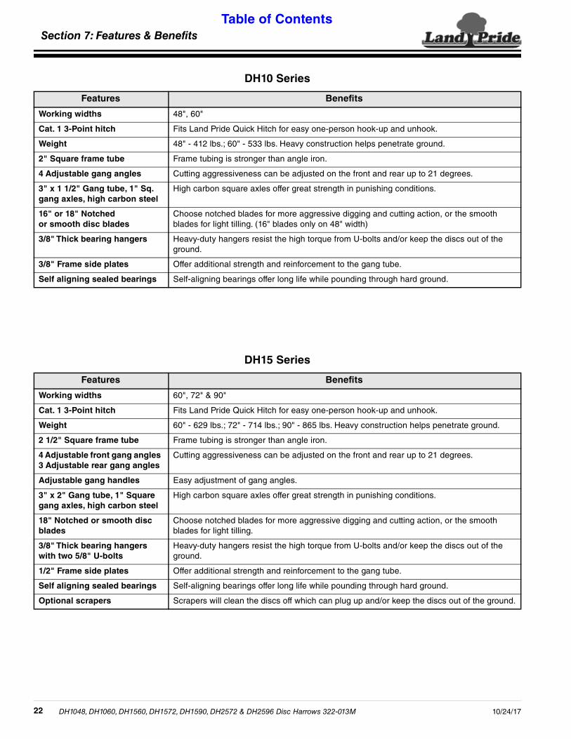
DH10 Series
Features Benefits
Working widths 48", 60"
Cat. 1 3-Point hitch Fits Land Pride Quick Hitch for easy one-person hook-up and unhook.
Weight 48" - 412 lbs.; 60" - 533 lbs. Heavy construction helps penetrate ground.
2" Square frame tube Frame tubing is stronger than angle iron.
4 Adjustable gang angles Cutting aggressiveness can be adjusted on the front and rear up to 21 degrees.
3" x 1 1/2" Gang tube, 1" Sq. gang axles, high carbon steel
High carbon square axles offer great strength in punishing conditions.
16" or 18" Notched or smooth disc blades
Choose notched blades for more aggressive digging and cutting action, or the smooth blades for light tilling. (16" blades only on 48" width)
3/8" Thick bearing hangers Heavy-duty hangers resist the high torque from U-bolts and/or keep the discs out of the ground.
3/8" Frame side plates Offer additional strength and reinforcement to the gang tube.
Self aligning sealed bearings Self-aligning bearings offer long life while pounding through hard ground.
DH15 Series
Features Benefits
Working widths 60", 72" & 90"
Cat. 1 3-Point hitch Fits Land Pride Quick Hitch for easy one-person hook-up and unhook.
Weight 60" - 629 lbs.; 72" - 714 lbs.; 90" - 865 lbs. Heavy construction helps penetrate ground.
2 1/2" Square frame tube Frame tubing is stronger than angle iron.
4 Adjustable front gang angles 3 Adjustable rear gang angles
Cutting aggressiveness can be adjusted on the front and rear up to 21 degrees.
Adjustable gang handles Easy adjustment of gang angles.
3" x 2" Gang tube, 1" Square gang axles, high carbon steel
High carbon square axles offer great strength in punishing conditions.
18" Notched or smooth disc blades
Choose notched blades for more aggressive digging and cutting action, or the smooth blades for light tilling.
3/8" Thick bearing hangers with two 5/8" U-bolts
Heavy-duty hangers resist the high torque from U-bolts and/or keep the discs out of the ground.
1/2" Frame side plates Offer additional strength and reinforcement to the gang tube.
Self aligning sealed bearings Self-aligning bearings offer long life while pounding through hard ground.
Optional scrapers Scrapers will clean the discs off which can plug up and/or keep the discs out of the ground.
DH1048, DH1060, DH1560, DH1572, DH1590, DH2572 & DH2596 Disc Harrows 322-013M 10/24/1722

Section 7: Features & BenefitsTable of Contents
DH25 SeriesFeatures Benefits
Working widths 72", 96"
Cat. 1 & 2 3-Point hitch Fits a wide variety of tractors.
Quick Hitch compatible Fits Land Prides Quick Hitch for easy one-person hook-up and unhook.
Weight 72" = 947 lbs.; 96" = 1143 lbs. Heavy construction helps penetrate ground
3" Square frame tube Heavy frame can handle 100 HP tractors.
Ball bearings Self-aligning, sealed ball bearings.
4 Adjustable front gang angles 3 Adjustable rear gang angles
Vary the degree of aggressiveness on both front and rear gangs up to 21 degrees.
Gang adjustment handle Easy adjustment of gang angles.
4" x 3" Gang tube The gang tube resists twisting due to 4" horizontal width.
1 1/8" Square gang axles Large axles can resist the high load put on them as the discs roll through the ground.
20" or 22" Notched disc blades
Larger discs will penetrate harder ground.
1/2" Thick bearing hangers 1/2" Thick bearing hangers resist high torque.
Optional scrapers Scrapers will clean the disc blades off which can plug up and/or keep the discs out of the ground due to mud build-up. Adjustable.
DH1048, DH1060, DH1560, DH1572, DH1590, DH2572 & DH2596 Disc Harrows 380-192M10/24/17 23

Section 8: TroubleshootingTable of Contents
Troubleshooting ChartProblem Cause Solution
Disc Harrow makes a high center ridge.
Disc blades are moving too much soil to the center.
Tilt Disc Harrow up at the rear by shortening the center 3-Point link. See “Disc Leveling Front To Rear” on page 15.
Decrease tractor speed.
Increase spacing between disc gangs by moving all gang hangers on both sides away from the center equal amounts.
Disc Harrow cuts a furrow (valley) in the center.
Disc blades are not moving enough soil to the center.
Tilt Disc Harrow down at the rear by lengthening the center 3-Point link.
Increase tractor speed.
Reduce spacing between rear disc gangs by moving all gang hangers on both sides toward the center by equal amounts.
Disc Harrow makes ridges on the out side cuts and furrows just inside the ridges.
Too much soil is thrown out by the front disc gangs.
Check front to rear disc leveling. Raise front disc gangs by lengthening the center 3-Point link.
Reduce front disc gang angle by one position.
Disc Harrow makes a furrow on the out side cuts and a ridge just inside the furrow.
Rear disc gangs are set too wide and picks up soil beyond where the front gangs throw it out.
Reduce spacing between rear disc gangs by moving all rear gang hangers in toward the center equal amounts.
Raise front disc gangs by lengthening the center 3-Point link.
Disc Harrow does not pull straight and/or shifts from side to side.
Front disc gangs run deeper than the rear disc gangs.
Tilt Disc Harrow down at the rear by lengthening the center 3-Point link.
Disc gangs are not centered on the frame. Center disc gangs on the Disc Harrow.
Front disc gangs not at the same angle. Set Front disc gangs at the same angle.
Rear disc gangs not at the same angle. Set Rear disc gangs at the same angle.
Disc Harrow leaves a depression in the worked soil behind tractor wheels
Tire slippage, heavy tractor, soft soil conditions.
Add duals, increase tractor speed, increase gang angle and/or increase cutting depth.
Tilt Disc Harrow down at the rear by lengthening the center 3-Point link.
Disc Harrow won’t settle down and operate smoothly.
Disc gang angles are set too high. Set disc gang angles at the smallest angle required to do the job. Make sure front disc gangs are set 3 degrees higher than the rear disc gang angles.
Disc Harrow does not penetrate soil properly.
Disc gangs are not set at enough angle. Increase disc gang angles. Make sure the front disc gangs are set 3 degrees more than the rear disc gangs.
Outside front disc blades and/or gang axle is bending or breaking.
Making sharp turns and crossing ditches with Disc Harrow in the ground.
Raise Disc Harrow out of the ground when making sharp turns and crossing ditches. Do Not cross deep ditches.
Gang axles become loose Keep disc gang axle nuts tight. See “Additional Torque Values” on page 26.
Section 8: Troubleshooting
DH1048, DH1060, DH1560, DH1572, DH1590, DH2572 & DH2596 Disc Harrows 322-013M 10/24/1724
Section 8: TroubleshootingTable of Contents
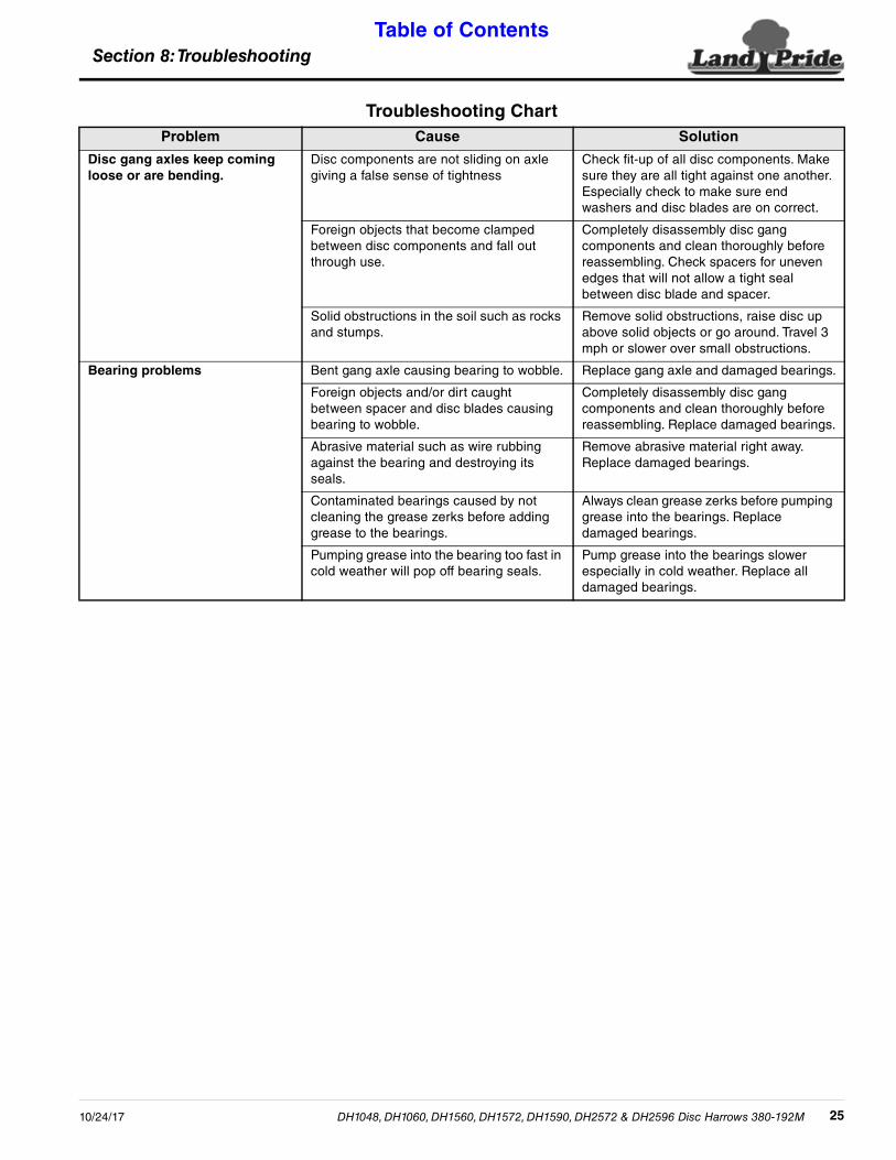
Disc gang axles keep coming loose or are bending.
Disc components are not sliding on axle giving a false sense of tightness
Check fit-up of all disc components. Make sure they are all tight against one another. Especially check to make sure end washers and disc blades are on correct.
Foreign objects that become clamped between disc components and fall out through use.
Completely disassembly disc gang components and clean thoroughly before reassembling. Check spacers for uneven edges that will not allow a tight seal between disc blade and spacer.
Solid obstructions in the soil such as rocks and stumps.
Remove solid obstructions, raise disc up above solid objects or go around. Travel 3 mph or slower over small obstructions.
Bearing problems Bent gang axle causing bearing to wobble. Replace gang axle and damaged bearings.
Foreign objects and/or dirt caught between spacer and disc blades causing bearing to wobble.
Completely disassembly disc gang components and clean thoroughly before reassembling. Replace damaged bearings.
Abrasive material such as wire rubbing against the bearing and destroying its seals.
Remove abrasive material right away. Replace damaged bearings.
Contaminated bearings caused by not cleaning the grease zerks before adding grease to the bearings.
Always clean grease zerks before pumping grease into the bearings. Replace damaged bearings.
Pumping grease into the bearing too fast in cold weather will pop off bearing seals.
Pump grease into the bearings slower especially in cold weather. Replace all damaged bearings.
Troubleshooting ChartProblem Cause Solution
DH1048, DH1060, DH1560, DH1572, DH1590, DH2572 & DH2596 Disc Harrows 380-192M10/24/17 25

Section 9: Torque Values ChartTable of Contents
Section 9: Torque Values Chart
DH1048, DH1060, DH1560, DH1572, DH1590, DH2572 & DH2596 Disc Harrows 322-013M 10/24/1726
Torque Values Chart for Common Bolt SizesBolt Head Identification Bolt Head Identification
Bolt Size (inches) Grade 2 Grade 5 Grade 8
Bolt Size(Metric) Class 5.8 Class 8.8 Class 10.9
in-tpi 1 N · m 2 ft-lb 3 N · m ft-lb N · m ft-lb mm x pitch 4 N · m ft-lb N · m ft-lb N · m ft-lb
1/4" - 20 7.4 5.6 11 8 16 12 M 5 X 0.8 4 3 6 5 9 7
1/4" - 28 8.5 6 13 10 18 14 M 6 X 1 7 5 11 8 15 11
5/16" - 18 15 11 24 17 33 25 M 8 X 1.25 17 12 26 19 36 27
5/16" - 24 17 13 26 19 37 27 M 8 X 1 18 13 28 21 39 29
3/8" - 16 27 20 42 31 59 44 M10 X 1.5 33 24 52 39 72 53
3/8" - 24 31 22 47 35 67 49 M10 X 0.75 39 29 61 45 85 62
7/16" - 14 43 32 67 49 95 70 M12 X 1.75 58 42 91 67 125 93
7/16" - 20 49 36 75 55 105 78 M12 X 1.5 60 44 95 70 130 97
1/2" - 13 66 49 105 76 145 105 M12 X 1 90 66 105 77 145 105
1/2" - 20 75 55 115 85 165 120 M14 X 2 92 68 145 105 200 150
9/16" - 12 95 70 150 110 210 155 M14 X 1.5 99 73 155 115 215 160
9/16" - 18 105 79 165 120 235 170 M16 X 2 145 105 225 165 315 230
5/8" - 11 130 97 205 150 285 210 M16 X 1.5 155 115 240 180 335 245
5/8" - 18 150 110 230 170 325 240 M18 X 2.5 195 145 310 230 405 300
3/4" - 10 235 170 360 265 510 375 M18 X 1.5 220 165 350 260 485 355
3/4" - 16 260 190 405 295 570 420 M20 X 2.5 280 205 440 325 610 450
7/8" - 9 225 165 585 430 820 605 M20 X 1.5 310 230 650 480 900 665
7/8" - 14 250 185 640 475 905 670 M24 X 3 480 355 760 560 1050 780
1" - 8 340 250 875 645 1230 910 M24 X 2 525 390 830 610 1150 845
1" - 12 370 275 955 705 1350 995 M30 X 3.5 960 705 1510 1120 2100 1550
1-1/8" - 7 480 355 1080 795 1750 1290 M30 X 2 1060 785 1680 1240 2320 1710
1-1/8" - 12 540 395 1210 890 1960 1440 M36 X 3.5 1730 1270 2650 1950 3660 2700
1-1/4" - 7 680 500 1520 1120 2460 1820 M36 X 2 1880 1380 2960 2190 4100 3220
1-1/4" - 12 750 555 1680 1240 2730 2010 1 in-tpi = nominal thread diameter in inches-threads per inch
1-3/8" - 6 890 655 1990 1470 3230 2380 2 N· m = newton-meters
1-3/8" - 12 1010 745 2270 1670 3680 2710 3 ft-lb= foot pounds
1-1/2" - 6 1180 870 2640 1950 4290 3160 4 mm x pitch = nominal thread diameter in millimeters x thread pitch1-1/2" - 12 1330 980 2970 2190 4820 3560
Torque tolerance + 0%, -15% of torquing values. Unless otherwise specified use torque values listed above.
Additional Torque ValuesDisc Gang Axle Nuts 1"-8 UNC 250 ft. lbs.
5.8 8.8 10.9
Section 10: WarrantyTable of Contents
Section 10: Warranty
DH1048, DH1060, DH1560, DH1572, DH1590, DH2572 & DH2596 Disc Harrows 380-192M10/24/17 27
WarrantyLand Pride warrants to the original purchaser that this Land Pride product will
be free from defects in material and workmanship beginning on the date ofpurchase by the end user according to the following schedule when used asintended and under normal service and conditions for personal use.
Overall Unit: One year Parts and Labor
Bearings: One year Parts and Labor
Discs: Discs are considered wear items
This Warranty is limited to the repair or replacement of any defective part byLand Pride and the installation by the dealer of any such replacement part, anddoes not cover common wear items such as blades, belts, tines, etc. Land Pridereserves the right to inspect any equipment or parts which are claimed to havebeen defective in material or workmanship.
This Warranty does not apply to any part or product which in Land Pride’sjudgment shall have been misused or damaged by accident or lack of normalmaintenance or care, or which has been repaired or altered in a way whichadversely affects its performance or reliability, or which has been used for apurpose for which the product is not designed. Misuse also specifically includesfailure to properly maintain oil levels, grease points, and driveline shafts.
Claims under this Warranty must be made to the dealer which originally soldthe product and all warranty adjustments must be made through such dealer. LandPride reserves the right to make changes in materials or design of the product atany time without notice.
This Warranty shall not be interpreted to render Land Pride liable for damagesof any kind, direct, consequential, or contingent to property. Furthermore, LandPride shall not be liable for damages resulting from any cause beyond itsreasonable control. This Warranty does not extend to loss of crops, any expenseor loss for labor, supplies, rental machinery or for any other reason.
No other warranty of any kind whatsoever, express or implied, is madewith respect to this sale; and all implied warranties of merchantability andfitness for a particular purpose which exceed the obligations set forth in thiswritten warranty are hereby disclaimed and excluded from this sale.
This Warranty is not valid unless registered with Land Pride within 30 days fromthe date of purchase.
IMPORTANT: The Online Warranty Registration should be completed by the dealer at the time of purchase. This information is necessary to provide you with quality customer service.
Model Number ____________________ Serial Number ____________________

Corporate Office: P.O. Box 5060Salina, Kansas 67402-5060 USA
www.landpride.com