disatac catalog - dantec dynamics...turbocharger turbocharger variants pickup/magnet pickup full...
TRANSCRIPT
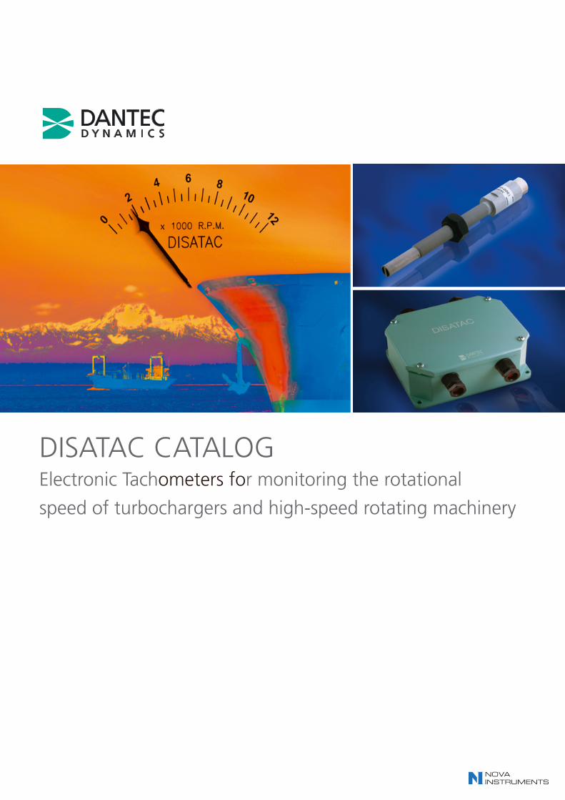
DISATAC CATALOGElectronic Tachometers for monitoring the rotational
speed of turbochargers and high-speed rotating machinery


CONTENTS
Introduction.................................................................... 4
DISATAC configuration guide.................................... 6
Product selection guidePickups and magnets ........................................................ 7Electronic units .................................................................. 7Meters................................................................................ 7Cables................................................................................ 7Special accessories .......................................................... 7Selection chart for pickups and magnets .......................... 8Selection chart for DISATAC electronic units .................. 10Connection options for DISATAC systems ...................... 11
Pickups and magnets in the 72C-series .............. 13
Pickups and magnets, 2-pole versionIntroduction...................................................................... 14Mounting.......................................................................... 14General specifications .................................................... 14Detailed specifications:
- Pickup types 72C03, 72C05 and 72C09.................. 15- Magnet types 72C31 and 72C35 ............................ 15
Pickups and magnets, 4-pole versionIntroduction...................................................................... 16Mounting.......................................................................... 16General specifications .................................................... 16 Detailed specifications:
- Pickup types 72C06, 72C08, 72C16 and 72C18 .... 17- Magnet types 72C21, 72C22, 72C23 and 72C24.... 17
Pickups in the 72K-series, multi-pole .................. 19Introduction...................................................................... 20Mounting.......................................................................... 20Specifications:
- Pickup types 72K01, 72K02, 72K05 and 72K06 ...... 20Mounting examples ........................................................ 21
Electronic units in the 72B-series .......................... 23General description ........................................................ 24Minimum speed of rotation .............................................. 24Maximum speed of rotation ............................................ 24Specifications:
- Electronic unit type 72B30........................................ 25- Electronic unit type 72B50........................................ 26 - Electronic unit type 72B60........................................ 27- Electronic unit type 72B61........................................ 28- Electronic unit type 72B62........................................ 29- Electronic unit type 72B63........................................ 30
Electronic units in the 72H-series .......................... 31General description ........................................................ 32Minimum speed of rotation .............................................. 32Specification .................................................................... 32
DISATAC meter DQ 96 .............................................. 35Description ...................................................................... 36General specifications .................................................... 36 Mounting specifications .................................................. 36
Cables, connectors and accessories .................... 37Cable types and cable length limitations ........................ 38Nomogram for calculating maximum length of cable ...... 39Detailed specifications .................................................... 40Junction Box .................................................................... 40Electronic limit switch ........................................................41
Service and Troubleshooting ............................ 44-45
Certificates.............................................................. 46-51
Ordering procedure & list of current DISATAC representativesOrdering procedure ........................................................ 52List of DISATAC representatives...................................... 52Ordering form .................................................................. 54
DISATAC - Electronic tachometers

4
DISATAC is a series of rugged, non-contact electronic tachometers that mon-itor rotational speed in all types of high-speed turbochargers and other kinds ofrotating machinery.
Only high-quality materials are usedin the manufacture of DISATAC tacho-meters to ensure optimal, reliable andlong-lasting performance in harsh work-ing environments. Except in 72H.. systems, the measurement principle isbased on a magnet mounted on a rotat-ing part inducing an alternating voltagein a DISATAC pickup placed a specificdistance from the magnet (or, in 72H..systems, another rotating part). As theequipment requires no mechanical con-nection to the rotating machine ele-ments, there is no mechanical wear.
The DISATAC electronic units con-vert the induced pickup voltage to ananalogue output current proportional tothe rotational speed. The electronic unitscan have built-in pointer instruments(meters). The alternative is an interfaceto an external meter, recorder, data-log-ger or equivalent. Meters indicating rota-tional speed can be placed several hundred metres from the pickup, e.g. onthe bridge of a large vessel.
All pickups and magnets are com-patible with the specifications of majorinternational turbocharger manufactur-ers.
DISATAC meets the ship-classifica-tion societies’ requirements for quality,reliability and safety and is thereforespecified as standard by most manufac-turers of large diesel engines and turbo-chargers in the marine and off-shoreindustries.
Introduction to DISATAC

72B DISATAC systemsThe rotating magnet mounted on theshaft of the turbocharger induces analternating voltage in the pickup. Theelectronic unit converts the signal to acurrent proportional to the rotationalspeed. The output is able to drive one ormore meters, dataloggers or recordersand a current loop, depending on themodel. 72 B-series does not requireexternal power supply.
72H DISATAC systemsThe pickup senses the induction frome.g. a gearwheel and the electronic unitconverts the signal to a current propor-tional to the rotating speed. The 72Hsystems can also be used with 72C pick-ups/magnets. The 72H systems requirean external power supply.
Introduction to DISATAC
5
6
9140K0012(Specify length)
9006A1661 (2 m)
9006A1660(Specify length)
9072K1431 (2 m)
9072K1430(Specify length)
9140K0012(Specify length)
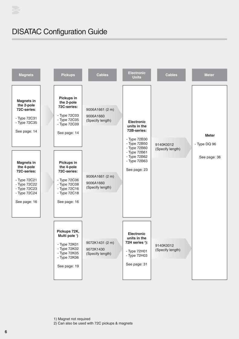
DISATAC Configuration Guide
Magnets inthe 2-pole
72C-series:
- Type 72C31- Type 72C35
See page: 14
Pickups inthe 2-pole
72C-series:
- Type 72C03- Type 72C05- Type 72C09
See page: 14Meter
- Type DQ 96
See page: 36
Pickups inthe 4-pole
72C-series:
- Type 72C06- Type 72C08- Type 72C16- Type 72C18
See page: 16
Magnets inthe 4-pole
72C-series:
- Type 72C21- Type 72C22- Type 72C23- Type 72C24
See page: 16
Pickups 72K, Multi pole 1)
- Type 72K01- Type 72K02- Type 72K05- Type 72K06
See page: 19
1) Magnet not required2) Can also be used with 72C pickups & magnets
Electronicunits in the
72H series 2):
- Type 72H01 - Type 72H03
See page: 31
Electronicunits in the72B-series:
- Type 72B30 - Type 72B50 - Type 72B60- Type 72B61- Type 72B62- Type 72B63
See page: 23
9006A1661 (2 m)
9006A1660(Specify length)
Magnets Pickups Cables Cables MeterElectronicUnits

Selecting pickup and magnetThere are two series of DISATAC pick-ups.
• The 72C-series, with two types of pickup/magnet: 2-pole and 4-pole. These pickups and their correspond-ing magnets are for use with both the72B-series and 72H01 DISATAC electronic units.
• The 72K-series. These pickups can only be used with the 72H01 or 72H03 DISATAC electronic units. They do not require a rotating mag-net, but are simply positioned next to any gear-wheel, perforated disk, shaft with bosses or equivalent. The rotating part must be of ferrous mate-rial, so that a signal is generated.
The type of pickup to select depends onthe application and type of equipment.The DISATAC range of pickups and mag-nets are compatible with a large range ofturbochargers, as shown in thepickup/magnet selection chart on page 8.
Detailed specifications of pickups and magnets are provided on page 13-21.
Selecting an electronic unitThere are two electronic unit systems inthe DISATAC programme: the 72B-series and the 72H-series. Theircompatibility with different pickups isshown in the selection chart “DISATACelectronic units” on page 10 and the con-figuration guide on page 6.
IMPORTANT: If you order a replacementunit, please indicate the code numbershown on your present electronic unit.
Every DISATAC electronic unit is individually calibrated to the customer’s specifications before shipment and is marked with a calibration number,9072B... (or 72B...), both on the outsideof the box and on the electronic chassis.
Detailed specifications of electronic unitsare provided on page 23-34.
Selecting a DISATAC meterDISATAC meters are all manufacturedfor use with the other DISATAC ele-ments. Any DISATAC meter can be usedin any DISATAC system. When orderinga meter please specify:
• Type number of the meter.
• Full-scale RPM reading.
• Special requests for meter markings (e.g. a red-coloured section).
(NB: If the meter type is not specified,the DQ 96 type is delivered as stan-dard.)
Detailed specifications of DISATACmeters are provided on page 35-36.
Selecting cablesThe standard cable length supplied is 2metres. If longer cables are required,please specify the length on the orderform. The DISATAC configuration guideon page 6 shows the cables to select forthe connections between pickups andelectronic units, and electronic units andmeters.
Detailed specifications of cables and connectors are provided on page 37-41.
Special accessoriesA number of accessories for DISATAC systems are available, e.g.:
• Pickup cable connectors
• Junction box for pickup cables
• Coaxial pickup connector for 72B30 and 72B60-63 electronic units
• Electronic limit switch with 2 set-points and isolated relay outputs
• Selector switches; 2-, 4- or 8-channels
• Disatac selector switch - 2, 4 or 8 input channels
Please contact Dantec Dynamics A/S forfurther information about special acces-sories.
How to order DISATAC products are available on oureshop - http://shop.dantecdynamics.com/
7
Product selection guide

8
Turbocharger Turbocharger Variants Pickup/magnet Pickup Full scalesupplier type 72B system 72H system RPM
ABB TPL 73 TPL/TPS turbochargers are not applicable To be connected 30,000(BBC) TPL 77 delivered from ABB with pickup not applicable without the special 25,000
Switzerland TPL 80 built in (2 pulses per rev.) not applicable ABB pickup 20,000TPL 85 not applicable amplifier! 17,500
VTR160 WE*), WF 72C06 / 72C22 50,000WE*), WP (until Feb. 1975) 72K01WE*), WP (from Mar. 1975) 72K02
VTR161 WP 72K02 50,000
VTR184-6-001 72K06 55,000
VTR200 WE*) 72C06 / 72C25**) 40,000WE*), WP (until Aug. 1974) 72K01WE*), WP (from Sep. 1974) 72K02
VTR201 WP 72K02 40,000
VTC214 72K06 40,000
VTC214-6-001 72K06 45,000
VTR214 72K02 40,000
VTR214-6-001 72K06 45,000
VTR250 WE*), WF 72C06 / 72C22 30,000WE*), WP (until Dec. 1969) 72K01WE*), WP (from Jan. 1970) 72K02
VTR251 WP 72K02 30,000
VTC254 72K02 40,000
VTC254-6-001 72K02 40,000
VTR254 72K02 40,000
VTR254-6-001 72K02 40,000
VTC304 72K06 35,000
VTC304-6-001 72K02 30,000
VTR304 72K02 30,000
VTR304-6-001 PE1, LS1 72K06 30,000PE2, LS2 72C18 / 72C21
VTR320 WE*), GF 72C06 / 72C23 25,000WF (until Jul. 1976) 72C06 / 72C23G2F,WF (from Aug. 1976) 72C08 / 72C23WE*), WP (until Jun. 1974) 72K01WE*), WP (from Jul. 1974) 72K02
VTR321 WP 72K02 25,000
VTR354 72K02 30,000
VTR354-6-001 PE1, LS1 72K06 30,000PE2, LS2 72C18 / 72C21
VTR400 WE, WZ, WF, GF (until Jul. 1976) 72C06 / 72C21 20,000WE, WF, G2F (from Aug. 1976) 72C08 / 72C21
VTR401 WZ, WF, G2F 72C08 / 72C21 20,000
VTR454 72C08 / 72C21 20,000
VTR454-6-001 72C18 / 72C21 25,000
VTR500 WE, WZ, WF, GF, GF1 72C06 / 72C21 16,000(until July 1976)WZ, WZ6, WF, G2F 72C08 / 72C21(from Aug. 1976)
VTR501 WZ, WZ5, WZ6, WF, G2F 72C08 / 72C21 16,000
VTR564 72C08 / 72C21 16,000
VTR564-6-001 72C18 / 72C21 18,000
VTR630 WE, WZ, WF*), GF, GF1 72C06 / 72C22 12,000WF*), G2F 72C08 / 72C22
VTR630-6-001 72C18 / 72C21 18,000
VTR631 WE, WZ, WZ5, WF*), GF1 72C06 / 72C22 12,000WF*), G2F 72C08 / 72C22
VTR714 72C08 / 72C22 12,000
VTR714-6-001 72C18 / 72C22 15,000
Selection chart for pickup and magnet
*) Please check with ABB documentation **) Discontinued. Please contact Dantec Dynamics for availability.

9
Turbocharger Turbocharger Variants Pickup/magnet Pickup Full scalesupplier type 72B system 72H system RPM
ABB VTR750 WE, WZ, WF*), GF 72C06 / 72C22 10,000(BCC) WZ5, WZ6, WF*), G2F 72C08 / 72C22
continued
VTR751 WZ 72C06 / 72C22 10,000WZ5, WZ6, WF, G2F 72C08 / 72C22
VTR900 GF 72C08 / 72C26**) 9,000
RATEAU GTS50 72C06 / 72C22 11,000France GTS58 72C06 / 72C22 10,000
GTS67.5 72C06 / 72C22 8,000GTS258 72C06 / 72C22 9,000GTS268 72C06 / 72C22 10,000
Gebr. SULZER TCA85 72C06 / 72C22 9,000Switzerland RT67 / TC75 72C06 / 72C22 12,000
RT56 / TC60 72C06 / 72C22 15,000RT45 / TC45 72C06 / 72C22 20,000
BURMEISTER T330G, T330GB 72K02 18,000& WAIN T440G, T440GB 72K02 16,000Denmark T540G 72C06 / 72C24 15,000
T550GB 72C06 / 72C24 14,000T680G 72C06 / 72C24 12,000T780G 72C06 / 72C24 10,000T1080F/G 72C06 / 72C24 8,000
ELSINORE TH5 72C06 / 72C22 25,000SHIPYARD TH10 72C06 / 72C22 21,000Denmark TH13 72C06 / 72C22 21,000
TH20 72C06 / 72C22 17,000TH22 72C06 / 72C22 17,000TH23 72C06 / 72C22 17,000TH40 72C06 / 72C22 14,000TH44 72C06 / 72C22 14,000TH45 72C06 / 72C22 14,000TH46 72C06 / 72C22 14,000
MAN NR 20 DISATAC 72B.. series and 45,000Germany NR 24 72H01 electronic units are 40,000
NR 26 compatible with MAN turbo- 35,000(Turbochargers NA 34 chargers with built-in 30,000
are delivered with NA 40 pickup/magnet. Output from 25,000pickup and NA 48 this pickup corresponds to 20,000
magnet built in.) NA 57 the output from a DISATAC 18,000NA 70 72C.. 2-pole pickup. 15,000NA 83 12,000
NAPIER HP.100 72C03 / 72C34 *) 30,000England MS.100 72C03 / 72C34 *) 25,000
HP.200 72C03 / 72C35 25,000MS.200 72C03 / 72C35 20,000HP.210 72C03 / 72C35 25,000MS.210 72C03 / 72C35 20,000HP.400 72C06 / 72C22 15,000MS.400 72C06 / 72C22 12,000410A 72C06 / 72C22 14,000HP.500 72C06 / 72C22 12,000MS.500 72C06 / 72C22 10,000510A 72C06 / 72C22 12,000HP.600 72C06 / 72C22 9,000MS.600 72C06 / 72C22 8,000610A 72C06 / 72C22 9,000NA450 72K02 18,000NA550 Mk. 1R 72C06 / 72C22 14,000NA550 Mk. 2 72C06 / 72C22 15,000NA650 72C06 / 72C22 12,000NA455 72K02 20,000NA555 72K02 15,000NA655 72C08 / 72C22 12,000S410B 72C06 / 72C22 18,000S510B 72C06 / 72C22 12,000S610B 72C06 / 72C22 12,000
Selection chart for pickup and magnet
* Discontinued. Please contact Dantec Dynamics for availability
10
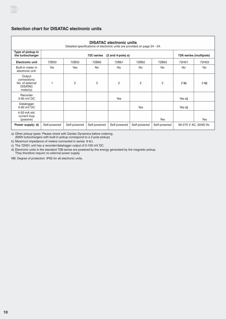
DISATAC electronic unitsDetailed specifications of electronic units are provided on page 24 - 34.
Type of pickup in the turbocharger 72C-series (2 and 4-pole) a) 72K-series (multipole)
Electronic unit 72B30 72B50 72B60 72B61 72B62 72B63 72H01 72H03
Built-in meter in No Yes No No No No No Noelectronic unit:
Output connections:
No. of external 1 2 3 2 2 2 2 b) 2 b)DISATACmeter(s)
Recorder0-90 mV DC Yes Yes c)
Datalogger0-90 mV DC Yes Yes c)
4-20 mA std.current loop
(passive) Yes Yes
Power supply: d) Self-powered Self-powered Self-powered Self-powered Self-powered Self-powered 90-270 V AC, 50/60 Hz
a) Other pickup types: Please check with Dantec Dynamics before ordering. (MAN turbochargers with built-in pickup correspond to a 2-pole pickup)
b) Maximum impedance of meters connected in series: 9 kΩ.c) The 72H01 unit has a recorder/datalogger output of 0-100 mV DC.d) Electronic units in the standard 72B-series are powered by the energy generated by the magnetic pickup.
They therefore require no external power supply.
NB: Degree of protection: IP65 for all electronic units.
Selection chart for DISATAC electronic units

11
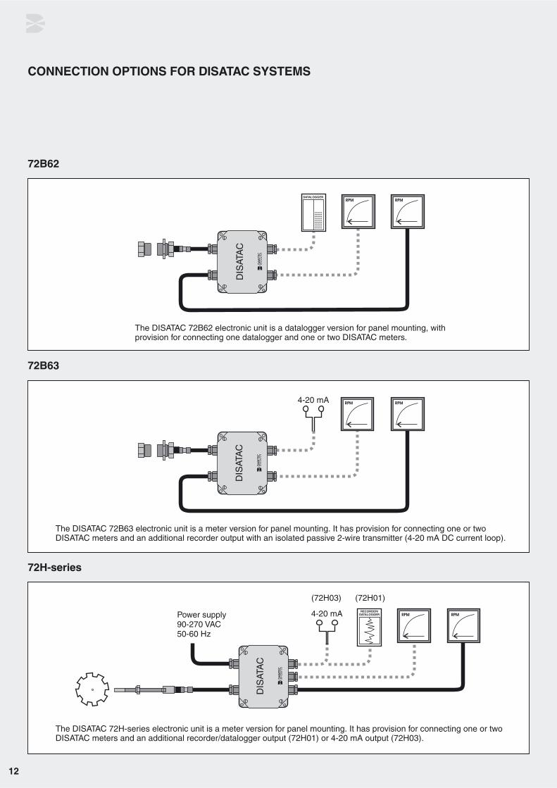
CONNECTION OPTIONS FOR DISATAC SYSTEMS
72B30
72B60
72B61
72B50
The DISATAC 72B30 electronic unit has facilities forconnecting one DISATAC meter.
The DISATAC 72B50 electronic unit has a built-in pointerinstrument (meter) as well as facilities for connectingone or two additional DISATAC meters.
The DISATAC 72B60 electronic unit is designed for panel mounting.It has provision for connecting one, two or three DISATAC meters.
The DISATAC 72B61 electronic unit is a recorder version for panel mounting,with provision for connecting one recorder and one or two DISATAC meters.
12
CONNECTION OPTIONS FOR DISATAC SYSTEMS
72B62
72B63
72H-series
The DISATAC 72B62 electronic unit is a datalogger version for panel mounting, withprovision for connecting one datalogger and one or two DISATAC meters.
The DISATAC 72B63 electronic unit is a meter version for panel mounting. It has provision for connecting one or two DISATAC meters and an additional recorder output with an isolated passive 2-wire transmitter (4-20 mA DC current loop).
The DISATAC 72H-series electronic unit is a meter version for panel mounting. It has provision for connecting one or two DISATAC meters and an additional recorder/datalogger output (72H01) or 4-20 mA output (72H03).

Pickups and magnets in the 72C-series
14
IntroductionThe DISATAC 72C-series pickup pro-gramme comprises pickups with magnets, for use with the 72B- and 72H-series DISATAC electronic units. The72C-series includes two types of pick-ups/magnets - 2-pole and 4-pole.
DISATAC 72C-series pickups and magnets meet the specifications ofLloyd’s Register of Shipping-Test Spec-ifications 1 (1996) - ENV4.
Pickups and magnets: 2-pole versionsAny magnet in this group can be com-bined with any 2-pole pickup.
A wide range of turbochargers isprepared for use with DISATAC. Thetype of pickup and magnet required de-pend on the application and type ofturbocharger.
(Please refer to selection chart for pick-ups and magnets on page 8).
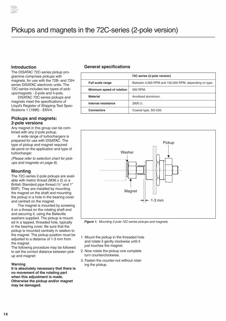
MountingThe 72C-series 2-pole pickups are avail-able with metric thread (M36 x 2) or aBritish Standard pipe thread (½” and 1”BSP). They are installed by mountingthe magnet on the shaft and mountingthe pickup in a hole in the bearing coverand centred on the magnet.
The magnet is mounted by screwingit on a thread on the rotating shaft endand securing it, using the Bellevillewashers supplied. The pickup is mount-ed in a tapped, threaded hole, typicallyin the bearing cover. Be sure that thepickup is mounted centrally in relation tothe magnet. The pickup position must beadjusted to a distance of 1-3 mm fromthe magnet.The following procedure may be followedto set the correct distance between pick-up and magnet:
WarningIt is absolutely necessary that there isno movement of the rotating partwhen this adjustment is made. Otherwise the pickup and/or magnetmay be damaged.
Pickups and magnets in the 72C-series (2-pole version)
72C-series (2-pole version)
Full scale range Between 4,000 RPM and 100,000 RPM, depending on type.
Minimum speed of rotation 500 RPM.
Material Anodised aluminium.
Internal resistance 2800 Ω.
Connectors Coaxial type, SO-239.
General specifications
Figure 1. Mounting 2-pole 72C-series pickups and magnets.
1. Mount the pickup in the threaded hole and rotate it gently clockwise until it just touches the magnet.
2. Now rotate the pickup one complete turn counterclockwise.
3. Fasten the counter-nut without rotat-ing the pickup.

15
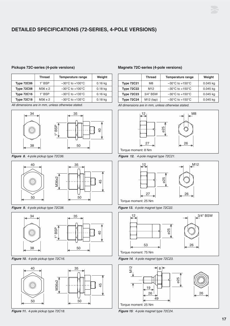
Thread Temperature range Weight
Type 72C03 ½’’ BSP –30°C to +100°C 0.06 kg
Type 72C05 1” BSP –30°C to +100°C 0.14 kg
Type 72C09 M36 x 2 –30°C to +100°C 0.16 kg
DETAILED SPECIFICATIONS (72C-SERIES, 2-POLE VERSIONS)
Pickups 72C-series (2-pole versions)
Figure 2. 2-pole pickup type 72C03.
All dimensions are in mm, unless otherwise stated.
All dimensions are in mm, unless otherwise stated.
Figure 3. 2-pole pickup type 72C05.
Figure 4. 2-pole pickup type 72C09.
Figure 5. 2-pole magnet type 72C31.
Torque moment: 8 Nm
Torque moment: 75 Nm
Figure 6. 2-pole magnet type 72C35.
Thread Temperature range Weight
Type 72C31 M8 –30°C to +150°C 0.01 kg
Type 72C35 11/16” x 1/14” –30°C to +150°C 0.01 kg
Magnets 72C-series (2-pole versions)
16
IntroductionThe DISATAC 72C-series pickup pro-gramme comprises pickups with magnets for use with the 72B- and 72H-series DISATAC electronic units. The72C-series includes two types of pick-ups/magnets - 2-pole and 4-pole.
DISATAC 72C-series of pickups andmagnets meets the specifications ofLloyd’s Register of Shipping-Test Spec-ifications 1 (1996) - ENV4.
Pickups and magnets:4-pole versionsThe 4-pole pickups consist of two types - one designed for normal temperatures (-30°C to +100°C) and one for the high-temperature range (-30°C to +135°C).Any magnet in this group can be com-bined with any 4-pole DISATAC pickup.A wide range of turbochargers is pre-pared for use with DISATAC. The type ofpickup and magnet required depend onthe application and type of turbocharger.
(Please refer to selection chart for pick-ups and magnets on page 8).
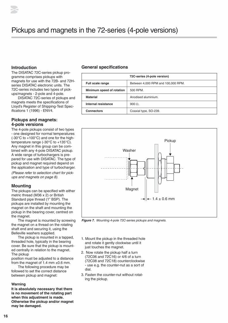
MountingThe pickups can be specified with eithermetric thread (M36 x 2) or BritishStandard pipe thread (1” BSP). Thepickups are installed by mounting themagnet on the shaft and mounting thepickup in the bearing cover, centred onthe magnet.
The magnet is mounted by screwingthe magnet on a thread on the rotatingshaft end and securing it, using theBelleville washers supplied.
The pickup is mounted in a tapped,threaded hole, typically in the bearingcover. Be sure that the pickup is mount-ed centrally in relation to the magnet.The pickup position must be adjusted to a distancefrom the magnet of 1.4 mm ±0.6 mm.
The following procedure may be followed to set the correct distancebetween pickup and magnet:
WarningIt is absolutely necessary that thereis no movement of the rotating partwhen this adjustment is made.Otherwise the pickup and/or magnetmay be damaged.
Pickups and magnets in the 72-series (4-pole versions)
72C-series (4-pole version)
Full scale range Between 4,000 RPM and 100,000 RPM.
Minimum speed of rotation 500 RPM.
Material Anodised aluminium.
Internal resistance 900 Ω.
Connectors Coaxial type, SO-239.
General specifications
Figure 7. Mounting 4-pole 72C-series pickups and magnets.
1. Mount the pickup in the threaded holeand rotate it gently clockwise until it just touches the magnet.
2. Now rotate the pickup half a turn (72C06 and 72C16) or 4/6 of a turn (72C08 and 72C18) counterclockwise- use e.g. the counter-nut as a sort of dial.
3. Fasten the counter-nut without rotat-ing the pickup.
17
Thread Temperature range Weight
Type 72C06 1” BSP –30°C to +100°C 0.16 kg
Type 72C08 M36 x 2 –30°C to +100°C 0.18 kg
Type 72C16 1” BSP –30°C to +135°C 0.16 kg
Type 72C18 M36 x 2 –30°C to +135°C 0.18 kg
DETAILED SPECIFICATIONS (72-SERIES, 4-POLE VERSIONS)
Pickups 72C-series (4-pole versions)
Figure 8. 4-pole pickup type 72C06.
All dimensions are in mm, unless otherwise stated.
Thread Temperature range Weight
Type 72C21 M8 –30°C to +150°C 0.045 kg
Type 72C22 M12 –30°C to +150°C 0.045 kg
Type 72C23 3/4” BSW –30°C to +150°C 0.045 kg
Type 72C24 M12 (tap) –30°C to +150°C 0.045 kg
All dimensions are in mm, unless otherwise stated.
Figure 9. 4-pole pickup type 72C08.
Figure 10. 4-pole pickup type 72C16. Figure 14. 4-pole magnet type 72C23.
Figure 15: 4-pole magnet type 72C24.Figure 11. 4-pole pickup type 72C18.
Figure 12. 4-pole magnet type 72C21.
Figure 13. 4-pole magnet type 72C22.
Magnets 72C-series (4-pole versions)
Torque moment: 8 Nm
Torque moment: 25 Nm
Torque moment: 75 Nm
Torque moment: 25 Nm

18
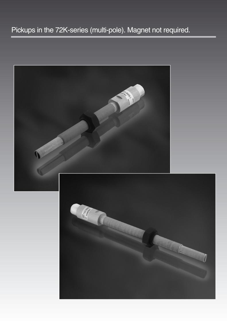
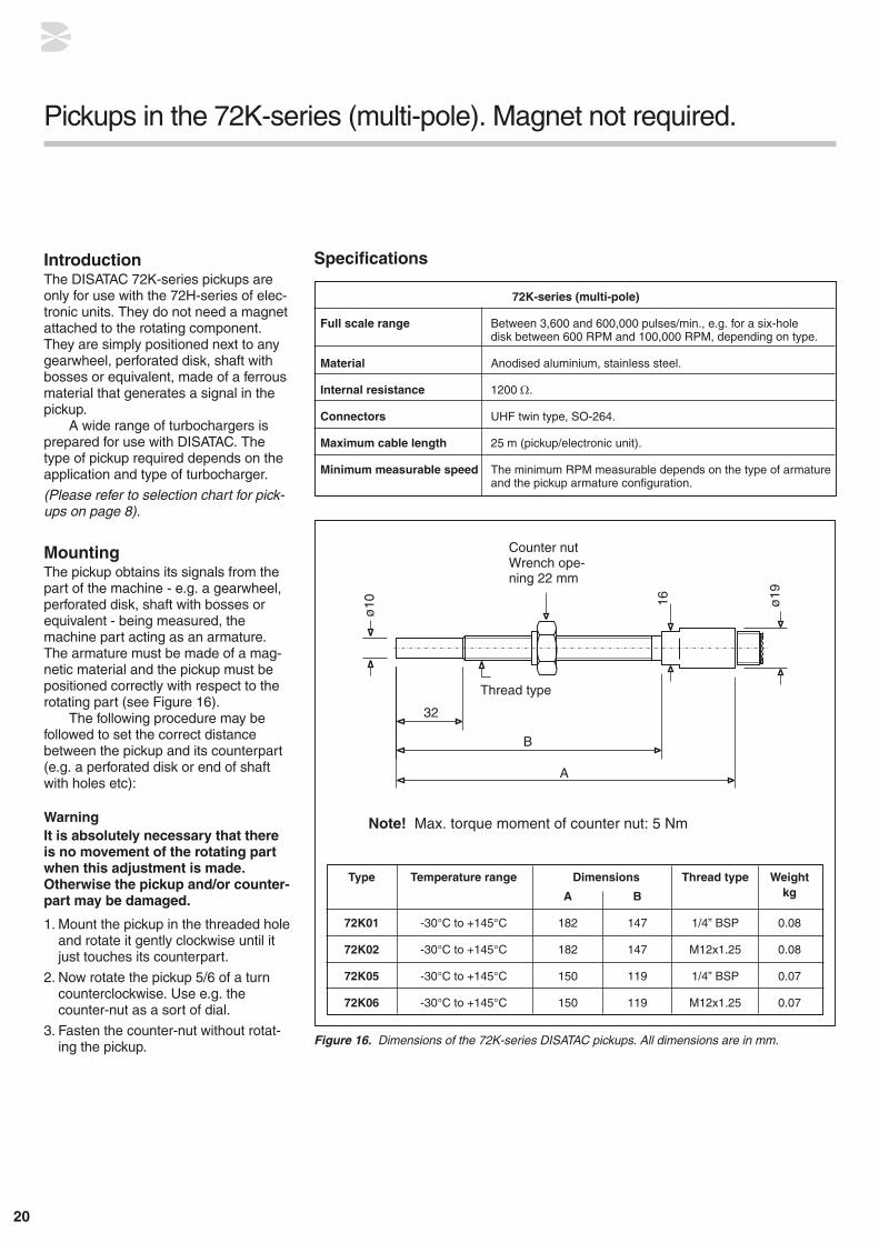
Pickups in the 72K-series (multi-pole). Magnet not required.
20
IntroductionThe DISATAC 72K-series pickups areonly for use with the 72H-series of elec-tronic units. They do not need a magnetattached to the rotating component.They are simply positioned next to anygearwheel, perforated disk, shaft withbosses or equivalent, made of a ferrousmaterial that generates a signal in thepickup.
A wide range of turbochargers is prepared for use with DISATAC. Thetype of pickup required depends on theapplication and type of turbocharger.
(Please refer to selection chart for pick-ups on page 8).
MountingThe pickup obtains its signals from thepart of the machine - e.g. a gearwheel,perforated disk, shaft with bosses orequivalent - being measured, themachine part acting as an armature.The armature must be made of a mag-netic material and the pickup must bepositioned correctly with respect to the rotating part (see Figure 16).
The following procedure may be followed to set the correct distancebetween the pickup and its counterpart(e.g. a perforated disk or end of shaftwith holes etc):
WarningIt is absolutely necessary that thereis no movement of the rotating partwhen this adjustment is made.Otherwise the pickup and/or counter-part may be damaged.
1. Mount the pickup in the threaded hole and rotate it gently clockwise until it just touches its counterpart.
2. Now rotate the pickup 5/6 of a turncounterclockwise. Use e.g. the counter-nut as a sort of dial.
3. Fasten the counter-nut without rotat-ing the pickup.
Pickups in the 72K-series (multi-pole). Magnet not required.
Figure 16. Dimensions of the 72K-series DISATAC pickups. All dimensions are in mm.
72K-series (multi-pole)
Full scale range Between 3,600 and 600,000 pulses/min., e.g. for a six-hole disk between 600 RPM and 100,000 RPM, depending on type.
Material Anodised aluminium, stainless steel.
Internal resistance 1200 Ω.
Connectors UHF twin type, SO-264.
Maximum cable length 25 m (pickup/electronic unit).
Minimum measurable speed The minimum RPM measurable depends on the type of armature and the pickup armature configuration.
Specifications
Type Temperature range Dimensions Thread type Weight
A B kg
72K01 -30°C to +145°C 182 147 1/4” BSP 0.08
72K02 -30°C to +145°C 182 147 M12x1.25 0.08
72K05 -30°C to +145°C 150 119 1/4” BSP 0.07
72K06 -30°C to +145°C 150 119 M12x1.25 0.07
Note! Max. torque moment of counter nut: 5 Nm

21
MOUNTING EXAMPLES
Coaxial positioning
A rod-end with two 4 mmdia. holes 2 mm deep on a6.6 mm dia. circle.E.g. placed in a screwhead.
72K.. pickup mountedcoaxially with the rotating axis
Eccentric positioning
Figure 17. Coaxial positioning of 72K-series DISATAC pickup.
Figure 18. Eccentric positioning of 72K-series DISATAC pickup.
An 8 mm iron plate with six 5 mm dia. holes on a 66 mm dia. circle.
72K.. pickup mounted33 mm off axis with respectto the rotation axis

22
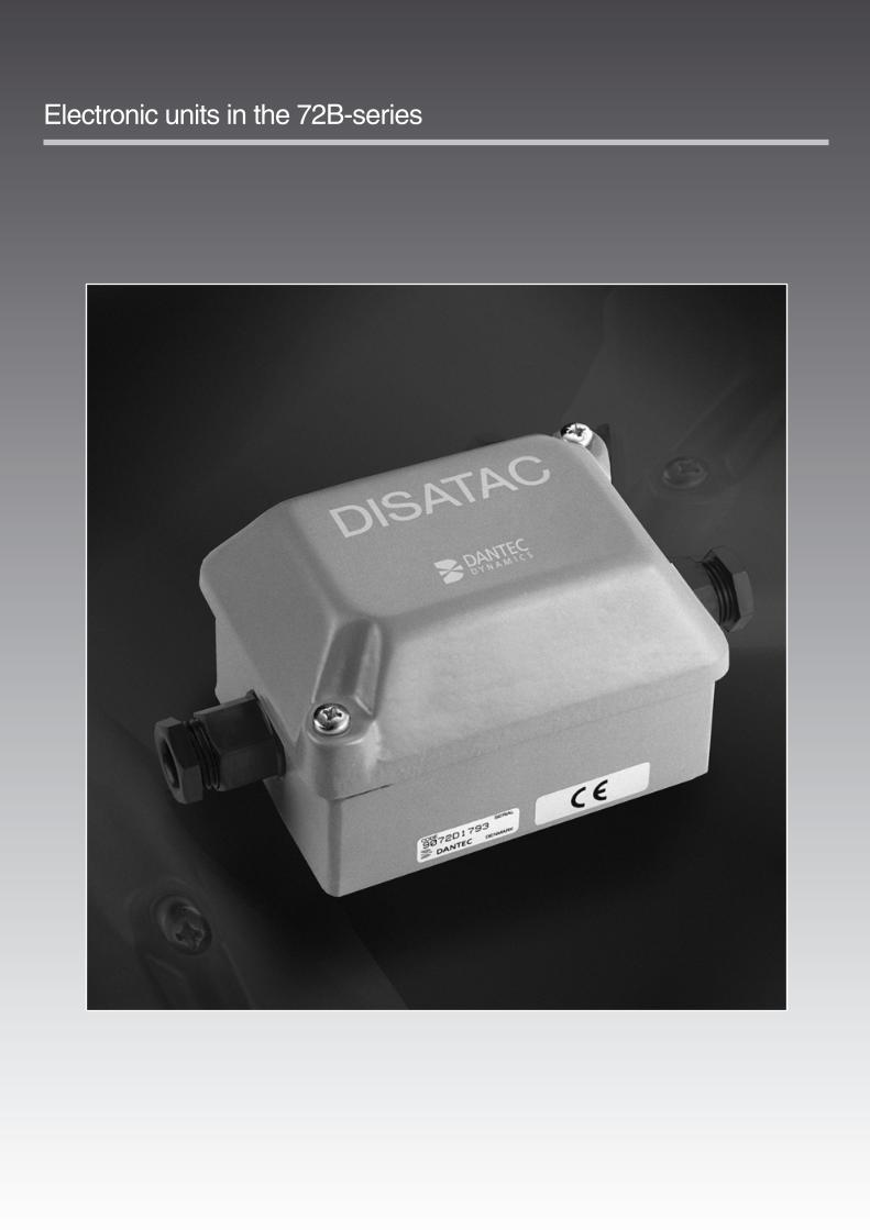
Electronic units in the 72B-series

24
General descriptionDISATAC electronic tachometers arerugged and reliable systems for contact-less measurement of the rotationalspeed of any kind of rotating machinery.They offer significant advantages in themeasurement of high rotational speeds.
The DISATAC system consists ofone or more magnets, a pickup placed aspecified distance from the magnet, andan electronic unit. Since it requires nomechanical connection to the rotatingmachine element, there is no mechani-cal wear. The magnet, which is mountedon the rotating part, induces an alternat-ing voltage in a stationary DISATACpickup. This voltage is converted in theDISATAC electronic unit to a DC outputcurrent proportional to the rotationalspeed.
The standard DISATAC model is powered by the energy generated by themagnetic pickup and thus requires no external power supply.
Minimum speed of rotationThe working range of the DISATAC hasa lower limit. If the speed of rotation decreases beyond a certain point, the induced working voltage will be inade-quate. This causes an error in the meterreading, as illustrated by Figure 19.The minimum speed of rotation defined
above is listed for each pickup in thechapter on pickups and magnets. At lowspeeds of rotation, the pointer mayvibrate because of the relatively longinterval between the charging pulses.
Maximum speed of rotationDantec should be consulted concerningthe use of specially DISATAC 72C-series pickups above 100,000 RPM. Suchspeeds may result in problems regardingthe mechanical strength of themagnet(s) and mechanical stress thatmay be imposed by the magnet on therotating machinery.
Coaxial connector in pickup inputIf requested, all 72B-series electronicunits can be delivered in a modified version in which the pickup cable entry(gland) is replaced by a female coaxialconnector (SO-239).
This modification has part number9072D2991.
Calibration code numberEvery DISATAC electronic unit is individually calibrated to the customer’s specifications before shipment and ismarked with a calibration number,9072B... (or 72B...), both on the outsideof the box and on the electronic chassis.
This calibration number both identi-fies the type of DISATAC unit and the calibration data. It should always bequoted in connection with queries.
Electronic units in the 72B-series
Figure 19. Meter reading error at low rotation-al speed, caused by inadequate induced work-ing voltage.
Serial number
Calibrated for 12,000 RPMfull scale (300 µA output)
Type of pickup/magnet
2p : 2-pole pickup/magnet4p : 4-pole pickup/magnet
Calibration code number
25
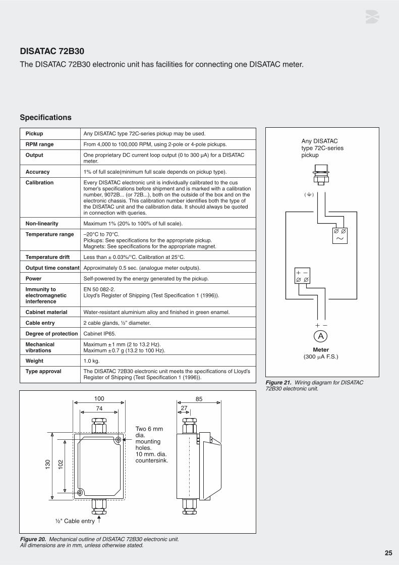
Figure 21. Wiring diagram for DISATAC72B30 electronic unit.
Figure 20. Mechanical outline of DISATAC 72B30 electronic unit. All dimensions are in mm, unless otherwise stated.
Pickup Any DISATAC type 72C-series pickup may be used.
RPM range From 4,000 to 100,000 RPM, using 2-pole or 4-pole pickups.
Output One proprietary DC current loop output (0 to 300 µA) for a DISATAC meter.
Accuracy 1% of full scale(minimum full scale depends on pickup type).
Calibration Every DISATAC electronic unit is individually calibrated to the customer’s specifications before shipment and is marked with a calibrationnumber, 9072B... (or 72B...), both on the outside of the box and on the electronic chassis. This calibration number identifies both the type of the DISATAC unit and the calibration data. It should always be quoted in connection with queries.
Non-linearity Maximum 1% (20% to 100% of full scale).
Temperature range –20°C to 70°C.Pickups: See specifications for the appropriate pickup. Magnets: See specifications for the appropriate magnet.
Temperature drift Less than ± 0.03%/°C. Calibration at 25°C.
Output time constant Approximately 0.5 sec. (analogue meter outputs).
Power Self-powered by the energy generated by the pickup.
Immunity to EN 50 082-2.electromagnetic Lloyd’s Register of Shipping (Test Specification 1 (1996)).interference
Cabinet material Water-resistant aluminium alloy and finished in green enamel.
Cable entry 2 cable glands, ½” diameter.
Degree of protection Cabinet IP65.
Mechanical Maximum ±1 mm (2 to 13.2 Hz). vibrations Maximum ±0.7 g (13.2 to 100 Hz).
Weight 1.0 kg.
Type approval The DISATAC 72B30 electronic unit meets the specifications of Lloyd’sRegister of Shipping (Test Specification 1 (1996)).
Specifications
DISATAC 72B30The DISATAC 72B30 electronic unit has facilities for connecting one DISATAC meter.

26
Figure 22. Mechanical outline of DISATAC 72B50 electronic unit. All dimensions are in mm,unless otherwise stated.
Figure 23. Wiring diagram for DISATAC72B50 electronic unit.
ConnectionsRemove the resistor(s) before connect-ing the DISATAC meter(s).
The resistor(s) must be installedagain when disconnecting the DISATACmeter(s).
Pickup Any DISATAC type 72C-series pickup may be used.
RPM range From 4,000 to 100,000 RPM using 2-pole or 4-pole pickups.
Meter A DS 120A meter is built in the cabinet.
Output One or two proprietary DC current loop outputs (0 to 300 µA) for DISATAC analogue meters.
Accuracy 1% of full scale (min. full scale depends on pickup type)
Calibration Every DISATAC electronic unit is individually calibrated to the customer’s specifications before shipment and marked with a calibration number, 9072B.... (or 72B....), both on the outside of the box and on the electronic chassis. This calibration number identifies both the type of the DISATAC unit and the calibration data. It should always be quoted in connection with queries.
Non-linearity Maximum 1% (20% to 100% of full scale).
Temperature range –20°C to 70°C.Pickups: See specifications for the appropriate pickup.Magnets: See specifications for the appropriate magnet.
Temperature drift Less than ± 0.03%/°C. Calibration at 25°C.
Output time constant Approximately 0.5 sec. (analogue meter outputs).
Power Self-powered by the energy generated by the pickup.
Immunity to EN 50 082-2.electromagnetic Lloyd’s Register of Shipping (Test Specification 1 (1996)).interference
Cabinet material 2 mm sheet iron with green and grey enamel finish.Vibration dampers are built in for additional mechanical protection.
Cable entry 3 cable glands, ½” diameter.
Degree of protection IP65 (cabinet)
Mechanical Maximum ± 1 mm (2 to 13.2 Hz). vibrations Maximum ± 0.7 g (13.2 to 100 Hz).
Weight 3.9 kg.
Type approval The DISATAC 72B50 electronic unit meets the specifications of Lloyd’s Register of Shipping (Test Specification 1 (1996)).
Specifications
DISATAC 72B50 The DISATAC 72B50 electronic unit has a built-in pointer instrument (meter) as well as facilities for connecting one or two additional DISATAC meters.
27
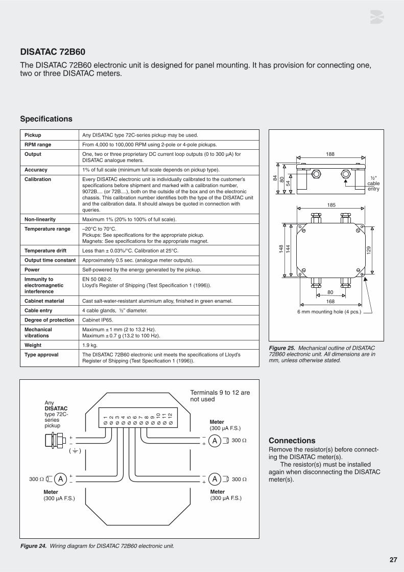
Figure 25. Mechanical outline of DISATAC72B60 electronic unit. All dimensions are inmm, unless otherwise stated.
Figure 24. Wiring diagram for DISATAC 72B60 electronic unit.
ConnectionsRemove the resistor(s) before connect-ing the DISATAC meter(s).
The resistor(s) must be installedagain when disconnecting the DISATACmeter(s).
Pickup Any DISATAC type 72C-series pickup may be used.
RPM range From 4,000 to 100,000 RPM using 2-pole or 4-pole pickups.
Output One, two or three proprietary DC current loop outputs (0 to 300 µA) for DISATAC analogue meters.
Accuracy 1% of full scale (minimum full scale depends on pickup type).
Calibration Every DISATAC electronic unit is individually calibrated to the customer’s specifications before shipment and marked with a calibration number, 9072B.... (or 72B....), both on the outside of the box and on the electronic chassis. This calibration number identifies both the type of the DISATAC unit and the calibration data. It should always be quoted in connection with queries.
Non-linearity Maximum 1% (20% to 100% of full scale).
Temperature range –20°C to 70°C.Pickups: See specifications for the appropriate pickup.Magnets: See specifications for the appropriate magnet.
Temperature drift Less than ± 0.03%/°C. Calibration at 25°C.
Output time constant Approximately 0.5 sec. (analogue meter outputs).
Power Self-powered by the energy generated by the pickup.
Immunity to EN 50 082-2.electromagnetic Lloyd’s Register of Shipping (Test Specification 1 (1996)). interference
Cabinet material Cast salt-water-resistant aluminium alloy, finished in green enamel.
Cable entry 4 cable glands, ½” diameter.
Degree of protection Cabinet IP65.
Mechanical Maximum ± 1 mm (2 to 13.2 Hz). vibrations Maximum ± 0.7 g (13.2 to 100 Hz).
Weight 1.9 kg.
Type approval The DISATAC 72B60 electronic unit meets the specifications of Lloyd’s Register of Shipping (Test Specification 1 (1996)).
Specifications
DISATAC 72B60The DISATAC 72B60 electronic unit is designed for panel mounting. It has provision for connecting one,two or three DISATAC meters.

28
Figure 27. Mechanical outline of DISATAC72B61 electronic unit. All dimensions are inmm, unless otherwise stated
Figure 26. Wiring diagram for DISATAC 72B61 electronic unit.
ConnectionsRemove the resistor(s) before connect-ing the DISATAC meter(s).
The resistor(s) must be installedagain when disconnecting the DISATACmeter(s).
Pickup Any DISATAC type 72C-series pickup may be used.
RPM range From 4,000 to 100,000 RPM using 2-pole or 4-pole pickups.
Meter output One or two proprietary DC current loop outputs (0 to 300 µA) for DISATAC analogue meters.
Recorder output One recorder output. Adjustable between 30 and 90 mV DC, corresponding to full-scale meter reading.
Output resistance 100 to 300 Ω.(recorder output)
Ripple(recorder output)
Output time constant Analogue meter outputs: Approximately 0.5 sec. Recorder output: 0.1 to 0.3sec.
Accuracy 1% of full scale (minimum full scale depends on pickup type).
Calibration Every DISATAC electronic unit is individually calibrated to the customer’s specifications before shipment and is marked with a calibration number, 9072B.... (or 72B....), both on the outside of the box and on the electronic chassis. This calibration number identifies both the type of the DISATAC unit and the calibration data. It should always be quoted in connection with queries.
Non-linearity Maximum 1% (20% to 100% of full scale).
Temperature range –20°C to 70°C. Pickups: See specifications for the appropriate pickup.Magnets: See specifications for the appropriate magnet.
Temperature drift Less than ± 0.03%/°C. Calibration at 25°C.
Power Self-powered by the energy generated by the pickup.
Immunity to electro- EN 50 082-2. magnetic interference Lloyd’s Register of Shipping (Test Specification 1 (1996)).
Cabinet material Cast salt-water-resistant aluminium alloy, finished in green enamel.
Cable entry 4 cable glands, ½” diameter.
Degree of protection Cabinet IP65.
Mech. vibrations Maximum ±1 mm (2 to 13.2 Hz). Maximum ± 0.7 g (13.2 to 100 Hz).
Weight 1.9 kg.
Type approval The DISATAC 72B61 electronic unit meets the specifications of Lloyd’s Register of Shipping (Test Specification 1 (1996)).
Specifications
DISATAC 72B61 The DISATAC 72B61 electronic unit is a recorder version for panel mounting, with provision for connectingone recorder and one or two meters.
120,000Number of poles * RPM % maximum.
29
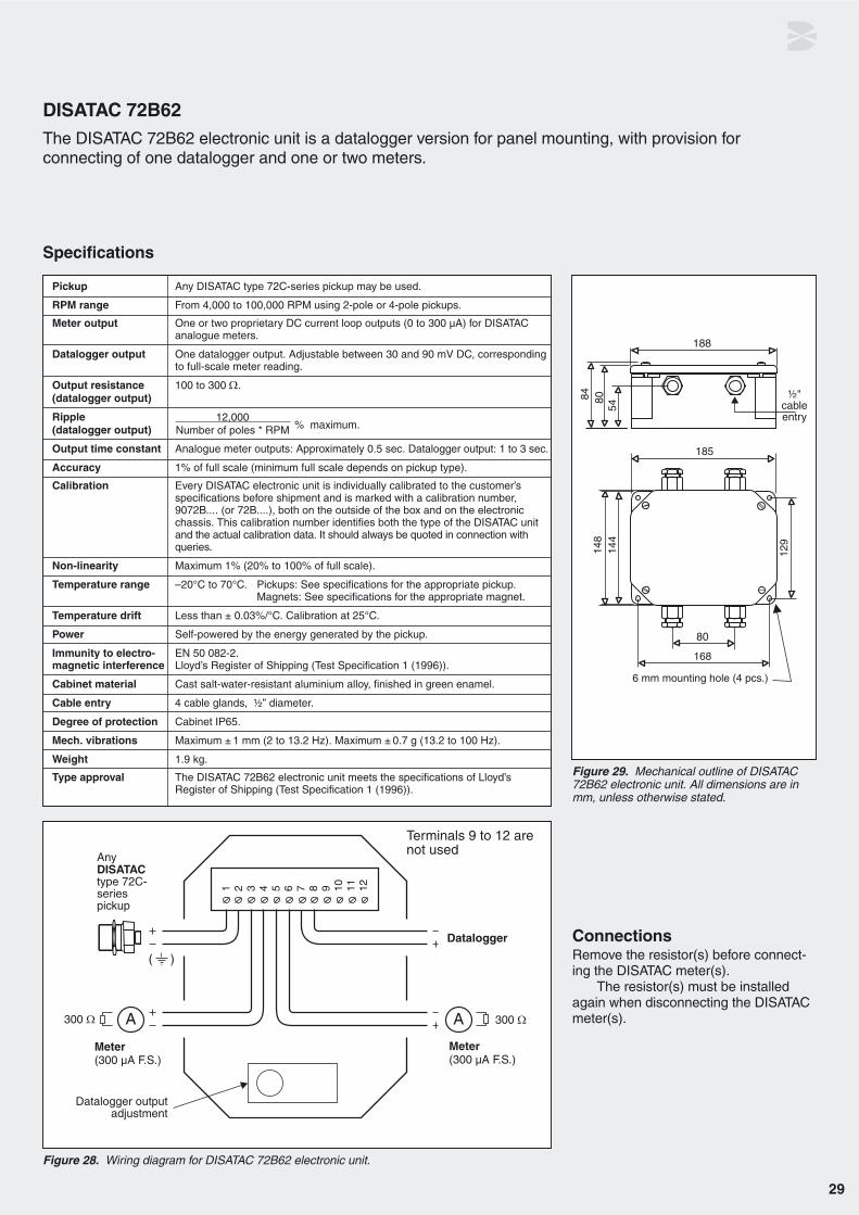
Figure 28. Wiring diagram for DISATAC 72B62 electronic unit.
Figure 29. Mechanical outline of DISATAC72B62 electronic unit. All dimensions are inmm, unless otherwise stated.
ConnectionsRemove the resistor(s) before connect-ing the DISATAC meter(s).
The resistor(s) must be installedagain when disconnecting the DISATACmeter(s).
Pickup Any DISATAC type 72C-series pickup may be used.
RPM range From 4,000 to 100,000 RPM using 2-pole or 4-pole pickups.
Meter output One or two proprietary DC current loop outputs (0 to 300 µA) for DISATAC analogue meters.
Datalogger output One datalogger output. Adjustable between 30 and 90 mV DC, corresponding to full-scale meter reading.
Output resistance 100 to 300 Ω.(datalogger output)
Ripple(datalogger output)
Output time constant Analogue meter outputs: Approximately 0.5 sec. Datalogger output: 1 to 3 sec.
Accuracy 1% of full scale (minimum full scale depends on pickup type).
Calibration Every DISATAC electronic unit is individually calibrated to the customer’s specifications before shipment and is marked with a calibration number, 9072B.... (or 72B....), both on the outside of the box and on the electronic chassis. This calibration number identifies both the type of the DISATAC unit and the actual calibration data. It should always be quoted in connection with queries.
Non-linearity Maximum 1% (20% to 100% of full scale).
Temperature range –20°C to 70°C. Pickups: See specifications for the appropriate pickup.Magnets: See specifications for the appropriate magnet.
Temperature drift Less than ± 0.03%/°C. Calibration at 25°C.
Power Self-powered by the energy generated by the pickup.
Immunity to electro- EN 50 082-2.magnetic interference Lloyd’s Register of Shipping (Test Specification 1 (1996)).
Cabinet material Cast salt-water-resistant aluminium alloy, finished in green enamel.
Cable entry 4 cable glands, ½” diameter.
Degree of protection Cabinet IP65.
Mech. vibrations Maximum ± 1 mm (2 to 13.2 Hz). Maximum ± 0.7 g (13.2 to 100 Hz).
Weight 1.9 kg.
Type approval The DISATAC 72B62 electronic unit meets the specifications of Lloyd’s Register of Shipping (Test Specification 1 (1996)).
Specifications
DISATAC 72B62 The DISATAC 72B62 electronic unit is a datalogger version for panel mounting, with provision for connecting of one datalogger and one or two meters.
12,000Number of poles * RPM % maximum.

30
Figure 31. Mechanical outline of DISATAC72B63 electronic unit. All dimensions are inmm, unless otherwise stated.
Figure 30. Wiring diagram for DISATAC 72B63 electronic unit.
ConnectionsRemove resistors between terminals 3and 4 and/or 5 and 6 before connectingmeters.
Install the resistor(s) again if themeter(s) are disconnected.
Pickup Any DISATAC type 72C-series pickup may be used.
RPM range From 4,000 to 100,000 RPM using 2-pole or 4-pole pickups.
Output One or two proprietary DC current loop outputs (0 to 300 µA) for DISATAC analogue meters. One isolated 4-20 mA DC recorder output (passive 2-wire transmitter).
Accuracy 1% of full scale (minimum full scale depends on pickup type).
Calibration Every DISATAC electronic unit is individually calibrated to the customer’s spe-cifications before shipment and is marked with a calibration number, 9072B....(or 72B....), both on the outside of the box and on the electronic chassis. This calibration number identifies both the type of the DISATAC unit and the actual calibration data. It should always be quoted in connection with queries.
Non-linearity Maximum 1% (20% to 100% of full scale).
Temperature range –20°C to 70°C. Pickups: See specifications for the appropriate pickup.Magnets: See specifications for the appropriate magnet.
Temperature drift Less than ± 0.03%/°C. Calibration at 25°C.
Output time constant Approximately 0.5 sec. (analogue meter outputs). Approximately 1.2 sec. (recorder output).
Power Self-powered by the energy generated by the pickup.
Ripple(recorder output)
Isolation Maximum 500 V AC (1 s), 50 V AC continuous.(recorder output)
Current loop supply 7.5 to 28 V DC. voltage (4 to 20 mA recorder output)
Immunity to electro- EN 50 082-2. magnetic interference Lloyd’s Register of Shipping (Test Specification 1 (1996)).
Cabinet material Cast salt-water-resistant aluminium alloy, finished in green enamel.
Cable entry 4 cable glands, ½” diameter.
Degree of protection Cabinet IP65.
Mech. vibrations Maximum ±1 mm (2 to 13.2 Hz). Maximum ± 0.7 g (13.2 to 100 Hz).
Weight 1.9 kg.
Type approval The DISATAC 72B63 electronic unit meets the specifications of Lloyd’s Register of Shipping (Test Specification 1 (1996)).
Specifications
DISATAC 72B63 The DISATAC 72B63 electronic unit is a meter version for panel mounting. It has provision for connectingone or two DISATAC meters and an additional recorder output with an isolated passive 2-wire transmitter(4-20 mA DC current loop).
12,000Number of poles * RPM % maximum.

31
Electronic units in the 72H-series

32
Figure 32. Mechanical outline of DISATAC 72H-series electronic units. All dimensions are inmm, unless otherwise stated.
Input Any 72K-series or 72C-series DISATAC pickup may be used.
Output The unit has a proprietary DISATAC DC current output (300 µA full scale). If more DISATAC meters are connected in series, the total impedance must not exceed 9 kΩ.
Ripple
Time constant 1.5 sec.
Recorder output 0 to 100 mV DC. (72H01) For recorders and dataloggers with a minimum internal impedance of 10 kΩ.
Recorder output Passive isolated 2-wire transmitter (4-20 mA DC). Isolation: max. 500 VAC (72H03) (1 sec.). 50 VAC cont. Current loop supply voltage:7.5 to 28 VDC.
Armature material Iron or iron alloy (72K.. pickups).
RPM range Rotational speeds corresponding to 3,600 - 600,000 pulses/min.
Accuracy ±1% of full scale when needle deflects.
Calibration Units are individually calibrated to customers’ specifications.
Temperature range Electronic unit: 0 to + 60°C.Pickups: See specifications for the appropriate pickup.
Temperature drift Less than ± 0.02%/°C (calibration at 25°C).
Immunity to EN 50 082-1.electromagneticinterference
Power supply Any voltage between 90 and 270 V AC - 50/60Hz.
Power consumption 1 VA (at 270 V AC).
Cabinet material Cast salt-water-resistant aluminium alloy, finished in green enamel.
Cable entry 5 cable glands, ½” diameter.
Degree of protection Cabinet IP65.
Mech. vibrations Maximum ± 0.7 g (13.2 to 100 Hz). Maximum ±1 mm (2 to 13.2 Hz).
Weight 2.25 kg.
Specifications
4,000Number of pulses/rev * RPM % maximum.
General descriptionThe DISATAC 72H-series electronictachometers are rugged and reliablesystems for contactless measurement ofthe rotational speed of almost any kindof rotating machinery. Since there is nomechanical connection to the rotatingmachine element, there is no mechani-cal wear.
The electronic units are designed tooperate with signals from a DISATAC72K-series pickup positioned next to anygear wheel, perforated disk, shaft withbosses or protrusions or equivalent,made from ferrous material. The rotatingpart of the machine acts as an armature.As the armature rotates, the changes inthe magnetic circuit induce electricalpulses in the pickup. The frequency ofthe pulses - e.g. produced by the teethon a gear wheel - is proportional to therotational speed. The induced pulsesare converted in the electronic units to acurrent proportional to the rotationalspeed (300 µA DC corresponds to full-scale deflection on an attached DISATAC meter).
The DISATAC 72H-series electronicunits are also compatible with DISATACtype 72C-series pickups with corre-sponding magnets attached to the rotat-ing parts.
The electronic units are calibrated inthe factory.
Calibration numberBefore shipment, every DISATAC 72H-series electronic unit is calibrated for theapplication concerned, to take accountof the number of pulses per revolutionand full-scale RPM. The unit is markedwith a calibration number, 9072H.... (or72H....), both on the outside of the boxand on the electronic chassis. This cali-bration number identifies both the typeof unit and the calibration data. It shouldalways be quoted in connection withqueries.
Minimum speed of rotationWhenever a reading of rotation speed isindicated by a DISATAC 72H-serieselectronic unit, it will be correct, withinthe specified limits of accuracy. Thus,there is no minimum-speed limitation.For values of lowest speeds indicatedrefer to the section on pickups.
NOTEAn error signal can be generated ifextraneous movement (e.g. vibration) ofthe armature tends to vary the gapbetween the pickup and the armature.The triggering level of the electronic unithas been selected so that, with pickupcable lengths of less than 25 metres, noadditional output error will be introducedunless the speed of any variation inarmature gap exceeds 200 mm/sec.
Electronic units in the 72H-series

33
Figure 33a. Wiring diagram for DISATAC 72H01 electronic unit.
Figure 33b. Wiring diagram for DISATAC 72H03 electronic unit.
ELECTRONIC UNITS - Specifications continued
Wiring diagram 72H01
Wiring diagram 72H03
InstallationMounting and connection of the 72H-series DISATAC Electronic Units mustcomply with local legislation for mountingand connection of electrical equipment -and the 72H-series DISATAC ElectronicUnit should only be installed by techni-cians familiar with installation of similarelectrical equipment. The 72H-series
DISATAC Electronic Unit must be con-nected to mains power through an exter-nal circuit breaker and a protective fuse(max. 10 A). The circuit breaker must beclearly marked with a label indicating thatit disconnects the mains power to the72H-series DISATAC Electronic Unit.The 72H-series Electronic Unit must beconnected to protective earth. Only the
earth screw on the chassis must be usedfor protective earth connection.
NOTETerminal 3 on the screw-terminal block isa functional earth connection and mustonly be used for connecting cable shieldsfrom e.g. 9072K150* DISATAC pickupcables.

34
The cable glands on the 72H-seriesElectronic Units allow for outer cable diameters of 7-13 mm.
The mains input cable must be mechanically secured close to the 72H-series Electronic Unit.
Disposal of electronic equipmentElectronic equipment should not be dis-posed of together with other waste. Theuser must dispose waste equipmentaccording to local rules and regulations.
DISATAC Electronic Tachometer Systems approvedby Lloyd’s Register of Shipping (IACS E10).

DISATAC meter

36
DescriptionMeters for the DISATAC electronictachometer must fulfil certain require-ments in order to operate properly withthe electronic circuit. The meter listed -the DQ 96 - is specially manufacturedfor use with the DISATAC system.
All DISATAC meters meet the speci-fications of Lloyd’s Register of Shipping(Test Specification no. 1 (1996)).
DISATAC meters must be ordered separately. When ordering, please specify:
• Type number of the meter
• Full-scale RPM
• Special requests (if any) for meter markings - e.g. a red-coloured sec-tion.
MountingThe dimensions on the panel cut-out for correct mounting are specified for eachmeter in the following sections. Somepanel-mounting meters are supplied withspecial shunts to compensate for sensi-tivity differences caused by mountingeither in magnetic or in non-magneticmaterial. The shunts should be removedwhen meters are mounted in panels ofmagnetic material. Instructions for doingthis are printed on the shunts.
DISATAC meter - DQ 96
Full scale deflection 300 µA ± 1%.
Internal resistance 300 Ω ± 10%.
Time constant 0.4-0.5 sec. to 63% of current applied.
General specifications
Mounting specifications
The housing for DQ 96 may be of eithermetal with bakelite front frame or blackglass-filled makrolon.
Figure 34. Mounting specifications of DISATAC meter DQ 96. All dimensions are in mm, unlessotherwise stated.
Mechanical dimensions and panel cut-out DQ 96
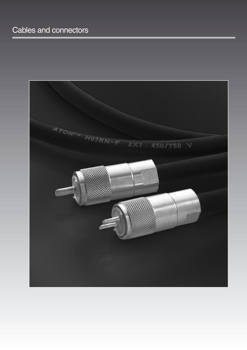
Cables and connectors

DescriptionCables and connectors for installing andconnecting the DISATAC system’s com-ponents must be ordered separately.
Cable typesThe cable required depends on the elec-tronic unit and the type of pickup in your application. Figure 39 shows the correctcables for the various applications.
The technical specifications for the indi-vidual cables and connectors are given at the end of this chapter.
Cable connectionsThe blue conductor in standard DISATACneoprene cables for 72C-series pickupsis connected to ground (earth).
Cable length limitationsFor 72K-series pickups, the length of thecable between pickup and the 72Hseries electronic unit should not exceed25 m.
For 72B-series of electronics units please refer to figure 40 on page 43.
Cables and connectors
Figures 39. DISATAC cable types.
DISATAC 72B50
DISATAC 72B30 & 72B60 - 63
DISATAC 72H01 & 72H03
38

Figure 40. Nomogram for calculating maximum length of cable.
Long pickup cables
When a long cable is used between the DISATAC pick-up and a 72B-series DISATAC electronic unit, it is necessary to take into consideration the limitation ofmax. speed of rotation imposed by the dielectric capaci-tance of the cable.
This chart shows the max. cable length betweenpickup and DISATAC electronic unit as a function ofmax. speed of rotation for 2-pole and 4-pole DISATACpickups.
Example:
For a 4-pole DISATAC pickup and a maximum of 25,000RPM, the maximum pickup cable length is 50 metres forstandard DISATAC neoprene cable and 125 metres forlow-capacitance RG11 A/U coaxial cable.
39

40
9140K0012 (standard cable, no connectors)
Cable length Specified by customer
Material Neoprene
Maximum ambient temperature +120°C
Outer diameter 9 mm
Colour Black
Conductors 2 (black and blue); 1 mm2 wire
SPECIFICATIONS
9006A1661 9006A1660 9072K1431 9072K1430 (for 72K-series (for 72K-seriespickups only) pickups only)
Cable length 2 m Specified by customer 2 m Specified by customer
Number of connectors 1 1 1 1
Connector type Coaxial type SO-239 Coaxial type SO-239 UHF twin type SO-264 UHF twin type SO-264
Cables between electronic units and meters
Cable connections between pickups and electronic units
9072K2211 9072K2221(for 72C-series pickups only) (for 72K-series pickups only)
Type SO-239 (coaxial type) SO-264 (UHF twin type)
Material Brass (silver-plated)/PTFE Brass (silver-plated)/PTFE
Connectors
NoteThe blue conductor in standard DISATACneoprene cables for 72C-series pickups isconnected to ground (earth).
Junction box 9072K2451 Mechanical outline
This junction box is specially intended for joining the special DISATAC neoprene pickup cable with other types of cable if theDISATAC electronic unit is mounted away from the pickup.
Note:For maximum lengths of pickup cables in DISATAC systemsplease refer to Figure 40 on page 43.
Terminals Max. 2.5 mm2 conductor
Cabinet material Aluminium alloy, finished in grey enamel
Protection IP 65
Weight 0.42 kg
Cable glands PG 13.5
Figure 41. All dimensions are in mm.

41
This electronic limit switch is intendedfor use in warning and alarm circuitsmonitoring the output from DISATACelectronic tachometer systems.
This electronic limit switch is a par-tial replacement for the 72D01, 72D02,72D03 and 72D04 DISATAC Relays(only DISATAC Relay ’MODE 1’ and’MODE 2’ operations are supported/emulated).
The input of the electronic limitswitch is connected directly to the cur-
rent output of the DISATAC electronicunit (300 µA full scale).
The electronic limit switch consistsof two electro-mechanical relays con-trolled by an electronic circuit causingthe relay contacts to open or close atpreset SETPOINT values. ’normallyopen’ or ’normally closed’ operation ofthe two relays can be selected using ajumper contact located inside the elec-tronic unit.
Note:The two circuits are configured for ’normally open’ operation if not other-wise specified with the order.
The two SETPOINTS are program-med (0 to 99.9%) using 3 push buttonson the electronic module.
Electronic Limit Switch 9072D4701
Wiring diagram
Figure 42.

42
Figure 43. All dimensions are in mm.
ELECTRONIC LIMIT SWITCH - Specifications continued
Mechanical dimensions
Power supply A) 24 VDC +/-20% 1.5 W (specify with order) B) 115 VAC +/-10% 4 W
C) 230 VAC +/-10% 4 W
Temperature range -20 to +60°C
Input sensivity 100% equal to 300 µA DC
Setpoint accuracy Error less than 1% of full scale (100%) within full temperature range
Time Constant 1 sec.
Relay contacts Max. voltage 250 VAC RMS(’normally open’ operation if not Max. current 2A AC 50/60 Hz otherwise specified) Max. AC power 500 VA / 100 W
Max. load at 24 VDC 1 A
Insulation 3.75 kV AC
Cabinet material Aluminium alloy, finished in grey enamel
Weight 1.7 kg
Cable glands PG 13.5
Protection IP 65
Specifications

43
Figure 44. All dimensions are in mm.
DISATAC SELECTOR SWITCH - 2, 4 or 8 input channels
Mechanical dimensions(2 input channel version as example below)
A mechanically operated selector switch tobe used between a number of DISATACpickups (same type) and one DISATACelectronic unit if continuous monitoring ofeach pickup is not required.
The selector switch is manufacturedon special request in 2, 4 or 8 input chan-nel versions.
2 input channel versionPartnumber 9072K2461
4 input channel versionPartnumber 9072K2471
8 input channel versionPartnumber 9072K2481
Cabinet material Cast aluminium alloy with grey enamel finishing.
Protection IP 54
Cable entries PG 13.5 cable glands
Mechanical dimensions Depends on number of input channels Example: 2 input channel switch: 100 x 100 x 80 mm (See mechanical outline above).

44
Meter reading
No meter reading
Half the correctmeter reading
Twice the correctmeter reading
Product
All types ofpickups
72C-series2-pole
pickups
72C-series4-pole
pickups
72K-series pickups
All types of pickups
72C-series2-pole
pickups
2 or more meters
All 72B-seriesDISATACsystems
72C- series4-pole
pickups
Possible cause of fault
The pickup and/or magnet may bedamaged or misaligned.
Open- or short-circuit fault in pickup cable.
Open-circuit fault in the pickup coil.
Open-circuit fault in the pickup coil.
Open-circuit fault in the pickup coil.
The meter cable is short-circuited or not connected correctly or there is an internal open-circuitfault in the meter
There is a fault in the DISATACelectronic unit.
The electronic unit may havebeen calibrated for a 4-pole pick-up.
2 DISATAC meters may by mistakehave been connected in parallel.
The corresponding 300 Ωresistor on the terminal block wasnot removed when the meter cable was connected.
The DISATAC electronic unit mayhave been calibrated for a 2-pole pickup.
How to check/repair
Check by visual inspection that the pickup and magnet are mounted correctlyas specified in this catalogue and check that neither pickup nor magnet hasbeen mechanically damaged.
If there is damage, the affected parts must be replaced with exactly the sametypes.
Check cable, connections and isolation to ground.
72C.. pickups have the outer conductor connected to ground.
In 72K.. pickups, the pickup coil is not connected to ground.
Repair or replace cable if necessary.
Check that the internal resistance in cable and pickup is approx. 2600-3000 Ω(at room temperature).
If the resistance deviates, replace the pickup with a new one of the same type.
Check that the internal resistance in cable and pickup is approx. 800-1000 Ω(at room temperature).
If the resistance deviates, replace the pickup with a new one of the same type.
Check that the internal resistance in cable and pickup is approx. 1100-1300 Ωat room temperature).
If the resistance deviates, replace the pickup with a new one of the same type.
Check the meter circuit. A 4.5V battery connected to the meter cable in serieswith a 15 kΩ resistor should give approx. full scale deflection on the meter.
If not, check the cable or replace the meter if necessary. When ordering a newmeter from your DISATAC dealer, specify meter type and full-scale reading(max. RPM.). Remember to specify any special markings needed on the scale.
Check cable connections against the wiring diagram in the cabinet and correctwiring if necessary.
Check that all screws in the terminal block are fastened securely.
As each DISATAC electronic unit is individually calibrated and checked, a defective electronic unit should always be returned to Dantec Dynamics forrepair/recalibration or replaced by a new unit with the same calibration specification. When ordering a replacement unit, remember to give the DISATAC calibration number on the calibration label.
Check with the calibration label on the DISATAC electronic unit that it is actually calibrated for a 2-pole pickup.
Check that pickup and magnet are 2-pole types.
If necessary, replace the DISATAC electronic unit with a unit that has beencalibrated for a 2-pole pickup. Alternatively, replace pickup and magnet with 4-pole types (if possible).
Check the meter connections against the wiring diagram in the cabinet andcorrect if necessary.
Check terminal block connections.
Check with the calibration label on the DISATAC electronic unit that it is actually calibrated for a 4-pole pickup.
Check that pickup and magnet are 4-pole types.
If necessary, replace the DISATAC electronic unit with a unit that has beencalibrated for a 4-pole pickup. Alternatively, replace pickup and magnet with 2-pole types (if possible).
DISATAC systems will normally operate for years without requiring maintenance. However, if a fault doesoccur, this chart will help to locate the cause. Most faults are due to installation errors or the use of wrongcombinations of DISATAC electronic units and pickups/magnets.
Service and Troubleshooting

Meter reading
Meter reading 5 - 10% too low
Meter reading 5 - 10% too high
Low meterreading
Low rotational speeds notindicated
Unstable reading at low rotational
speeds
Erratic and un-stable reading
Meter reading iscorrect butrecorder/
datalogger output is too low
Meter reading iscorrect but
recorder output istoo low
Product
DISATAC meters,type
DQ 96R, DQ 144R DS 95A/K, DS 120A or
DS 185 mounted in a steel panel
DISATAC meters,type DQ 96R,
DQ 144R, DS 95A/K, DS 120A or
DS 185 mounted ina non-ferrous panel.
72C-series2-pole
pickups
72C-series4-pole
pickups
All types of pickups
72K-seriespickups
72C-series4-pole pickups
All types of pickups
72B61, 72B62 and72H01
72B63
Possible cause of fault
The meter is placed in a ferrouspanel with the special compen-sation shunt installed on meterterminals.
The meter is placed in a non-ferrous panel without the specialcompensation shunt installed onmeter terminals.
Pickup and magnet are not positioned correctly in relation toeach other.
Pickup and magnet are not positioned correctly in relation toeach other.
There is a fault in the meter circuit.
There is a fault in the DISATACelectronic unit.
The spacing between pickupand armature is incorrect.
Too large a spacing betweenpickup and magnet.
May be caused by unstable connections.
External recorder/dataloggerhas too low an input impedance- or setting of ’Adjustment’potentiometer in DISATAC electronic unit is not correct
Problem with 4-20 mA currentloop supply voltage - or too highimpedance in current loop.
How to check/repair
If installed, the compensation shunt must be removed.
Check that the panel thickness is between 0.5 and 3 mm. If the panel is thick-er than 3 mm, the cut-out in the panel must be bigger (see specifications inthe meter section of this catalogue).If the size of the cut-out is incorrect, remove the meter and correct the cut-outin accordance with meter specifications.
NB: DISATAC meters DQ 96, DQ 96S, DQ144 and DQ 144S do not requirethe special compensation shunt when mounted in a non-ferrous panel.
If the compensation shunt is not installed, the correct type must be installedon meter terminals. A spare shunt can be ordered from your DISATAC dealer.Remember to specify meter type.
NB: DISATAC meters DQ 96, DQ 96S, DQ144 and DQ 144S do not requirethe special compensation shunt when mounted in a non-ferrous panel.
Check that pickup and magnet are positioned in accordance with the specifications in the pickup section of this catalogue.
Check that pickup and magnet are positioned in accordance with the speci-fications in the pickup section of this catalogue. In particular, check that the spacing between pickup and magnet is 1.4 ±0.6 mm.
Check the meter circuit. A 4.5V battery connected to the meter cable in serieswith a 15 kΩ resistor should give approx. full-scale deflection on the meter.
If not, check the cable or replace the meter if necessary. When ordering a newmeter from your DISATAC dealer remember to specify meter type and full-scale reading (max. RPM). Remember to specify any special markings on the scale.
Check cable connections against the wiring diagram in the cabinet and correctwiring if necessary.
Check that all screws in the terminal block are fastened securely.
As each DISATAC electronic unit is individually calibrated and checked, a defective electronic unit should always be returned to Dantec Dynamics forrepair/recalibration or replaced by a new unit with the same calibration specifications. When ordering a replacement unit, remember to give the DISATAC calibration number on the calibration label.
Check that the spacing is 1 mm.
Adjust to correct distance if necessary.
Check that the spacing between pickup and magnet is 1.4 ±0.6 mm. Adjust the distance if necessary.
Check for unstable connections in DISATAC electronic unit, pickup connector,junction boxes and meter terminals.
Check technical specifications for recorder/ datalogger. Input impedanceshould be 10 kΩ or higher.
Adjust potentiometer in DISATAC electronic unit if necessary (72B6. only).
NB: In 72H01, the ’adjustment’ potentiometer is preset at the factory andmust not be re-adjusted.
Check voltage and polarity between terminals 7-8 in the DISATAC electronicunit with a high impedance voltmeter. The measured voltage should bebetween 7.5 and 28V DC.
Disconnect the cable from terminals 7-8 in the DISATAC electronic unit and connect a 330 Ω resistor between the 2 wires of the cable. The measuredvoltage across this resistor must be 7.0V DC as a minimum.
SERVICE AND TROUBLESHOUTING CONTINUED
45

46
Certificate

47
Certificate

Certificate
48

49
Certificate

Certificate
50
51
Certificate

52

53
Ordering procedure and list of current DISATAC representatives
Ordering procedure:When ordering a new DISATAC installa-tion or DISATAC spare parts, pleasealways provide the representative with thedetails stated in the order form. (Pleasecopy the order form provided on page 54).
This will ensure rapid and correct handlingof the order. If there is no representative in your country, please e-mail the order to DantecDynamics A/S, Denmark.
CHINA (mainland - excl. Hong Kong) (for Hong Kong, please contact Dantec Dynamics A/S, Denmark) Bond InstrumentationShanghai Representative office Tel: + 86 21 5888 6398 Fax: + 86 21 5888 6025E-mail: [email protected](Mr. Wu Qi)
DENMARK Dantec Dynamics A/S Tel: + 45 44 57 81 95Fax: + 45 44 57 80 01 E-mail:[email protected]
FRANCE, NOZAY Dantec Dynamics S.A.S., Nozay Tel: + 33 1 64 49 6830 Fax: + 33 1 64 49 6839E-mail: [email protected]
GERMANY Karl-Wilhelm Henn KGMeß- und Regeltechnik Tel: + 49 40 254 056-11 Fax: + 49 40 254 056-55 E-mail: [email protected]: www.kw-henn.de
GREECEMantanovitch-Katsaros S.A.Tel: + 30 210 461 1010 Fax: + 30 210 461 7519E-mail: [email protected]
HOLLAND Peekel Instruments B.V. Tel: + 31 104 152 722 Fax: + 31 104 376 826E-mail: [email protected]: www.peekel.nl
ITALY La Meccanica Turbo Diesel S.r.l. Tel: + 39 10 246 1111 Fax: + 39 10 246 1144E-mail: [email protected]
SWEDEN VIDIX Visible Dynamics ABTel: +46 (0) 733 50 33 66Fax: +46 (0) 8 510 508 10 E-mail (Sales): [email protected]: www.vidix.se
UNITED KINGDOMDantec Dynamics LtdTel: + 44 1 275 375 333 Fax: + 44 1 275 375 336E-mail: [email protected]
UNITED STATES OF AMERICA Dantec Dynamics, Inc.Tel: + 1 631 654 1290Fax: + 1 631 654 1293 E-mail: [email protected]
FOR ALL OTHER COUNTRIES:Dantec Dynamics A/STonsbakken 16 - 18 DK-2740 Skovlunde DenmarkTel: + 45 44 57 81 95 Fax: + 45 44 57 80 01 E-mail:[email protected]
DISATAC representatives:

54
DISATAC order form (Please photocopy this form)
To (DISATAC representative): Fax number:
(A) Details about the turbocharger:
Manufacture: Type: Year of manufacture: Maximum RPM: Pulses per revolution:(72H/72K-systems only)
(B) Ordering information: New installation Spare parts
Configuration of the DISATAC equipment depends on the make of the turbocharger specified in box A. For correct specification of system components, please refer to the DISATAC product selection guide (page 7). (Please complete all ordering details).
Item: Quantity Type number and other specifications:
(1) Pickup Type: __________________________________
(2) Magnet Type: __________________________________
NB: Magnet only needed with 72C-series pickups
(3) Pickup cable Standard length (2 m) or ____________ m of cable
(4) Electronic unit Type: __________________________________
IMPORTANT: When ordering a replacement unit, please indicate the calibration code number affixed to the present electronic unit.
Calibration code number: ___________________
(5) Meter cable Standard length (10 m) or ____________ m of cable
Code number: ___________________________
(for the correct code number, please refer to the configuration guide on page 6)NB: Cables are made of neoprene
(6) Meter for DISATAC: Type: __________________________________
Full-scale RPM reading: ___________________
Special marking on the meter: ________________________________________________________
For PR 5515 Digital meter please specify supply voltage: ___________________________________
Special accessories:
(C) Company details
Invoice address Delivery address (same as invoice address)
Company: Company:
Attn.: Attn.:
Street & No.: Street & No.:
City/state: City/state:
Post/ZIP code: Post/ZIP code:
Country: Country:
Order number: Ref:
Phone number:
E-mail:
Signature: Date:
Example:
Calibrationcodenumber

About Dantec Dynamics
Worldwide representation
Dantec Dynamics is the leading provider of systems for measurements of rotation, flow, velocity and particlesize. Since 1947 we have provided solutions for customers to optimize their component testing and products.Our large number of customers benefit from our quality solutions within:
From our six offices and more than 30 representatives worldwide weapproach our customers individually. We examine the specific needsand find the best solution for you. For us you are a long-term partnerin improving efficiency, safety and quality of life.A list of representatives is available at our website.
DENMARK (headquarters)Dantec Dynamics A/[email protected]
www.disatac.com
Publication No.: 237_v4 - 9040U1013
Fluid Mechanics
Particle Characterization
Combustion Diagnostics
Thermal Comfort
Microfluidics
Process Control
Strain, Stress & Vibration
Non-destructive Testing
Disatac Tachometers
The specifications in this document are subject tochange without notice. Dantec Dynamics is trademark of Dantec Dynamics A/S.
Dantec Dynamics, a Nova Instruments company