direction-finding sonar system for autonomous submarine nicole rennalls, estee amana, frederick...
TRANSCRIPT

Direction-Finding Sonar System for Autonomous Submarine
Nicole Rennalls, Estee Amana, Frederick Ealick, Mitcham Costley
ECE Department
Georgia Institute of Technology
ECE4007 L01
December 1, 2008
Project Overview
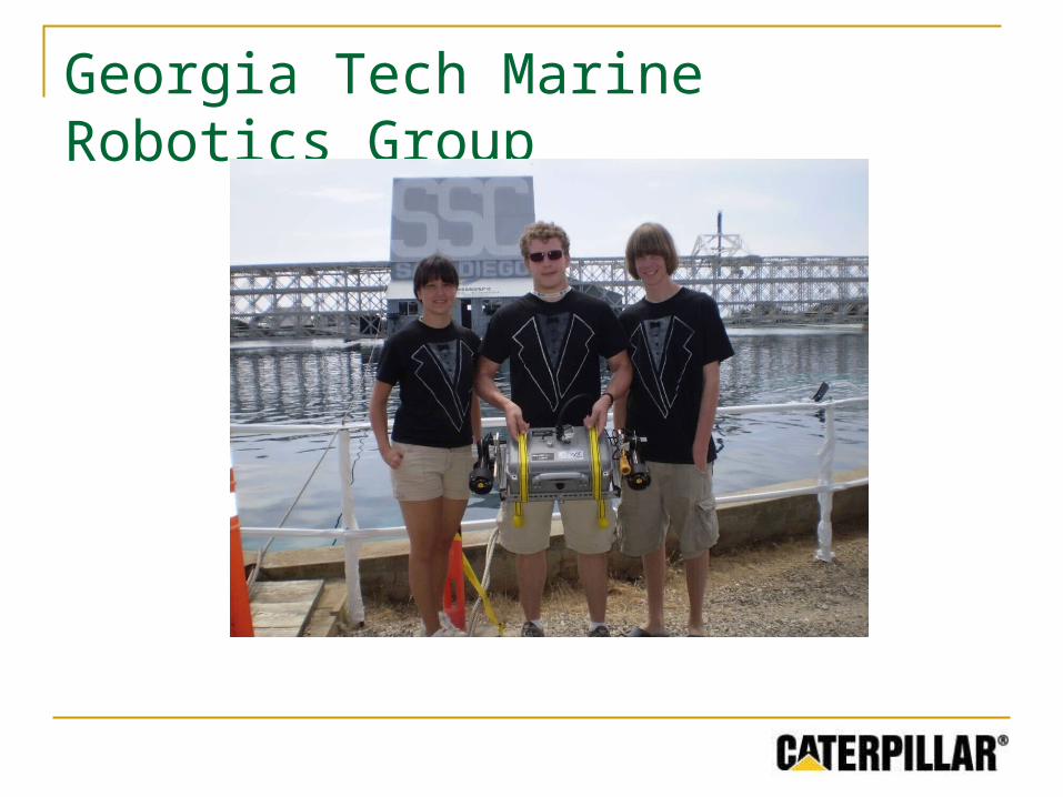
Georgia Tech Marine Robotics Group
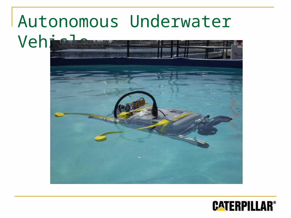
Autonomous Underwater Vehicle
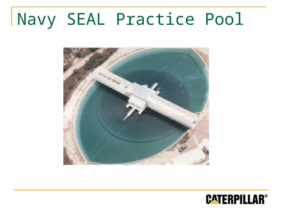
Navy SEAL Practice Pool
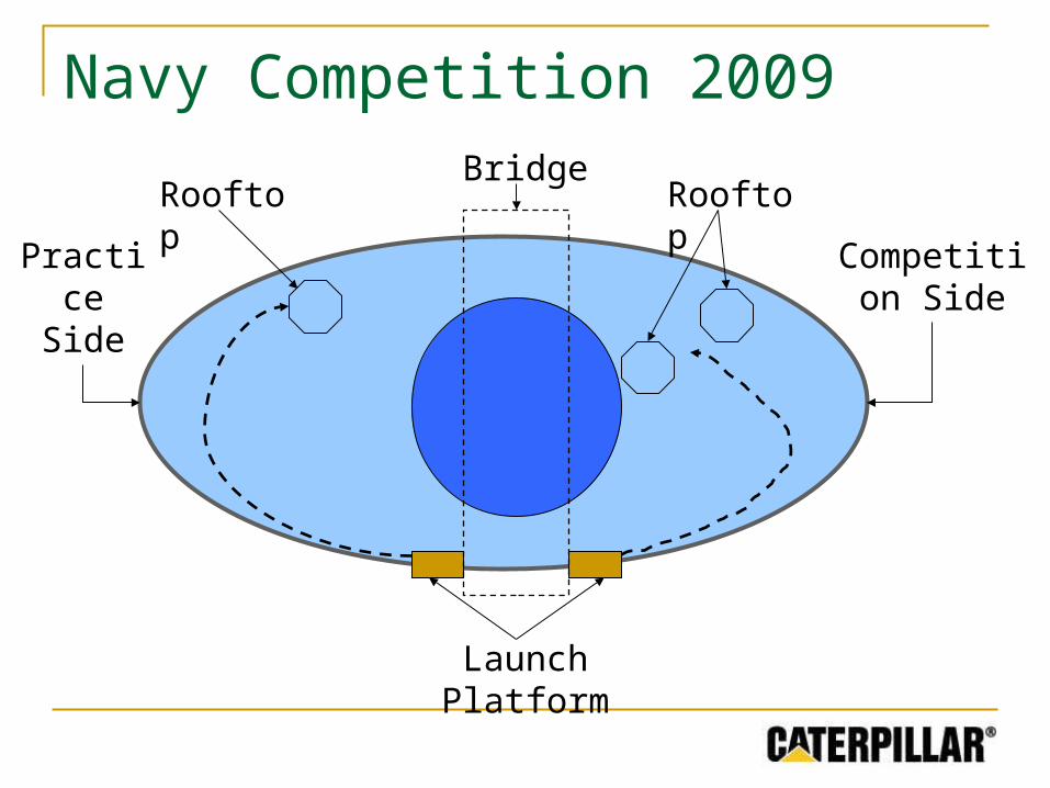
Navy Competition 2009
Launch Platform
Practice Side
Competition Side
BridgeRooftopRooftop
Mission
To build a sonar system under $400 to complete the “Rooftop” task, which improves upon previous design group efforts

Design Objectives
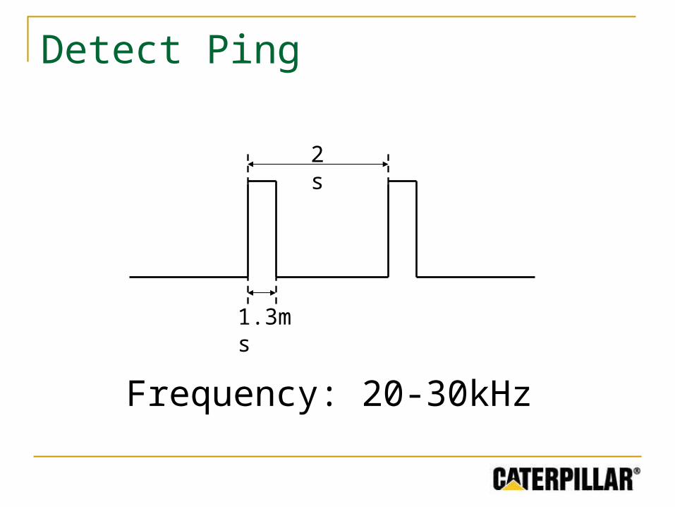
Detect Ping
Frequency: 20-30kHz
2s
1.3ms
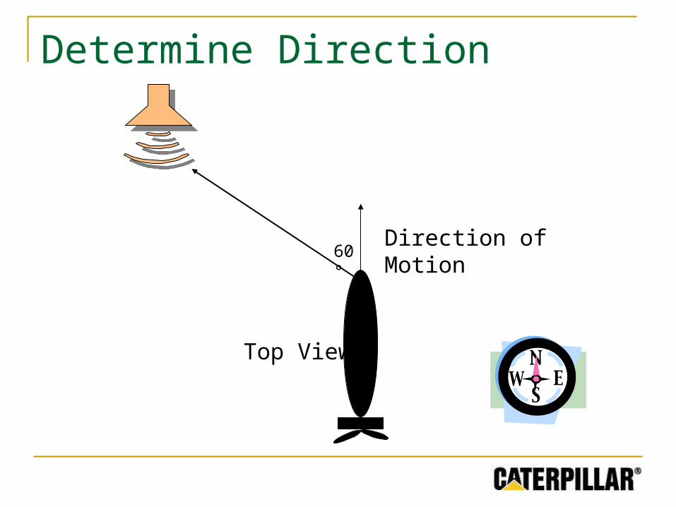
60°
Determine Direction
Top View
Direction of Motion
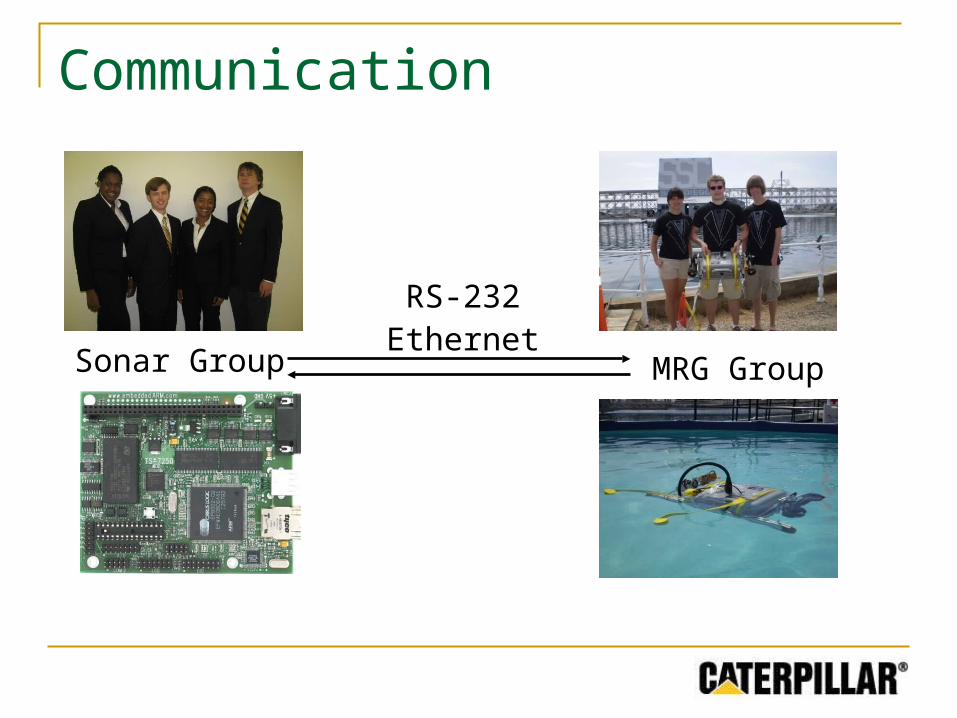
MRG GroupSonar Group
RS-232Ethernet
Communication
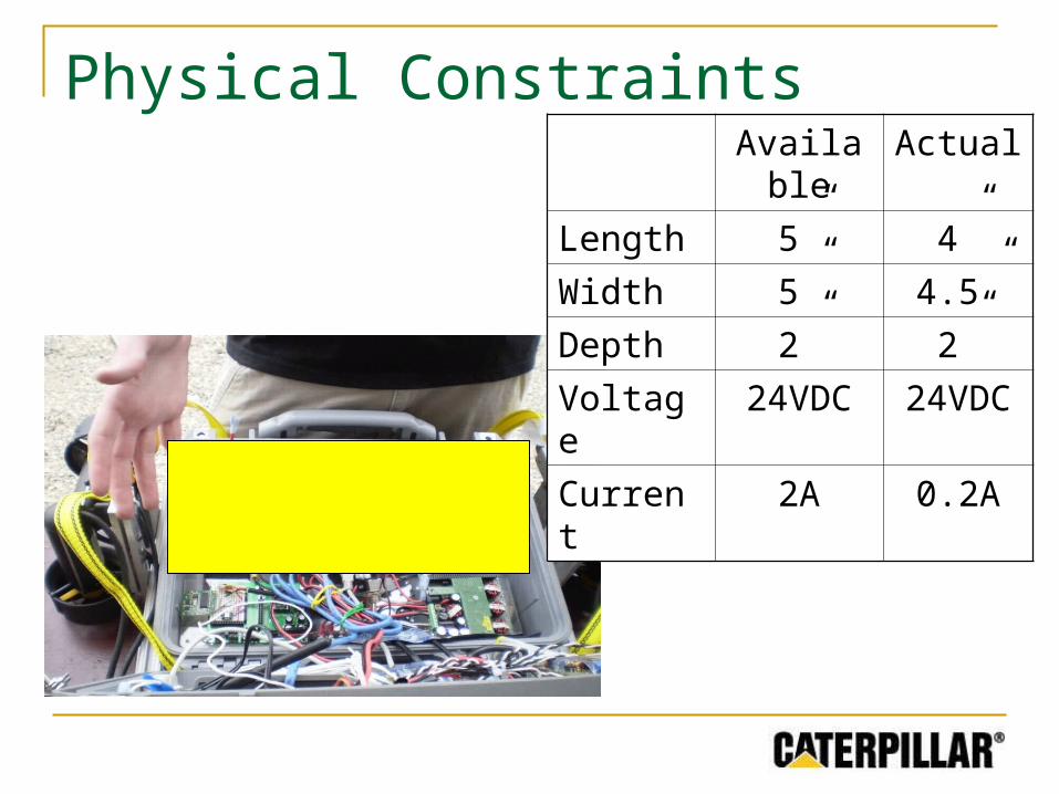
Physical ConstraintsAvailable Actual
Length 5” 4”
Width 5” 4.5”
Depth 2” 2”
Voltage 24VDC 24VDC
Current 2A 0.2A
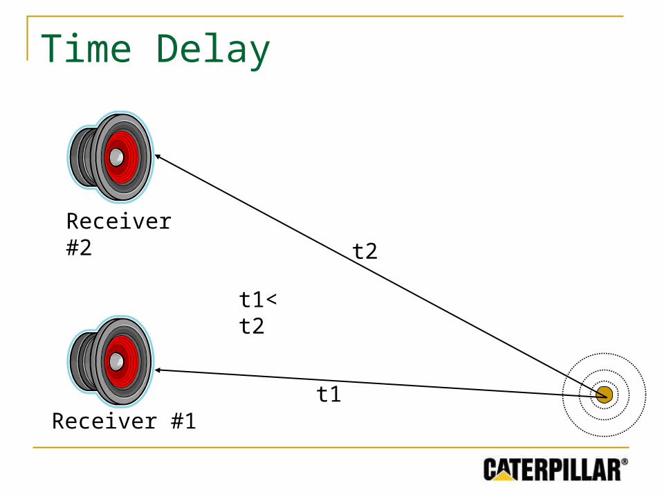
t1
t2
t1< t2
Time Delay
Receiver #1
Receiver #2
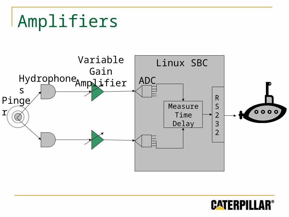
Technical Approach
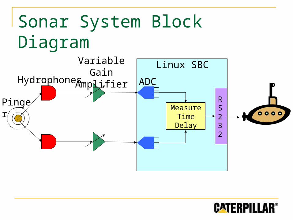
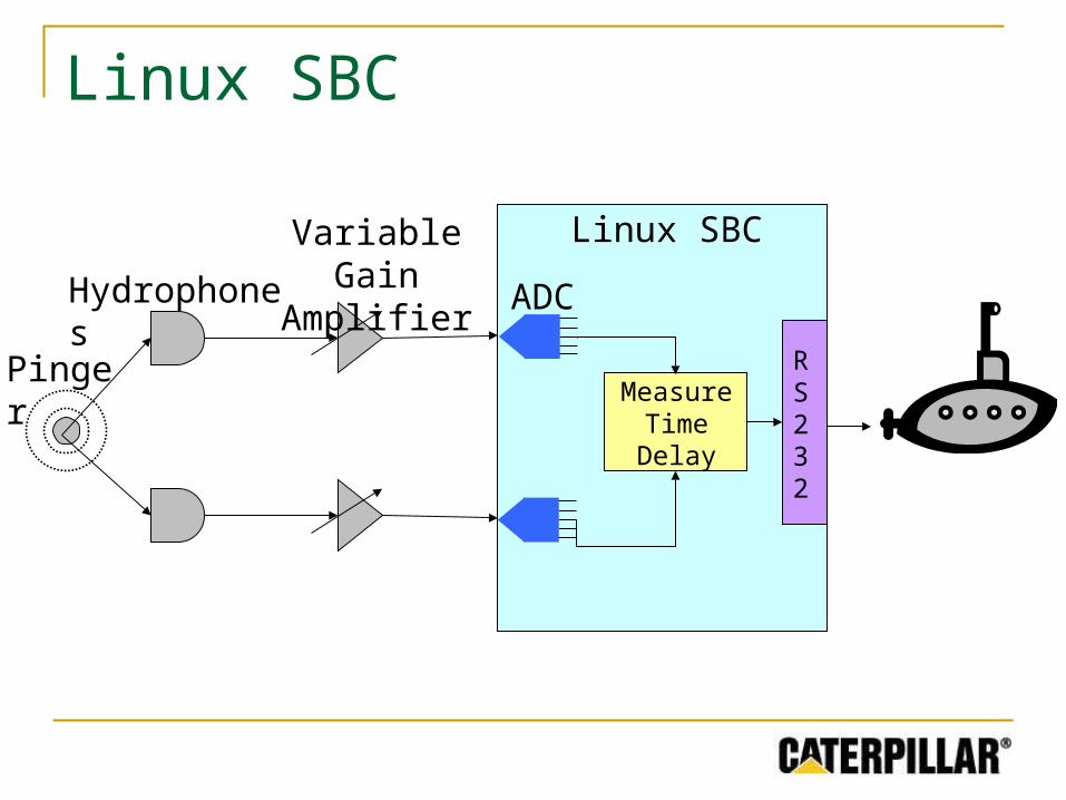
Sonar System Block Diagram
Hydrophones
Pinger
Variable Gain Amplifier
ADC
Measure Time Delay
RS232
Linux SBC
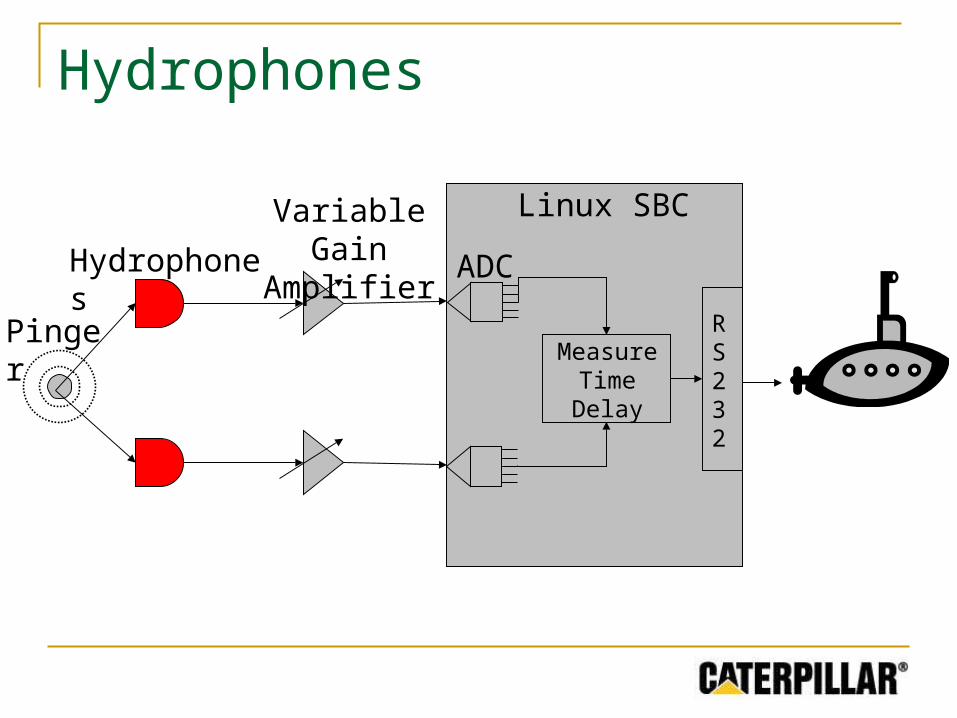
Hydrophones
Hydrophones
Pinger
Variable Gain Amplifier ADC
RS232
Linux SBC
Measure Time Delay
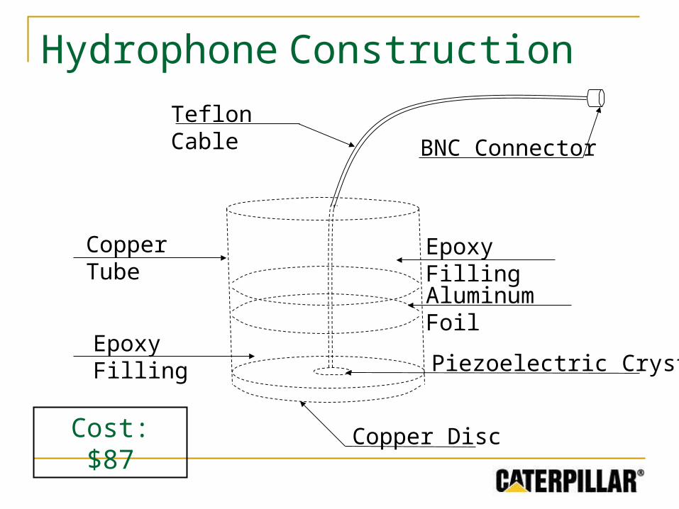
Copper Disc
Copper Tube
Teflon Cable
BNC Connector
Epoxy Filling
Hydrophone Construction
Cost: $87
Piezoelectric Crystal
Epoxy Filling
Aluminum Foil

Hydrophone Testing
PVC Pipe
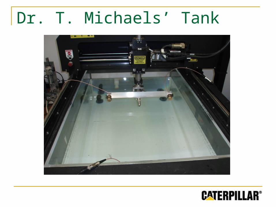
Dr. T. Michaels’ Tank
Amplifiers
Hydrophones
Pinger
Variable Gain Amplifier
ADC
RS232
Linux SBC
Measure Time Delay
MAX4196
Single-supply Rail-to-rail output (within 200 mV) Drawbacks:
Inconsistent gain across frequency band Complexity associated with four stages Gain adjustment difficult
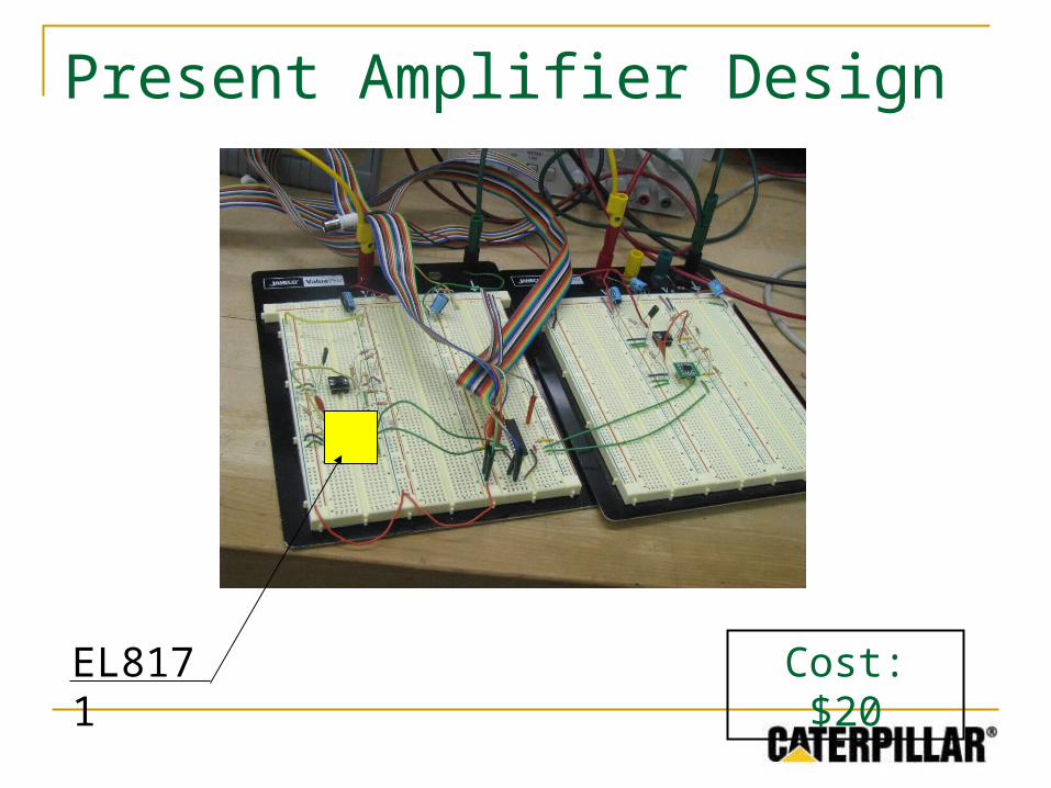
Present Amplifier Design
Cost: $20EL8171
Intersil EL8171
Single-supply Rail-to-rail output (within 0 mV) Advantages:
PMOS input Stable gain across frequency band Fewer stages
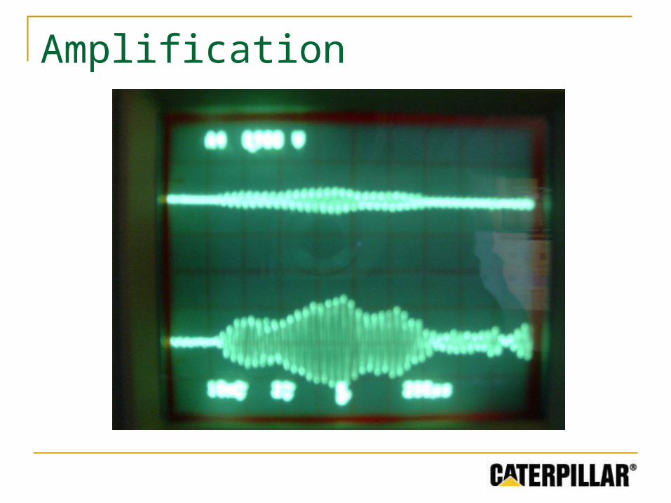
Amplification
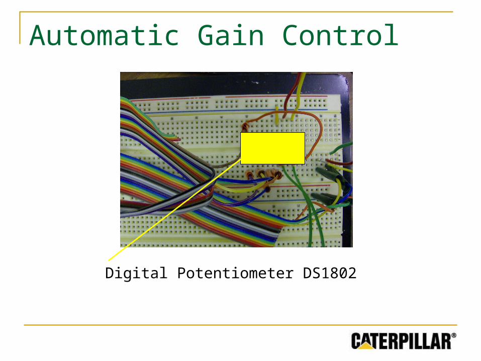
Automatic Gain Control
Digital Potentiometer DS1802
Linux SBC
Hydrophones
Pinger
Variable Gain Amplifier
ADC
RS232
Linux SBC
Measure Time Delay
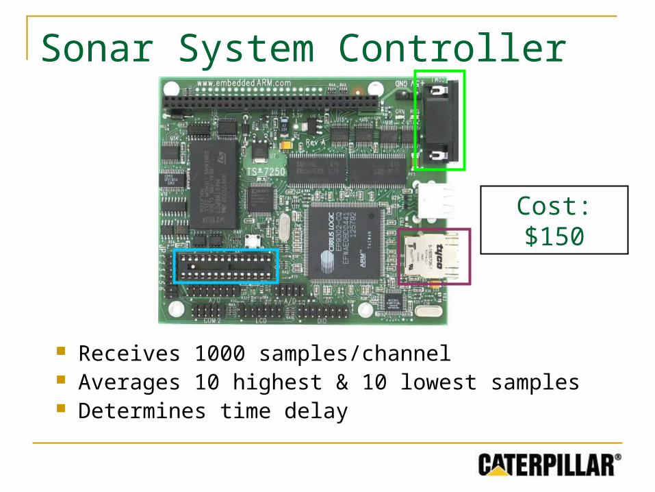
Sonar System Controller
Receives 1000 samples/channel Averages 10 highest & 10 lowest samples Determines time delay
Cost: $150
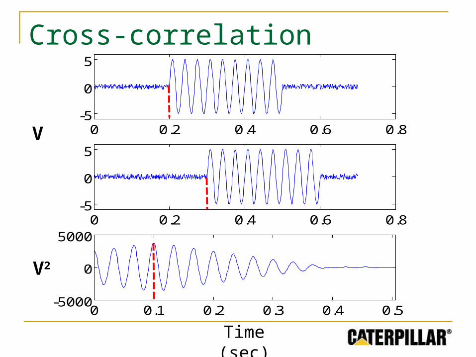
Cross-correlation
0 0.2 0.4 0.6 0.8-5
0
5
0 0.2 0.4 0.6 0.8-5
0
5
0 0.1 0.2 0.3 0.4 0.5-5000
0
5000
V
Time (sec)
V2
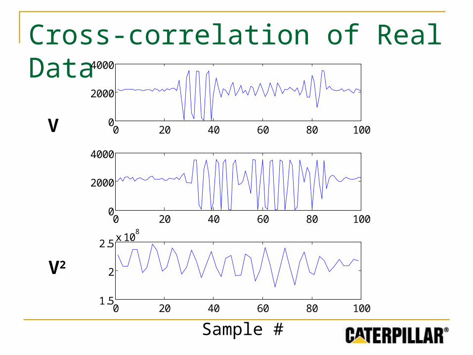
Cross-correlation of Real Data
0 20 40 60 80 1000
2000
4000
0 20 40 60 80 1000
2000
4000
0 20 40 60 80 1001.5
2
2.5x 10
8
V
V2
Sample #
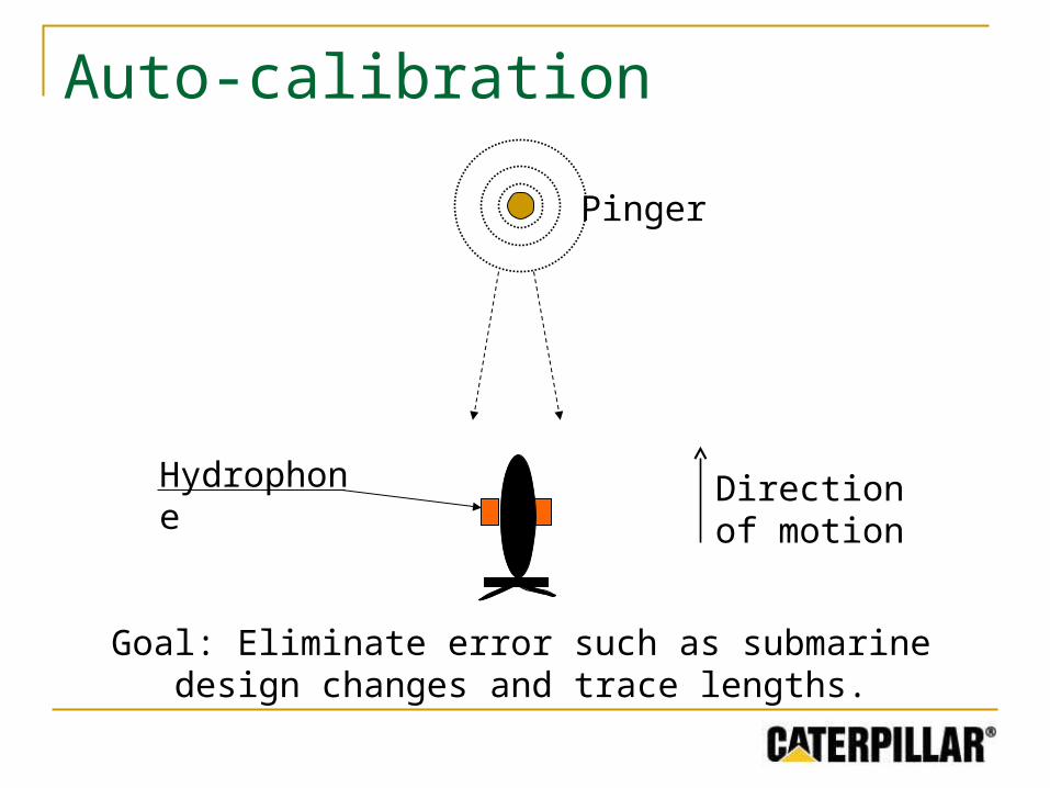
Auto-calibration
Goal: Eliminate error such as submarine design changes and trace lengths.
Hydrophone
Pinger
Direction of motion
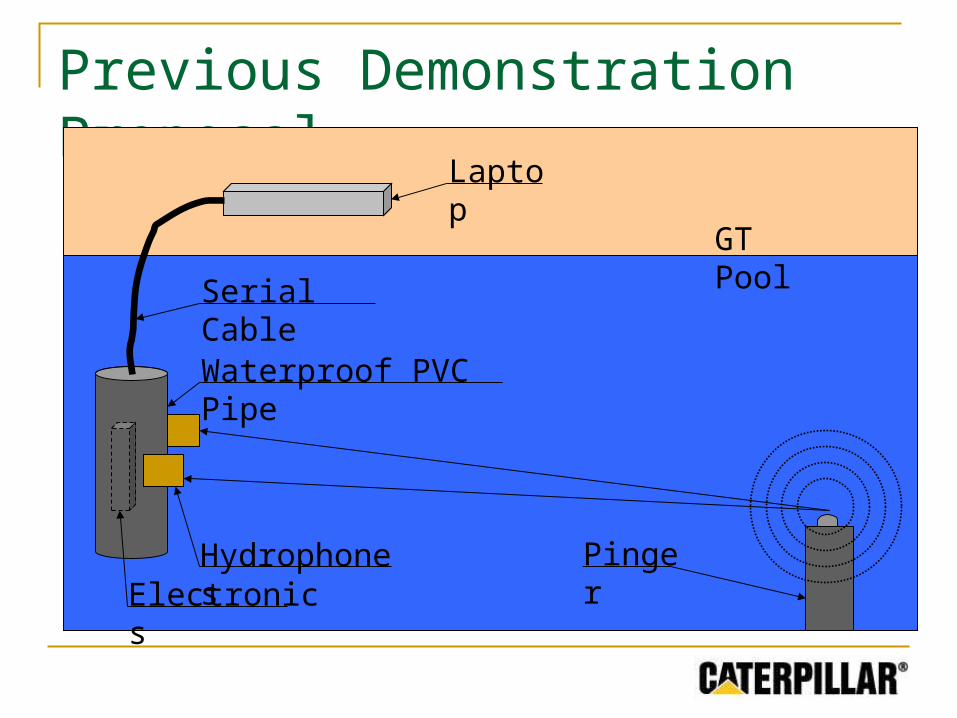
Previous Demonstration Proposal
Hydrophones
Waterproof PVC Pipe
Pinger
GT Pool
Laptop
Serial Cable
Electronics
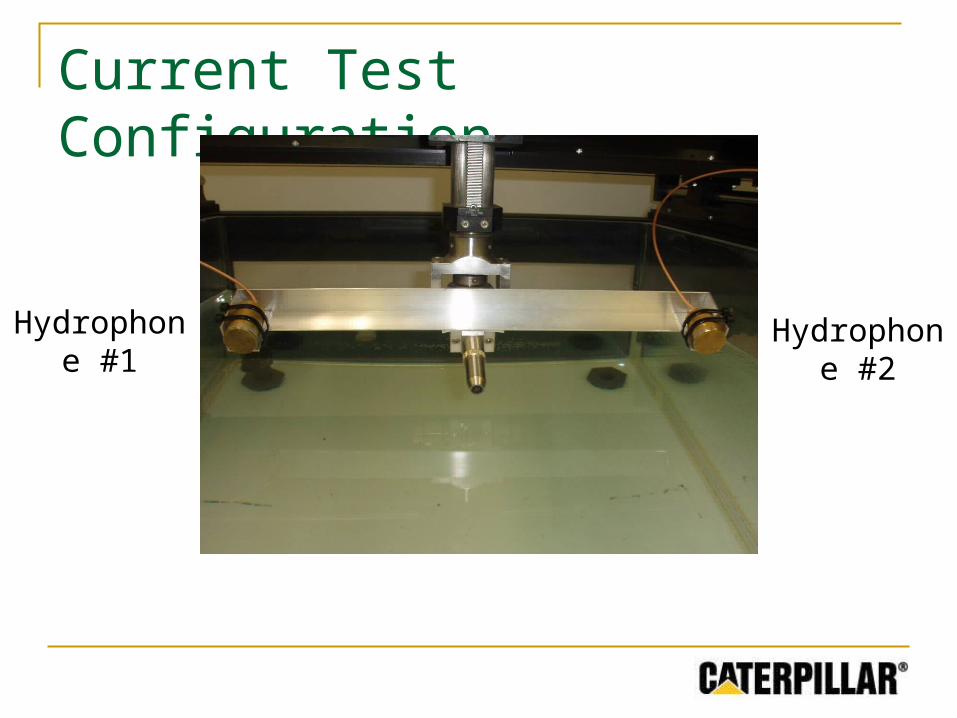
Current Test Configuration
Hydrophone #1
Hydrophone #2
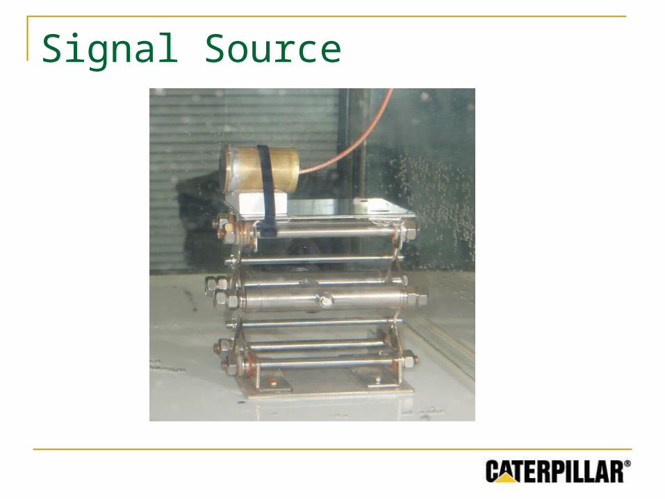
Signal Source
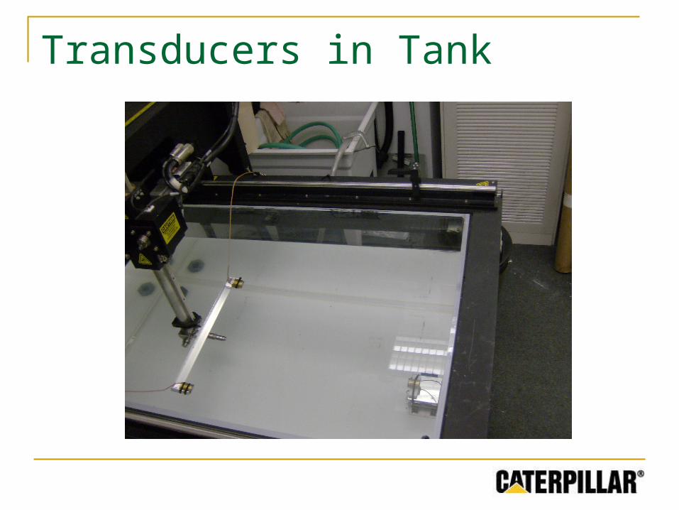
Transducers in Tank
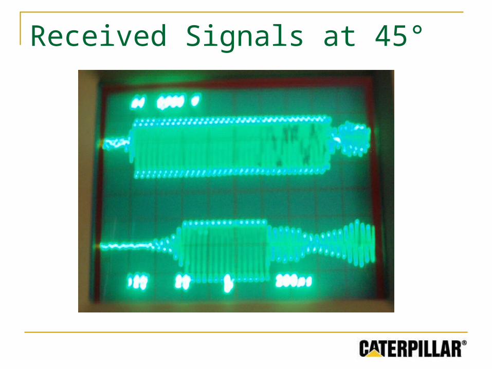
Received Signals at 45°
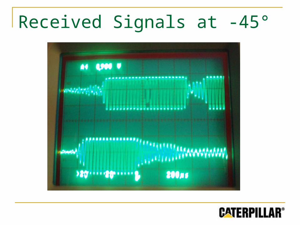
Received Signals at -45°
Remaining Work
Complete amplifier on solder board Complete power supply circuit Eliminate reflections for demonstration
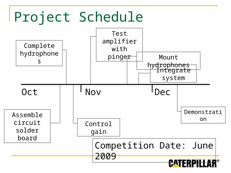
Dec
Project Schedule
Oct Nov
Test amplifier with pinger
Control gain
Demonstration
Competition Date: June 2009
Mount hydrophones
Assemble circuit solder
board
Complete hydrophones
Integrate system