direction finding antenna - lstelcom.com · technology, called df time travel® that allows...
TRANSCRIPT

Radio Monitoring
Direction Finding Antenna LS OBSERVER AOA 100DF Time Travel®
www.LStelcom.com
NEXT GENERATION DIRECTION FINDING AOA 100
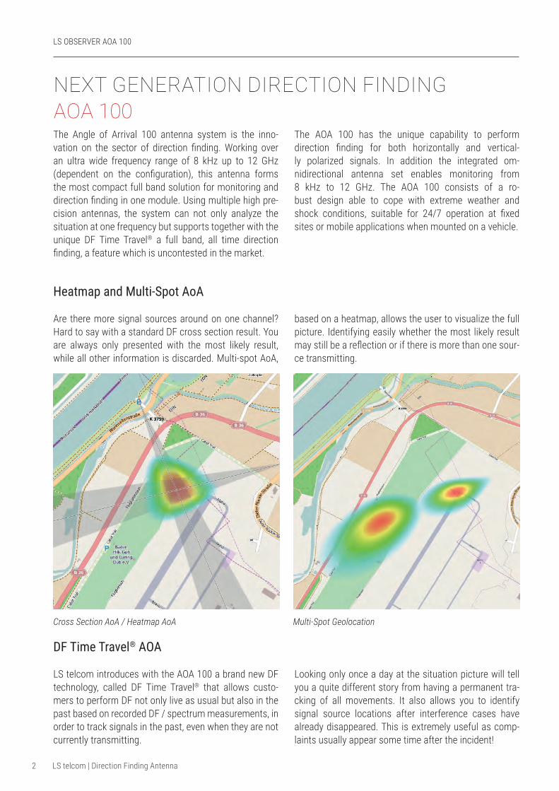
Cross Section AoA / Heatmap AoA Multi-Spot Geolocation
The Angle of Arrival 100 antenna system is the inno-vation on the sector of direction finding. Working over an ultra wide frequency range of 8 kHz up to 12 GHz (dependent on the configuration), this antenna forms the most compact full band solution for monitoring and direction finding in one module. Using multiple high pre-cision antennas, the system can not only analyze the situation at one frequency but supports together with the unique DF Time Travel® a full band, all time direction finding, a feature which is uncontested in the market.
The AOA 100 has the unique capability to perform direction finding for both horizontally and vertical-ly polarized signals. In addition the integrated om-nidirectional antenna set enables monitoring from 8 kHz to 12 GHz. The AOA 100 consists of a ro-bust design able to cope with extreme weather and shock conditions, suitable for 24/7 operation at fixed sites or mobile applications when mounted on a vehicle.
Heatmap and Multi-Spot AoA
Are there more signal sources around on one channel? Hard to say with a standard DF cross section result. You are always only presented with the most likely result, while all other information is discarded. Multi-spot AoA,
based on a heatmap, allows the user to visualize the full picture. Identifying easily whether the most likely result may still be a reflection or if there is more than one sour-ce transmitting.
LS OBSERVER AOA 100
2 LS telcom | Direction Finding Antenna
DF Time Travel® AOA
LS telcom introduces with the AOA 100 a brand new DF technology, called DF Time Travel® that allows custo-mers to perform DF not only live as usual but also in the past based on recorded DF / spectrum measurements, in order to track signals in the past, even when they are not currently transmitting.
Looking only once a day at the situation picture will tell you a quite different story from having a permanent tra-cking of all movements. It also allows you to identify signal source locations after interference cases have already disappeared. This is extremely useful as comp-laints usually appear some time after the incident!

Full Band AoA
Do you know which band segment may be of interest later-on? No problem with our innovative full-band AoA! The user selects only the band of interest, which may be one channel, 1 MHz or everything from 8 kHz to 12 GHz. The system will record and store the informa-tion for up to 30 days even for the full band*. It allows to look at what did happen in the past, not only at one channel or in the real-time bandwidth, but also in the complete DF band. The system allows, based on the stored data to carry out all of the analysis like DF Time Travel® AoA, heatmaps and multi-spot direction finding.
DF Time Travel®
* Subject to version of LS OBSERVER
LS OBSERVER TMU (Transportable Monitoring Unit) Ideal for temporary mobile and fixed measurements, battery powered
LS OBSERVER FMU (Fixed Monitoring Unit) Ideal for continuous measurements /long-term installation, to cover a large range of frequencies
LS OBSERVER PPU (Protected Portable Unit) Ideal for portable, mobile and temporary fixed measurements in rough environments.
LS OBSERVER PMU (Portable Monitoring Unit) Ideal for handheld, portable and mobile applications; for ad-hoc measurements
LS OBSERVER AMU(Airborne Measurement Unit) RF & antenna pattern measurements, site inspection and airborne monitoring using Remotely Piloted Aircraft (RPA)
3LS telcom | Direction Finding Antenna
Member of the LS telcom Group
START END
Turn back time... ...and see, ...what really happened.
ü Monitoring and DF with one single antenna system
ü Large frequency range
ü DF horizontally and vertically polarized signals
ü Monitoring and DF in parallel
ü DF signals in the past
ü Fixed and mobile usage
Key characteristics

TECHNICAL DETAILS A0A 100
4 LS telcom | Direction Finding Antenna
AOA 100 AOA 110 AOA 120RF Characteristics – Direction Finding Antenna Set
Set-Up Multi-Layer – Multi Directional – Array
Frequency Range 8 kHz - 12 GHz 20 MHz - 8 GHz 300 MHz - 6 GHz
Impedance Nominal 50 Ohm
Location Methode DF TimeTravel®
Polarisation Horizontal and Vertical
RF Characteristics – Monitoring Antenna Set
Set-Up Array of Monopole and Discone
Frequency Range 8 kHz - 12 GHz 8 kHz - 8 GHz 8 kHz - 6/8/12 GHz***
Impedance Nominal 50 Ohm
Directivity Omnidirectional
Polarization Vertical
Gain Typical 0 to -20 dBi above 1 MHz dependent on frequency
Connecitivity
RF 2 x N connector female
Control Multi-Purpose Serial connector
Power 5/12 VDC
Mechanical Flange Adapter with 8xM8
Mechanical Characteristics
Diameter 1790 mm
Height 890 mm 890 mm 590 mm
Weight 49 kg 46 kg 39 kg
Environmental Characteristics
Wind Speed Operational 100 km/h
Wind Speed Survival 180 km/h
Operation Temperature -20 to 55 °C
Storage Temperature -40 to 70 °C
Humidity 0 to 100 %
Protection Class IP55/65/67, dependent on version
AOA120 VHF1 Extends DF Frequency Range of AoA 120 down to 88 MHz *
AOA120 VHF2 Extends DF Frequency Range of AoA 120 down to 20 MHz **
AOA120 HF Extends DF Frequency Range of AoA 120 down to 500 kHz **
AOA120 LF Extends DF Frequency Range of AoA 120 down to 8 kHz **
AOA120 SHF1 Extends DF Frequency Range of AoA 120 up to 8 GHz*
AOA120 SHF2 Extends DF Frequency Range of AoA 120 up to 12 GHz*
Upgrades
For further information, please visit our website www.LStelcom.com or contact [email protected].
* Weight may be increased ** Weight and height may be increased *** Dependent on AoA upgrade