direct heat
TRANSCRIPT
DIRECT HEAT
P. J. Lienau
OIT Geo-Heat CenterKlamath Falls, Oregon 97601
Prepared for GRC Introduction toGeothermal Resources, March 1990
ABSTRACT
Potential resources and applications of earth heat in the form of geothermal energy are large. United Statesdirect uses amount to 2,100 MWt thermal and worldwide 8,850 MWt above a reference temperature of 35oC.Space and district heating are the major direct uses of geothermal energy. Equipment employed in direct useprojects is of standard manufacture and includes downhole and circulation pumps, transmission and distributionpipelines, heat exchangers and convectors, heat pumps and chillers. Direct uses of earth heat discussed are spaceand district heating, greenhouse heating and fish farming, process and industrial applications. The economicfeasibility of direct use projects is governed by site specific factors such as location of user and resource, resourcequality, system load factor and load density, as well as financing. Examples are presented of district heating inKlamath Falls, and Elko. Further developments of direct uses of geothermal energy will depend on matching userneeds to the resource, and improving load factors and load density.
INTRODUCTION
The technology of direct uses is in general well established. When viewed in terms of local and site specificconditions, however, this may not always appear to be the case. In many instances, there are institutional, legal,and environmental concerns that prevent the building of technically feasible direct use projects. A familiartechnical solution such as fuel oil or electrical heating is often more acceptable than the less common geothermaloption. Furthermore, the risk involved in buying fuel oil seems less than drilling for hot water for heating. Thedriving force of most direct use projects, however, is the economic advantage over alternative energy sources.In some instances, the advantages is there--in others not.
The purpose of this paper is to identify the principal elements of direct uses of geothermal energy. Localissues affecting the overall feasibility of direct use projects are not discussed, except perhaps incidentally. Thepaper concerns the technologies needed to bring geofluids from resource to user.
POTENTIAL
Tremendous potential exists in the United States for the development of geothermal energy. The low- andintermediate-temperature (<90 to 150oC) geothermal resource base as reported in Muffler, 1978 and Reed, 1983,is estimated at 26,500 Quads. It is estimated that the wellhead thermal energy recoverable from these resourcesis 302 Quads.
Low-temperature geothermal resources occur in two types of geothermal systems--hydrothermal convectionand conduction dominated, which are quantified in Table 1.

Table 1. Thermal Energy from Low-to-Intermediate Temperature Identified Geothermal Systems in the United States.a
_________________________________________________________________________________________ Resource Resourceb
Temperature Base Resourcec
System (oC) No Systems x 1015 Btu x 1015 Btu
Hydrothermal-Convection <90 1,123 190 30
90 to 150 163 660 167
Conduction-Dominated to 3 km <90 38 25,690 105 1,324 26,500 302______________________________________________a. Reed, 1983 and Muffler, 1978.b. Resource base - geothermal energy in the ground.c. Resource - energy that might be recoverable at the wellhead._______________________________________________________________________________________
In hydrothermal-convection systems, upward circulation of water transports thermal energy to reservoirs atshallow depths or to the surface. These systems commonly occur in regions of active tectonism and above-normalheat flow, such as much of the western United States. In conduction-dominated systems, there exists high verticaltemperature gradients in rocks that include aquifers of significant lateral extent. These conditions occur beneathmany deep sedimentary bases throughout the United States (Reed, 1983).
The location of geothermal resources plays an important role in their applications. In the case of geothermalelectric power plants, this aspect of feasibility is clear and all such plants are built at the resource site. In the caseof district heating, however, this aspect of feasibility is less clear. Nevertheless, a geothermal resource withina town is more likely to be used than a distant resource. The co-location of a resource and a user becomes lessimportant when energy costs dominate the feasibility of project. In Iceland, for example, where space heatingmust be used for most of the year, geothermal waters are being piped longer and longer distances.
District heating systems have received increasing attention in the United States in the past few years. Aninventory identified a total of 1,277 hydrothermal sites within five miles of 373 cities in eight western states, witha combined population of about 6 - 7 million people (Allen, 1980). The total heat load of these cities (exclusiveof industrial use) is estimated at 173,000 x 1099 Btu/yr. In terms of installed thermal power this amount of energycorresponds to 15,000 MW, when assuming a load factor of 30%.
Energy Use Distribution
Compared with thermal energy from the combustion of conventional fossil fuels, geothermal energy resourceshave a much lower temperature. Temperatures of the order of 1500oC are readily attained in combustion, and thisresults in common working fluid and process temperatures of 500 to 1000oC. On the other hand, the highestknown temperatures of workable geothermal resources are of the order of 250oC. These differences intemperature are critical inputs for evaluating how geothermal energy can best be used (Reistad, 1975).
Three main factors make direct applications have a significant potential in geothermal energy use. First,although electricity generation is technically feasible at low-to-moderate temperatures, there is a definite economiclimit on the resource temperatures suitable for power generation. Secondly, the supplying of low-to-moderatetemperature heating from high-grade fossil fuels results in poor thermodynamic performance. Matchinggeothermal resources to meet these heating requirements would result in much better use of worldwide energyresources. Thirdly, it appears that a large portion of the basic energy needs of modern industrial society is forlow-to-moderate temperature heating.

The amount of direct heating that could be used to meet the basic energy requirements of an industrializednation, and the temperatures that are required for such heating, were estimated by Reistad (1975). Although thedata used are now out-of-date, the same trends in energy use distribution are likely to be exhibited by more recentinformation. An upper temperature limit of 250oC was assumed for potential geothermal energy applications.All energy used in the United States below this temperature limit were estimated in 25oC temperature ranges from50 to 250oC. It was found that a substantial amount of the total energy was used below 120oC. Space heatingat 50 to 75oC application temperature was by far the largest single use, representing almost 50 percent of the totalat temperatures below 250oC. The results of Reistad (1975) are shown schematically in Figure 1, which illustratesthe fractional energy use distribution with temperature (Tester, 1982). The thermal applications used to constructthis figure represent 40 percent of the total energy consumption in the United States at the time. The relationshipbetween resource and user was not considered in the Reistad (1975) study. However, it demonstrates the largepotential for direct uses of geothermal energy, provided the resource and user are geographically matched.
Figure 1. Energy use distribution with temperature.
SURVEY
Direct heat use of geothermal energy in the United States is recognized as one of the alternative energyresources that has proven itself technically and economically, and is commercially available. Developmentsinclude space conditioning of buildings, district heating, geothermal heat pumps, greenhouse heating, industrialprocessing, aquaculture, and swimming pool heating. Forty-five states have experienced significant geothermaldirect use development in the last ten years. The total installed capacity is 7.2 billion Btu/hr (2,100 MWt), withan annual energy use of over 18,000 billion Btu/yr (5 million barrels of oil energy equivalent). These data arebased on an extensive site data gathering effort by the Geo-Heat Center in the spring of 1988, under contract tothe U.S. Department of Energy (Lienau, 1988). These energy use values are graphically displayed in Figure 2,showing the significant increase in the use of geothermal energy for direct use, especially after 1970. The annualcompound growth rate for the industry from 1940 to 1970 was about 3%, from 1970 to 1985 about 13% and from1985 to 1990 it is estimated at 6%. Of course the oil price shocks of the early 1970s and federal incentivesaccount for the increase during the 1970 to 1985 period.
Figure 3 shows the projects on-line, separating heat pump installations from the other direct use applications.Most people think of geothermal energy as a western states resource; however, there are significant projectsdeveloping this resource for space conditioning and district heating where low temperature (40 to 70oF)groundwater aquifers exist throughout the entire United States. Groundwater and earth coupled (vertical

configuration) heat pump systems depend upon the average groundwater temperature. The recent phenomenaof heat pump installations expects a growth rate of about 50 percent per year through 1990, according to the heatpump industry. Approximately 66,100 groundwater heat pump installations are presently installed.
Figure 2. Direct use energy on-line Figure 3. Direct use projects on-line from 1940 to 1990. between 1940 and 1990.
Table 2 gives the distribution of use according to application and Figure 4 shows the location of direct heatprojects. The largest single application, the secondary oil recovery operations are in Montana, North Dakota,South Dakota and Wyoming.
Table 2. United States Geothermal Use by Application in 1990________________________________________________________________________________________
Capacity Annual EnergyApplication No. of Sites (106 Btu/hr) (109 Btu/yr)
Space and District Heatinga,b 121 560.4 1,476.3Geothermal Heat Pumpsa 147 3,875.0 5,346.0Greenhouses 36 163.1 396.0Aquaculture 18 223.9 1,179.8Resorts/Pools 114 233.5 1,452.3Industrial 12 99.8 402.8
Enhanced Oil Recovery 4 1,163.9 8,156.2 7,196.6 18,409.4
___________________________________
a. Includes Klamath Falls residential downhole heat exchanger systems (550), schools (7), apartment buildings(13), churches (4) and Reno/Moana residential downhole heat exchangers (300).
b. Two systems reported under construction, Mammoth Lakes (117 x 109 Btu/y) and Bridgeport (14.2 x 10⁹
Btu/y). The city of Klamath Falls systems is undergoing reconstruction of the distribution piping._______________________________________________________________________________________

Figure 4. Location of direct heat projects in the United States.
EQUIPMENT
Standard equipment is used in most direct-use projects, provided allowances are made for the nature ofgeothermal water and steam. Temperature is an important consideration; so is water quality. Corrosion andscaling caused by the sometimes unique chemistry of geothermal fluids, may lead to operating problems withequipment components exposed to flowing water and steam. In many instances, fluid problems can be designedout of the system. One such example concerns dissolved oxygen, which is absent in most geothermal waters,except perhaps the lowest temperature waters. Care should be taken to prevent atmospheric oxygen from enteringdistrict heating waters--for example, by proper design of storage tanks. The isolation of geothermal water byinstalling a heat exchanger may also solve this and similar water quality derived problems. In this case, a cleansecondary fluid is then circulated through the used side of the systems.
The primary components of most low-temperature direct use systems are downhole and circulation pumps,transmission and distribution pipelines, heat exchangers, and various forms of heat extraction equipment. Fluiddisposal is either surface or subsurface (injection). A peaking system may be necessary to meet maximum load.This can be done by increasing the water temperature or by providing tank storage. Both options mean that fewerwells need to be drilled. When the geothermal water temperature is warm (below 50oC) heat pumps are oftenused. The equipment used in direct use projects represent several units of operation. The major units will nowbe described in the same order as seen by geothermal waters produced for district heating.

Downhole Pumps
Direct-use production wells consist of three main parts: surface casing (pump housing), the inlet portion, andthe production casing between them. Surface casing diameter is usually two nominal pipe sizes larger than thepump bowls. For example, a production rate of 350 to 700 gpm requires an 8-in. diameter pump and a nominalsurface casing diameter of 12 in.
The production well pumps are vertical lineshaft turbines with fluid coupling type variable speed drive unitsas shown in Figures 5 and 6. The variable speed drive provides for continuous operation of the pump to provideconstant pressure at the wellhead and in the supply line under varying flow requirements. Pump dischargepressure is monitored by the fluid coupling control, which changes turbine shaft speed to maintain constantdischarge pressure from no-low to full-flow conditions and eliminates the need for storage tanks required withintermittent pump operation. The actual design of the pumps evolved over the initial 16 years of operating theOIT geothermal heating system.
Figure 6. Fluid coupling (Culver and Rafferty, 1989).
In 1964, at OIT, direct-drive lineshaft vertical turbine pumps were originally installed with electric motorsin 5 ft pits; this resulted in overheating of the motors. Open lineshaft water lubricated bearings, spaced at 10 ftintervals, developed problems due to hot water vaporizing in the bearing housing causing them to burn out.
In 1970, the pump system design was modified by adding variable speed fluid coupling drives, extending themotor to the surface for ventilation and using an oil lubricated enclosed lineshaft. The 13-stage pump was setat 450 ft in the 1,716 ft OIT Well No. 5, where the static water level was 358 ft below the surface. The pump wascustom designed for a 5 in. differential expansion (lateral) between the lineshaft and the column. The start-upprocedure is to lower the shaft to the bottom then raise it 5 in. to allow for expansion during the time to reachthermal equilibrium.

Figure 5. Typical lineshaft turbine pump with an enclosed oil-lubricated shaft (Culver and Rafferty, 1989).
The following materials, which have performed satisfactorily, are used for pump construction:
Bowl Bearings ImpellerColumn Bowls and Impellers Pump Shaft Lock Collets
ASTM A53 ASTM A48 ASTM 584 Type 416 SS Type 316 SSGrade A Class 35 Alloy UNS Gray iron Leaded red bronze
Turbine oil No. 68 is used for lineshaft lubrication.
Since 1970, the only serious problem has been with the main thrust bearing in the driver. This bearing hashad to be replaced four times at a cost of about $1,200 per replacement. The column in No. 5 was replaced after25 years of operation due to corrosion. Oxygen is prevented from contacting the inside of the column bymaintaining a back-pressure with the variable speed drive. Start-stop modes of operation caused serious corrosionproblems, with the introduction of oxygen, such as that experienced by the neighboring hospital well.
The life of the OIT vertical turbine pumps has been over 20 years and the design developed has been the basisfor other installations.
Transmission and Distribution
The fluid state in transmission lines of direct use projects can be liquid water, steam vapor or a two-phasemixture. These pipelines carry fluids from the wellhead to either a site of application, or a steam-water separator.The temperatures the various transmission lines experience can range from ambient to about 200oC. Thermalexpansion of pipelines heated rapidly from ambient to geothermal fluid temperatures causes stress that must beaccommodated by careful engineering design. In low-temperature applications the thermal stress is less butnevertheless significant. The collection and transmission of geothermal fluids has been discussed by Rafferty(1989). The design principles adopted for geothermal steam and hot water lines are the same as used inconventional power and district heating systems.
The cost of transmission lines and the distribution networks (Figure 7) in direct use projects is significant.This is especially true when the geothermal resource is located at great distance from the main load center. Alldistrict heating systems have a distribution network. Although engineers have developed standard designs forhot water distribution in towns and cities, that holds less true for transmission lines. Therefore, many types oftransmission lines are found in geothermal applications.
Carbon steel is the most widely used for geothermal transmission lines and distribution networks. Individualsystems tend to differ in the form of insulation. Conventional steel piping requires expansion provisions, eitherbellows arrangements or by loops. A typical piping installation would have fixed points and expansion pointsabout every 300 ft. In addition, the piping would have to be placed on rollers or slip plates between points. Whenhot water pipelines are buried they can be subjected to external corrosion from groundwater and electrolysis.They must be protected by coatings and wrappings. Concrete tunnels or trenches have been used to protect steelpipe in many geothermal district heating systems. Although expensive, tunnels and trenches have the advantageof easing future expansion and access for maintenance.
Supply and distribution systems can consist of either a single-pipe or a two-pipe system. The single-pipe isa once-through system where the fluid is disposed of after use. This distribution system is generally preferredwhen the geothermal energy is abundant and the water is pure enough to be circulated through the distributionsystem. In a two-pipe system the fluid is recirculated so the fluid and residual heat are conserved. A two-pipesystem must be used when mixing of spent fluids is called for, and when the spent cold fluids need to be injectedinto the reservoir. Two-pipe distribution systems cost typically 20 to 30 percent more than single-piped systems.

Figure 7. Pipe material costs (1989) for nominal 6 in. diameter.
Figure 8. Temperature drop in flowing water (Ryan, 1981).
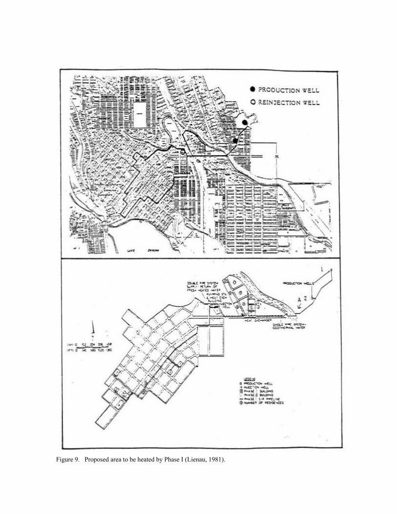
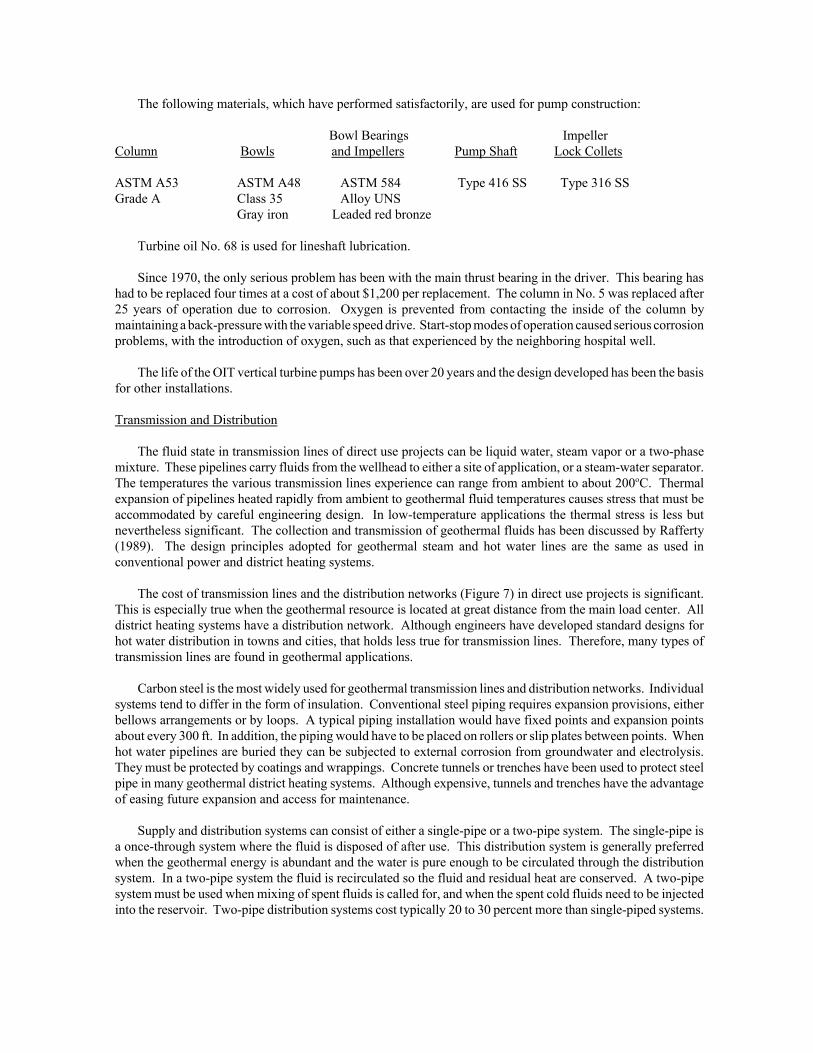
Figure 9. Proposed area to be heated by Phase I (Lienau, 1981).
\ -.. , • • "., . < -~
• •
• ?ROOUCTION '¥I!:~ ~
o "EIN:lECTION 'J'EL~
= .-. ........ • ...". ".-<0. ~h .. E" ......., . ~ .... ----.~ , , .. .... .. $ ...-. .......... ,

The quantity of thermal insulation of transmission lines and distribution networks will depend on many factors.In addition to minimizing the heat loss of the fluid, the insulation must be waterproof and water tight. Moisturecan destroy the value of any thermal insulation, and caused rapid external corrosion. Above ground and overheadpipeline installations can be considered in special cases. Considerable insulation is achieved by burying hot waterpipelines. For example, burying bare steel pipe results in a reduction in heat loss of about one third as comparedto above ground in still air. If the soil around the buried pipe can be kept dry, then the insulation value can beretained. Carbon steel piping can be insulated with polyurethane foam and fiberglass. Below ground, such pipesshould be protected with a polyvinylchloride jacket; above ground aluminum can be used. Generally, one to threeinches of insulation is adequate.
At flowing conditions the temperature loss in insulated pipelines is in the range 0.5oF/1000 ft. Pipe materialdoes not have a significant effect on heat loss. However, the flow rate does have a significant effect. At low flowrates (off peak) the heat loss is higher than at greater flows. This aspect of geothermal pipeline design is illustratedin Figure 8. It shows the temperature loss as a function of the flow in a 6-in. pipe.
Several types of hot water transmission are used in the 22 geothermal district heating systems in the UnitedStates; some of these are discussed by Rafferty (1988).
A layout of the Klamath Falls distribution system appears in Figure 9. This system consists of two majorportions: transmission line and distribution loop.
A description of the system, from Rafferty, 1989, follows:
"The transmission line employs two types of installation methods: direct buried and concrete tunnel. Theentire 4,400 ft length is composed of 8-in. pre-insulated, Schedule 40 steel piping with a fiberglass jacket.From the production wells to Point A (Figure 9), this line is direct buried (Figure 10). Expansion jointsare of the controlled flexing type with 304 SS carrier. After the passing under a state highway and acrossa canal bridge, the line enters the concrete tunnel. The tunnel is located for the most part under a sidewalkand was designed to accommodate a second 8-in. transmission line to provide for system growth (Figure11).
All of the secondary loop is direct-buried piping. Approximately 4,400 ft of the total is 10-in. pre-insulated, Schedule 40 steel similar to the transmission line. Sizes less than 10 in. (8,280 ft) are pre-insulated FRP piping of the key-lock type mechanical joining.
A problem encountered with the city system was a failure of the joining system used on the fiberglasspiping in the secondary loop. A detail of a typical joint is shown in Figure 12.
The failure of the system was the result of the lock ring portion of the joint becoming detached from thepiping. The lock rings were attached, by the manufacturers, with an epoxy adhesive. This adhesive wasevidently improperly manufactured or applied. In any case, failure of the epoxy permitted axial movementin the joint. Eventually resulting in leaks at these locations. The existing fiberglass material will bereplaced entirely with ductile iron when the city secures funding for the construction."
Heat Exchangers
The principal heat exchangers used in geothermal systems are the plate, shell-and-tube, and downhole types.The plate heat exchanger consists of a series of plates with gaskets held in a frame by clamping rods (see Figure13). The gasket material limits the maximum temperature that can be used. The primary and secondary fluids areusually passed through alternating passages between the plates in single-pass counter-flow, although other flowpaths can usually be arranged by simple external piping. Stamping of the plates provides a variety of flow-pathpatterns. The counter-current flow and high turbulence achieved in plate heat exchangers, provide for efficientthermal exchange in a small volume. Plate heat exchangers are commonly used in geothermal heating situationsworldwide. The plates are usually made of stainless steel, although titanium is used when the fluids are especially

Figure 10. Steel pipe with polyurethane insulation and polyethylene cover.
Figure 11. Tunnel construction detail (Lund an Lienau, 1980).
Figure 12. "Kwikey" connection system detail (Rafferty, 1989).
corrosive; for example, in several of the district heating systems in France. Plate heat exchangers are about 60percent of the costs of shell-and-tube exchangers when compared at the same surface area (Ryan, 1981).
The plate heat exchanger is generally considered superior to the tube and shell type in application forgeothermal liquid-to-liquid heat transfer where close approach temperatures are desirable and plate materials otherthan mild steel are required for corrosion resistance. They require little floor space, are easily cleaned, and aremuch more efficient. Of particular importance is the ease of changing exchanger surface area to accommodatechanges in flow and temperature conditions by adding or removing plates.
Conventional shell-and-tube heat exchangers may be used for geothermal applications. This type of exchangeris readily available or may be custom designed to meet a specific need. Shell-and-tube exchangers consist of aseries of tubes, normally carrying the geothermal water, surrounded by an enclosing shell, confining the secondarysystem water around the tubes. The tubes in this type of exchanger can be a U-tube configuration or a straight tubewith removable heads at both ends to facilitate cleaning of the tubes.
About 1930, the first downhole heat exchanger (DHE), was installed in a geothermal well in Klamath Falls.The heat exchanger coil consists of two strings of pipe connected at the bottom by a reverse bend. The temperatureof the well water and the predicted heat load determine the length of the pipe required. Based on experience, localheating system contractors estimate approximately "one foot of coil per 1,500 Btu per hour" required. The coilpipes are connected to the supply and return of the distributing piping and the entire system filled with city water.

Figure 13. The plate heat exchanger (Culver and Rafferty, 1989).
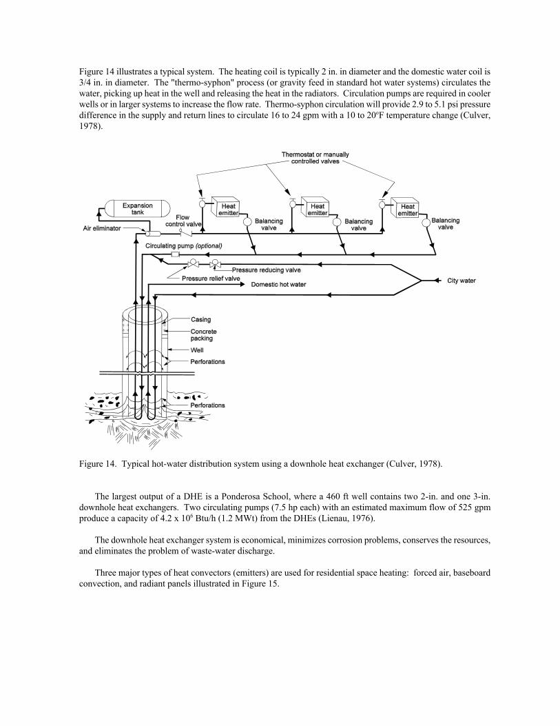
Figure 14 illustrates a typical system. The heating coil is typically 2 in. in diameter and the domestic water coil is3/4 in. in diameter. The "thermo-syphon" process (or gravity feed in standard hot water systems) circulates thewater, picking up heat in the well and releasing the heat in the radiators. Circulation pumps are required in coolerwells or in larger systems to increase the flow rate. Thermo-syphon circulation will provide 2.9 to 5.1 psi pressuredifference in the supply and return lines to circulate 16 to 24 gpm with a 10 to 20oF temperature change (Culver,1978).
Figure 14. Typical hot-water distribution system using a downhole heat exchanger (Culver, 1978).
The largest output of a DHE is a Ponderosa School, where a 460 ft well contains two 2-in. and one 3-in.downhole heat exchangers. Two circulating pumps (7.5 hp each) with an estimated maximum flow of 525 gpmproduce a capacity of 4.2 x 10⁶ Btu/h (1.2 MWt) from the DHEs (Lienau, 1976).
The downhole heat exchanger system is economical, minimizes corrosion problems, conserves the resources,and eliminates the problem of waste-water discharge.
Three major types of heat convectors (emitters) are used for residential space heating: forced air, baseboardconvection, and radiant panels illustrated in Figure 15.

Figure 15. Convectors: (a) forced air, (b) baseboard finned tubed, and (c) radiant panel.
All can be adapted directly to geothermal or converted by retrofitting existing systems. Retrofitting existingsystems may require larger fan coil units or additional baseboard convectors if the fossil fuel system required a highdesign temperature (above 200oF) or the geothermal fluid has a low temperature (generally below 150oF)(Lund,1978). The details of each type of system are as follows:
Forced air. This system heats the incoming cold air by finned tube hot water coils and then distributes theheated air to the residence by ductwork to vents, usually located on outside walls. These units caneconomically use fluids of 120oF and higher with temperatures above 160oF being most efficient. Onemajor advantage of forced air systems is the ability to incorporate air conditioning at a small additionalcost. Retrofit would normally only require the placement of the finned tube hot water coil in the plenumof an electric or gas forced air furnace. The distribution system (ductwork) would not have to be modified.
Baseboard convection. This system uses hot water as the heat transfer medium where the hot water isdistributed to convector units located at the base of outside walls. Fins attached to the piping transfer theheat to the room by means of natural convection. These units are economical above 140oF with above160oF being the best range. The efficiency of the unit can be increased to use lower temperature water byplacing a fan behind the unit to help circulate the air. Depending upon the temperature, retrofitting thesystem would require additional units or lengthening existing units.

HEAT EXCHANGERREFRIGERANT / AIR
(CONDENSER)
COOL RETURN AIRFROM CONDITIONED
SPACE
EXPANSION VALVE
REFRIGERANTREVERSING VALVE
WARM SUPPLY AIR TOCONDITIONED SPACE
HEAT EXCHANGERREFRIGERANT / WATER
(EVAPORATOR)
TO / FROM GROUNDHEAT EXCHANGER
(GEOTHERMAL)
REFRIGERANTCOMPRESSOR
DOMESTIC HOT WATEREXCHANGER
(DESUPERHEATER)
DOMESTIC WATER
INOUT
HEAT EXCHANGERREFRIGERANT / AIR
(EVAPORATOR)
WARM RETURN AIRFROM CONDITIONED
SPACE
EXPANSION VALVE
REFRIGERANTREVERSING VALVE
COOL SUPPLY AIR TOCONDITIONED SPACE
HEAT EXCHANGERREFRIGERANT / WATER
(CONDENSER)
TO / FROM GROUNDHEAT EXCHANGER
(GEOTHERMAL)
REFRIGERANTCOMPRESSOR
DOMESTIC HOT WATEREXCHANGER
(DESUPERHEATER)
DOMESTIC WATER
INOUT
Radiant panels. This system is located in floors, walls or ceilings and radiate heat to the room. Hot wateris circulated in coils of pipe (usually plastic or copper) imbedded in concrete or plaster. Their mainadvantage is the uniform heat provided without a draft and the lower temperature fluid that can be used.Use of fluid temperatures as low as 100oF is possible. The main disadvantage of this system is that it isdifficult and expensive to repair if problems develop (especially leaks). This method is popular in garageand basement floors, and for melting snow on driveways and sidewalks.
Circulation pumps. Natural thermal convection is often adequate to provide water circulation in heatingsystems, especially those with downhole heat exchangers. A circulation pump may be required in theheating system to increase the flow of the fluid through the heat convector (to increase the heat transferrate). This may be necessary for low-temperature geothermal fluids or in extremely cold weather. It willbe mandatory when two or more residences share the same well to balance the heat load. Generally, apump from 1/6 to 1/2 horsepower will be adequate.
Controls. Thermostatically controlled valves are desirable to control the heat within a residence. This isespecially important with zoned heating systems, where each zone will have a thermostat.
Geothermal Heat Pumps
Like refrigerators, heat pumps operate on the basic principle that fluid absorbs heat when it evaporates into agas, and likewise gives off heat when it condenses back into a liquid. A geothermal heat pump system can be usedfor both heating and cooling, as shown in Figures 16 and 17. In the heating mode, the evaporator acts as the heatexchanger transferring heat to the refrigerant. The refrigerant is then compressed, which changes it into a hotvapor. The hot vapor is then passed through a condenser, or the space conditioning heat exchangers, where the heatis transferred to air or water for space heating. At this point, the vapor changes to a warm liquid which is thenpassed through an expansion valve changing it to a cool liquid/vapor mixture to start the cycle over again. In thecooling mode (see Figure 17), the direction of flow of the refrigerant reverses. The refrigerant is a material suchas freon, isobutane, that has a boiling point close to -0.4oF. External energy is needed to operate the compressor,fans and hot water pumps.
Figure 16. Heating cycle (source Oklahoma State Figure 17. Cooling cycle (source Oklahoma State University). University).
Two major types exist: earth coupled or water source. The earth coupled uses a buried earth coil withcirculating fluid in a closed loop of horizontal or vertical pipes to transfer thermal energy to and from the earth.The water source uses a well or an open pond to provide an energy source or sink. Earth coupled systems havebeen used in northern Europe for many years, but were not used on a commercial scale in the U.S. until 1980.Earth coupling is used where insufficient well water is available, where the quality of well water is a problem,where drilling and casing of wells are expensive, or where disposal of well water is restricted.
4'
6'
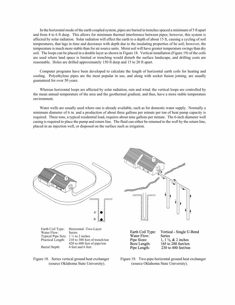
Earth Coil Type: Horizontal -Two-LayerWater Flow: SeriesTypical Pipe Size: 1 ½ to 2 inchesPractical Length: 210 to 300 feet of trench/ton
420 to 600 feet of pipe/tonBurial Depth: 4 feet and 6 feet
In the horizontal mode of the earth coupled system, pipes are buried in trenches spaced a minimum of 5 ft apartand from 4 to 6 ft deep. This allows for minimum thermal interference between pipes; however, this system isaffected by solar radiation. Solar radiation will effect the earth to a depth of about 15 ft, causing a cycling of soiltemperatures, that lags in time and decreases with depth due to the insulating properties of he soil; however, thetemperature is much more stable than for air source units. Moist soil will have greater temperature swings than drysoil. The loops can be placed in a double layer as shown in Figure 18. Vertical installation (Figure 19) of the coilsare used where land space is limited or trenching would disturb the surface landscape, and drilling costs arereasonable. Holes are drilled approximately 150 ft deep and 15 to 20 ft apart.
Computer programs have been developed to calculate the length of horizontal earth coils for heating andcooling. Polyethylene pipes are the most popular in use, and along with socket fusion joining, are usuallyguaranteed for over 50 years.
Whereas horizontal loops are affected by solar radiation, rain and wind; the vertical loops are controlled bythe mean annual temperature of the area and the geothermal gradient, and thus, have a more stable temperatureenvironment.
Water wells are usually used where one is already available, such as for domestic water supply. Normally aminimum diameter of 6 in. and a production of about three gallons per minute per ton of heat pump capacity isrequired. Three tons, a typical residential load, requires about nine gallons per minute. The 6-inch diameter wellcasing is required to place the pump and return line. The fluid can either be returned to the well by the return line,placed in an injection well, or disposed on the surface such as irrigation.
Figure 18. Series vertical ground heat exchanger Figure 19. Two-pipe horizontal ground heat exchanger (source Oklahoma State University). (source Oklahoma State University).

Refrigeration
Cooling can be accomplished from geothermal energy using lithium bromide and ammonia absorptionrefrigeration systems (Rafferty, 1989). The lithium bromide system is the most common because it uses water asthe refrigerant. However, it is limited to cooling above the freezing point of water.
The major application of lithium bromide units is for the supply of chilled water for space and process cooling.They may be either one- or two-stage units. The two-stage units require higher temperatures (about 320oF), butthey also have a high COP (here taken as cooling output over source energy input). The single-stage units can bedriven with hot water at temperatures as low as 190oF and typically have a COP of 0.65 referred to primary energy.The lower the temperature of the geothermal water, the higher the flow rate required and the lower the COP.Generally, a condensing (cooling) tower is required, which will add to the cost and space requirements.
For geothermally driven refrigeration below the freezing point of water, the ammonia absorption system mustbe considered. However, these systems are normally applied in very large capacities and have seen limited use.For the lower temperature refrigeration, the driving temperature must be at or above about 250oF for a reasonableperformance. Figure 20 illustrates how a geothermal absorption process works (Witcher, 1980).
Figure 20. Geothermal absorption refrigeration cycle.
APPLICATIONS
Table 3 lists the principle direct use systems in the United States, which are discussed in the following section.
Space and District Heating
District heating involves the distribution of heat (hot water or steam) from a central location, through a networkof pipes to individual houses or blocks of buildings. The distinction between district heating and space heatingsystems, is that space heating usually involves one geothermal well per structure.

An important consideration in district heating projects is the thermal load density, or the heat demand dividedby the ground area of the district. A high heat density is required to make district heating economically feasible,since the distribution network which transports the hot water to the consumer is expensive.
Geothermal district heating systems are capital intensive. The principal costs are initial investment costs forproduction and injection wells, downhole and circulation pumps, heat exchangers, pipelines and distributionnetwork, flowmeters, valves and control equipment, etc. Operating expenses, however, are in comparison lowerand consist of pumping power, system maintenance, control and management. The typical savings to consumersrange from about 30 to 50% of the cost of natural gas.
Elko District Heating Systems
A showcase of district heating developments are the two systems at Elko, Nevada. Elko Heat Company is aprivate company that has experienced considerable growth since it first began operating in 1982. The projectstarted as a USDOE Program Opportunity Notice demonstration project consisting of three buildings: a laundry,bank, and hotel/casino. The system has grown to include 14 commercial buildings and a sewage treatment plant.This was accomplished by offering a preliminary estimate of customer needs to retrofit, educating about thereliability of the system (down less than one day per year) and charging its customers about 50 percent the priceof natural gas ($1.00 to $1.25 per 1,000 gallons of geothermal fluids). The system supplies about 36.7 billionBtu/yr from its one geothermal well that produces 650 gpm at 170oF. The company has doubled the length of itsdelivery piping system and has reached the demand point where it will be necessary to drill a second well.
The Elko County School District in conjunction with the Elko Hospital, has been servicing the high school,junior high (heat pump system), gymnasium, school administrative offices, hospital, convention center, city halland the municipal pool for about two years. One of the most impressive aspects of this system is the 100oFtemperature drop through the closed loop servicing the buildings from two plate heat exchangers in parallel. Aninjection well was drilled, but is not used due to concern of contamination of domestic aquifers. Disposal ofgeothermal fluids is to percolation ponds, storm drains, and a golf course irrigation system.
City of Klamath Falls District Heating System
In 1977, a Federal (DOE/DGE) field experiment contract was awarded to the city of Klamath Falls to design,construct and initiate operation of a geothermal space heating district in the central business district of the city.This project was for a city-owned and operated system, initially to serve 14 city, county, state and federal officebuildings, and 120 residences (Phase I) with subsequent expansion to an 11 block area adjacent to the initialsecondary supply line (Phase II), and final expansion to commercial buildings on 54 city blocks (Phase III). Theproject included two production wells, an injection well, transmission lines, controls and retrofitting equipment forthe government buildings.
A summary of the heat loads are as follows:
Phase I (14 government buildings)Peak heat load 21.2 x 10⁶ Btu/hGeo-fluid flow 1,060 gpm
Phase II (11 commercial blocks)Peak heat load 34.8 x 10⁶ Btu/hGeo-fluid flow 1,740 gpm
Phase III (54 commercial blocks)Peak heat load 143 x 106 Btu/hGeo-fluid flow 7,150 gpm
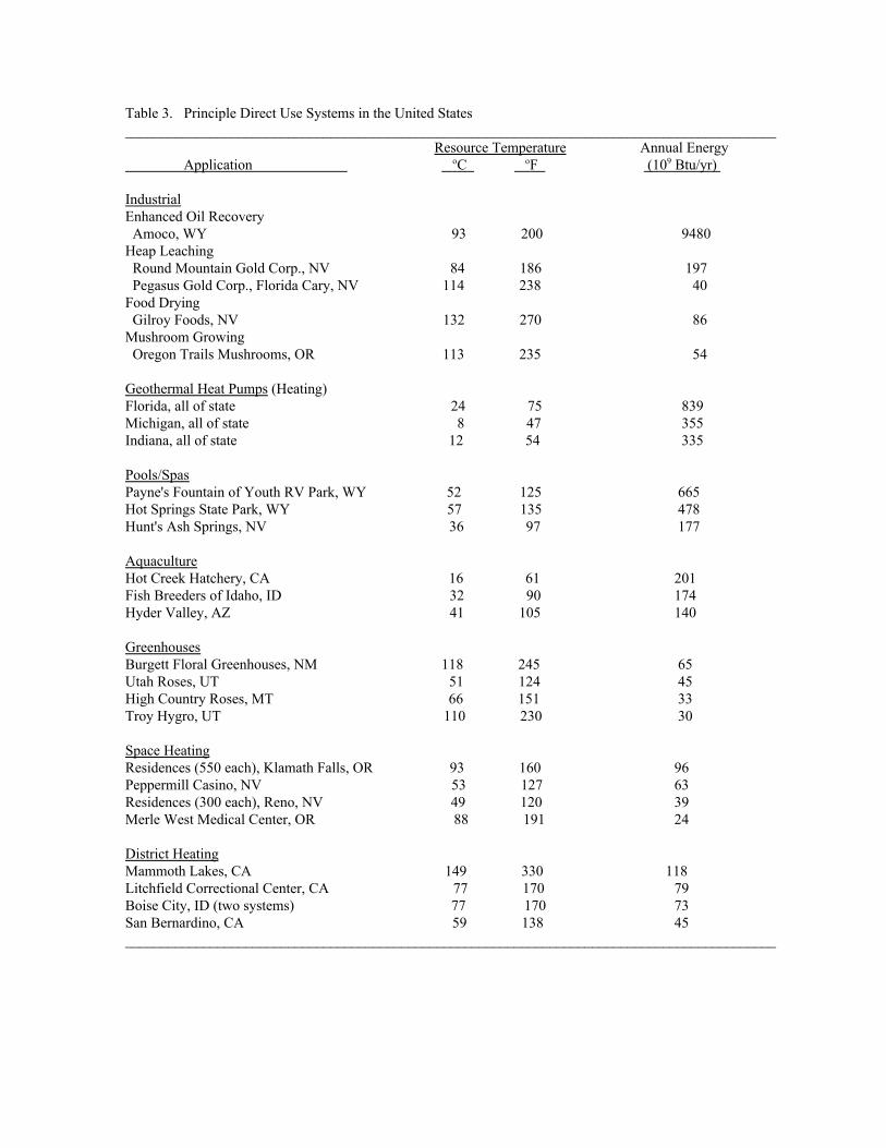
Table 3. Principle Direct Use Systems in the United States____________________________________________________________________________________________ Resource Temperature Annual Energy Application oC oF (109 Btu/yr)
IndustrialEnhanced Oil Recovery Amoco, WY 93 200 9480Heap Leaching Round Mountain Gold Corp., NV 84 186 197 Pegasus Gold Corp., Florida Cary, NV 114 238 40Food Drying Gilroy Foods, NV 132 270 86Mushroom Growing Oregon Trails Mushrooms, OR 113 235 54
Geothermal Heat Pumps (Heating)Florida, all of state 24 75 839Michigan, all of state 8 47 355Indiana, all of state 12 54 335
Pools/SpasPayne's Fountain of Youth RV Park, WY 52 125 665Hot Springs State Park, WY 57 135 478Hunt's Ash Springs, NV 36 97 177
AquacultureHot Creek Hatchery, CA 16 61 201Fish Breeders of Idaho, ID 32 90 174Hyder Valley, AZ 41 105 140
GreenhousesBurgett Floral Greenhouses, NM 118 245 65Utah Roses, UT 51 124 45High Country Roses, MT 66 151 33Troy Hygro, UT 110 230 30
Space HeatingResidences (550 each), Klamath Falls, OR 93 160 96Peppermill Casino, NV 53 127 63Residences (300 each), Reno, NV 49 120 39Merle West Medical Center, OR 88 191 24
District HeatingMammoth Lakes, CA 149 330 118Litchfield Correctional Center, CA 77 170 79Boise City, ID (two systems) 77 170 73San Bernardino, CA 59 138 45____________________________________________________________________________________________
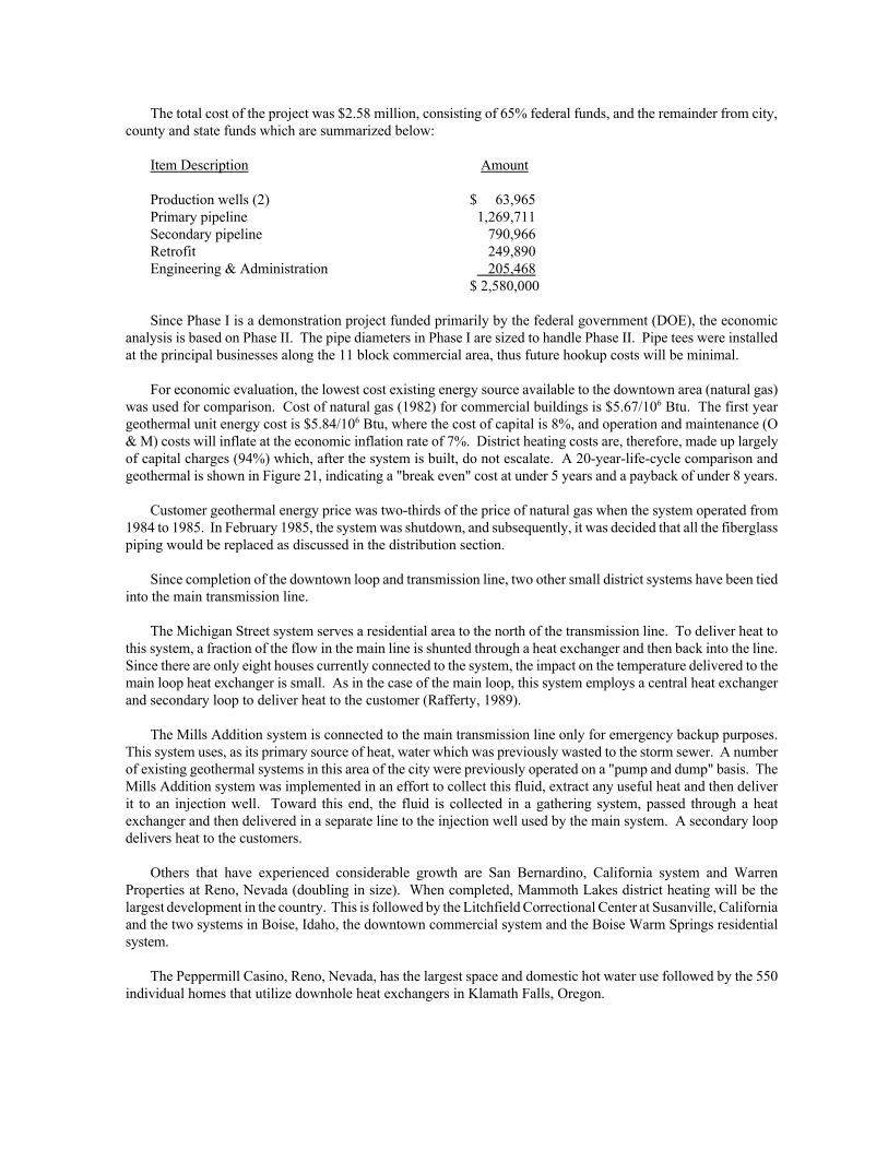
The total cost of the project was $2.58 million, consisting of 65% federal funds, and the remainder from city,county and state funds which are summarized below:
Item Description Amount
Production wells (2) $ 63,965Primary pipeline 1,269,711Secondary pipeline 790,966Retrofit 249,890Engineering & Administration 205,468
$ 2,580,000
Since Phase I is a demonstration project funded primarily by the federal government (DOE), the economicanalysis is based on Phase II. The pipe diameters in Phase I are sized to handle Phase II. Pipe tees were installedat the principal businesses along the 11 block commercial area, thus future hookup costs will be minimal.
For economic evaluation, the lowest cost existing energy source available to the downtown area (natural gas)was used for comparison. Cost of natural gas (1982) for commercial buildings is $5.67/106 Btu. The first yeargeothermal unit energy cost is $5.84/106 Btu, where the cost of capital is 8%, and operation and maintenance (O& M) costs will inflate at the economic inflation rate of 7%. District heating costs are, therefore, made up largelyof capital charges (94%) which, after the system is built, do not escalate. A 20-year-life-cycle comparison andgeothermal is shown in Figure 21, indicating a "break even" cost at under 5 years and a payback of under 8 years.
Customer geothermal energy price was two-thirds of the price of natural gas when the system operated from1984 to 1985. In February 1985, the system was shutdown, and subsequently, it was decided that all the fiberglasspiping would be replaced as discussed in the distribution section.
Since completion of the downtown loop and transmission line, two other small district systems have been tiedinto the main transmission line.
The Michigan Street system serves a residential area to the north of the transmission line. To deliver heat tothis system, a fraction of the flow in the main line is shunted through a heat exchanger and then back into the line.Since there are only eight houses currently connected to the system, the impact on the temperature delivered to themain loop heat exchanger is small. As in the case of the main loop, this system employs a central heat exchangerand secondary loop to deliver heat to the customer (Rafferty, 1989).
The Mills Addition system is connected to the main transmission line only for emergency backup purposes.This system uses, as its primary source of heat, water which was previously wasted to the storm sewer. A numberof existing geothermal systems in this area of the city were previously operated on a "pump and dump" basis. TheMills Addition system was implemented in an effort to collect this fluid, extract any useful heat and then deliverit to an injection well. Toward this end, the fluid is collected in a gathering system, passed through a heatexchanger and then delivered in a separate line to the injection well used by the main system. A secondary loopdelivers heat to the customers.
Others that have experienced considerable growth are San Bernardino, California system and WarrenProperties at Reno, Nevada (doubling in size). When completed, Mammoth Lakes district heating will be thelargest development in the country. This is followed by the Litchfield Correctional Center at Susanville, Californiaand the two systems in Boise, Idaho, the downtown commercial system and the Boise Warm Springs residentialsystem.
The Peppermill Casino, Reno, Nevada, has the largest space and domestic hot water use followed by the 550individual homes that utilize downhole heat exchangers in Klamath Falls, Oregon.

Figure 21. Phase II Unit Energy Cost Comparison (Lienau, 1981).
The potential for geothermal district heating in the United States is very large. An inventory identifies a totalof 1,277 hydrothermal sites within five miles of 373 cities in eight Western states, with a combined population of6,720,000 persons. The combined heat load for all cities (exclusive of industrial loads) is estimated at 1.3 x 10¹⁴
Btu/yr (Allen, 1980). Currently 20 geothermal district heating systems are operating (700 x 109 Btu/yr) and 26planned projects should increase the annual energy use by 1,690 billion Btu per year.
Greenhouses
A number of commercial crops can be raised in greenhouses, making geothermal resources in cold climatesparticularly attractive. Crops include vegetables, flowers (potted and cut), house plants and tree seedlings.
Greenhouse heating can be accomplished by several methods: finned pipe, unit heaters, finned coils, soilheating, plastic tubing, cascading, and a combination of these methods (Rafferty, 1989). The use of geothermalenergy for heating can reduce operating costs and allow operation in colder climates where commercial greenhouseswould not normally be economical.
Economics of a geothermal greenhouse operation depend on many variables, such as the type of crop, climate,resource temperature, type of structure, etc. An example is the raising of roses near Helena, Montana, where usinggeothermal energy in a 75,500 ft2 greenhouse reduces heating costs by 80% and overall costs by 35%.

Greenhouses are one of the fastest growing applications in the direct use industry. A number of the existinggreenhouse systems are expanding. For example, Troy Hygro, Newcastle, Utah, is building an additional 28 acres,which will result in a 100% increase in the total U.S. utilization for greenhouses. Other systems expanding areUtah Roses, Bluffdale, Utah; Flint Greenhouses near Buhl, Idaho (doubling in size) and a new experimental facilityand commercial space with a geothermal delivery system is being constructed by Lake County, California.
Troy-Hygro Greenhouses will be the largest greenhouse energy user when the 28 acre facility is completed.Burgett Floral at Animas, New Mexico, has developed about 13 acres and the state with the largest total use forgreenhouses is Idaho with 14 sites in operation.
Aquaculture
Aquaculture involves the raising of freshwater or marine organisms in a controlled environment to enhanceproduction rates. The principal species that are typically raised are aquatic animals such as catfish, bass, tilapia,sturgeon, shrimp, and tropical fish. The application temperature in fish farming depends on the species involved.Typically, catfish grow in 4 to 6 months at 64 to 75oF, trout in 4 to 6 months at 55 to 64oF and prawns in 6 to 9months at 80 to 86oF. The benefit of a controlled rearing temperature in aquaculture operations can increase growthrates by 50 to 100%, and thus, increase the number of harvests per year. Water quality and disease control are veryimportant in fish farming.
In the U.S. aquaculture projects using geothermal water exist in Arizona, Idaho, Oregon, and California.Aquaculture is one of the fastest growing applications for using low-temperature geothermal energy. Recently, fourlocations in Arizona began raising catfish, tilapia and bass using geothermal fluids with temperatures ranging from80 to 105oF and a large facility is planned for raising sturgeon at Brooks Warms Springs, Montana.
Aquaculture projects at the Hot Creek Hatchery near Mammoth Lakes, California and the Fish Breeders ofIdaho, Buhl, Idaho, are the largest aquaculture use sites.
Resorts and Pools
Geothermal energy used for swimming pools and spas is the earliest use of the resource. Natatoriums and largeresorts developed at hot springs, located in both the eastern and western United States, were popular in the 1800sand were reminiscent of those in Europe. Many of these continue to be used today, and in some cases, elaboratefacilities have been developed. For example, Fairmont Hot Springs Resort, a major new all-year resort near Butte,Montana, is using a 640 ft geothermal well (160oF) for space heating a 140-room hotel, mini-zoo, game room andrestaurant in addition to large indoor and outdoor swimming pools. The resort also boasts a golf course, conventioncenter and time-share condominiums.
The survey identified 114 resorts using geothermal energy, the largest being Paynes Fountain of Youth andHot Springs State Park in Wyoming.
Industrial
Industrial applications mostly need the higher temperatures while space heating and agriculture predominantlyuse low temperatures. Examples of industrial uses include: enhanced oil recovery (200oF), heap leachingoperations to extract precious metals (230oF), dehydration of vegetables (270oF), mushroom growing (235oF), andothers worldwide such as pulp and paper processing (400oF), hay drying (363oF), timber drying (200oF), anddiatomaceous earth drying (360oF).
Drying and dehydration may be the two most important process uses of geothermal energy. A variety ofvegetable and fruit products can be considered for dehydration at geothermal temperatures. Dehydration processesinvolve either continuous belt conveyors or batch dryers, using low temperature air from 100 to 200oF. Blowersand exhaust fans move the air over coils through which the geothermal fluid flows. The heated air then flowsthrough the beds of vegetables or fruit on conveyors, to evaporate the moisture. Geothermal Food Processors near
Fernly, Nevada, dehydrate onions, garlic, celery, and carrots using 270oF geothermal fluid. This saves an estimated86.0 billion Btu/yr which is equivalent to replacing 119 x 106 cubic feet of natural gas corresponding to a savingsof about $350,000 per year. This plant has been operating since 1978.
When oil is produced, only about a third of the oil in the ground can be recovered by simply pumpingproduction wells. Secondary recovery, the injection of water to move oil toward production wells, is often usedto recover up to an additional third of the original oil. In the oil fields of North and South Dakota, Wyoming andMontana, geothermal fluid is produced with the oil from several deep zones. This fluid is often between 140 and212oF as it is produced at the surface, and this heat is extremely useful in the secondary recovery of additional oil.Efficient secondary oil recovery is a function of the temperature and chemical compatibility of the injected watercompared to the oil formation. To calculate the benefit from the use of the geothermal fluid, a comparison is madebetween the geothermal water and the energy needed to heat surface water to the same temperature. The estimatedbenefit for secondary oil recovery in the four states is 8,156.2 x 109 Btu/yr; however, fluctuating oil prices mayimpact the degree to which it is utilized.
Large volumes of geothermal fluid are separated from oil production or are produced from other zones for usein secondary oil recovery. The injected water use in the four states mentioned above comes primarily from theDakota Sandstone and the deeper Madison Limestone. Dakota aquifer water ranges between 140 and 170oF andMadison aquifer water ranges between 160 and 212oF.
New developments in 1988 are the use of geothermal fluids for enhanced heap leaching of precious metals inNevada by heating the cyanide circuit. This represents an additional 300 billion Btu/yr of energy use or a 3%growth.
FEASIBILITY
The decision to invest in a geothermal project depends primarily upon the annual savings over an alternativefuel system, taking into account the project life, system maintenance, cost of money and fuel price projections.Direct use projects require a relatively large capital investment at the beginning, with small annual operating coststhereafter. Production wells, pipelines, heat exchangers and injection wells may cost much more than the initialinvestment of a fossil fuel system. However, the fossil fuel system must continue to pay for the oil, gas or coal ata high rate. The annual operation and maintenance costs for the two systems are similar. The two systems, onewith a high initial cost, and the other with high annual costs, must be compared when evaluating the feasibility ofdirect use projects.
The economics of geothermal direct use projects are affected by several factors, including the location of userand resource, efficiency of heat extraction and annual load factor, cost of financing, amortization period andinflation rates. These factors can be grouped into three major considerations.
1. Locations and site specificity. Direct use projects are site specific because the resource location andcharacteristics must be compatible with the use. The relocation of new potential users and/or the retrofittingof existing potential users are important alternatives. Pipeline lengths for transmission and distribution are asignificant cost of any geothermal project. The location of users near the resource can help reduce the cost oftransmission lines. The depth of drilling determines the cost of production and injection wells. The trade-offbetween shallow and cooler wells using heat pumps, and deeper and hotter wells used directly, is also aconsideration. Water quality affects system design and maintenance costs. In low-to-moderate temperaturereservoirs, the water level determines the setting of downhole pumps and the associated costs of pumping. Therate of pressure and temperature depletion of these and higher temperature reservoirs used for direct uses, aresite specific and prescribe how many make-up wells need to be drilled.

2. System efficiency and load factor. In a geothermal direct heat system, increasing the amount of heat extractedfrom the fluid will decrease the cost of energy. A more expensive heat extraction system is required ingeothermal applications then commonly used in systems burning fossil fuels; but, this is offset by the reductionin the number of production wells required. Cascaded use in one way of increasing the amount of heatextracted from geothermal fluids. Users with a high thermal load density will require smaller distributionsystems which will reduce costs. The load factor of direct use systems is the ratio of the average annual loadto the peak load. As this factor increases, the economic feasibility increases. The load factor of district heatingsystems depends on the local climate mainly. Hot water storage can improve the load factor of district heatingsystems. The use of fossil fuel or electric heating peaking systems can help reduce the peak geothermal load,and thus, reduce the number of wells required.
3. Financing and fuel costs. As the rate of return or the cost of borrowed money increases, the economic viabilityof a project decreases. It is important that the economic life of a project be kept relatively short, 20 years orless, although most projects last much longer. Also, inflation rates for fossil fuels should be kept conservative(low) when comparing with a geothermal alternative. By using long life and high inflation rates, feasibilitystudies make geothermal energy look extremely attractive when in fact the project may well operate in the redfor its entire life. By holding the economic life and inflation rates low, projects that have good economicfeasibility will be even more attractive if the actual life proves to be longer or the inflation rate is higher.
The important components of a typical geothermal feasibility study are: (1) to prove the resource, (2) to ensurethat the end use is compatible with the temperature and flow rate of the resource, and (3) to determine if the projectis economically feasible. Life cycle cost analysis is the method generally used to determine economic feasibility.It should include capital investment, annual maintenance and operating costs, financing cost and taxes andinsurance.
CONCLUSIONS
The contained heat energy beneath the United States could, in theory, provide most of the future lowtemperature energy needs of this Nation. The actual contribution will be determined by the effort--time, people,and funding--devoted to a broad research, development, and demonstration program with participation by federal,state, and local governments in cooperation with industry, universities, laboratories and the American people.
The United States direct use industry is and will continue to experience a significant growth rate. The largestgrowth should continue to occur in the use of geothermal heat pumps, and aquaculture, greenhousing and districtheating will add to the expansion of the industry.
REFERENCES
Culver, G. G. and K. Rafferty, 1989. "Well Pumps," Geothermal Direct Use Engineering and Design Guidebook,Oregon Institute of Technology, Geo-Heat Center, Klamath Falls, OR, pp. 167-200.
Culver, G. G. and G. M. Reistad, 1978. Evaluation and Design of Downhole Heat Exchangers for DirectApplication, report to USDOE, Geo-Heat Center, Klamath Falls, OR.
Lienau, P. J., 1981. "Design of the Klamath Falls Geothermal District Heating Network," ASHRAE Transactions,Vol. 87, p. 2, Atlanta, GA.
Lienau, P.J., J. W. Lund, and G. G. Culver, 1988. "Geothermal Direct Use Developments in the United States,"report to USDOE, Oregon Institute of Technology, Geo-Heat Center, Klamath Falls, OR.
Lund, J. W., 1978. Geothermal Energy Utilization for the Homeowner, prepared for Oregon Department ofEnergy, Oregon Institute of Technology, Geo-Heat Center, Klamath Falls, OR.

Muffler, L. P. J., 1979. "Assessment of Geothermal Resources of the United States - 1978," Geological SurveyCircular 790, Arlington, VA.
Oklahoma State University, Division of Engineering Technology, 1988. Closed - Loop/Ground - Source Heat PumpSystems - Installation Guide, International Ground Source Heat Pump Association, Stillwater, OK.
Rafferty, K., 1989. A Materials and Equipment Review of Selected U.S. Geothermal District Heating Systems,report to USDOE, Geo-Heat Center, Klamath Falls, OR.
Rafferty, K., 1989. "Absorption Refrigeration" Geothermal Direct Use Engineering and Design Guidebook, OregonInstitute of Technology, Geo-Heat Center, Klamath Falls, OR, pp. 261-270.
Rafferty, K. and P. J. Lienau, 1988. OIT Geothermal System, Oregon Institute of Technology, Geo-Heat Center,Klamath Falls, OR.
Reed, M. J., (editor), 1983. "Assessment of Low-Temperature Geothermal Resources of the United States - 1982,"Geological Survey Circular 892, Alexandria, VA.
Reistad, G. M., 1975. "Potential for Non-Electrical Applications of Geothermal Energy and Their Place in the National Economy," Proceedings Second U.N. Symposium, Development Use of Geothermal Resources, San
Francisco, CA, pp. 2117-2126.
Ryan, G. P., 1981. "Equipment Used in Direct Heat Projects," Transaction, Geothermal Resources Council, Vol. 5, pp. 483-485.
Tester, J., 1982. "Energy Conversion and Economic Issues for Geothermal Energy," Handbook of Geothermal Energy, Gulf Publishing Company, Houston, TX, pp. 471-588.
Witcher, J. C., 1980. "Geothermal Space Heating/Cooling," Geo-Heat Center Bulletin, Vol. 5, pp. 18-20.

Figure 5. Typical lineshaft turbine pump with an enclosed oil-lubricated shaft (Culver and Rafferty, 1989).