direct drive robot user guide - chemical analysis, life … · 2016-08-30 · preface about this...
TRANSCRIPT

BenchBot Robot
User GuideOriginal instructions
Agilent Technologies

Notices© Agilent Technologies, Inc. 2014
No part of this manual may be reproduced in any form or by any means (including electronic storage and retrieval or transla-tion into a foreign language) without prior agreement and written consent from Agi-lent Technologies, Inc. as governed by United States and international copyright laws.
User Guide Part Number
G5486-90003
Edition
Revision B, March 2014
Contact Information
Agilent Technologies Inc. Automation Solutions 5301 Stevens Creek Blvd. Santa Clara, CA 95051 USA
Technical Support: 1.800.979.4811 or +1.408.345.8011 [email protected]
Customer Service: 1.866.428.9811 or +1.408.345.8356 [email protected]
European Service: +44 (0)1763850230 [email protected]
Documentation feedback: [email protected]
Web: www.agilent.com/lifesciences/ automation
Acknowledgements
Adobe® and Acrobat® are trademarks of Adobe Systems Incorporated.
Microsoft® and Windows® are either registered trademarks or trademarks of the Microsoft Corporation in the United States and other countries.
Warranty
The material contained in this docu-ment is provided “as is,” and is sub-ject to being changed, without notice, in future editions. Further, to the max-imum extent permitted by applicable law, Agilent disclaims all warranties, either express or implied, with regard to this manual and any information contained herein, including but not limited to the implied warranties of merchantability and fitness for a par-ticular purpose. Agilent shall not be liable for errors or for incidental or consequential damages in connection with the furnishing, use, or perfor-mance of this document or of any information contained herein. Should Agilent and the user have a separate written agreement with warranty terms covering the material in this document that conflict with these terms, the warranty terms in the sep-arate agreement shall control.
Technology Licenses
The hardware and/or software described in this document are furnished under a license and may be used or copied only in accordance with the terms of such license.
Restricted Rights Legend
If software is for use in the performance of a U.S. Government prime contract or sub-contract, Software is delivered and licensed as “Commercial computer soft-ware” as defined in DFAR 252.227-7014 (June 1995), or as a “commercial item” as defined in FAR 2.101(a) or as “Restricted computer software” as defined in FAR 52.227-19 (June 1987) or any equivalent agency regulation or contract clause. Use, duplication or disclosure of Software is subject to Agilent Technologies’ standard commercial license terms, and non-DOD Departments and Agencies of the U.S. Gov-ernment will receive no greater than Restricted Rights as defined in FAR 52.227-19(c)(1-2) (June 1987). U.S. Government users will receive no greater than Limited Rights as defined in FAR 52.227-14
(June1987) or DFAR 252.227-7015 (b)(2) (November 1995), as applicable in any technical data.
Safety Notices
A WARNING notice denotes a hazard. It calls attention to an operating procedure, practice, or the like that, if not correctly performed or adhered to, could result in personal injury or death. Do not proceed beyond a WARNING notice until the indicated conditions are fully understood and met.
A CAUTION notice denotes a hazard. It calls attention to an operating procedure, practice, or the like that, if not correctly performed or adhered to, could result in damage to the product or loss of important data. Do not proceed beyond a CAUTION notice until the indicated conditions are fully understood and met.
Contents
Contents
Preface . . . . . . . . . . . . . . . . . . . . . . . . . . . . . . . . . . . . . . . . . . . . . . . . . . . . . . . . . . . . . . . . . . . . . . . . . . . . . . . . . . . . . . viiAbout this guide . . . . . . . . . . . . . . . . . . . . . . . . . . . . . . . . . . . . . . . . . . . . . . . . . . . . . . . . . . . . . . . . . . . . . . . . . . . . . . viiiAccessing Automation Solutions user guides . . . . . . . . . . . . . . . . . . . . . . . . . . . . . . . . . . . . . . . . . . . . . . . . . . . . . . . x
1. Introduction to the BenchBot Robot . . . . . . . . . . . . . . . . . . . . . . . . . . . . . . . . . . . . . . . . . . . . . . . . . . . . . . . . 1About the BenchBot Robot . . . . . . . . . . . . . . . . . . . . . . . . . . . . . . . . . . . . . . . . . . . . . . . . . . . . . . . . . . . . . . . . . . . . . . 2Hardware components. . . . . . . . . . . . . . . . . . . . . . . . . . . . . . . . . . . . . . . . . . . . . . . . . . . . . . . . . . . . . . . . . . . . . . . . . . . 4Device integration options . . . . . . . . . . . . . . . . . . . . . . . . . . . . . . . . . . . . . . . . . . . . . . . . . . . . . . . . . . . . . . . . . . . . . . 11Software overview . . . . . . . . . . . . . . . . . . . . . . . . . . . . . . . . . . . . . . . . . . . . . . . . . . . . . . . . . . . . . . . . . . . . . . . . . . . . . 13Quick start . . . . . . . . . . . . . . . . . . . . . . . . . . . . . . . . . . . . . . . . . . . . . . . . . . . . . . . . . . . . . . . . . . . . . . . . . . . . . . . . . . . . 16
2. Setting up the BenchBot Robot . . . . . . . . . . . . . . . . . . . . . . . . . . . . . . . . . . . . . . . . . . . . . . . . . . . . . . . . . . . . 19Setup workflow . . . . . . . . . . . . . . . . . . . . . . . . . . . . . . . . . . . . . . . . . . . . . . . . . . . . . . . . . . . . . . . . . . . . . . . . . . . . . . . . 20Turning on and turning off the robot . . . . . . . . . . . . . . . . . . . . . . . . . . . . . . . . . . . . . . . . . . . . . . . . . . . . . . . . . . . . . . 21Creating a device file . . . . . . . . . . . . . . . . . . . . . . . . . . . . . . . . . . . . . . . . . . . . . . . . . . . . . . . . . . . . . . . . . . . . . . . . . . . 23Adding and deleting BenchBot Robots in the device file . . . . . . . . . . . . . . . . . . . . . . . . . . . . . . . . . . . . . . . . . . . . 25Creating BenchBot Robot profiles . . . . . . . . . . . . . . . . . . . . . . . . . . . . . . . . . . . . . . . . . . . . . . . . . . . . . . . . . . . . . . . 29Setting up robot communication . . . . . . . . . . . . . . . . . . . . . . . . . . . . . . . . . . . . . . . . . . . . . . . . . . . . . . . . . . . . . . . . . 31Selecting a teachpoint file. . . . . . . . . . . . . . . . . . . . . . . . . . . . . . . . . . . . . . . . . . . . . . . . . . . . . . . . . . . . . . . . . . . . . . . 34Saving the profile . . . . . . . . . . . . . . . . . . . . . . . . . . . . . . . . . . . . . . . . . . . . . . . . . . . . . . . . . . . . . . . . . . . . . . . . . . . . . . 36Initializing the profile . . . . . . . . . . . . . . . . . . . . . . . . . . . . . . . . . . . . . . . . . . . . . . . . . . . . . . . . . . . . . . . . . . . . . . . . . . . 37Editing and managing profiles . . . . . . . . . . . . . . . . . . . . . . . . . . . . . . . . . . . . . . . . . . . . . . . . . . . . . . . . . . . . . . . . . . . 39
3. Setting teachpoints . . . . . . . . . . . . . . . . . . . . . . . . . . . . . . . . . . . . . . . . . . . . . . . . . . . . . . . . . . . . . . . . . . . . . . . 41Teachpoint setting workflow . . . . . . . . . . . . . . . . . . . . . . . . . . . . . . . . . . . . . . . . . . . . . . . . . . . . . . . . . . . . . . . . . . . . 42Planning BenchBot Robot teachpoints . . . . . . . . . . . . . . . . . . . . . . . . . . . . . . . . . . . . . . . . . . . . . . . . . . . . . . . . . . . . 44Setting new teachpoints . . . . . . . . . . . . . . . . . . . . . . . . . . . . . . . . . . . . . . . . . . . . . . . . . . . . . . . . . . . . . . . . . . . . . . . . 51Specifying the A1-well orientation. . . . . . . . . . . . . . . . . . . . . . . . . . . . . . . . . . . . . . . . . . . . . . . . . . . . . . . . . . . . . . . . 57Selecting the teachpoint type . . . . . . . . . . . . . . . . . . . . . . . . . . . . . . . . . . . . . . . . . . . . . . . . . . . . . . . . . . . . . . . . . . . . 59Setting the Approach Height and Approach Distance parameters. . . . . . . . . . . . . . . . . . . . . . . . . . . . . . . . . . . . . 61Setting the Min and Max Gripper Offset parameters . . . . . . . . . . . . . . . . . . . . . . . . . . . . . . . . . . . . . . . . . . . . . . . . 65Setting the X, Y, Z, and Yaw parameters . . . . . . . . . . . . . . . . . . . . . . . . . . . . . . . . . . . . . . . . . . . . . . . . . . . . . . . . . . . 67Adding multiple orientations to a teachpoint. . . . . . . . . . . . . . . . . . . . . . . . . . . . . . . . . . . . . . . . . . . . . . . . . . . . . . . 68Saving the teachpoints . . . . . . . . . . . . . . . . . . . . . . . . . . . . . . . . . . . . . . . . . . . . . . . . . . . . . . . . . . . . . . . . . . . . . . . . . 69Setting teachpoints using a labware . . . . . . . . . . . . . . . . . . . . . . . . . . . . . . . . . . . . . . . . . . . . . . . . . . . . . . . . . . . . . . 70Verifying teachpoints . . . . . . . . . . . . . . . . . . . . . . . . . . . . . . . . . . . . . . . . . . . . . . . . . . . . . . . . . . . . . . . . . . . . . . . . . . . 71Editing existing teachpoints . . . . . . . . . . . . . . . . . . . . . . . . . . . . . . . . . . . . . . . . . . . . . . . . . . . . . . . . . . . . . . . . . . . . . 81Managing teachpoints . . . . . . . . . . . . . . . . . . . . . . . . . . . . . . . . . . . . . . . . . . . . . . . . . . . . . . . . . . . . . . . . . . . . . . . . . . 86Cycling teachpoints . . . . . . . . . . . . . . . . . . . . . . . . . . . . . . . . . . . . . . . . . . . . . . . . . . . . . . . . . . . . . . . . . . . . . . . . . . . . 87
iiiBenchBot User Guide

Contents
4. Preparing for a protocol run. . . . . . . . . . . . . . . . . . . . . . . . . . . . . . . . . . . . . . . . . . . . . . . . . . . . . . . . . . . . . . . 91Workflow for preparing a protocol run . . . . . . . . . . . . . . . . . . . . . . . . . . . . . . . . . . . . . . . . . . . . . . . . . . . . . . . . . . . . 92Planning for the protocol run . . . . . . . . . . . . . . . . . . . . . . . . . . . . . . . . . . . . . . . . . . . . . . . . . . . . . . . . . . . . . . . . . . . . 93Performing dry runs . . . . . . . . . . . . . . . . . . . . . . . . . . . . . . . . . . . . . . . . . . . . . . . . . . . . . . . . . . . . . . . . . . . . . . . . . . . . 94Stopping the robot in an emergency . . . . . . . . . . . . . . . . . . . . . . . . . . . . . . . . . . . . . . . . . . . . . . . . . . . . . . . . . . . . . . 95
5. Using BenchBot Diagnostics . . . . . . . . . . . . . . . . . . . . . . . . . . . . . . . . . . . . . . . . . . . . . . . . . . . . . . . . . . . . . . 97About BenchBot Robot Diagnostics . . . . . . . . . . . . . . . . . . . . . . . . . . . . . . . . . . . . . . . . . . . . . . . . . . . . . . . . . . . . . . 98Checking the robot status and log . . . . . . . . . . . . . . . . . . . . . . . . . . . . . . . . . . . . . . . . . . . . . . . . . . . . . . . . . . . . . . . 100Homing the robot and grippers. . . . . . . . . . . . . . . . . . . . . . . . . . . . . . . . . . . . . . . . . . . . . . . . . . . . . . . . . . . . . . . . . . 103Retracting the robot into the robot zone. . . . . . . . . . . . . . . . . . . . . . . . . . . . . . . . . . . . . . . . . . . . . . . . . . . . . . . . . . 106Jogging the robot . . . . . . . . . . . . . . . . . . . . . . . . . . . . . . . . . . . . . . . . . . . . . . . . . . . . . . . . . . . . . . . . . . . . . . . . . . . . 109Disabling and enabling the robot joint motors. . . . . . . . . . . . . . . . . . . . . . . . . . . . . . . . . . . . . . . . . . . . . . . . . . . . . 113Stopping the robot motors . . . . . . . . . . . . . . . . . . . . . . . . . . . . . . . . . . . . . . . . . . . . . . . . . . . . . . . . . . . . . . . . . . . . . 115Changing the robot speed . . . . . . . . . . . . . . . . . . . . . . . . . . . . . . . . . . . . . . . . . . . . . . . . . . . . . . . . . . . . . . . . . . . . . . 117Changing the robot speed definitions . . . . . . . . . . . . . . . . . . . . . . . . . . . . . . . . . . . . . . . . . . . . . . . . . . . . . . . . . . . 119Opening and closing the robot grippers . . . . . . . . . . . . . . . . . . . . . . . . . . . . . . . . . . . . . . . . . . . . . . . . . . . . . . . . . . 122Changing the gripper settings . . . . . . . . . . . . . . . . . . . . . . . . . . . . . . . . . . . . . . . . . . . . . . . . . . . . . . . . . . . . . . . . . . 125Updating the firmware . . . . . . . . . . . . . . . . . . . . . . . . . . . . . . . . . . . . . . . . . . . . . . . . . . . . . . . . . . . . . . . . . . . . . . . . 127Backing up the robot firmware. . . . . . . . . . . . . . . . . . . . . . . . . . . . . . . . . . . . . . . . . . . . . . . . . . . . . . . . . . . . . . . . . . 129Installing new or restoring existing firmware . . . . . . . . . . . . . . . . . . . . . . . . . . . . . . . . . . . . . . . . . . . . . . . . . . . . . 131
6. Maintaining the robot . . . . . . . . . . . . . . . . . . . . . . . . . . . . . . . . . . . . . . . . . . . . . . . . . . . . . . . . . . . . . . . . . . . 133Routine maintenance. . . . . . . . . . . . . . . . . . . . . . . . . . . . . . . . . . . . . . . . . . . . . . . . . . . . . . . . . . . . . . . . . . . . . . . . . . 134Cleaning the robot gripper pads . . . . . . . . . . . . . . . . . . . . . . . . . . . . . . . . . . . . . . . . . . . . . . . . . . . . . . . . . . . . . . . . . 135Replacing robot gripper pads . . . . . . . . . . . . . . . . . . . . . . . . . . . . . . . . . . . . . . . . . . . . . . . . . . . . . . . . . . . . . . . . . . . 137Replacing robot grippers . . . . . . . . . . . . . . . . . . . . . . . . . . . . . . . . . . . . . . . . . . . . . . . . . . . . . . . . . . . . . . . . . . . . . . . 140Replacing fuses. . . . . . . . . . . . . . . . . . . . . . . . . . . . . . . . . . . . . . . . . . . . . . . . . . . . . . . . . . . . . . . . . . . . . . . . . . . . . . . 143
7. Troubleshooting robot problems . . . . . . . . . . . . . . . . . . . . . . . . . . . . . . . . . . . . . . . . . . . . . . . . . . . . . . . . . 147Recovering from an emergency stop. . . . . . . . . . . . . . . . . . . . . . . . . . . . . . . . . . . . . . . . . . . . . . . . . . . . . . . . . . . . . 148Resolving robot initialization errors. . . . . . . . . . . . . . . . . . . . . . . . . . . . . . . . . . . . . . . . . . . . . . . . . . . . . . . . . . . . . . 150Recovering from servo errors . . . . . . . . . . . . . . . . . . . . . . . . . . . . . . . . . . . . . . . . . . . . . . . . . . . . . . . . . . . . . . . . . . . 151Troubleshooting hardware problems . . . . . . . . . . . . . . . . . . . . . . . . . . . . . . . . . . . . . . . . . . . . . . . . . . . . . . . . . . . . 153Troubleshooting error messages . . . . . . . . . . . . . . . . . . . . . . . . . . . . . . . . . . . . . . . . . . . . . . . . . . . . . . . . . . . . . . . . 157Reporting problems . . . . . . . . . . . . . . . . . . . . . . . . . . . . . . . . . . . . . . . . . . . . . . . . . . . . . . . . . . . . . . . . . . . . . . . . . . . 165
A. Quick reference . . . . . . . . . . . . . . . . . . . . . . . . . . . . . . . . . . . . . . . . . . . . . . . . . . . . . . . . . . . . . . . . . . . . . . . . . 167Robot status area . . . . . . . . . . . . . . . . . . . . . . . . . . . . . . . . . . . . . . . . . . . . . . . . . . . . . . . . . . . . . . . . . . . . . . . . . . . . . 168Log area . . . . . . . . . . . . . . . . . . . . . . . . . . . . . . . . . . . . . . . . . . . . . . . . . . . . . . . . . . . . . . . . . . . . . . . . . . . . . . . . . . . . . 170General commands . . . . . . . . . . . . . . . . . . . . . . . . . . . . . . . . . . . . . . . . . . . . . . . . . . . . . . . . . . . . . . . . . . . . . . . . . . . 171Jog/Move tab . . . . . . . . . . . . . . . . . . . . . . . . . . . . . . . . . . . . . . . . . . . . . . . . . . . . . . . . . . . . . . . . . . . . . . . . . . . . . . . . 172Teachpoints tab . . . . . . . . . . . . . . . . . . . . . . . . . . . . . . . . . . . . . . . . . . . . . . . . . . . . . . . . . . . . . . . . . . . . . . . . . . . . . . 177Cycler tab . . . . . . . . . . . . . . . . . . . . . . . . . . . . . . . . . . . . . . . . . . . . . . . . . . . . . . . . . . . . . . . . . . . . . . . . . . . . . . . . . . . . 180Setup tab . . . . . . . . . . . . . . . . . . . . . . . . . . . . . . . . . . . . . . . . . . . . . . . . . . . . . . . . . . . . . . . . . . . . . . . . . . . . . . . . . . . . 181Profiles tab. . . . . . . . . . . . . . . . . . . . . . . . . . . . . . . . . . . . . . . . . . . . . . . . . . . . . . . . . . . . . . . . . . . . . . . . . . . . . . . . . . . 184
iv BenchBot User Guide

Contents
B. Orderable parts . . . . . . . . . . . . . . . . . . . . . . . . . . . . . . . . . . . . . . . . . . . . . . . . . . . . . . . . . . . . . . . . . . . . . . . . . . 187Ordering information . . . . . . . . . . . . . . . . . . . . . . . . . . . . . . . . . . . . . . . . . . . . . . . . . . . . . . . . . . . . . . . . . . . . . . . . . . 188Parts list . . . . . . . . . . . . . . . . . . . . . . . . . . . . . . . . . . . . . . . . . . . . . . . . . . . . . . . . . . . . . . . . . . . . . . . . . . . . . . . . . . . . . 189
Index . . . . . . . . . . . . . . . . . . . . . . . . . . . . . . . . . . . . . . . . . . . . . . . . . . . . . . . . . . . . . . . . . . . . . . . . . . . . . . . . . . . . . . . 191
vBenchBot User Guide

Contents
vi BenchBot User Guide

BenchBot RobotUser Guide
PrefaceThis preface contains the following topics:
• “About this guide” on page viii
• “Accessing Automation Solutions user guides” on page x
vii
Agilent Technologies

PrefaceAbout this guide
About this guide
Who should read this guide
This user guide is for people with the following job roles:
Installers, integrators, lab managers, and administrators are users who must have technical expertise. In addition, lab managers and administrators are individuals or groups responsible for the use and maintenance of the BenchBot Robot and for ensuring that operators are adequately trained.
What this guide covers
This guide describes the Agilent BenchBot Robot and the operation of the hardware components using Agilent BenchBot Robot Diagnostics.
This guide does not provide instructions for the following:
• Installation instructions
• VWorks software or third- party automation software
• Agilent Technologies devices, such as the Bravo Automated Liquid Handling Platform, PlateLoc Thermal Microplate Sealer, Microplate Seal Piercer, Microplate Labeler, Vertical Pipetting Station, Microplate Centrifuge, and Labware Stacker.
• Third- party devices
See “Related guides” on page ix.
Software version
This guide documents the following:
• BenchBot Diagnostics version 1.0.x or later
• BenchBot firmware version 1.0.x or later
Job role Responsibilities
Installer Unpacks, installs, and tests the BenchBot Robot before it is used.
Integrator Configures hardware and writes software.
Lab manager, administrator, or technician
• Manages the automation system that contains the BenchBot Robot
• Develops the applications that are run on the system
• Develops training materials and standard operating procedures for operators
Operator Performs the daily production work on the BenchBot Robot and solves routine problems.
viii BenchBot Robot User Guide
PrefaceAbout this guide
Related guides
This user guide should be used in conjunction with the following documents:
• BenchBot Robot Unpacking Guide. Explains how to unpack and pack the robot.
• BenchBot Robot Safety and Installation Guide. Provides the Agilent BenchBot Robot specifications, site requirements, and installation instructions. The guide also describes the potential safety hazards and how to avoid them.
• VWorks Automation Control Setup Guide. Explains how to install the VWorks software, define labware, track labware, and manage users.
• VWorks Automation Control User Guide. Explains how to add devices, create protocols, set task parameters, and run protocols.
• VWorks Software Quick Start. Provides an overview of how to use the VWorks Automation Control software.
• Automation Solutions device user guides. Explains how to set up and use the Automation Solutions devices.
• Third- party device user documents. Explains how to set up and use the third- party devices.
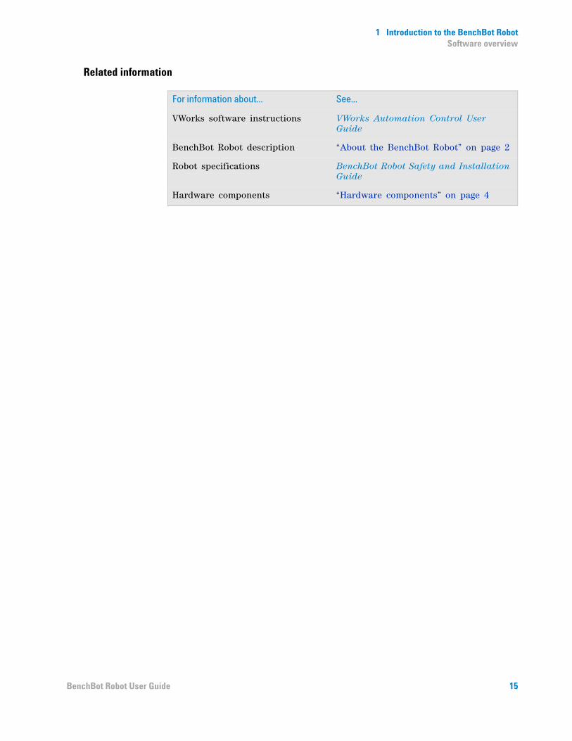
Related information
For information about... See...
Accessing related user guides “Accessing Automation Solutions user guides” on page x
Reporting problems “Reporting problems” on page 165
ixBenchBot Robot User Guide

PrefaceAccessing Automation Solutions user guides
Accessing Automation Solutions user guides
About this topic
This topic describes the different formats of Automation Solutions user information and explains how to access the user information.
Where to find user information
The Automation Solutions user information is available in the following locations:
• Knowledge base. The help system that contains information about all of the Automation Solutions products is available from the Help menu within the VWorks software.
• PDF files. The PDF files of the user guides are installed with the VWorks software and are on the software CD that is supplied with the product. A PDF viewer is required to open a user guide in PDF format. You can download a free PDF viewer from the internet. For information about using PDF documents, see the user documentation for the PDF viewer.
• Agilent Technologies website. You can search the online knowledge base or download the latest version of any PDF file from the Agilent Technologies website at www.agilent.com/lifesciences/automation.
Accessing safety information
Safety information for the Agilent Technologies devices appears in the corresponding device safety guide or user guide.
You can also search the knowledge base or the PDF files for safety information.
Using the knowledge base
Knowledge base topics are displayed using web browser software such as Microsoft Internet Explorer and Mozilla Firefox.
Note: If you want to use Internet Explorer to display the topics, you might have to allow local files to run active content (scripts and ActiveX controls). To do this, in Internet Explorer, open the Internet Options dialog box. Click the Advanced tab, locate the Security section, and select Allow active content to run in files on my computer.
To open the knowledge base, do one of the following:
• From within VWorks software, select Help > Knowledge Base or press F1.
• From the Windows desktop, select Start > All Programs > Agilent Technologies > VWorks > User Guides > Knowledge Base.
x BenchBot Robot User Guide
PrefaceAccessing Automation Solutions user guides
Opening the help topic for an area in the VWorks window
To access the context-sensitive help feature:
1 In the main window of the VWorks software, click the help button .
The pointer changes to . Notice that the different icons or areas are highlighted as you move the pointer over them.
2 Click an icon or area of interest. The relevant topic or document opens.
xiBenchBot Robot User Guide
PrefaceAccessing Automation Solutions user guides
Features in the Knowledge Base window
Item Feature
1 Navigation area. Consists of four tabs:
• Contents. Lists all the books and the table of contents of the books.
• Index. Displays the index entries of all of the books.
• Search. Allows you to search the Knowledge Base (all products) using keywords. You can narrow the search by product.
• Favorites. Contains bookmarks you have created.
2 Navigation buttons. Enable you to navigate through the next or previous topics listed in the Contents tab.
3 Content area. Displays the selected online help topic.
4 Toolbar buttons. Enable you to print the topic or send documentation feedback by email.
xii BenchBot Robot User Guide

PrefaceAccessing Automation Solutions user guides
Related information
For information about... See...
Who should read this guide “About this guide” on page viii
What this guide covers “About this guide” on page viii
Reporting problems “Reporting problems” on page 165
xiiiBenchBot Robot User Guide

PrefaceAccessing Automation Solutions user guides
xiv BenchBot Robot User Guide

BenchBot RobotUser Guide
1 Introduction to the BenchBot Robot
This chapter contains the following topics:
• “About the BenchBot Robot” on page 2
• “Hardware components” on page 4
• “Device integration options” on page 11
• “Software overview” on page 13
• “Quick start” on page 16
1
1 Introduction to the BenchBot RobotAbout the BenchBot Robot
About the BenchBot Robot
Description
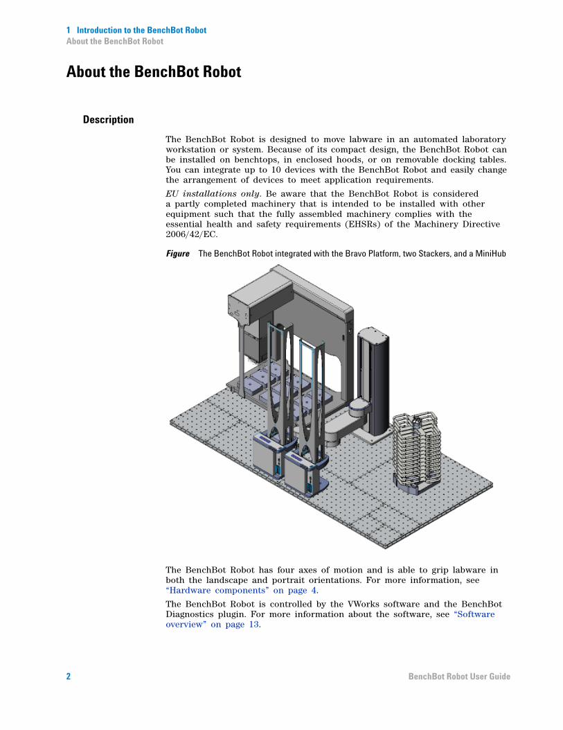
The BenchBot Robot is designed to move labware in an automated laboratory workstation or system. Because of its compact design, the BenchBot Robot can be installed on benchtops, in enclosed hoods, or on removable docking tables. You can integrate up to 10 devices with the BenchBot Robot and easily change the arrangement of devices to meet application requirements.
EU installations only. Be aware that the BenchBot Robot is considered a partly completed machinery that is intended to be installed with other equipment such that the fully assembled machinery complies with the essential health and safety requirements (EHSRs) of the Machinery Directive 2006/42/EC.
Figure The BenchBot Robot integrated with the Bravo Platform, two Stackers, and a MiniHub
The BenchBot Robot has four axes of motion and is able to grip labware in both the landscape and portrait orientations. For more information, see “Hardware components” on page 4.
The BenchBot Robot is controlled by the VWorks software and the BenchBot Diagnostics plugin. For more information about the software, see “Software overview” on page 13.
2 BenchBot Robot User Guide
1 Introduction to the BenchBot RobotAbout the BenchBot Robot
Configurations
The BenchBot Robot is available in the following configurations:
If you have the standalone/component configuration and would like to construct a workstation, you can order the BenchBot integration plates and safety equipment. Contact Automation Solutions Customer Service for details.
Before you operate the system
Related information
Product name Product components
G5486A BenchBot Robot (workstation configuration)
BenchBot Robot (G5486- 00001)
Computer
Emergency- stop pendant
Regrip station
VWorks software
Integration plates
Safety equipment
G5487A BenchBot Robot (standalone/component configuration)
BenchBot Robot (G5486- 00001)
Computer
Emergency- stop pendant
Regrip station
VWorks software
WARNING For safe operation, it is imperative that you follow the precautions in the BenchBot Robot Safety and Installation Guide.
For information about... See...
BenchBot Robot features “Hardware components” on page 4
BenchBot Robot specifications BenchBot Robot Safety and Installation Guide
Software that controls the BenchBot Robot
“Software overview” on page 13
Safety information BenchBot Robot Safety and Installation Guide
Installation instructions BenchBot Robot Safety and Installation Guide
Ordering integration plates and light curtain
“Orderable parts” on page 187
3BenchBot Robot User Guide
1 Introduction to the BenchBot RobotHardware components
Hardware components
About this topic
This topic describes the following BenchBot Robot hardware features:
• “Robot components” on page 4
• “Power and communication” on page 7
• “Emergency- stop pendant” on page 8
• “Status light” on page 8
• “Teaching plate” on page 9
• “Regrip station” on page 9
Robot components
The BenchBot Robot consists of the following:
• Main components
• Arm components
• Joints and mast
• Teach button
• Z- axis brake release button
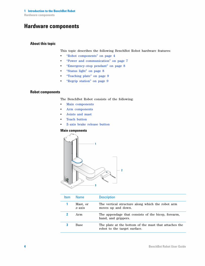
Main components
1
2
3
Item Name Description
1 Mast, or z- axis
The vertical structure along which the robot arm moves up and down.
2 Arm The appendage that consists of the bicep, forearm, hand, and grippers.
3 Base The plate at the bottom of the mast that attaches the robot to the target surface.
4 BenchBot Robot User Guide

1 Introduction to the BenchBot RobotHardware components
Arm components
Joints and mast
4
5
6
7
Item Name Description
4 Bicep The upper segment of the arm that moves up and down along the mast.
5 Forearm The lower segment of the arm that rotates about the elbow.
6 Hand The component of the robot that rotates about the wrist.
7 Grippers The two finger- like structures that open and close to pick up or place labware.
9
8
10
11
Item Name Description
8 Shoulder The joint that connects the robot arm to the mast. The arm rotates 186° about the shoulder.
9 Elbow The joint that connects the bicep and the forearm. The forearm rotates 336° about the elbow.
10 Wrist The joint that connects the forearm to the hand. The hand rotates to any angle about the wrist.
5BenchBot Robot User Guide

1 Introduction to the BenchBot RobotHardware components
Teach button
Z-axis brake release button
11 Mast, or z- axis
The vertical structure along which the robot arm moves up and down.
Item Name Description
12
Item Name Description
12 Teach button
The button at the top of the robot hand allows you to set teachpoints. The button also allows you to grip and release labware in the teach mode. For instructions on how to set teachpoints, see “Setting teachpoints” on page 41.
13
Item Name Description
13 Z- axis brake release button
The button below the bicep that turns off the z- axis brake and allows you to move the robot arm manually along the z- axis.
WARNING The robot arm weighs approximately 7.5 kg (16.5 lb). Be sure to support the weight of the robot arm when pressing the button. Failure to do so will allow the robot arm to fall freely, possibly causing personal injury or damage to another device.
6 BenchBot Robot User Guide
1 Introduction to the BenchBot RobotHardware components
Power and communication
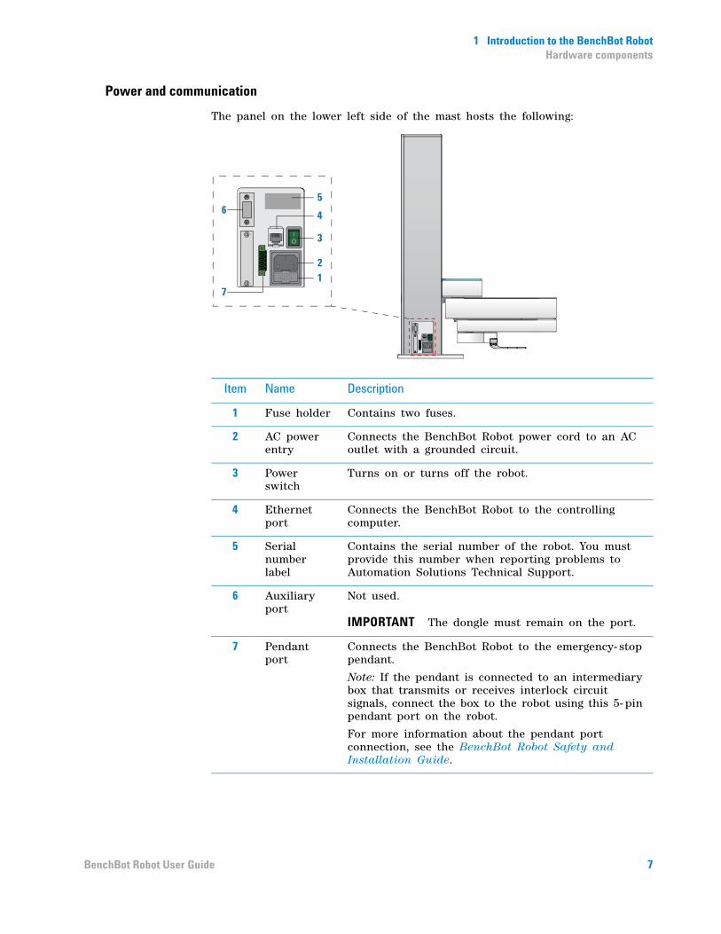
The panel on the lower left side of the mast hosts the following:
2
71
3
465
Item Name Description
1 Fuse holder Contains two fuses.
2 AC power entry
Connects the BenchBot Robot power cord to an AC outlet with a grounded circuit.
3 Power switch
Turns on or turns off the robot.
4 Ethernet port
Connects the BenchBot Robot to the controlling computer.
5 Serial number label
Contains the serial number of the robot. You must provide this number when reporting problems to Automation Solutions Technical Support.
6 Auxiliary port
Not used.
IMPORTANT The dongle must remain on the port.
7 Pendant port
Connects the BenchBot Robot to the emergency- stop pendant.
Note: If the pendant is connected to an intermediary box that transmits or receives interlock circuit signals, connect the box to the robot using this 5- pin pendant port on the robot.
For more information about the pendant port connection, see the BenchBot Robot Safety and Installation Guide.
7BenchBot Robot User Guide
1 Introduction to the BenchBot RobotHardware components
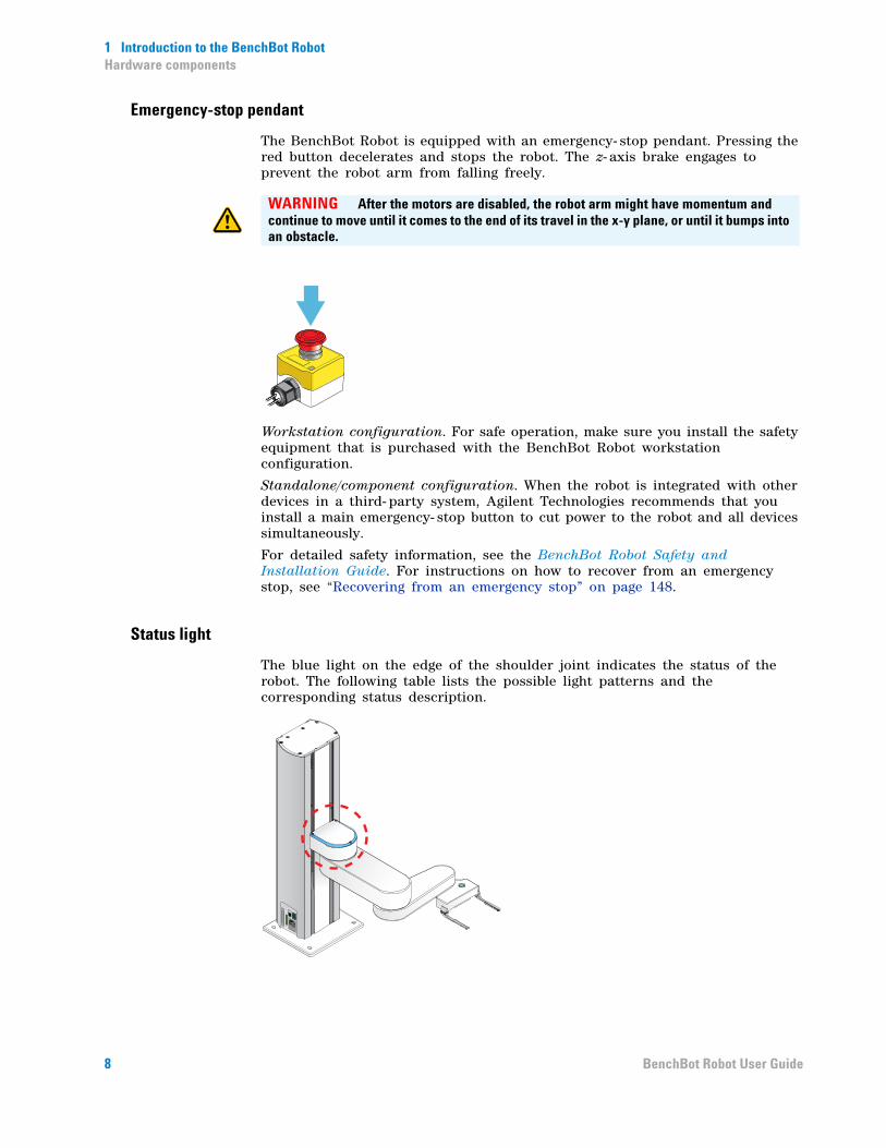
Emergency-stop pendant
The BenchBot Robot is equipped with an emergency- stop pendant. Pressing the red button decelerates and stops the robot. The z- axis brake engages to prevent the robot arm from falling freely.
Workstation configuration. For safe operation, make sure you install the safety equipment that is purchased with the BenchBot Robot workstation configuration.
Standalone/component configuration. When the robot is integrated with other devices in a third- party system, Agilent Technologies recommends that you install a main emergency- stop button to cut power to the robot and all devices simultaneously.
For detailed safety information, see the BenchBot Robot Safety and Installation Guide. For instructions on how to recover from an emergency stop, see “Recovering from an emergency stop” on page 148.
Status light
The blue light on the edge of the shoulder joint indicates the status of the robot. The following table lists the possible light patterns and the corresponding status description.
WARNING After the motors are disabled, the robot arm might have momentum and continue to move until it comes to the end of its travel in the x-y plane, or until it bumps into an obstacle.
8 BenchBot Robot User Guide

1 Introduction to the BenchBot RobotHardware components
Teaching plate
Supplied with the BenchBot Robot, the teaching plate allows you to set teachpoints quickly and accurately. The teaching plate can be used for setting teachpoints in the landscape (1) or portrait orientation (2).
For instructions on how to use the teaching plate to set teachpoints, see “Setting teachpoints” on page 41.
Note: Most device locations can be taught using the teaching plate. However, if size restrictions at a teachpoint prevent the use of the teaching plate, you can use the labware intended for the location. For more information, see “Setting teachpoints using a labware” on page 70.
Regrip station
A regrip station is a platepad that the robot uses to:
• Change the labware (landscape/portrait) or A1- well orientation between teachpoints that require different orientations.
• Adjust its grip to the specified labware gripping height. The location is typically used after a robot picks up a labware lower than the specified gripping height because of physical restrictions at a teachpoint.
Light pattern Description
Solid blue The robot power is on, but the robot motors are disabled.
Blinking blue The robot power is on, and the robot motors are enabled. The blinking blue light also indicates one of the following:
• The robot is moving.
• The robot is in the teach mode.
1 2
9BenchBot Robot User Guide

1 Introduction to the BenchBot RobotHardware components
Related information
For information about... See...
BenchBot Robot description “About the BenchBot Robot” on page 2
Robot specifications BenchBot Robot Safety and Installation Guide
Safety information BenchBot Robot Safety and Installation Guide
10 BenchBot Robot User Guide
1 Introduction to the BenchBot RobotDevice integration options
Device integration options
About devices and integration plates
Devices are individual pieces of equipment that are integrated in a system or workstation. Typically, devices store or process labware. For example, the Plate Hotel stores labware, and the Bravo Platform processes labware.
This topic lists the devices that can be integrated with the BenchBot Robot:
• Agilent Technologies devices
• Third- party devices
In addition, this topic explains the use of the BenchBot Robot integration plates. See BenchBot integration plates.
Agilent Technologies devices
Labware- processing devices that can be integrated in a system or workstation with the BenchBot Robot include:
• Bravo Platform
• Microplate Centrifuge
• Microplate Labeler
• PlateLoc Sealer
• Seal Piercer
• Vertical Pipetting Station
A number of other devices that store labware or permit the stacking of devices can also be integrated with the BenchBot Robot. For a comprehensive list of these devices, contact Automation Solutions Customer Service. For instructions on how to install and configure the device to work with the BenchBot Robot, see the device user guide.
Third-party devices
Many third- party devices can be integrated to work with the BenchBot Robot. For a comprehensive list, contact Automation Solutions Customer Service.
BenchBot integration plates
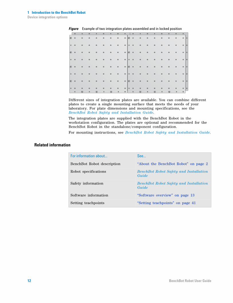
The BenchBot integration plates are flat, metal plates that provide a stable mounting surface for the BenchBot Robot and other devices. The position and number of mounting holes in the plates accommodate a large variety of device configurations. In addition, the plates have locking mechanisms that keep the robot and devices in position during protocol runs.
11BenchBot Robot User Guide
1 Introduction to the BenchBot RobotDevice integration options
Figure Example of two integration plates assembled and in locked position
Different sizes of integration plates are available. You can combine different plates to create a single mounting surface that meets the needs of your laboratory. For plate dimensions and mounting specifications, see the BenchBot Robot Safety and Installation Guide.
The integration plates are supplied with the BenchBot Robot in the workstation configuration. The plates are optional and recommended for the BenchBot Robot in the standalone/component configuration.
For mounting instructions, see BenchBot Robot Safety and Installation Guide.
Related information
For information about... See...
BenchBot Robot description “About the BenchBot Robot” on page 2
Robot specifications BenchBot Robot Safety and Installation Guide
Safety information BenchBot Robot Safety and Installation Guide
Software information “Software overview” on page 13
Setting teachpoints “Setting teachpoints” on page 41
12 BenchBot Robot User Guide

1 Introduction to the BenchBot RobotSoftware overview
Software overview
About this topic
This topic describes the software components you use to operate the BenchBot Robot:
• “BenchBot Robot Diagnostics software” on page 13
• “VWorks software” on page 14
BenchBot Robot Diagnostics software
The BenchBot Robot Diagnostics software allows you to:
• Configure the robot. You create a robot profile to set up communication between the robot and the controlling computer. You create the profile when you set up the robot. For setup information, see “Setting up the BenchBot Robot” on page 19.
• Set and edit teachpoints. Teachpoints are locations that the BenchBot Robot will go to and from during a protocol run. You set teachpoints when you set up the BenchBot Robot. You can also edit the teachpoints to correct or fine-tune the original teachpoints. For teachpoint setup and editing information, see “Setting teachpoints” on page 1.
• Diagnose problems. Moving and adjusting individual hardware components allow you to diagnose and troubleshoot problems. For information on diagnosing and troubleshooting problems, see “Using BenchBot Diagnostics” on page 97.
You can access BenchBot Robot Diagnostics from within the VWorks software only. For more information, see “VWorks software” on page 14.
13BenchBot Robot User Guide
1 Introduction to the BenchBot RobotSoftware overview
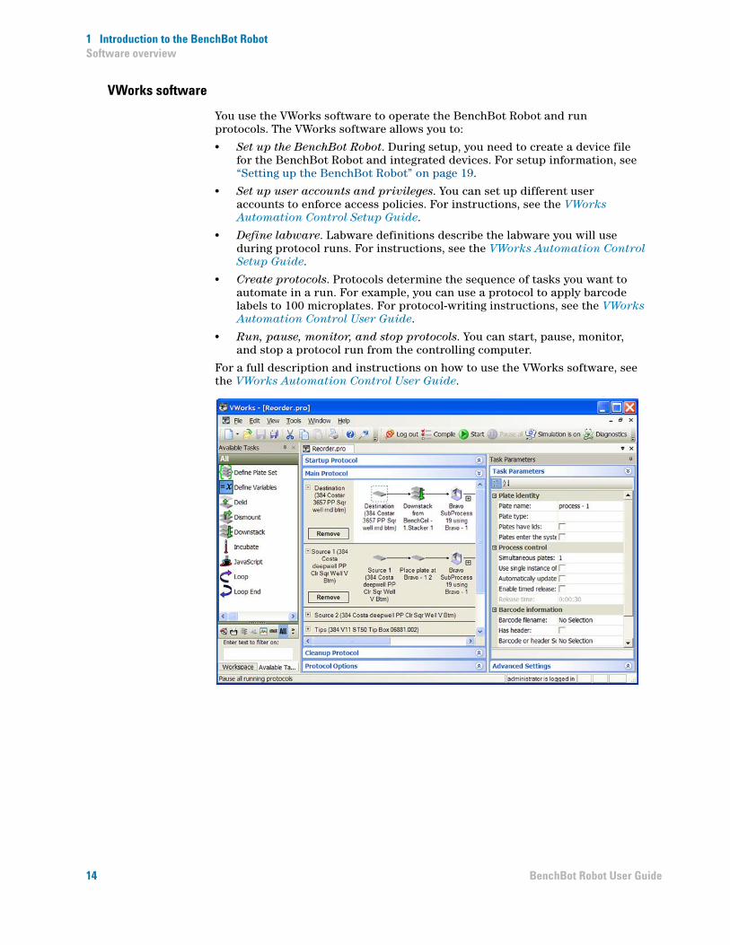
VWorks software
You use the VWorks software to operate the BenchBot Robot and run protocols. The VWorks software allows you to:
• Set up the BenchBot Robot. During setup, you need to create a device file for the BenchBot Robot and integrated devices. For setup information, see “Setting up the BenchBot Robot” on page 19.
• Set up user accounts and privileges. You can set up different user accounts to enforce access policies. For instructions, see the VWorks Automation Control Setup Guide.
• Define labware. Labware definitions describe the labware you will use during protocol runs. For instructions, see the VWorks Automation Control Setup Guide.
• Create protocols. Protocols determine the sequence of tasks you want to automate in a run. For example, you can use a protocol to apply barcode labels to 100 microplates. For protocol-writing instructions, see the VWorks Automation Control User Guide.
• Run, pause, monitor, and stop protocols. You can start, pause, monitor, and stop a protocol run from the controlling computer.
For a full description and instructions on how to use the VWorks software, see the VWorks Automation Control User Guide.
14 BenchBot Robot User Guide
1 Introduction to the BenchBot RobotSoftware overview
Related information
For information about... See...
VWorks software instructions VWorks Automation Control User Guide
BenchBot Robot description “About the BenchBot Robot” on page 2
Robot specifications BenchBot Robot Safety and Installation Guide
Hardware components “Hardware components” on page 4
15BenchBot Robot User Guide
1 Introduction to the BenchBot RobotQuick start
Quick start
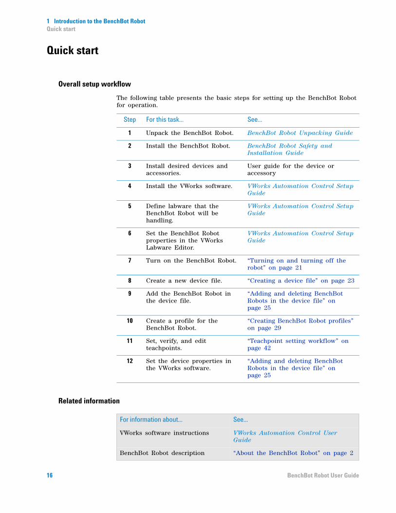
Overall setup workflow
The following table presents the basic steps for setting up the BenchBot Robot for operation.
Related information
Step For this task... See...
1 Unpack the BenchBot Robot. BenchBot Robot Unpacking Guide
2 Install the BenchBot Robot. BenchBot Robot Safety and Installation Guide
3 Install desired devices and accessories.
User guide for the device or accessory
4 Install the VWorks software. VWorks Automation Control Setup Guide
5 Define labware that the BenchBot Robot will be handling.
VWorks Automation Control Setup Guide
6 Set the BenchBot Robot properties in the VWorks Labware Editor.
VWorks Automation Control Setup Guide
7 Turn on the BenchBot Robot. “Turning on and turning off the robot” on page 21
8 Create a new device file. “Creating a device file” on page 23
9 Add the BenchBot Robot in the device file.
“Adding and deleting BenchBot Robots in the device file” on page 25
10 Create a profile for the BenchBot Robot.
“Creating BenchBot Robot profiles” on page 29
11 Set, verify, and edit teachpoints.
“Teachpoint setting workflow” on page 42
12 Set the device properties in the VWorks software.
“Adding and deleting BenchBot Robots in the device file” on page 25
For information about... See...
VWorks software instructions VWorks Automation Control User Guide
BenchBot Robot description “About the BenchBot Robot” on page 2
16 BenchBot Robot User Guide

1 Introduction to the BenchBot RobotQuick start
Robot specifications BenchBot Robot Safety and Installation Guide
Hardware components “Hardware components” on page 4
For information about... See...
17BenchBot Robot User Guide

1 Introduction to the BenchBot RobotQuick start
18 BenchBot Robot User Guide

BenchBot RobotUser Guide
2Setting up the BenchBot Robot
This chapter explains how to set up the BenchBot Robot using the VWorks software and BenchBot Diagnostics.
This chapter contains the following topics:
• “Setup workflow” on page 20
• “Turning on and turning off the robot” on page 21
• “Creating a device file” on page 23
• “Adding and deleting BenchBot Robots in the device file” on page 25
• “Creating BenchBot Robot profiles” on page 29
• “Setting up robot communication” on page 31
• “Selecting a teachpoint file” on page 34
• “Saving the profile” on page 36
• “Initializing the profile” on page 37
• “Editing and managing profiles” on page 39
WARNING Only administrators and experienced personnel should perform the procedures in this chapter.
19

2 Setting up the BenchBot RobotSetup workflow
Setup workflow
About this topic
This topic presents the workflow for setting up the BenchBot Robot for operation.
Workflow
The following table presents the steps for setting up the BenchBot Robot. After setting up the BenchBot Robot for the first time, you will not likely change any of the settings in the procedure.
If you want to edit, delete, rename, or create a new profile using an existing profile, see “Editing and managing profiles” on page 39.
Related information
Step For this task... See...
1 Turn on the robot. “Turning on and turning off the robot” on page 21
2 Create a device file. “Creating a device file” on page 23
3 Add the BenchBot Robot in the device file.
“Adding and deleting BenchBot Robots in the device file” on page 25.
4 Create a profile for the BenchBot Robot.
“Creating BenchBot Robot profiles” on page 29
5 Set up robot communication. “Setting up robot communication” on page 31
6 Select a teachpoint file. “Selecting a teachpoint file” on page 34
7 Save the profile. “Saving the profile” on page 36
8 Initialize the profile. “Initializing the profile” on page 37
9 Back up the firmware. “Backing up the robot firmware” on page 129
For information about... See...
Installing the robot BenchBot Robot Safety and Installation Guide
Teachpoint files “Teachpoint files” on page 51
Setting teachpoints “Setting teachpoints” on page 41
20 BenchBot Robot User Guide

2 Setting up the BenchBot RobotTurning on and turning off the robot
Turning on and turning off the robot
Turning on the BenchBot Robot
To turn on the robot:
At the lower left side of the mast, press the power switch to the on ( I ) position.
After 30 seconds, the blue light at the shoulder starts to blink. The blinking light indicates that the controller and software have successfully started. After the startup procedure is finished, the blue light stays on and stops blinking. If the blue light does not turn on, see “Troubleshooting robot problems” on page 147.
The entire startup process takes approximately 1 minute. During this time, the robot does not move.
Turning off the BenchBot Robot
IMPORTANT If you will be packing the robot for storage or shipment, you must first home the robot before turning off its power. Homing the robot moves the arm to a position that is optimal for packing. To home the robot, see “Homing the robot and grippers” on page 103.
To turn off the robot:
1 Disable the robot motors. You can either press the red button on the emergency- stop pendant, or you can click the Stop Motors button in BenchBot Diagnostics.
21BenchBot Robot User Guide

2 Setting up the BenchBot RobotTurning on and turning off the robot
2 At the lower left side of the mast, press the power switch to the off ( O ) position. The light at the shoulder and on the robot hand turn off.
Related information
For information about... See...
Installing the VWorks software VWorks Automation Control Setup Guide
Stopping the robot motors using the Stop Motors command in BenchBot Diagnostics
“Stopping the robot motors” on page 115
Adding the robot to a device file “Adding and deleting BenchBot Robots in the device file” on page 25
Creating profiles for the robot “Creating BenchBot Robot profiles” on page 29
Setting teachpoints “Setting teachpoints” on page 41
Installing the robot BenchBot Robot Safety and Installation Guide
Removing the robot from the attachment surface
BenchBot Robot Safety and Installation Guide
Packing the robot BenchBot Robot Unpacking Guide
22 BenchBot Robot User Guide
2 Setting up the BenchBot RobotCreating a device file
Creating a device file
About this topic
This topic explains how to create a device file, and add and delete the BenchBot Robot in the device file.
Devices and device file defined
What is a device?A device is an item in your lab automation system that has an entry in the VWorks software device file. A device can be a robot, an instrument, or a location in the system that can hold a piece of labware. The following are some examples of devices:
• BenchBot Robot
• Bravo Platform
• Microplate Labeler
• Platepad
• A third- party device
What is a device file?To communicate with and to control the robot and integrated devices, the VWorks software uses a device file that contains the following information:
• List of devices the software will communicate with and control
• Profile of each device (communication method, unique device configuration information)
• Properties of each device (for example, barcode access)
You provide the device information in the VWorks software. The device information is stored in a device (.dev) file that is located in a folder you specify when saving the file.
For detailed information about device files and associations with profiles, teachpoint files, and other VWorks components, see the VWorks Automation Control User Guide.
Procedure
If you are setting up the BenchBot Robot for the first time, you need to create a new device file, and then add the BenchBot Robot and integrated devices to this file.
Before you create a device file, start the VWorks software and log in. See the VWorks Automation Control User Guide for instructions.
23BenchBot Robot User Guide

2 Setting up the BenchBot RobotCreating a device file
To create a new device file:
1 In the VWorks window, select File > New > Device. A Device File tab appears.
2 Select File > Save to save the device file. The file name appears in the Device File tab.
Related information
For information about... See...
VWorks software • VWorks Automation Control Setup Guide
• VWorks Automation Control User Guide
Adding the BenchBot Robot in the device file
“Adding and deleting BenchBot Robots in the device file” on page 25
Creating profiles for the robot “Creating BenchBot Robot profiles” on page 29
Setting teachpoints “Setting teachpoints” on page 41
24 BenchBot Robot User Guide

2 Setting up the BenchBot RobotAdding and deleting BenchBot Robots in the device file
Adding and deleting BenchBot Robots in the device file
Adding BenchBot Robots in the device file
To add a BenchBot Robot in the device file:
1 In the Available Devices area, double- click the BenchBot Robot device icon. Alternatively, you can drag the icon from the Available Devices area into the Device File area.
Notice that the first BenchBot Robot device is labeled BenchBot Robot- 1. If you add another BenchBot Robot device, it will appear as BenchBot Robot-2.
If you do not see BenchBot Robot in the Available Devices list, check that the BenchBot plugin file (BenchBot Robot.dll) is stored in the following folder: ...\Agilent Technologies\VWorks\Plugins folder.
If you added the BenchBot Robot plugin file in the Plugins folder and you have already started the VWorks software, be sure to reload the plugin. To do this, close any open device files and protocol files, and then select Tools > Reload Plugins.
25BenchBot Robot User Guide

2 Setting up the BenchBot RobotAdding and deleting BenchBot Robots in the device file
2 In the device properties area, type a Name for the device.
In the following example, the name for the BenchBot Robot is My BenchBot Robot.
3 Select the Profile.
If the profile you want does not appear in the list, or if no profile appears in the list, you need to:
a Create the profile. See “Creating BenchBot Robot profiles” on page 29.
b Set up robot communication. See “Setting up robot communication” on page 31.
c Select a teachpoint file. See “Selecting a teachpoint file” on page 34.
d Save the profile. See “Saving the profile” on page 36.
26 BenchBot Robot User Guide

2 Setting up the BenchBot RobotAdding and deleting BenchBot Robots in the device file
e Initialize the profile. See “Initializing the profile” on page 37.
f Return to this step to select the profile.
Without the profile, you will not be able to establish communication with the device.
4 If you have multiple BenchBot Robots in the system, repeat steps 1 through 3 to add another BenchBot Robot.
5 Select File > Save to save the device file.
6 In the Device File area, select the BenchBot Robot, and then click Initialize selected devices to establish communication with the robot.
If an initialization error message appears, see “Resolving robot initialization errors” on page 150 for instructions.
Deleting a BenchBot Robot from the device file
To delete a BenchBot Robot from the device file:
1 In the VWorks window, select the BenchBot Robot you want to delete in the Devices area.
2 Click Delete selected devices.
Related information
For information about... See...
VWorks software • VWorks Automation Control Setup Guide
• VWorks Automation Control User Guide
Creating profiles for the robot “Creating BenchBot Robot profiles” on page 29
27BenchBot Robot User Guide
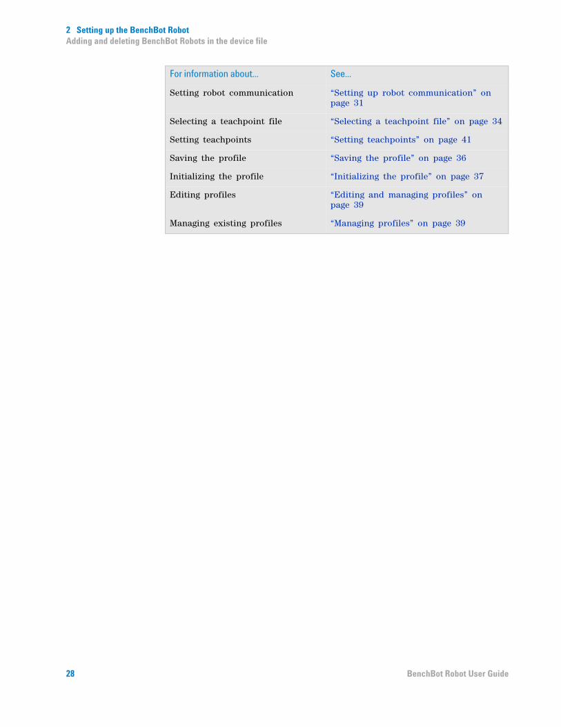
2 Setting up the BenchBot RobotAdding and deleting BenchBot Robots in the device file
Setting robot communication “Setting up robot communication” on page 31
Selecting a teachpoint file “Selecting a teachpoint file” on page 34
Setting teachpoints “Setting teachpoints” on page 41
Saving the profile “Saving the profile” on page 36
Initializing the profile “Initializing the profile” on page 37
Editing profiles “Editing and managing profiles” on page 39
Managing existing profiles “Managing profiles” on page 39
For information about... See...
28 BenchBot Robot User Guide

2 Setting up the BenchBot RobotCreating BenchBot Robot profiles
Creating BenchBot Robot profiles
About this topic
This topic explains how to create a new profile for the BenchBot Robot and how to manage existing profiles. For instructions on how to create profiles for other Agilent Technologies devices, see the corresponding device user documentation. For instructions on how to create profiles for third- party device, see the third- party device driver user guide.
About profiles
IMPORTANT Each device in the device file requires a unique profile.
A profile is a collection of settings, stored in the Windows registry, that manages how you connect to a device. A profile:
• Specifies the port or IP address used to establish communication between the device and the controlling computer.
• References a teachpoint file. For a description of teachpoint files, see “Setting teachpoints” on page 41.
You use the BenchBot Diagnostics software to create and manage BenchBot Robot profiles.
Note: The profile is referenced by a device file. For information about device files, see “What is a device file?” on page 23. For a detailed description of the relationships between the device file, profile, and teachpoint file, see the VWorks Automation Control User Guide.
Creating a BenchBot Robot profile
To create a BenchBot Robot profile:
1 In the Devices area, select the BenchBot Robot device, and then click Device diagnostics.
29BenchBot Robot User Guide

2 Setting up the BenchBot RobotCreating BenchBot Robot profiles
The BenchBot Diagnostics dialog box opens.
2 If it is not already displayed, click the Profiles tab.
3 In the Profile Management area, click Create a new profile. The Create Profile dialog box opens.
4 Type a name, and click OK. The name appears in the Profile Management area.
Related information
For information about... See...
Setting robot communication “Setting up robot communication” on page 31
Selecting a teachpoint file “Selecting a teachpoint file” on page 34
Setting teachpoints “Setting teachpoints” on page 41
Saving the profile “Saving the profile” on page 36
Initializing the profile “Initializing the profile” on page 37
Editing profiles “Editing and managing profiles” on page 39
Managing existing profiles “Managing profiles” on page 39
30 BenchBot Robot User Guide

2 Setting up the BenchBot RobotSetting up robot communication
Setting up robot communication
About this topic
When you create a profile, you must also select the robot with which to establish communication. This topic explains how to locate the robot in the system network.
If you have more than one BenchBot Robot in the system
Every device in the system must have a unique IP address for proper operation. All BenchBot Robots are assigned the same IP address at the factory. Therefore, if you have more than one BenchBot Robot installed in the system, you must make sure each is assigned a unique IP address. You can do this when creating a profile for the robot.
Procedure
To set up robot communication:
1 In the Robot Identifiers area, click Find Available BenchBot Robots.
31BenchBot Robot User Guide

2 Setting up the BenchBot RobotSetting up robot communication
2 In the Find BenchBot Robots dialog box that opens, select the BenchBot Robot to which you want to connect:
Step Instruction
1 In the Network Adaptors list, select the Ethernet card that is connected to the robot. A list of devices that are connected to the selected card appear in the dialog box.
2 Select the desired BenchBot Robot. You can use the MAC address to identify the robot in the list.
To correctly identify a robot by its MAC address, you might need to turn off all devices and all but one robot in the system.
3 If you have more than one BenchBot Robot in the system, make sure each robot has a unique IP address. To do this, turn off all but one robot in the system, select the robot in this dialog box, click Change Robot IP Address, and then assign a new IP address. The IP address should have the same network and subnet address as the controlling computer, and have a unique host address. Repeat for each robot in the system.
32 BenchBot Robot User Guide
2 Setting up the BenchBot RobotSetting up robot communication
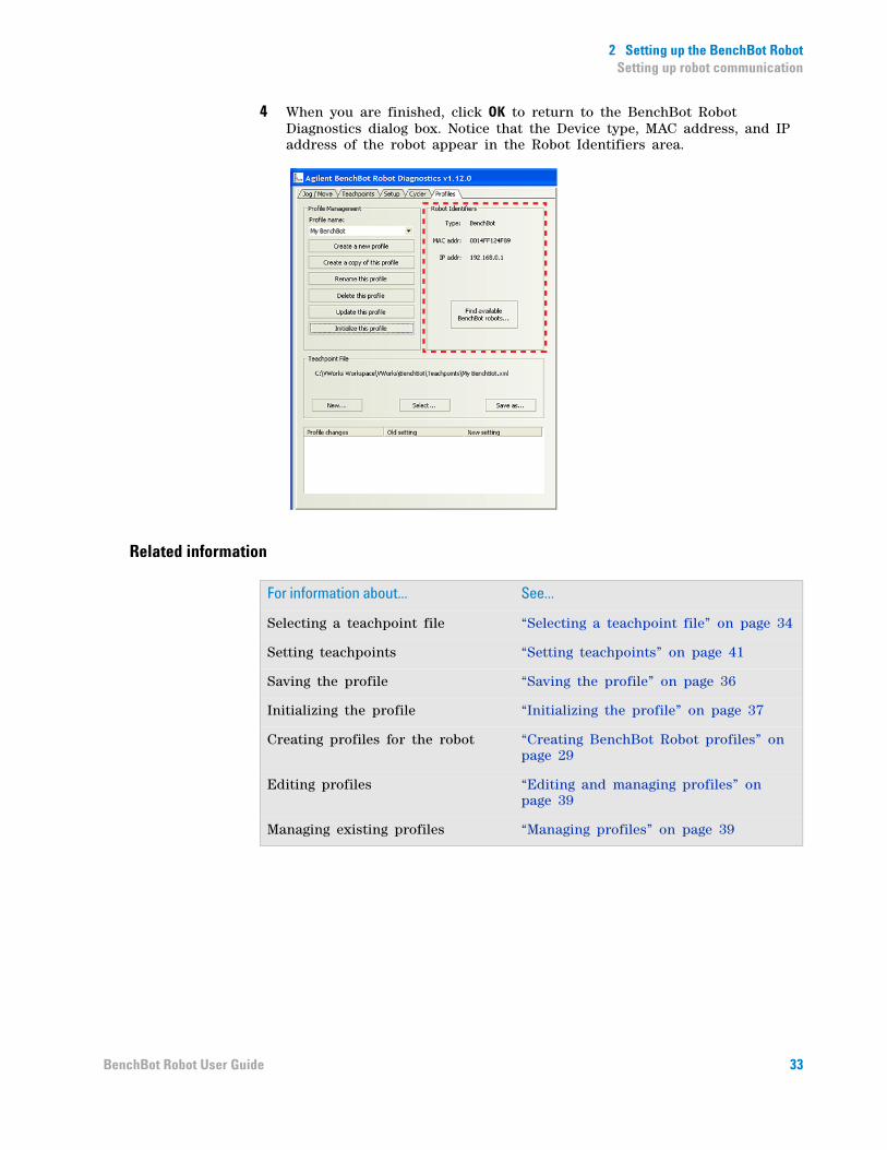
4 When you are finished, click OK to return to the BenchBot Robot Diagnostics dialog box. Notice that the Device type, MAC address, and IP address of the robot appear in the Robot Identifiers area.
Related information
For information about... See...
Selecting a teachpoint file “Selecting a teachpoint file” on page 34
Setting teachpoints “Setting teachpoints” on page 41
Saving the profile “Saving the profile” on page 36
Initializing the profile “Initializing the profile” on page 37
Creating profiles for the robot “Creating BenchBot Robot profiles” on page 29
Editing profiles “Editing and managing profiles” on page 39
Managing existing profiles “Managing profiles” on page 39
33BenchBot Robot User Guide
2 Setting up the BenchBot RobotSelecting a teachpoint file
Selecting a teachpoint file
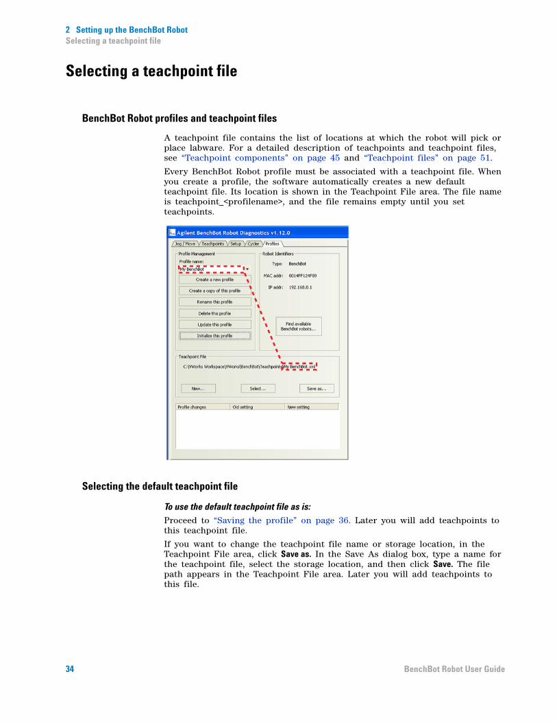
BenchBot Robot profiles and teachpoint files
A teachpoint file contains the list of locations at which the robot will pick or place labware. For a detailed description of teachpoints and teachpoint files, see “Teachpoint components” on page 45 and “Teachpoint files” on page 51.
Every BenchBot Robot profile must be associated with a teachpoint file. When you create a profile, the software automatically creates a new default teachpoint file. Its location is shown in the Teachpoint File area. The file name is teachpoint_<profilename>, and the file remains empty until you set teachpoints.
Selecting the default teachpoint file
To use the default teachpoint file as is:
Proceed to “Saving the profile” on page 36. Later you will add teachpoints to this teachpoint file.
If you want to change the teachpoint file name or storage location, in the Teachpoint File area, click Save as. In the Save As dialog box, type a name for the teachpoint file, select the storage location, and then click Save. The file path appears in the Teachpoint File area. Later you will add teachpoints to this file.
34 BenchBot Robot User Guide
2 Setting up the BenchBot RobotSelecting a teachpoint file
Selecting an existing teachpoint file
If you want to use an existing teachpoint file:
In the Teachpoint File area, click Select. In the Select a Teachpoint File dialog box, locate and select the teachpoint file that you want to use, and then click Open. The file path appears in the Teachpoint File area.
If you want to use an existing teachpoint file and rename it, you must select the existing teachpoint file, initialize the profile to load information in the existing teachpoint file (“Initializing the profile” on page 37), and then click Save As in the Teachpoint File area to rename it.
Related information
CAUTION If the teachpoint file was copied from another computer, you must verify the teachpoints for the new profile before using it.
For information about... See...
Setting teachpoints “Setting teachpoints” on page 41
Saving the profile “Saving the profile” on page 36
Initializing the profile “Initializing the profile” on page 37
Creating profiles for the robot “Creating BenchBot Robot profiles” on page 29
Setting up robot communication “Setting up robot communication” on page 31
Editing profiles “Editing and managing profiles” on page 39
Managing existing profiles “Managing profiles” on page 39
35BenchBot Robot User Guide
2 Setting up the BenchBot RobotSaving the profile
Saving the profile
Procedure
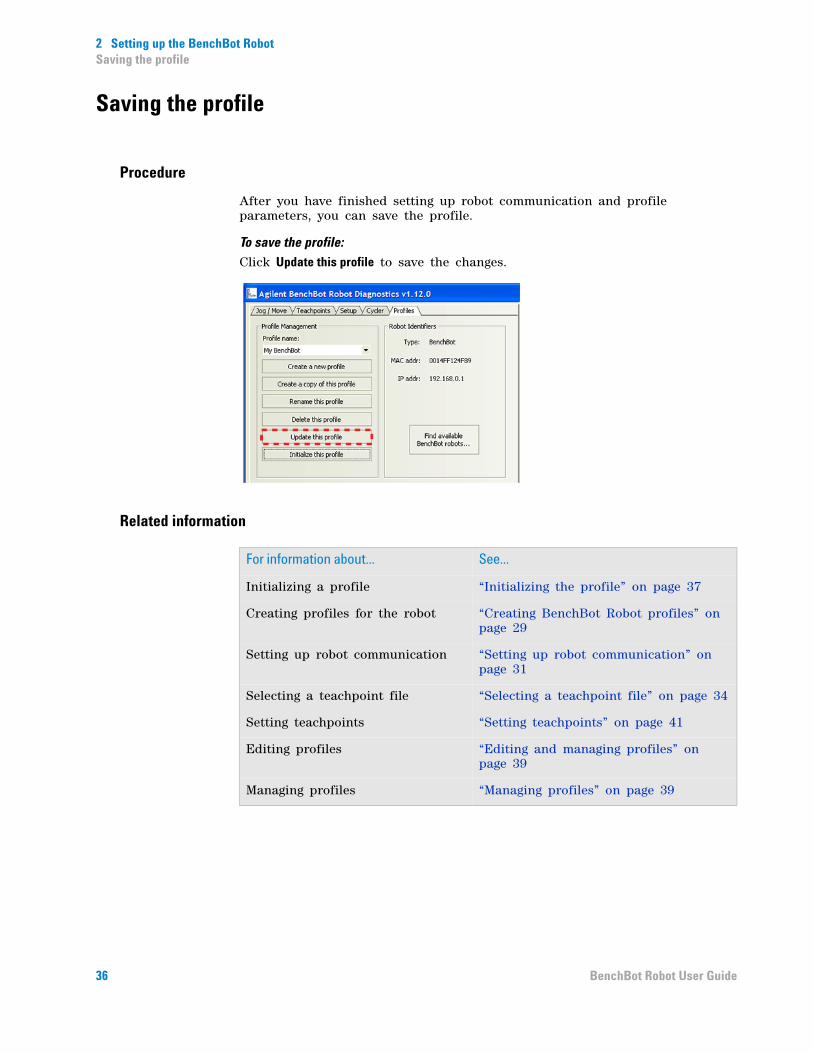
After you have finished setting up robot communication and profile parameters, you can save the profile.
To save the profile:Click Update this profile to save the changes.
Related information
For information about... See...
Initializing a profile “Initializing the profile” on page 37
Creating profiles for the robot “Creating BenchBot Robot profiles” on page 29
Setting up robot communication “Setting up robot communication” on page 31
Selecting a teachpoint file “Selecting a teachpoint file” on page 34
Setting teachpoints “Setting teachpoints” on page 41
Editing profiles “Editing and managing profiles” on page 39
Managing profiles “Managing profiles” on page 39
36 BenchBot Robot User Guide
2 Setting up the BenchBot RobotInitializing the profile
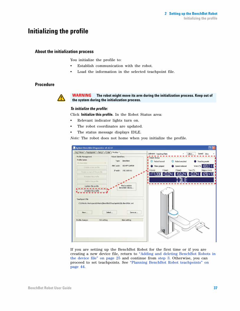
Initializing the profile
About the initialization process
You initialize the profile to:
• Establish communication with the robot.
• Load the information in the selected teachpoint file.
Procedure
To initialize the profile:
Click Initialize this profile. In the Robot Status area:
• Relevant indicator lights turn on.
• The robot coordinates are updated.
• The status message displays IDLE.
Note: The robot does not home when you initialize the profile.
If you are setting up the BenchBot Robot for the first time or if you are creating a new device file, return to “Adding and deleting BenchBot Robots in the device file” on page 25 and continue from step 3. Otherwise, you can proceed to set teachpoints. See “Planning BenchBot Robot teachpoints” on page 44.
WARNING The robot might move its arm during the initialization process. Keep out of the system during the initialization process.
37BenchBot Robot User Guide

2 Setting up the BenchBot RobotInitializing the profile
Related information
For information about... See...
Creating profiles for the robot “Creating BenchBot Robot profiles” on page 29
Setting up robot communication “Setting up robot communication” on page 31
Selecting a teachpoint file “Selecting a teachpoint file” on page 34
Saving the profile “Saving the profile” on page 36
Setting teachpoints “Setting teachpoints” on page 41
Editing profiles “Editing and managing profiles” on page 39
Managing profiles “Managing profiles” on page 39
38 BenchBot Robot User Guide
2 Setting up the BenchBot RobotEditing and managing profiles
Editing and managing profiles
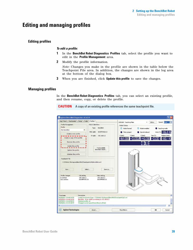
Editing profiles
To edit a profile:
1 In the BenchBot Robot Diagnostics Profiles tab, select the profile you want to edit in the Profile Management area.
2 Modify the profile information.
Note: Changes you make in the profile are shown in the table below the Teachpoint File area. In addition, the changes are shown in the log area at the bottom of the dialog box.
3 When you are finished, click Update this profile to save the changes.
Managing profiles
In the BenchBot Robot Diagnostics Profiles tab, you can select an existing profile, and then rename, copy, or delete the profile.
CAUTION A copy of an existing profile references the same teachpoint file.
39BenchBot Robot User Guide
2 Setting up the BenchBot RobotEditing and managing profiles
Related information
For information about... See...
Creating profiles for the robot “Creating BenchBot Robot profiles” on page 29
Setting up robot communication “Setting up robot communication” on page 31
Selecting a teachpoint file “Selecting a teachpoint file” on page 34
Saving the profile “Saving the profile” on page 36
Initializing the profile “Initializing the profile” on page 37
Setting teachpoints “Setting teachpoints” on page 41
Editing profiles “Editing and managing profiles” on page 39
40 BenchBot Robot User Guide
BenchBot RobotUser Guide
3Setting teachpoints
This chapter explains how to set BenchBot Robot teachpoints using BenchBot Diagnostics.
This chapter contains the following topics:
• “Teachpoint setting workflow” on page 42
• “Planning BenchBot Robot teachpoints” on page 44
• “Setting new teachpoints” on page 51
• “Specifying the A1- well orientation” on page 57
• “Selecting the teachpoint type” on page 59
• “Setting the Approach Height and Approach Distance parameters” on page 61
• “Setting the Min and Max Gripper Offset parameters” on page 65
• “Setting the X, Y, Z, and Yaw parameters” on page 67
• “Adding multiple orientations to a teachpoint” on page 68
• “Saving the teachpoints” on page 69
• “Setting teachpoints using a labware” on page 70
• “Verifying teachpoints” on page 71
• “Editing existing teachpoints” on page 81
• “Managing teachpoints” on page 86
• “Cycling teachpoints” on page 87
WARNING Only administrators and experienced personnel should perform the procedures in this chapter.
41
3 Setting teachpointsTeachpoint setting workflow
Teachpoint setting workflow
About this topic
This topic presents the workflow for setting BenchBot Robot teachpoints.
Workflow
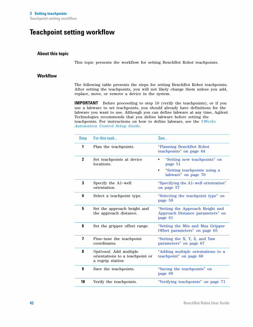
The following table presents the steps for setting BenchBot Robot teachpoints. After setting the teachpoints, you will not likely change them unless you add, replace, move, or remove a device in the system.
IMPORTANT Before proceeding to step 10 (verify the teachpoints), or if you use a labware to set teachpoints, you should already have definitions for the labware you want to use. Although you can define labware at any time, Agilent Technologies recommends that you define labware before setting the teachpoints. For instructions on how to define labware, see the VWorks Automation Control Setup Guide.
Step For this task... See...
1 Plan the teachpoints. “Planning BenchBot Robot teachpoints” on page 44
2 Set teachpoints at device locations.
• “Setting new teachpoints” on page 51
• “Setting teachpoints using a labware” on page 70
3 Specify the A1- well orientation.
“Specifying the A1- well orientation” on page 57
4 Select a teachpoint type. “Selecting the teachpoint type” on page 59
5 Set the approach height and the approach distance.
“Setting the Approach Height and Approach Distance parameters” on page 61
6 Set the gripper offset range. “Setting the Min and Max Gripper Offset parameters” on page 65
7 Fine- tune the teachpoint coordinates.
“Setting the X, Y, Z, and Yaw parameters” on page 67
8 Optional. Add multiple orientations to a teachpoint or a regrip station
“Adding multiple orientations to a teachpoint” on page 68
9 Save the teachpoints. “Saving the teachpoints” on page 69
10 Verify the teachpoints. “Verifying teachpoints” on page 71
42 BenchBot Robot User Guide

3 Setting teachpointsTeachpoint setting workflow
Related information
11 Edit the teachpoints. “Editing existing teachpoints” on page 81
12 Cycle the teachpoints. “Cycling teachpoints” on page 87
Step For this task... See...
For information about... See...
Preparing for protocol runs “Preparing for a protocol run” on page 91
Using diagnostic commands “Using BenchBot Diagnostics” on page 97
Troubleshooting errors “Troubleshooting robot problems” on page 147
43BenchBot Robot User Guide

3 Setting teachpointsPlanning BenchBot Robot teachpoints
Planning BenchBot Robot teachpoints
About this topic
Carefully planned teachpoints can optimize results and throughput. This topic presents the following:
• “About teachpoints” on page 44
• “Teachpoint zone” on page 44
• “Teachpoint components” on page 45
• “Guidelines for setting teachpoints” on page 48
• “Examples” on page 49
About teachpoints
A teachpoint is a set of coordinates that define where the robot picks up or places labware. The teachpoint can be on an integrated device or a platepad.
You set and edit teachpoints in the BenchBot Robot Diagnostics Teachpoints tab.
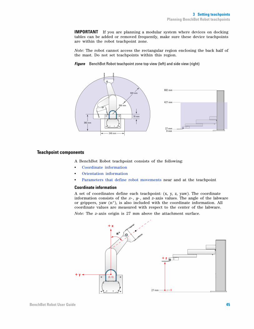
Teachpoint zone
The teachpoint zone is the region within which you can set teachpoints. The following diagram shows the top and side views of the teachpoint zone. The outermost line shows the robot’s maximum reach, through the center of the gripper and labware. The region within the inner line is the the robot zone. The teachpoint zone is between the two boundaries.
44 BenchBot Robot User Guide
3 Setting teachpointsPlanning BenchBot Robot teachpoints
IMPORTANT If you are planning a modular system where devices on docking tables can be added or removed frequently, make sure these device teachpoints are within the robot teachpoint zone.
Note: The robot cannot access the rectangular region enclosing the back half of the mast. Do not set teachpoints within this region.
Figure BenchBot Robot teachpoint zone top view (left) and side view (right)
Teachpoint components
A BenchBot Robot teachpoint consists of the following:
• Coordinate information
• Orientation information
• Parameters that define robot movements near and at the teachpoint
Coordinate informationA set of coordinates define each teachpoint: (x, y, z, yaw). The coordinate information consists of the x- , y- , and z- axis values. The angle of the labware or grippers, yaw (n°), is also included with the coordinate information. All coordinate values are measured with respect to the center of the labware.
Note: The z- axis origin is 27 mm above the attachment surface.
0 mm27 mm
427 mm
682 mm
70 mm
340 mm
594 mm
300 mm
383 mm
+ x
+ y(0, 0)
+ z
n°
z = 027 mm
45BenchBot Robot User Guide
3 Setting teachpointsPlanning BenchBot Robot teachpoints
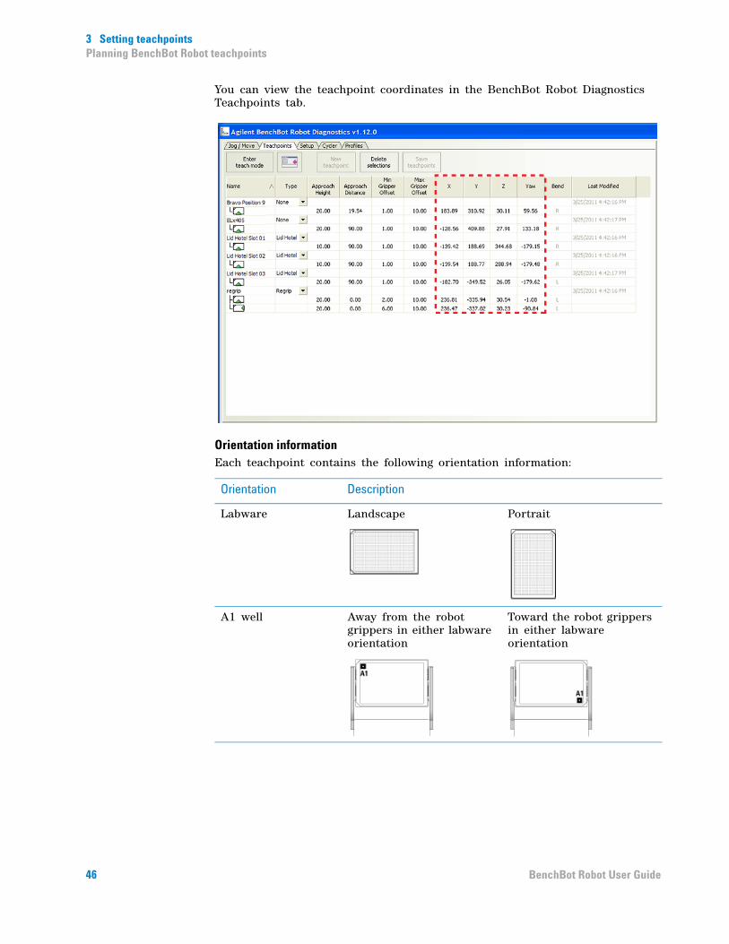
You can view the teachpoint coordinates in the BenchBot Robot Diagnostics Teachpoints tab.
Orientation informationEach teachpoint contains the following orientation information:
Orientation Description
Labware Landscape Portrait
A1 well Away from the robot grippers in either labware orientation
Toward the robot grippers in either labware orientation
46 BenchBot Robot User Guide
3 Setting teachpointsPlanning BenchBot Robot teachpoints
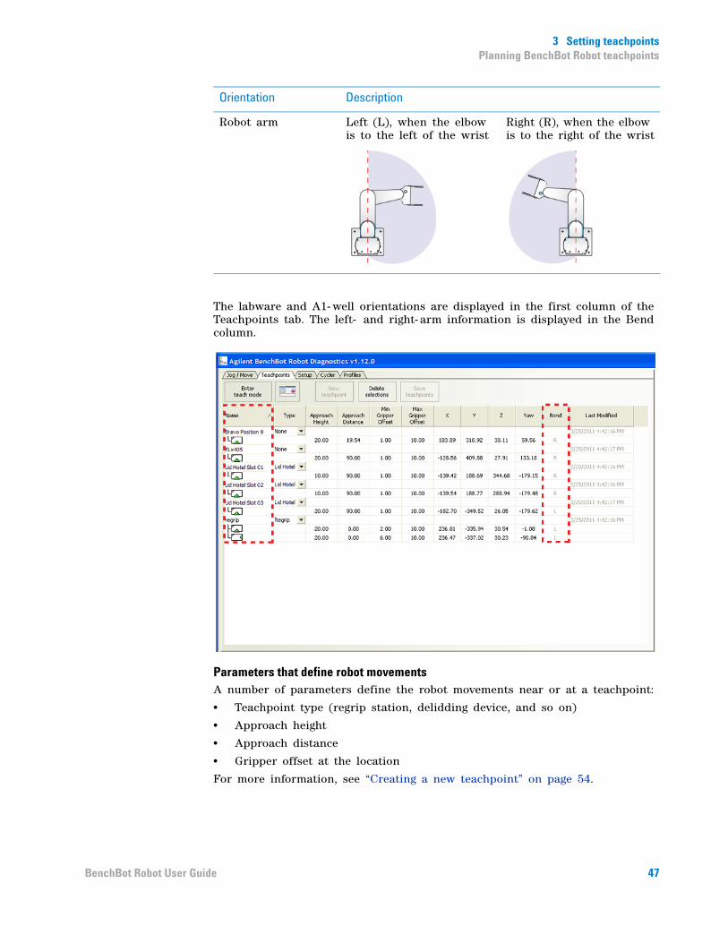
The labware and A1- well orientations are displayed in the first column of the Teachpoints tab. The left- and right- arm information is displayed in the Bend column.
Parameters that define robot movementsA number of parameters define the robot movements near or at a teachpoint:
• Teachpoint type (regrip station, delidding device, and so on)
• Approach height
• Approach distance
• Gripper offset at the location
For more information, see “Creating a new teachpoint” on page 54.
Robot arm Left (L), when the elbow is to the left of the wrist
Right (R), when the elbow is to the right of the wrist
Orientation Description
47BenchBot Robot User Guide
3 Setting teachpointsPlanning BenchBot Robot teachpoints
Guidelines for setting teachpoints
Before setting teachpoints, determine the best orientations for each location. In addition, be aware of how varying robot and labware orientations between teachpoints can affect robot speed and efficiency.
IMPORTANT The software will not permit you set teachpoints within the robot zone. Prompts will display to let you know that you are in the robot zone. For information about the robot zone, see “Retracting the robot into the robot zone” on page 106.
Orientations to considerBefore you set a teachpoint, take into consideration all of the following:
• Labware orientation. Determine the best labware orientation (landscape or portrait) for the location. The orientation might be determined by device requirements. For example, the Labware Stacker requires labware to be in the landscape orientation, but the MiniHub permits labware to be in either the landscape or portrait orientation.
• A1- well orientation. Determine the A1- well orientation of the labware. In general, for devices that require the landscape orientation, such as the Labware Stacker and the Centrifuge, the optimal A1- well orientation is typically away from the grippers. For storage devices that require the portrait orientation, the optimal A1- well orientation depends on the requirements at other teachpoints in the system. See “Examples” on page 49.
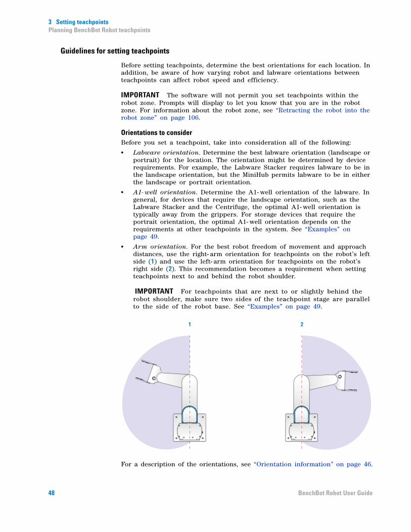
• Arm orientation. For the best robot freedom of movement and approach distances, use the right- arm orientation for teachpoints on the robot’s left side (1) and use the left- arm orientation for teachpoints on the robot’s right side (2). This recommendation becomes a requirement when setting teachpoints next to and behind the robot shoulder.
IMPORTANT For teachpoints that are next to or slightly behind the robot shoulder, make sure two sides of the teachpoint stage are parallel to the side of the robot base. See “Examples” on page 49.
For a description of the orientations, see “Orientation information” on page 46.
1 2
48 BenchBot Robot User Guide

3 Setting teachpointsPlanning BenchBot Robot teachpoints
Factors that affect robot speed and efficiencyTo increase robot speed and efficiency, you should:
• Add multiple orientations to a teachpoint. A regrip station is used if the robot needs to change the orientation of the labware it is holding as it transfers labware from one location to another. To reduce the number of regrips necessary, you can add multiple orientations to a teachpoint. For more information, see “Adding multiple orientations to a teachpoint” on page 68.
• Maximize the gripper offset ranges. A regrip station is used if the robot needs to adjust gripping height as it transfers a labware from one location that requires a gripper height that is different from the next location. To provide the system with the greatest flexibility for identifying a grip position that works for all locations, you should set the widest possible range for each gripper offset parameter. For more information about gripper offset ranges, see “Setting the Min and Max Gripper Offset parameters” on page 65.
• Set Approach Distance at the smallest possible value. In general, rotating robot movements are faster than linear movements. To ensure that the robot rotates from the robot zone directly to the teachpoint approach height, set the Approach Distance at 0. If obstacles near or at the teachpoint do not permit the rotating movement, set the Approach Distance at the smallest possible value for the location. For more information, see “Setting the Approach Height and Approach Distance parameters” on page 61.
Examples
Example 1: Robot-arm orientationIn the following example, the platepad (1) is on the left side of the robot. When setting the teachpoint at the platepad, use the right- arm orientation.
The Bravo Platform (2) is on the right side of the robot. When setting teachpoints at the Bravo Platform, use the left- arm orientation.
00240BravoPlate Orientation
1 2 3
4 5 67 8 9
00240
1
2
49BenchBot Robot User Guide
3 Setting teachpointsPlanning BenchBot Robot teachpoints
Example 2: A1-well orientation and the regrip station
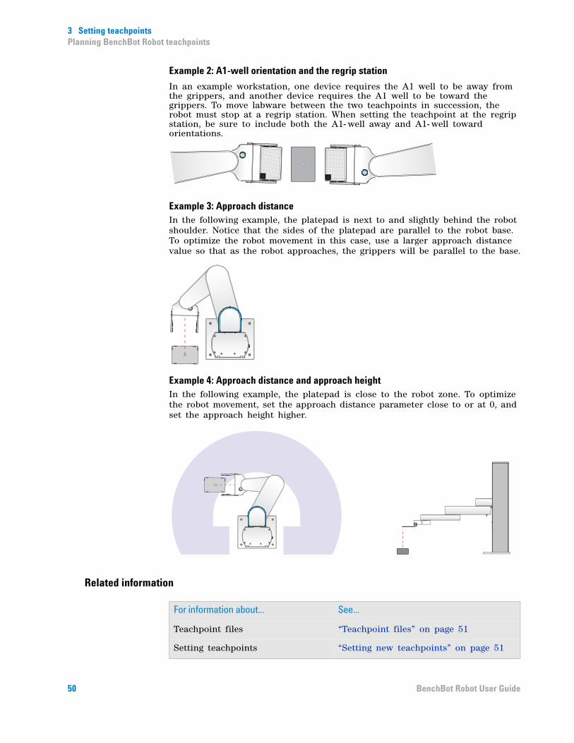
In an example workstation, one device requires the A1 well to be away from the grippers, and another device requires the A1 well to be toward the grippers. To move labware between the two teachpoints in succession, the robot must stop at a regrip station. When setting the teachpoint at the regrip station, be sure to include both the A1- well away and A1- well toward orientations.
Example 3: Approach distanceIn the following example, the platepad is next to and slightly behind the robot shoulder. Notice that the sides of the platepad are parallel to the robot base. To optimize the robot movement in this case, use a larger approach distance value so that as the robot approaches, the grippers will be parallel to the base.
Example 4: Approach distance and approach heightIn the following example, the platepad is close to the robot zone. To optimize the robot movement, set the approach distance parameter close to or at 0, and set the approach height higher.
Related information
A1A
1
For information about... See...
Teachpoint files “Teachpoint files” on page 51
Setting teachpoints “Setting new teachpoints” on page 51
50 BenchBot Robot User Guide

3 Setting teachpointsSetting new teachpoints
Setting new teachpoints
About this topic
Depending on the type of device, the teachpoint setting procedure can vary. This topic provides basic teachpoint setting concepts: how to use the supplied teaching plate or the desired labware to set, verify, and edit BenchBot Robot teachpoints.
Before you start
Make sure you have completed the following:
• Define labware.
• Set the BenchBot Robot properties in the VWorks Labware Editor.
For instructions, see the VWorks Automation Control Setup Guide.
Teachpoint files
The teachpoints you set are saved in the XML format in a teachpoint file. The default teachpoint file name is Teachpoints_<profilename>.xml, where <profilename> is the name of the profile. The software saves the file in the C:\VWorks Workspace\VWorks\BenchBot\Teachpoints folder. However, you can select another file name and location when saving the file.
You can have multiple teachpoint files for each BenchBot Robot if a device needs to serve multiple purposes. For example, a platepad can be taught as a platepad or as a regripping station. You can also have multiple teachpoint files for the system if a device is only used in some protocols but not others. For example, if a device is installed on a docking table and can be removed when it is not in use.
The teachpoint file is referenced by a profile. For information about profiles, see “Creating BenchBot Robot profiles” on page 29.
CAUTION Always edit and manage teachpoints in the Robot Diagnostics software. Do not edit the teachpoint file (XML file) directly. Editing the file directly can cause the robot to move to incorrect locations and bump into devices or other obstacles.
CAUTION Before you begin changing teachpoints, make a backup copy of the teachpoint file. If the original file becomes lost or damaged, you can use the backup copy instead of reteaching all the positions.
51BenchBot Robot User Guide
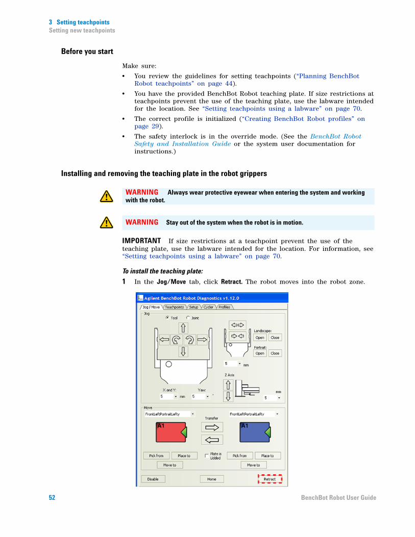
3 Setting teachpointsSetting new teachpoints
Before you start
Make sure:
• You review the guidelines for setting teachpoints (“Planning BenchBot Robot teachpoints” on page 44).
• You have the provided BenchBot Robot teaching plate. If size restrictions at teachpoints prevent the use of the teaching plate, use the labware intended for the location. See “Setting teachpoints using a labware” on page 70.
• The correct profile is initialized (“Creating BenchBot Robot profiles” on page 29).
• The safety interlock is in the override mode. (See the BenchBot Robot Safety and Installation Guide or the system user documentation for instructions.)
Installing and removing the teaching plate in the robot grippers
IMPORTANT If size restrictions at a teachpoint prevent the use of the teaching plate, use the labware intended for the location. For information, see “Setting teachpoints using a labware” on page 70.
To install the teaching plate:
1 In the Jog/Move tab, click Retract. The robot moves into the robot zone.
WARNING Always wear protective eyewear when entering the system and working with the robot.
WARNING Stay out of the system when the robot is in motion.
52 BenchBot Robot User Guide
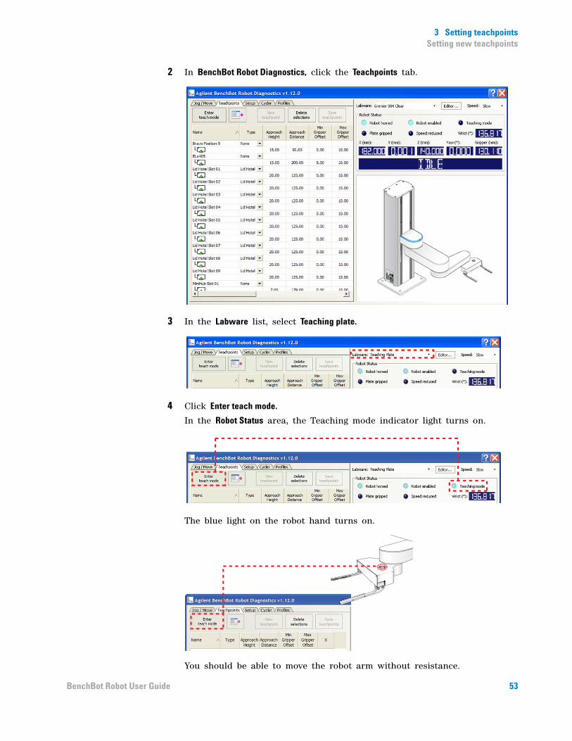
3 Setting teachpointsSetting new teachpoints
2 In BenchBot Robot Diagnostics, click the Teachpoints tab.
3 In the Labware list, select Teaching plate.
4 Click Enter teach mode.
In the Robot Status area, the Teaching mode indicator light turns on.
The blue light on the robot hand turns on.
You should be able to move the robot arm without resistance.
53BenchBot Robot User Guide
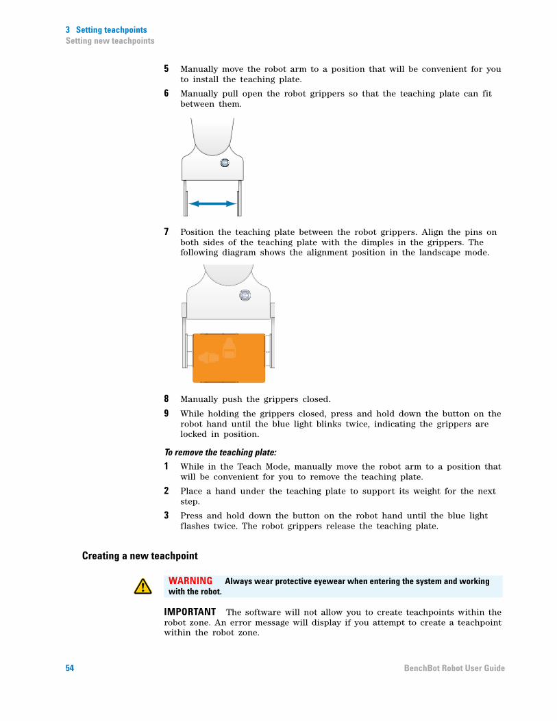
3 Setting teachpointsSetting new teachpoints
5 Manually move the robot arm to a position that will be convenient for you to install the teaching plate.
6 Manually pull open the robot grippers so that the teaching plate can fit between them.
7 Position the teaching plate between the robot grippers. Align the pins on both sides of the teaching plate with the dimples in the grippers. The following diagram shows the alignment position in the landscape mode.
8 Manually push the grippers closed.
9 While holding the grippers closed, press and hold down the button on the robot hand until the blue light blinks twice, indicating the grippers are locked in position.
To remove the teaching plate:
1 While in the Teach Mode, manually move the robot arm to a position that will be convenient for you to remove the teaching plate.
2 Place a hand under the teaching plate to support its weight for the next step.
3 Press and hold down the button on the robot hand until the blue light flashes twice. The robot grippers release the teaching plate.
Creating a new teachpoint
IMPORTANT The software will not allow you to create teachpoints within the robot zone. An error message will display if you attempt to create a teachpoint within the robot zone.
WARNING Always wear protective eyewear when entering the system and working with the robot.
54 BenchBot Robot User Guide
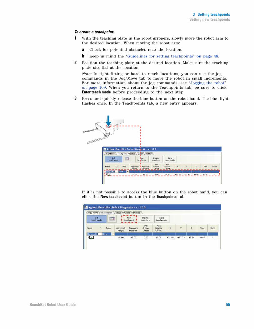
3 Setting teachpointsSetting new teachpoints
To create a teachpoint:
1 With the teaching plate in the robot grippers, slowly move the robot arm to the desired location. When moving the robot arm:
a Check for potential obstacles near the location.
b Keep in mind the “Guidelines for setting teachpoints” on page 48.
2 Position the teaching plate at the desired location. Make sure the teaching plate sits flat at the location.
Note: In tight- fitting or hard- to- reach locations, you can use the jog commands in the Jog/Move tab to move the robot in small increments. For more information about the jog commands, see “Jogging the robot” on page 109. When you return to the Teachpoints tab, be sure to click Enter teach mode before proceeding to the next step.
3 Press and quickly release the blue button on the robot hand. The blue light flashes once. In the Teachpoints tab, a new entry appears.
If it is not possible to access the blue button on the robot hand, you can click the New teachpoint button in the Teachpoints tab.
55BenchBot Robot User Guide
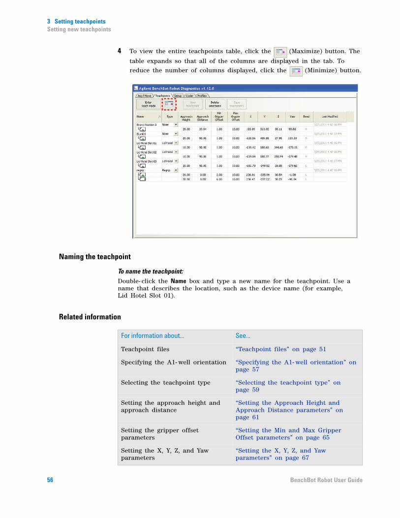
3 Setting teachpointsSetting new teachpoints
4 To view the entire teachpoints table, click the (Maximize) button. The
table expands so that all of the columns are displayed in the tab. To reduce the number of columns displayed, click the (Minimize) button.
Naming the teachpoint
To name the teachpoint:Double- click the Name box and type a new name for the teachpoint. Use a name that describes the location, such as the device name (for example, Lid Hotel Slot 01).
Related information
For information about... See...
Teachpoint files “Teachpoint files” on page 51
Specifying the A1- well orientation “Specifying the A1- well orientation” on page 57
Selecting the teachpoint type “Selecting the teachpoint type” on page 59
Setting the approach height and approach distance
“Setting the Approach Height and Approach Distance parameters” on page 61
Setting the gripper offset parameters
“Setting the Min and Max Gripper Offset parameters” on page 65
Setting the X, Y, Z, and Yaw parameters
“Setting the X, Y, Z, and Yaw parameters” on page 67
56 BenchBot Robot User Guide
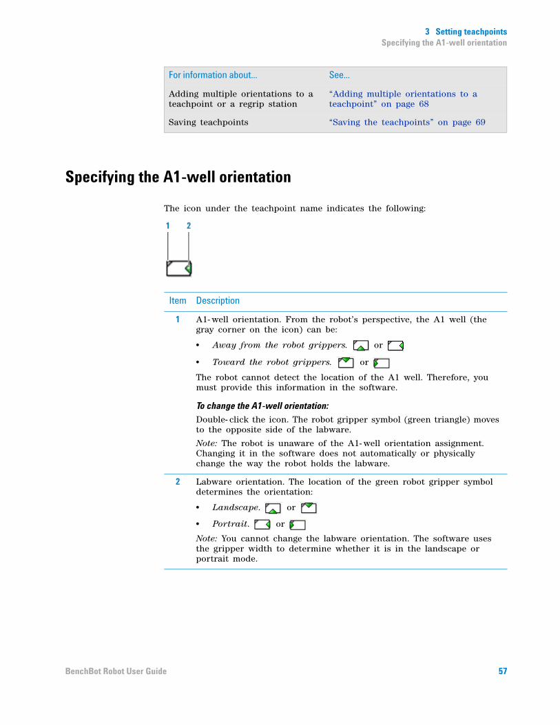
3 Setting teachpointsSpecifying the A1-well orientation
Specifying the A1-well orientation
The icon under the teachpoint name indicates the following:
Adding multiple orientations to a teachpoint or a regrip station
“Adding multiple orientations to a teachpoint” on page 68
Saving teachpoints “Saving the teachpoints” on page 69
For information about... See...
Item Description
1 A1- well orientation. From the robot’s perspective, the A1 well (the gray corner on the icon) can be:
• Away from the robot grippers. or
• Toward the robot grippers. or
The robot cannot detect the location of the A1 well. Therefore, you must provide this information in the software.
To change the A1-well orientation:
Double- click the icon. The robot gripper symbol (green triangle) moves to the opposite side of the labware.
Note: The robot is unaware of the A1- well orientation assignment. Changing it in the software does not automatically or physically change the way the robot holds the labware.
2 Labware orientation. The location of the green robot gripper symbol determines the orientation:
• Landscape. or
• Portrait. or
Note: You cannot change the labware orientation. The software uses the gripper width to determine whether it is in the landscape or portrait mode.
57BenchBot Robot User Guide

3 Setting teachpointsSpecifying the A1-well orientation
Possible orientationsFour orientations are possible for each teachpoint, based on different A1- well and labware orientations. The following table presents the four orientations.
Related information
Orientation icon Orientation description
Labware is in the landscape orientation. The A1 well is away from the grippers.
Labware is in the landscape orientation. The A1 well is toward the grippers.
Labware is in the portrait orientation. The A1 well is away from the grippers.
Labware is in the portrait orientation. The A1 well is toward the grippers.
For information about... See...
Setting teachpoints “Setting new teachpoints” on page 51
Selecting the teachpoint type “Selecting the teachpoint type” on page 59
Setting the approach height and approach distance
“Setting the Approach Height and Approach Distance parameters” on page 61
Setting the gripper offset parameters
“Setting the Min and Max Gripper Offset parameters” on page 65
Setting the X, Y, Z, and Yaw parameters
“Setting the X, Y, Z, and Yaw parameters” on page 67
58 BenchBot Robot User Guide
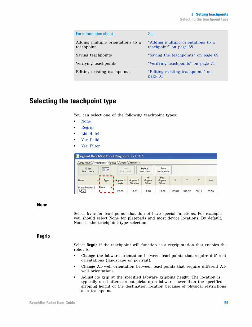
3 Setting teachpointsSelecting the teachpoint type
Selecting the teachpoint type
You can select one of the following teachpoint types:
• None
• Regrip
• Lid Hotel
• Vac Delid
• Vac Filter
None
Select None for teachpoints that do not have special functions. For example, you should select None for platepads and most device locations. By default, None is the teachpoint type selection.
Regrip
Select Regrip if the teachpoint will function as a regrip station that enables the robot to:
• Change the labware orientation between teachpoints that require different orientations (landscape or portrait).
• Change A1- well orientation between teachpoints that require different A1-well orientations.
• Adjust its grip at the specified labware gripping height. The location is typically used after a robot picks up a labware lower than the specified gripping height of the destination location because of physical restrictions at a teachpoint.
Adding multiple orientations to a teachpoint
“Adding multiple orientations to a teachpoint” on page 68
Saving teachpoints “Saving the teachpoints” on page 69
Verifying teachpoints “Verifying teachpoints” on page 71
Editing existing teachpoints “Editing existing teachpoints” on page 81
For information about... See...
59BenchBot Robot User Guide

3 Setting teachpointsSelecting the teachpoint type
IMPORTANT The regrip station is only known to the robot and is not a device in the device file. Do not add the regrip station as a platepad device in the device file and use it for other purposes such as deadlock avoidance.
To accommodate different labware orientations, add multiple orientations to the regrip teachpoint. For instructions, see “Adding multiple orientations to a teachpoint” on page 68.
Lid Hotel
Select Lid Hotel for teachpoints in the Lid Hotel Station. The selection tells the software that delidding and relidding actions will take place at the hotel.
Vac Delid
Select Vac Delid for the teachpoint at the Vacuum Delid Station. The selection tells the software that tipbox- delidding actions will take place at the station.
Vac Filter
Select Vac Filter to press down labware at the teachpoint. For example, you can use this teachpoint type to press down PCR microplates or microplates that will sit on vacuum filtration stations.
Related information
For information about... See...
Setting teachpoints “Setting new teachpoints” on page 51 and the relevant device guide
Specifying the A1- well orientation “Specifying the A1- well orientation” on page 57
Setting the approach height and approach distance
“Setting the Approach Height and Approach Distance parameters” on page 61
Setting the gripper offset parameters
“Setting the Min and Max Gripper Offset parameters” on page 65
Setting the X, Y, Z, and Yaw parameters
“Setting the X, Y, Z, and Yaw parameters” on page 67
Adding multiple orientations to a regrip station or a teachpoint
“Adding multiple orientations to a teachpoint” on page 68
Saving teachpoints “Saving the teachpoints” on page 69
Verifying teachpoints “Verifying teachpoints” on page 71
Editing existing teachpoints “Editing existing teachpoints” on page 81
60 BenchBot Robot User Guide

3 Setting teachpointsSetting the Approach Height and Approach Distance parameters
Setting the Approach Height and Approach Distance parameters
About this topic
The Approach Height and Approach Distance parameters are used together to clear obstacles near or at a teachpoint. This topic explains the function of each parameter and provides guidance for setting values that work optimally together.
Approach Height
Approach Height is the height clearance, in millimeters, the robot must maintain above the teachpoint as it moves towards or away from the teachpoint with labware in its grippers.
You can reduce the Approach Height value to prevent collision with shelves or other obstacles above the teachpoint. However, make sure there is sufficient clearance below the labware to prevent collision with raised tabs or other obstacles at the teachpoint.
Note: To prevent collisions, the software does not allow you to set an Approach Height value that is less than the minimum gripper offset value.
Approach Distance
Approach Distance is the straight- line distance, in millimeters, from the teachpoint. Within this distance, the robot must:
• Maintain the specified approach height for the teachpoint.
• Move in a straight line toward or away from the teachpoint.
Approach Height
CAUTION Incorrect approach heights can cause the robot to crash into obstacles.
61BenchBot Robot User Guide

3 Setting teachpointsSetting the Approach Height and Approach Distance parameters
You use Approach Distance to ensure that the robot maintains a straight path while approaching or moving away from the teachpoint. Doing so enables the robot to navigate in tight spaces while avoiding obstacles.
For example, you can use the Approach Distance parameter to make sure the robot grippers can enter and exit a device such as the Microplate Centrifuge without bumping into the sides of the narrow entryway.
Guidelines for setting the parameters
IMPORTANT The Approach Height value works in conjunction with the Approach Distance to clear obstacles near or at the teachpoint. Therefore, before setting the approach height value, you should determine the approach distance value to use.
In general, use the following guidelines when specifying values for these parameters:
• For most devices, you can set Approach Height at 9 mm.
• If Approach Distance is set at the default value, the Approach Height value should allow the robot and labware to arrive at the teachpoint without bumping into any obstacles, such as raised tabs, at the front of the teachpoint.
• If Approach Distance is less than the default value, the Approach Height value should allow the robot and labware to arrive at the teachpoint without bumping into any obstacles, such as raised tabs, at the front and sides of the teachpoint.
• Rotating robot movements are faster than linear movements. If Approach Distance is set at 0 mm, the robot will move (or mostly rotate) from the robot zone directly to the teachpoint at the Approach Height.
Before setting Approach Distance at 0 mm, you should consider the obstacles surrounding and at the teachpoint. If obstacles near or at the teachpoint do not permit the rotating movement, set Approach Distance at the smallest possible value for the location.
• If Approach Distance is 0 mm, Approach Height must be a higher value to ensure clearance for the tallest labware that will be placed at the teachpoint.
• If Approach Distance is greater than 60 mm (landscape orientation) or 85 mm (portrait orientation), Approach Height needs to be high enough to clear raised tabs at the teachpoint.
IMPORTANT The software will not allow you to specify an Approach Height or Approach Distance value that is too large for the teachpoint.
62 BenchBot Robot User Guide

3 Setting teachpointsSetting the Approach Height and Approach Distance parameters
The following table summarizes the guidelines for setting the Approach Height and Approach Distance parameters.
Examples
Example 1: High Approach Height, low Approach DistanceIn the following diagram, the teachpoint (1) does not have obstacles nearby. In this case, set the Approach Distance at 0 mm to take advantage of the robot’s rotating movement. Because the tallest labware expected at the teachpoint is a tipbox, the Approach Height is set at 70 mm.
Approach Distance
(low value)
Approach Distance
(high value)
Approach Height
(low value)
Atypical
• Obstacles above the teachpoint
• Teachpoint close to the robot zone
Typical
• Obstacle on sides of the teachpoint
• Obstacles above the teachpoint
• Low tabs on the front of the teachpoint
See Example 2: Low Approach Height, high Approach Distance.
Approach Height
(high value)
Typical
• No obstacles on sides of the teachpoint
• No obstacles above the teachpoint
See Example 1: High Approach Height, low Approach Distance.
Atypical
• Tall obstacle on sides of the teachpoint
• No obstacles above the teachpoint
• High tabs on the front of the teachpoint
0 mm
70 mm
1
1
63BenchBot Robot User Guide

3 Setting teachpointsSetting the Approach Height and Approach Distance parameters
Example 2: Low Approach Height, high Approach DistanceIn the following diagram, the teachpoint (1) has two tall obstacles on both sides. In this case, set the Approach Distance at 200 mm (the distance that allows the robot to move to the teachpoint without bumping into the tall obstacles). The Approach Height is set at 9 mm to avoid the tabs on the front side of the teachpoint.
Procedure
To set the Approach Height parameter:
Double- click in the Approach Height box and type the desired value. The default value for the parameter is 20 mm.
To set the Approach Distance parameter:Double- click in the Approach Distance box and type the desired value. The default value is 75 mm for the landscape orientation and 125 mm for the portrait orientation.
Related information
200 mm
9 mm
1
1
For information about... See...
Specifying the A1- well orientation “Specifying the A1- well orientation” on page 57
Selecting the teachpoint type “Selecting the teachpoint type” on page 59
Setting the gripper offset parameters
“Setting the Min and Max Gripper Offset parameters” on page 65
Setting the X, Y, Z, and Yaw parameters
“Setting the X, Y, Z, and Yaw parameters” on page 67
Adding multiple orientations to a regrip station or a teachpoint
“Adding multiple orientations to a teachpoint” on page 68
Saving teachpoints “Saving the teachpoints” on page 69
Verifying teachpoints “Verifying teachpoints” on page 71
64 BenchBot Robot User Guide
3 Setting teachpointsSetting the Min and Max Gripper Offset parameters
Setting the Min and Max Gripper Offset parameters
About the Min and Max Gripper Offset parametersThe labware gripping offset range (Min and Max) parameters tell the BenchBot Robot where to grip a given labware type when transferring it from one device to another. Each device within a system can pose different accessibility challenges when transferring the labware. For example, some devices can have a deep, recessed area, whereas others are more flat. Some devices might have tall flanges that make it impossible for the robot to grip a microplate at a very low point.
You can set two types of gripper offset ranges:
• Gripper offset range for the labware. Specified on the BenchBot Robot tab in the Labware Editor for each labware definition.
• Gripper offset range for the device. Specified in the BenchBot Robot Diagnostics software for a given device.
During a protocol run, the BenchBot Robot uses three gripper offset ranges to determine the most compatible grip position for the labware:
• Gripper offset range for the labware
• Gripper offset range for the device (A) where it will pick up the labware
• Gripper offset range for the device (B) where it will place the labware
You should set the widest possible range for each gripper offset parameter. If the three gripper offset ranges overlap, the robot will use the smallest common gripper offset to perform a direct labware transfer from device A to device B without regripping the labware. If the three ranges do not overlap, the software attempts to plan a path through one or more regrip stations. If the robot cannot perform the transfer, an error message appears at the time of the requested labware transfer.
To provide the system with the greatest flexibility for identifying a grip position that works for all locations, you should set the widest possible range for each gripper offset parameter.
Note: To catch and correct potential labware transfer errors, Agilent Technologies recommends that you verify the teachpoints and perform a dry run.
Before you set the gripper offset parametersUnder some circumstances, you should consider the gripper offset ranges of more than two teachpoints to avoid a regrip. For example, a labware will be delidded as it moves from the pick location (device A) to the place location (device B). In this case, the gripper offset range for the delid teachpoint must also overlap with the gripper offset range for the labware, device A, and device B.
65BenchBot Robot User Guide

3 Setting teachpointsSetting the Min and Max Gripper Offset parameters
Procedure
To set the Min Gripper Offset and the Max Gripper Offset parameters for a device:Double- click the Min Gripper Offset and Max Gripper Offset box and type the desired values:
• Min Gripper Offset. The vertical distance (mm) from the bottom of the labware that is sitting at the teachpoint to the lowest point where the robot grippers can hold the microplate securely. The default value is 0 mm.
• Max Gripper Offset. The vertical distance (mm) from the bottom of the labware that is sitting at the teachpoint to the highest point where the robot grippers can hold the microplate securely. The default value is 20 mm.
IMPORTANT For regrip stations, make sure the gripper offset range can accommodate all types of labware.
Related information
MaximumMinimum
For information about... See...
Setting teachpoints “Setting new teachpoints” on page 51
Specifying the A1- well orientation “Specifying the A1- well orientation” on page 57
Selecting the teachpoint type “Selecting the teachpoint type” on page 59
Setting the approach height and approach distance
“Setting the Approach Height and Approach Distance parameters” on page 61
Adding multiple orientations to a teachpoint
“Adding multiple orientations to a teachpoint” on page 68
Setting the X, Y, Z, and Yaw parameters
“Setting the X, Y, Z, and Yaw parameters” on page 67
Saving teachpoints “Saving the teachpoints” on page 69
Verifying teachpoints “Verifying teachpoints” on page 71
Editing existing teachpoints “Editing existing teachpoints” on page 81
66 BenchBot Robot User Guide
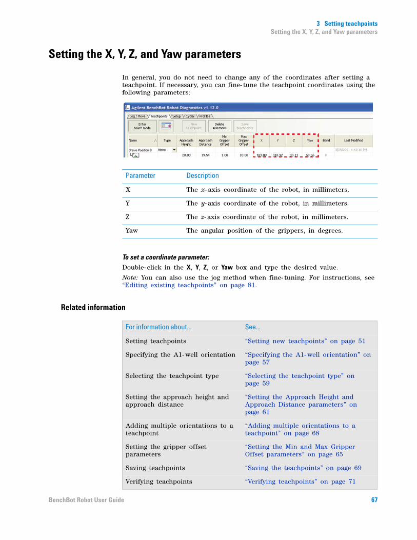
3 Setting teachpointsSetting the X, Y, Z, and Yaw parameters
Setting the X, Y, Z, and Yaw parameters
In general, you do not need to change any of the coordinates after setting a teachpoint. If necessary, you can fine- tune the teachpoint coordinates using the following parameters:
To set a coordinate parameter:
Double- click in the X, Y, Z, or Yaw box and type the desired value.
Note: You can also use the jog method when fine- tuning. For instructions, see “Editing existing teachpoints” on page 81.
Related information
Parameter Description
X The x- axis coordinate of the robot, in millimeters.
Y The y- axis coordinate of the robot, in millimeters.
Z The z- axis coordinate of the robot, in millimeters.
Yaw The angular position of the grippers, in degrees.
For information about... See...
Setting teachpoints “Setting new teachpoints” on page 51
Specifying the A1- well orientation “Specifying the A1- well orientation” on page 57
Selecting the teachpoint type “Selecting the teachpoint type” on page 59
Setting the approach height and approach distance
“Setting the Approach Height and Approach Distance parameters” on page 61
Adding multiple orientations to a teachpoint
“Adding multiple orientations to a teachpoint” on page 68
Setting the gripper offset parameters
“Setting the Min and Max Gripper Offset parameters” on page 65
Saving teachpoints “Saving the teachpoints” on page 69
Verifying teachpoints “Verifying teachpoints” on page 71
67BenchBot Robot User Guide

3 Setting teachpointsAdding multiple orientations to a teachpoint
Adding multiple orientations to a teachpoint
Procedure
You can add multiple orientations to a regrip station. You can also add multiple orientations to a teachpoint to reduce the number of regrips necessary during a protocol run. For example, if a teachpoint has both the landscape and portrait orientations, a regrip will not be required when transferring labware to and from this teachpoint.
To add additional orientations to a regrip station or a teachpoint:
1 Create another teachpoint at the same location but with a different orientation. A new entry appears in the teachpoints table.
2 If necessary, set the A1- well orientation. By default, a new teachpoint will always have the A1- away orientation. Drag the new teachpoint under an existing teachpoint.
3 Set the remaining teachpoint parameters.
Related information
CAUTION The new teachpoint must have a different orientation than the existing teachpoint. Otherwise, the software will prompt you to replace or reteach the existing teachpoint during the drag-and-drop operation.
For information about... See...
Setting teachpoints “Setting new teachpoints” on page 51
Specifying the A1- well orientation “Specifying the A1- well orientation” on page 57
Selecting the teachpoint type “Selecting the teachpoint type” on page 59
Setting the approach height and approach distance
“Setting the Approach Height and Approach Distance parameters” on page 61
Setting the gripper offset parameters
“Setting the Min and Max Gripper Offset parameters” on page 65
Setting the X, Y, Z, and Yaw parameters
“Setting the X, Y, Z, and Yaw parameters” on page 67
Verifying teachpoints “Verifying teachpoints” on page 71
Editing existing teachpoints “Editing existing teachpoints” on page 81
68 BenchBot Robot User Guide

3 Setting teachpointsSaving the teachpoints
Saving the teachpoints
To save the teachpoints, click Save teachpoints.
Be sure to remove the teaching plate from the robot grippers when you are finished. See “Installing and removing the teaching plate in the robot grippers” on page 52.
Related information
For information about... See...
Setting teachpoints “Setting new teachpoints” on page 51
Specifying the A1- well orientation “Specifying the A1- well orientation” on page 57
Selecting the teachpoint type “Selecting the teachpoint type” on page 59
Setting the approach height and approach distance
“Setting the Approach Height and Approach Distance parameters” on page 61
Adding multiple orientations to a teachpoint
“Adding multiple orientations to a teachpoint” on page 68
Setting the gripper offset parameters
“Setting the Min and Max Gripper Offset parameters” on page 65
Setting the X, Y, Z, and Yaw parameters
“Setting the X, Y, Z, and Yaw parameters” on page 67
Adding multiple orientations to a teachpoint or a regrip station
“Adding multiple orientations to a teachpoint” on page 68
Verifying teachpoints “Verifying teachpoints” on page 71
Editing existing teachpoints “Editing existing teachpoints” on page 81
69BenchBot Robot User Guide
3 Setting teachpointsSetting teachpoints using a labware
Setting teachpoints using a labware
When to use labware instead of the teaching plate
In cases where size restriction at a teachpoint prevents the use of the teaching plate, you can use the labware intended for the location.
Procedure
To use a labware in the teaching procedure:
1 Teach a reference location, such as Platepad 1, using the teaching plate. Follow the instructions in “Setting new teachpoints” on page 51.
IMPORTANT When teaching the reference location, make sure the Min gripper offset parameter value is less than or equal to the minimum gripper offset value specified for the labware in the Labware Editor.
2 Verify the Platepad 1 teachpoint. Follow the instructions in “Verifying teachpoints” on page 71.
3 Place the desired labware at Platepad 1.
4 Follow the instructions in “Picking up labware at the teachpoint” on page 74 to pick up the labware from Platepad 1.
5 In BenchBot Diagnostics, click Teach Mode. The blue light on the robot hand turns on to indicate that it is in the teach mode. You should be able to move the robot arm without resistance.
6 Follow the instructions in “Creating a new teachpoint” on page 54 to create a new teachpoint.
7 Set the teachpoint parameters.
8 Save the teachpoint.
9 Verify and edit the teachpoint.
Related information
WARNING Always wear protective eyewear when entering the system and working with the robot.
CAUTION When using a labware to set teachpoints, the software assumes that the robot is holding the labware at the minimum gripper offset.
For information about... See...
Workflow for setting teachpoints “Teachpoint setting workflow” on page 42
Verifying teachpoints “Verifying teachpoints” on page 71
Cycling teachpoints “Cycling teachpoints” on page 87
70 BenchBot Robot User Guide

3 Setting teachpointsVerifying teachpoints
Verifying teachpoints
After you set a new teachpoint, you should verify that it is accurate by:
• Moving the robot to the new teachpoint
• Picking up labware at the teachpoint
• Placing labware at the teachpoint
• Transferring labware between two teachpoints
You use the commands in the Jog/Move tab for the verification procedure.
Moving the robot to the new teachpoint
You use the Move to command to check that:
• The robot is able to move to the selected teachpoint.
• The approach orientation at the teachpoint is correct.
WARNING To prevent puncture or other injuries to the eyes, be sure to wear protective eyewear when entering the system and working with the robot.
WARNING Stay out of the system while the robot is in motion. Entering the system while the robot or other devices are in motion can cause personal injury.
71BenchBot Robot User Guide

3 Setting teachpointsVerifying teachpoints
To move the robot to the teachpoint:
1 Make sure the robot has a clear path to the teachpoint. Remove any obstacles in the path. If the robot arm is extended, move the arm into the robot zone.
2 In BenchBot Robot Diagnostics, make sure the correct labware is selected in the Labware list.
3 In the Speed list, select Slow.
4 Click the Jog/Move tab, and, if necessary, click Enable to enable the robot motors.
5 In the Move area, select the teachpoint you want to verify from the list above the red labware.
In the following example, the Platepad01 teachpoint is selected.
72 BenchBot Robot User Guide
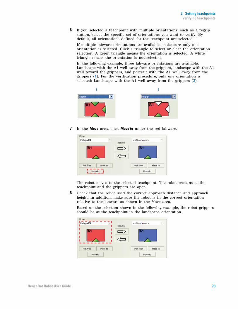
3 Setting teachpointsVerifying teachpoints
6 If you selected a teachpoint with multiple orientations, such as a regrip station, select the specific set of orientations you want to verify. By default, all orientations defined for the teachpoint are selected.
If multiple labware orientations are available, make sure only one orientation is selected. Click a triangle to select or clear the orientation selection. A green triangle means the orientation is selected. A white triangle means the orientation is not selected.
In the following example, three labware orientations are available: Landscape with the A1 well away from the grippers, landscape with the A1 well toward the grippers, and portrait with the A1 well away from the grippers (1). For the verification procedure, only one orientation is selected: Landscape with the A1 well away from the grippers (2).
7 In the Move area, click Move to under the red labware.
The robot moves to the selected teachpoint. The robot remains at the teachpoint and the grippers are open.
8 Check that the robot used the correct approach distance and approach height. In addition, make sure the robot is in the correct orientation relative to the labware as shown in the Move area.
Based on the selection shown in the following example, the robot grippers should be at the teachpoint in the landscape orientation.
73BenchBot Robot User Guide

3 Setting teachpointsVerifying teachpoints
9 To make adjustments, proceed to “Editing existing teachpoints” on page 81.
10 Repeat the procedure for another teachpoint. If you are verifying a teachpoint with multiple orientations, be sure to verify each orientation before checking another teachpoint.
Picking up labware at the teachpoint
You use the Pick from command to check that:
• The robot is using the correct approach distance and approach height as it moves to and from the teachpoint.
• The robot is able to pick up labware at the selected teachpoint.
• The robot picks up the labware within the specified gripper offset range.
To pick up labware from the teachpoint:
1 Make sure the robot has a clear path to the teachpoint. Remove any obstacles in the path. If the robot arm is extended, move the arm into the robot zone.
2 Manually place the labware at the teachpoint.
3 In BenchBot Diagnostics, select the labware you want to use from the Labware list.
4 In the Speed list, select Slow.
5 Labware with lids only. In the Move area, select Plate is Lidded to indicate the robot will be moving a labware that has a lid. This selection is only available if you selected a labware that can have lids. (If you selected a labware that cannot have lids, the Plate is Lidded selection is not visible.) If the labware can have lids but you intend to move it without the lid, clear the check box.
WARNING Be sure to wear protective eyewear when entering the system and working with the robot.
WARNING Stay out of the system while the robot is in motion.
74 BenchBot Robot User Guide
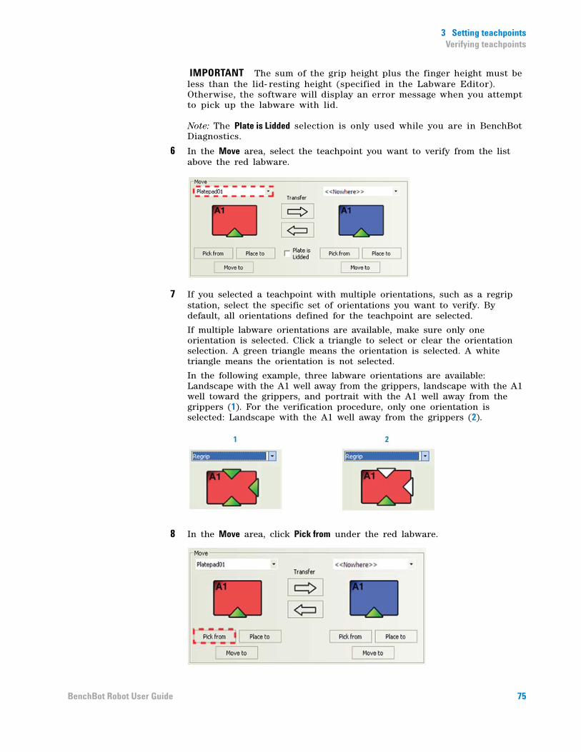
3 Setting teachpointsVerifying teachpoints
IMPORTANT The sum of the grip height plus the finger height must be less than the lid- resting height (specified in the Labware Editor). Otherwise, the software will display an error message when you attempt to pick up the labware with lid.
Note: The Plate is Lidded selection is only used while you are in BenchBot Diagnostics.
6 In the Move area, select the teachpoint you want to verify from the list above the red labware.
7 If you selected a teachpoint with multiple orientations, such as a regrip station, select the specific set of orientations you want to verify. By default, all orientations defined for the teachpoint are selected.
If multiple labware orientations are available, make sure only one orientation is selected. Click a triangle to select or clear the orientation selection. A green triangle means the orientation is selected. A white triangle means the orientation is not selected.
In the following example, three labware orientations are available: Landscape with the A1 well away from the grippers, landscape with the A1 well toward the grippers, and portrait with the A1 well away from the grippers (1). For the verification procedure, only one orientation is selected: Landscape with the A1 well away from the grippers (2).
8 In the Move area, click Pick from under the red labware.
75BenchBot Robot User Guide

3 Setting teachpointsVerifying teachpoints
The robot moves to the teachpoint, picks up the labware, and moves it to the robot zone. The labware remains in the robot grippers.
9 Check that the robot used the correct approach distance and approach height when picking up the labware. Also check that the robot is holding the labware within the specified gripper offset range.
10 To make adjustments, proceed to “Editing existing teachpoints” on page 81.
11 If the robot has completed its task correctly, remove the labware from the robot grippers and repeat the procedure for another teachpoint. If you are verifying a teachpoint with multiple orientations, be sure to verify each orientation before checking another teachpoint.
Placing labware at the teachpoint
You use the Place to command to check that:
• The robot is using the correct approach distance and approach height as it moves to and from the teachpoint.
• The robot is able to place the selected labware at the selected teachpoint.
IMPORTANT To use the Place to command, you must first use the Pick from command to pick up a labware so that the gripper offset is known.
To place labware at the teachpoint:
1 Make sure the robot has a clear path to the teachpoint. Remove any obstacles in the path. If the robot arm is extended, move the arm into the robot zone.
2 Make sure the robot is still holding the labware from the previous procedure (“Picking up labware at the teachpoint” on page 74).
3 In BenchBot Diagnostics, make sure the correct labware is selected in the Labware list.
4 In the Speed list, select Slow.
5 Labware with lids only. In the Move area, select Plate is Lidded to indicate the robot will be moving a labware that has a lid. This selection is only available if you selected a labware that can have lids. (If you selected a labware that cannot have lids, the Plate is Lidded selection is not visible.) If the labware can have lids but you intend to move it without the lid, clear the check box.
WARNING Be sure to wear protective eyewear when entering the system and working with the robot.
WARNING Stay out of the system while the robot is in motion.
76 BenchBot Robot User Guide
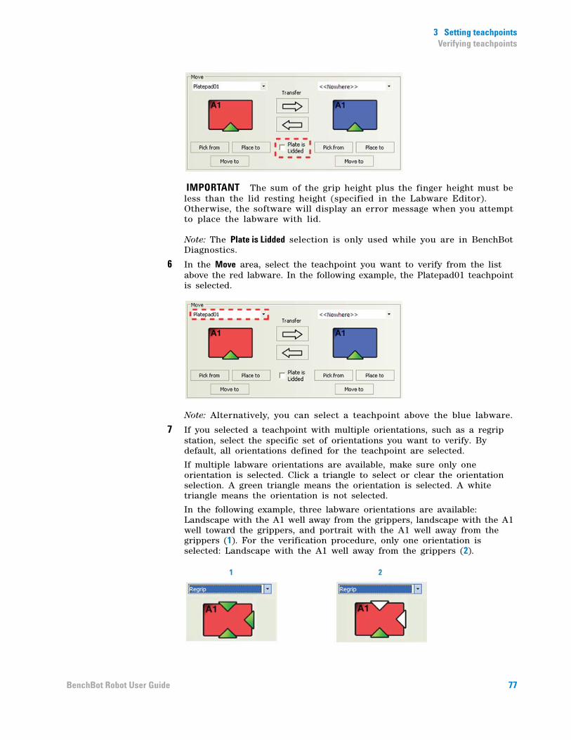
3 Setting teachpointsVerifying teachpoints
IMPORTANT The sum of the grip height plus the finger height must be less than the lid resting height (specified in the Labware Editor). Otherwise, the software will display an error message when you attempt to place the labware with lid.
Note: The Plate is Lidded selection is only used while you are in BenchBot Diagnostics.
6 In the Move area, select the teachpoint you want to verify from the list above the red labware. In the following example, the Platepad01 teachpoint is selected.
Note: Alternatively, you can select a teachpoint above the blue labware.
7 If you selected a teachpoint with multiple orientations, such as a regrip station, select the specific set of orientations you want to verify. By default, all orientations defined for the teachpoint are selected.
If multiple labware orientations are available, make sure only one orientation is selected. Click a triangle to select or clear the orientation selection. A green triangle means the orientation is selected. A white triangle means the orientation is not selected.
In the following example, three labware orientations are available: Landscape with the A1 well away from the grippers, landscape with the A1 well toward the grippers, and portrait with the A1 well away from the grippers (1). For the verification procedure, only one orientation is selected: Landscape with the A1 well away from the grippers (2).
77BenchBot Robot User Guide
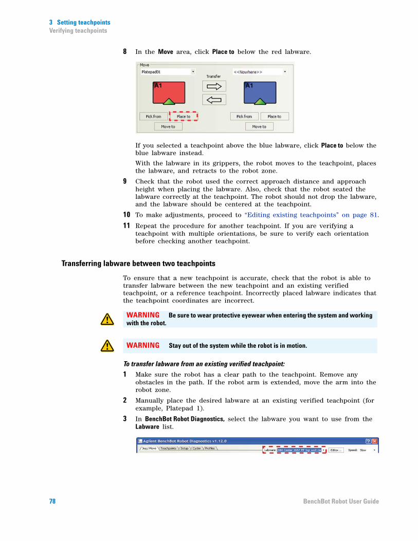
3 Setting teachpointsVerifying teachpoints
8 In the Move area, click Place to below the red labware.
If you selected a teachpoint above the blue labware, click Place to below the blue labware instead.
With the labware in its grippers, the robot moves to the teachpoint, places the labware, and retracts to the robot zone.
9 Check that the robot used the correct approach distance and approach height when placing the labware. Also, check that the robot seated the labware correctly at the teachpoint. The robot should not drop the labware, and the labware should be centered at the teachpoint.
10 To make adjustments, proceed to “Editing existing teachpoints” on page 81.
11 Repeat the procedure for another teachpoint. If you are verifying a teachpoint with multiple orientations, be sure to verify each orientation before checking another teachpoint.
Transferring labware between two teachpoints
To ensure that a new teachpoint is accurate, check that the robot is able to transfer labware between the new teachpoint and an existing verified teachpoint, or a reference teachpoint. Incorrectly placed labware indicates that the teachpoint coordinates are incorrect.
To transfer labware from an existing verified teachpoint:
1 Make sure the robot has a clear path to the teachpoint. Remove any obstacles in the path. If the robot arm is extended, move the arm into the robot zone.
2 Manually place the desired labware at an existing verified teachpoint (for example, Platepad 1).
3 In BenchBot Robot Diagnostics, select the labware you want to use from the Labware list.
WARNING Be sure to wear protective eyewear when entering the system and working with the robot.
WARNING Stay out of the system while the robot is in motion.
78 BenchBot Robot User Guide
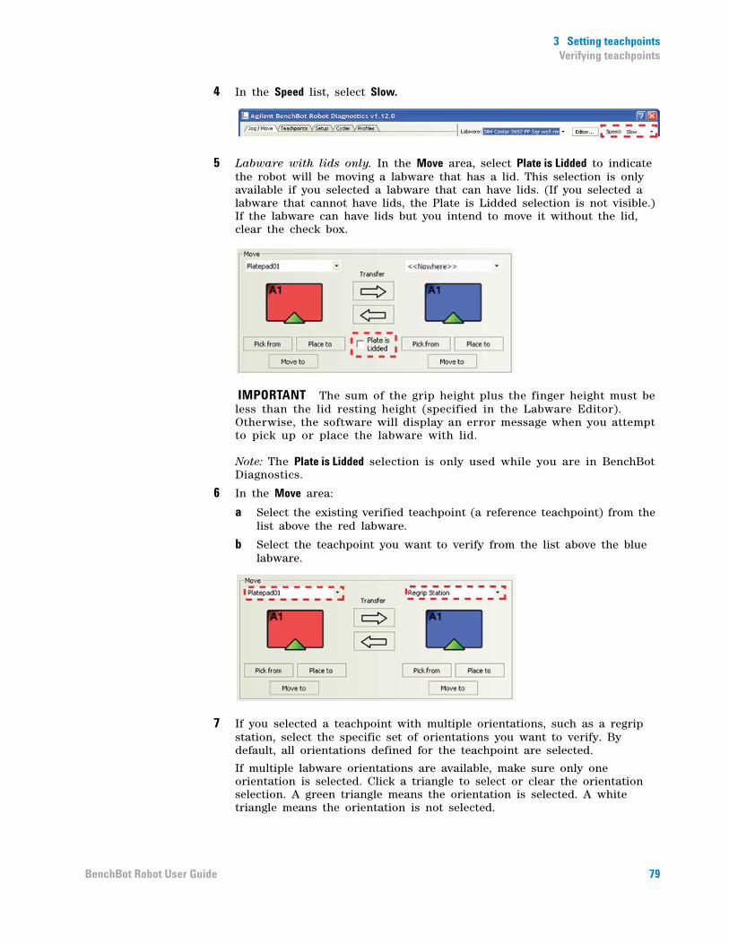
3 Setting teachpointsVerifying teachpoints
4 In the Speed list, select Slow.
5 Labware with lids only. In the Move area, select Plate is Lidded to indicate the robot will be moving a labware that has a lid. This selection is only available if you selected a labware that can have lids. (If you selected a labware that cannot have lids, the Plate is Lidded selection is not visible.) If the labware can have lids but you intend to move it without the lid, clear the check box.
IMPORTANT The sum of the grip height plus the finger height must be less than the lid resting height (specified in the Labware Editor). Otherwise, the software will display an error message when you attempt to pick up or place the labware with lid.
Note: The Plate is Lidded selection is only used while you are in BenchBot Diagnostics.
6 In the Move area:
a Select the existing verified teachpoint (a reference teachpoint) from the list above the red labware.
b Select the teachpoint you want to verify from the list above the blue labware.
7 If you selected a teachpoint with multiple orientations, such as a regrip station, select the specific set of orientations you want to verify. By default, all orientations defined for the teachpoint are selected.
If multiple labware orientations are available, make sure only one orientation is selected. Click a triangle to select or clear the orientation selection. A green triangle means the orientation is selected. A white triangle means the orientation is not selected.
79BenchBot Robot User Guide
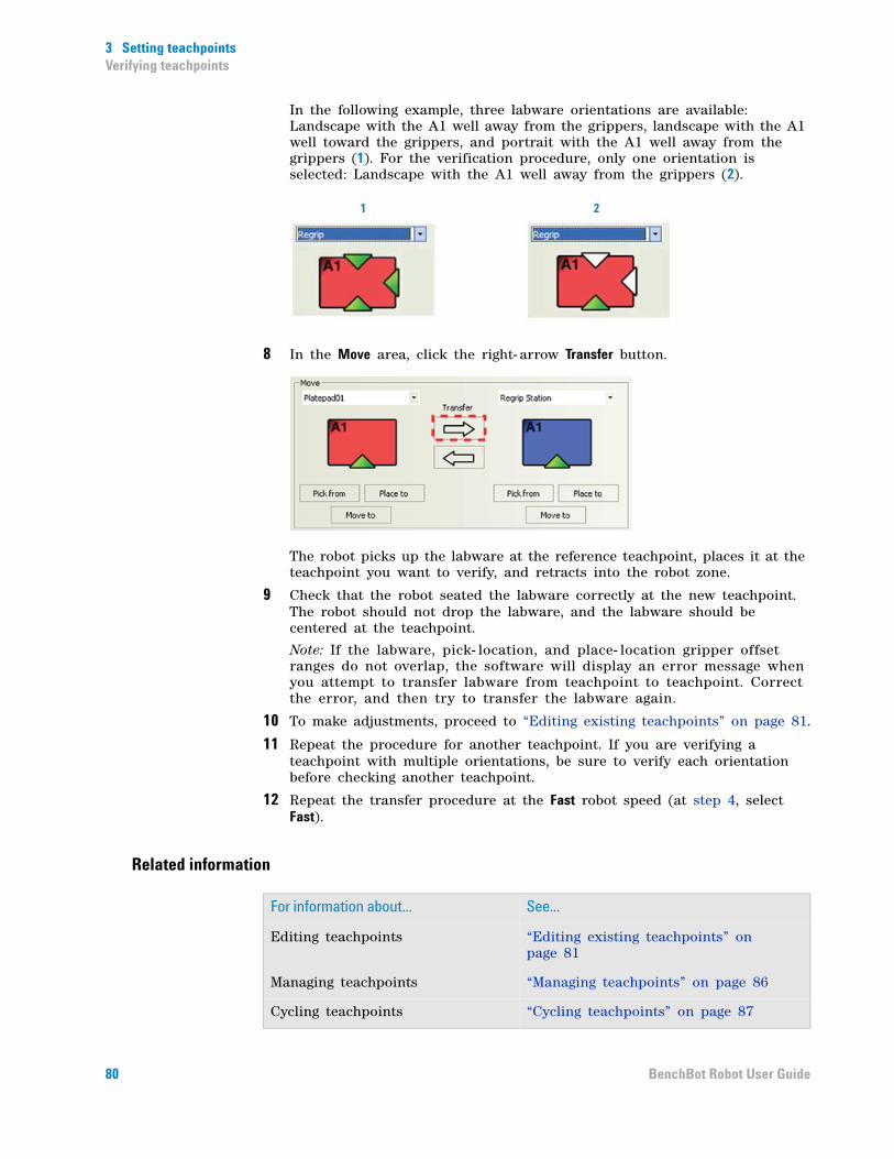
3 Setting teachpointsVerifying teachpoints
In the following example, three labware orientations are available: Landscape with the A1 well away from the grippers, landscape with the A1 well toward the grippers, and portrait with the A1 well away from the grippers (1). For the verification procedure, only one orientation is selected: Landscape with the A1 well away from the grippers (2).
8 In the Move area, click the right- arrow Transfer button.
The robot picks up the labware at the reference teachpoint, places it at the teachpoint you want to verify, and retracts into the robot zone.
9 Check that the robot seated the labware correctly at the new teachpoint. The robot should not drop the labware, and the labware should be centered at the teachpoint.
Note: If the labware, pick- location, and place- location gripper offset ranges do not overlap, the software will display an error message when you attempt to transfer labware from teachpoint to teachpoint. Correct the error, and then try to transfer the labware again.
10 To make adjustments, proceed to “Editing existing teachpoints” on page 81.
11 Repeat the procedure for another teachpoint. If you are verifying a teachpoint with multiple orientations, be sure to verify each orientation before checking another teachpoint.
12 Repeat the transfer procedure at the Fast robot speed (at step 4, select Fast).
Related information
For information about... See...
Editing teachpoints “Editing existing teachpoints” on page 81
Managing teachpoints “Managing teachpoints” on page 86
Cycling teachpoints “Cycling teachpoints” on page 87
80 BenchBot Robot User Guide
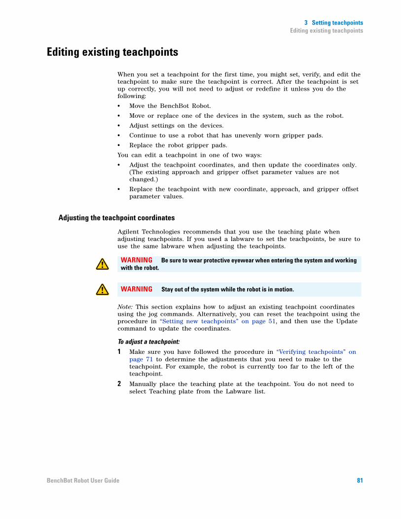
3 Setting teachpointsEditing existing teachpoints
Editing existing teachpoints
When you set a teachpoint for the first time, you might set, verify, and edit the teachpoint to make sure the teachpoint is correct. After the teachpoint is set up correctly, you will not need to adjust or redefine it unless you do the following:
• Move the BenchBot Robot.
• Move or replace one of the devices in the system, such as the robot.
• Adjust settings on the devices.
• Continue to use a robot that has unevenly worn gripper pads.
• Replace the robot gripper pads.
You can edit a teachpoint in one of two ways:
• Adjust the teachpoint coordinates, and then update the coordinates only. (The existing approach and gripper offset parameter values are not changed.)
• Replace the teachpoint with new coordinate, approach, and gripper offset parameter values.
Adjusting the teachpoint coordinates
Agilent Technologies recommends that you use the teaching plate when adjusting teachpoints. If you used a labware to set the teachpoints, be sure to use the same labware when adjusting the teachpoints.
Note: This section explains how to adjust an existing teachpoint coordinates using the jog commands. Alternatively, you can reset the teachpoint using the procedure in “Setting new teachpoints” on page 51, and then use the Update command to update the coordinates.
To adjust a teachpoint:
1 Make sure you have followed the procedure in “Verifying teachpoints” on page 71 to determine the adjustments that you need to make to the teachpoint. For example, the robot is currently too far to the left of the teachpoint.
2 Manually place the teaching plate at the teachpoint. You do not need to select Teaching plate from the Labware list.
WARNING Be sure to wear protective eyewear when entering the system and working with the robot.
WARNING Stay out of the system while the robot is in motion.
81BenchBot Robot User Guide
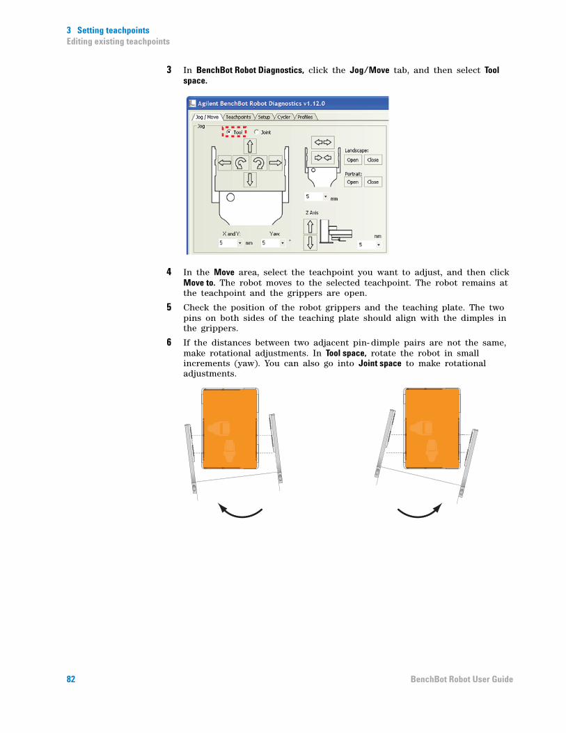
3 Setting teachpointsEditing existing teachpoints
3 In BenchBot Robot Diagnostics, click the Jog/Move tab, and then select Tool space.
4 In the Move area, select the teachpoint you want to adjust, and then click Move to. The robot moves to the selected teachpoint. The robot remains at the teachpoint and the grippers are open.
5 Check the position of the robot grippers and the teaching plate. The two pins on both sides of the teaching plate should align with the dimples in the grippers.
6 If the distances between two adjacent pin- dimple pairs are not the same, make rotational adjustments. In Tool space, rotate the robot in small increments (yaw). You can also go into Joint space to make rotational adjustments.
82 BenchBot Robot User Guide
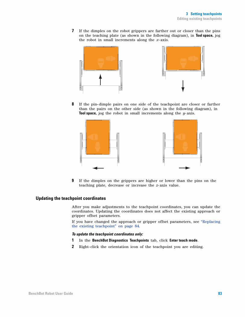
3 Setting teachpointsEditing existing teachpoints
7 If the dimples on the robot grippers are farther out or closer than the pins on the teaching plate (as shown in the following diagram), in Tool space, jog the robot in small increments along the x- axis.
8 If the pin- dimple pairs on one side of the teachpoint are closer or farther than the pairs on the other side (as shown in the following diagram), in Tool space, jog the robot in small increments along the y- axis.
9 If the dimples on the grippers are higher or lower than the pins on the teaching plate, decrease or increase the z- axis value.
Updating the teachpoint coordinates
After you make adjustments to the teachpoint coordinates, you can update the coordinates. Updating the coordinates does not affect the existing approach or gripper offset parameters.
If you have changed the approach or gripper offset parameters, see “Replacing the existing teachpoint” on page 84.
To update the teachpoint coordinates only:
1 In the BenchBot Diagnostics Teachpoints tab, click Enter teach mode.
2 Right- click the orientation icon of the teachpoint you are editing.
83BenchBot Robot User Guide
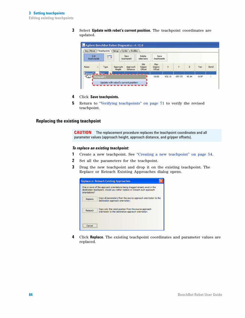
3 Setting teachpointsEditing existing teachpoints
3 Select Update with robot’s current position. The teachpoint coordinates are updated.
4 Click Save teachpoints.
5 Return to “Verifying teachpoints” on page 71 to verify the revised teachpoint.
Replacing the existing teachpoint
To replace an existing teachpoint:
1 Create a new teachpoint. See “Creating a new teachpoint” on page 54.
2 Set all the parameters for the teachpoint.
3 Drag the new teachpoint and drop it on the existing teachpoint. The Replace or Reteach Existing Approaches dialog opens.
4 Click Replace. The existing teachpoint coordinates and parameter values are replaced.
CAUTION The replacement procedure replaces the teachpoint coordinates and all parameter values (approach height, approach distance, and gripper offsets).
84 BenchBot Robot User Guide

3 Setting teachpointsEditing existing teachpoints
Related information
For information about... See...
Verifying teachpoints “Verifying teachpoints” on page 71
Managing teachpoints “Managing teachpoints” on page 86
Cycling teachpoints “Cycling teachpoints” on page 87
85BenchBot Robot User Guide

3 Setting teachpointsManaging teachpoints
Managing teachpoints
You can rename, copy, or delete existing teachpoints.
Before you start
Make sure you are in the teach mode. In the BenchBot Diagnostics Teachpoints tab, click Enter teach mode.
Renaming teachpoints
To rename a teachpoint:
1 In the Teachpoints tab, select the teachpoint you want to rename.
2 Double- click the teachpoint name, and then type a new name.
3 Click Save teachpoints to save the changes in the teachpoint file.
Copying teachpoints
You can use a copy of a teachpoint to create a new teachpoint.
To create a copy of a teachpoint:
1 In the Teachpoints tab, click New Teachpoint. A new teachpoint entry appears at the bottom of the table.
2 Select the teachpoint you want to copy.
3 With the teachpoint selected, Ctrl+drag the teachpoint to the new teachpoint entry.
4 Modify the copy to create a new teachpoint.
5 Click Save teachpoints to save the changes in the teachpoint file.
Deleting teachpoints
To delete a teachpoint:
1 In the Teachpoints tab, select one or more teachpoints you want to delete in the teachpoints table.
2 Click Delete selections.
3 Click Save teachpoints to save the changes in the teachpoint file.
Related information
For information about... See...
Verifying teachpoints “Verifying teachpoints” on page 71
Editing teachpoints “Editing existing teachpoints” on page 81
Cycling teachpoints “Cycling teachpoints” on page 87
86 BenchBot Robot User Guide

3 Setting teachpointsCycling teachpoints
Cycling teachpoints
About teachpoint cycling
After you have set and verified each teachpoint, you can have the robot transfer labware to and from multiple teachpoints in a cycling pattern as a final check. You can select the teachpoints you want to verify and specify the sequence in which the transfers will occur. Doing so allows you to check the accuracy of the selected teachpoints without having to write or run a protocol.
Cycling sequences
Two types of teachpoint- cycling sequences are available: Sequential, and all permutations.
SequentialIn sequential cycling, the robot will transfer labware to the selected teachpoints in the order you specify. For example, if you select four teachpoints (1, 2, 3, and 4), the cycling order is as follows:
All permutationsIn all- permutations cycling, the robot will transfer labware to each of the the selected teachpoints in all of the possible permutations. If a teachpoint has more than one orientation, all of the orientations will be cycled.
Before you start
Plate stages
IMPORTANT Make sure the device plate stages are extended so that the robot can place labware at these teachpoints during cycling.
The cycling function is a feature of BenchBot Robot Diagnostics only. During cycling, the VWorks software does not send commands to the devices to open device doors or extend the plate stages. Therefore, you must use the commands in the device diagnostics to move the plate stages into positions before cycling the teachpoints. For instructions on how to move the plate stages into position, see the device user guide.
Labware lidsThe only actions the robot will perform during cycling is picking up and placing labware. You cannot delid or relid labware during the cycling process.
1
4
3
2
87BenchBot Robot User Guide

3 Setting teachpointsCycling teachpoints
Procedure
To transfer labware between multiple teachpoints:
1 In BenchBot Robot Diagnostics, click the Cycler tab.
2 Click Add teachpoints. The Add Cycler Teachpoints dialog box opens.
3 Select the teachpoints you want to verify. CRTL+click multiple teachpoints to add them simultaneously.
WARNING Be sure to wear protective eyewear when entering the system and working with the robot.
WARNING Stay out of the system while the robot is in motion.
88 BenchBot Robot User Guide
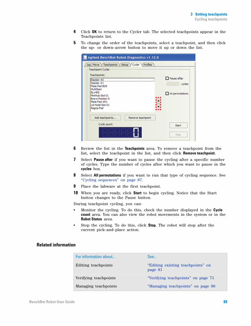
3 Setting teachpointsCycling teachpoints
4 Click OK to return to the Cycler tab. The selected teachpoints appear in the Teachpoints list.
5 To change the order of the teachpoints, select a teachpoint, and then click the up- or down- arrow button to move it up or down the list.
6 Review the list in the Teachpoints area. To remove a teachpoint from the list, select the teachpoint in the list, and then click Remove teachpoint.
7 Select Pause after if you want to pause the cycling after a specific number of cycles. Type the number of cycles after which you want to pause in the cycles box.
8 Select All permutations if you want to run that type of cycling sequence. See “Cycling sequences” on page 87.
9 Place the labware at the first teachpoint.
10 When you are ready, click Start to begin cycling. Notice that the Start button changes to the Pause button.
During teachpoint cycling, you can:
• Monitor the cycling. To do this, check the number displayed in the Cycle count area. You can also view the robot movements in the system or in the Robot Status area.
• Stop the cycling. To do this, click Stop. The robot will stop after the current pick- and- place action.
Related information
For information about... See...
Editing teachpoints “Editing existing teachpoints” on page 81
Verifying teachpoints “Verifying teachpoints” on page 71
Managing teachpoints “Managing teachpoints” on page 86
89BenchBot Robot User Guide

3 Setting teachpointsCycling teachpoints
90 BenchBot Robot User Guide
BenchBot RobotUser Guide
4Preparing for a protocol run
Before you start a protocol run, you should check the BenchBot Robot teachpoints and the protocol to ensure optimum operation.
This chapter contains the following topics:
• “Workflow for preparing a protocol run” on page 92
• “Planning for the protocol run” on page 93
• “Performing dry runs” on page 94
• “Stopping the robot in an emergency” on page 95
91
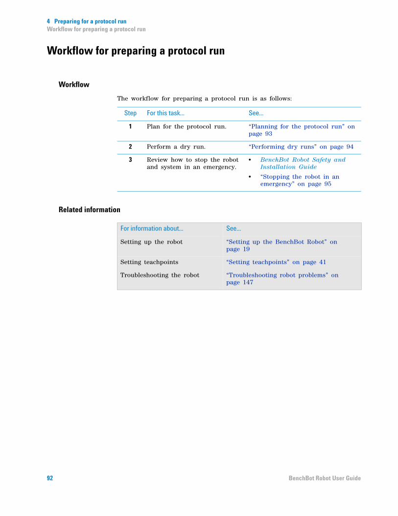
4 Preparing for a protocol runWorkflow for preparing a protocol run
Workflow for preparing a protocol run
Workflow
The workflow for preparing a protocol run is as follows:
Related information
Step For this task... See...
1 Plan for the protocol run. “Planning for the protocol run” on page 93
2 Perform a dry run. “Performing dry runs” on page 94
3 Review how to stop the robot and system in an emergency.
• BenchBot Robot Safety and Installation Guide
• “Stopping the robot in an emergency” on page 95
For information about... See...
Setting up the robot “Setting up the BenchBot Robot” on page 19
Setting teachpoints “Setting teachpoints” on page 41
Troubleshooting the robot “Troubleshooting robot problems” on page 147
92 BenchBot Robot User Guide
4 Preparing for a protocol runPlanning for the protocol run
Planning for the protocol run
Reviewing the protocol
Before you start a run, make sure you review the protocol and determine:
• The devices used in the protocol and how to prepare them for operation. For example, you might need to load a roll of seal on the PlateLoc Sealer or install a pipette head on a Vertical Pipetting Station. See the device user guides for setup instructions.
• The optimal device setup sequence. In general, you first set up devices that do not hold time- sensitive reagents. Leave complex preparations, which might use expensive and unstable reagents, until last.
• The labware used in the protocol and where they should be positioned before the run starts. For example, you might have to load labware into one or more storage devices such as the Labware Stacker and the Plate Hub.
• The waste bins that should be emptied.
• The reservoirs that must be filled.
Be sure to check the protocol User Message tasks for setup information. If the User Message tasks prompt you to place counterweight labware, you do not have to include these steps in the setup.
Reviewing the teachpoint file
Before loading labware in storage devices, always review the teachpoint file for labware orientation information. The labware must be loaded in the same orientation as specified in the teachpoint file. In addition, load the labware such that their barcodes will not be obstructed by the robot grippers.
Related information
For information about... See...
Creating or revising protocols VWorks Automation Control User Guide
Performing dry runs “Performing dry runs” on page 94
Stopping the robot in an emergency
“Stopping the robot in an emergency” on page 95
93BenchBot Robot User Guide
4 Preparing for a protocol runPerforming dry runs
Performing dry runs
What is a dry run?
A dry run is when you run a protocol using empty labware. A dry run allows you to troubleshoot a protocol or a component of the system without wasting valuable reagents and samples. You should always perform a dry run to check a new protocol.
Correcting teachpoint errors
After setting the teachpoints, be sure to perform a dry run as a final check for any teachpoint errors. The dry run also allows you to fine- tune orientation settings in the system.
Preparing for a dry run
You prepare for a dry run the same way you would prepare for a real protocol run. To review the protocol before a dry run, see “Planning for the protocol run” on page 93.
Related information
For information about... See...
Writing protocols VWorks Automation Control User Guide
Preparing for a run “Workflow for preparing a protocol run” on page 92
Setting teachpoints “Setting teachpoints” on page 41
Troubleshooting the robot “Troubleshooting robot problems” on page 147
94 BenchBot Robot User Guide
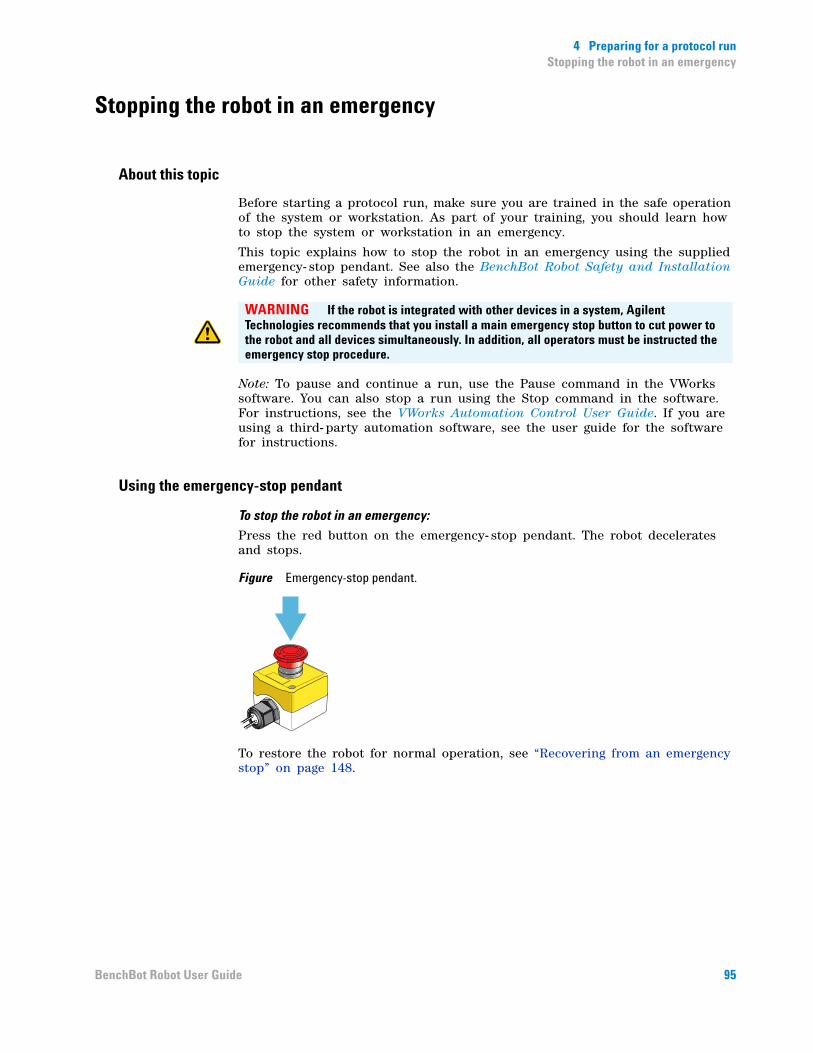
4 Preparing for a protocol runStopping the robot in an emergency
Stopping the robot in an emergency
About this topic
Before starting a protocol run, make sure you are trained in the safe operation of the system or workstation. As part of your training, you should learn how to stop the system or workstation in an emergency.
This topic explains how to stop the robot in an emergency using the supplied emergency- stop pendant. See also the BenchBot Robot Safety and Installation Guide for other safety information.
Note: To pause and continue a run, use the Pause command in the VWorks software. You can also stop a run using the Stop command in the software. For instructions, see the VWorks Automation Control User Guide. If you are using a third- party automation software, see the user guide for the software for instructions.
Using the emergency-stop pendant
To stop the robot in an emergency:
Press the red button on the emergency- stop pendant. The robot decelerates and stops.
Figure Emergency-stop pendant.
To restore the robot for normal operation, see “Recovering from an emergency stop” on page 148.
WARNING If the robot is integrated with other devices in a system, Agilent Technologies recommends that you install a main emergency stop button to cut power to the robot and all devices simultaneously. In addition, all operators must be instructed the emergency stop procedure.
95BenchBot Robot User Guide
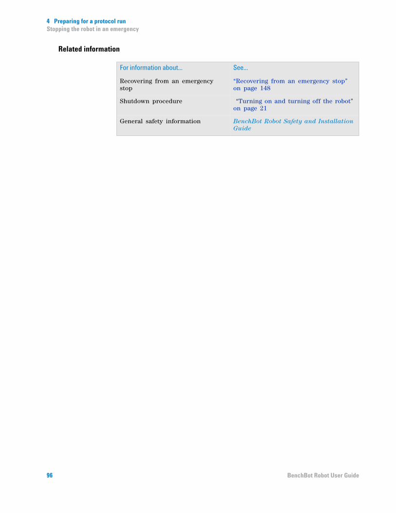
4 Preparing for a protocol runStopping the robot in an emergency
Related information
For information about... See...
Recovering from an emergency stop
“Recovering from an emergency stop” on page 148
Shutdown procedure “Turning on and turning off the robot” on page 21
General safety information BenchBot Robot Safety and Installation Guide
96 BenchBot Robot User Guide

BenchBot RobotUser Guide
5Using BenchBot Diagnostics
This chapter explains how to use BenchBot Diagnostics to diagnose and troubleshoot the BenchBot Robot.
This chapter contains the following topics:
• “About BenchBot Robot Diagnostics” on page 98
• “Checking the robot status and log” on page 100
• “Homing the robot and grippers” on page 103
• “Retracting the robot into the robot zone” on page 106
• “Jogging the robot” on page 109
• “Disabling and enabling the robot joint motors” on page 113
• “Stopping the robot motors” on page 115
• “Changing the robot speed” on page 117
• “Changing the robot speed definitions” on page 119
• “Opening and closing the robot grippers” on page 122
• “Changing the gripper settings” on page 125
• “Updating the firmware” on page 127
• “Backing up the robot firmware” on page 129
• “Installing new or restoring existing firmware” on page 131
WARNING Only administrators and trained personnel should perform the procedures in this chapter.
97
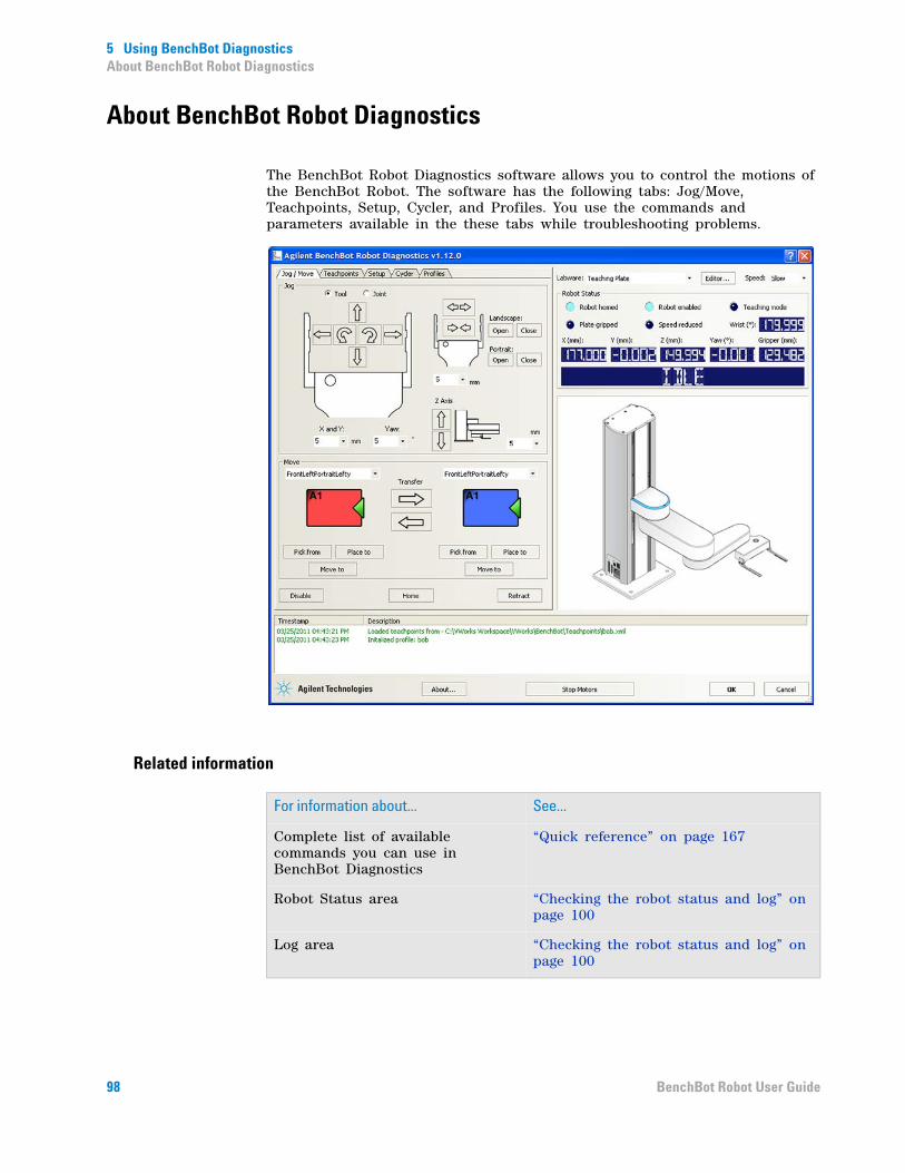
5 Using BenchBot DiagnosticsAbout BenchBot Robot Diagnostics
About BenchBot Robot Diagnostics
The BenchBot Robot Diagnostics software allows you to control the motions of the BenchBot Robot. The software has the following tabs: Jog/Move, Teachpoints, Setup, Cycler, and Profiles. You use the commands and parameters available in the these tabs while troubleshooting problems.
Related information
For information about... See...
Complete list of available commands you can use in BenchBot Diagnostics
“Quick reference” on page 167
Robot Status area “Checking the robot status and log” on page 100
Log area “Checking the robot status and log” on page 100
98 BenchBot Robot User Guide
5 Using BenchBot DiagnosticsAbout BenchBot Robot Diagnostics
Jog/Move tab • “Stopping the robot motors” on page 115
• “Jogging the robot” on page 109
• “Opening and closing the robot grippers” on page 122
• “Homing the robot and grippers” on page 103
• “Verifying teachpoints” on page 71
• “Retracting the robot into the robot zone” on page 106
Teachpoints tab • “Setting new teachpoints” on page 51
• “Editing existing teachpoints” on page 81
Cycler tab “Cycling teachpoints” on page 87
Setup tab • “Changing the robot speed definitions” on page 119
• “Changing the gripper settings” on page 125
• “Updating the firmware” on page 127
• “Backing up the robot firmware” on page 129
• “Installing new or restoring existing firmware” on page 131
Profiles tab “Creating BenchBot Robot profiles” on page 29
For information about... See...
99BenchBot Robot User Guide

5 Using BenchBot DiagnosticsChecking the robot status and log
Checking the robot status and log
About the robot status and log
Information in the Robot Status and log areas can provide helpful information when you are trying to troubleshoot and resolve problems. The Robot Status and log areas are not tab- dependent and are always visible.
The Robot Status area tells you the current position of the robot, whether the robot is in its home position, whether the motors are enabled, and whether a labware is in its grippers. The log area provides a detailed list of commands and actions the robot has executed.
Checking the robot status
To check the robot status:View the Robot Status area in BenchBot Diagnostics. The Robot Status area displays the following information:
Label Description
Robot homed Indicates that the robot has homed successfully.
Robot enabled Indicates whether the robot motors are enabled.
Teaching mode Indicates if the robot is in the teach mode.
Plate gripped Indicates if a labware is in the robot’s grippers.
Speed reduced Indicates that the robot is moving in the reduced-speed mode.
X (mm) Displays the current x- axis coordinate of the center of the labware, in millimeters.
Y (mm) Displays the current y- axis coordinate of the center of the labware, in millimeters.
Z (mm) Displays the current z- axis coordinate of the center of the labware, in millimeters.
Yaw (°) Displays the angle between the grippers and the x- axis, in degrees.
Gripper (mm) Displays the current distance between the inside surface of the grippers, in millimeters.
100 BenchBot Robot User Guide

5 Using BenchBot DiagnosticsChecking the robot status and log
Checking the log
To check the log:
View the log area at the bottom of the BenchBot Diagnostics dialog box.
The log area shows the status of the commands or actions issued while you are working in the dialog box.
Related information
Wrist (°) Displays the angle between the robot hand and the forearm, in degrees.
Status message Displays the robot status, including:
• NOT CONNECTED. The robot is not initialized or is not connected to the controlling computer.
• IDLE. The robot is initialized and is in the ready state.
• HOMING. The robot is in the process of homing.
• UNWINDING. The robot is in the process of homing the wrist.
Label Description
For information about... See...
Homing the robot “Homing the robot and grippers” on page 103
Moving the robot into the robot zone
“Retracting the robot into the robot zone” on page 106
Disabling and enabling the robot motor
“Disabling and enabling the robot joint motors” on page 113
Stopping the robot motors “Stopping the robot motors” on page 115
Changing the robot speed “Changing the robot speed” on page 117
Changing the robot speed definitions
“Changing the robot speed definitions” on page 119
Jogging the robot “Jogging the robot” on page 109
Opening and closing the robot grippers
“Opening and closing the robot grippers” on page 122
101BenchBot Robot User Guide

5 Using BenchBot DiagnosticsChecking the robot status and log
Changing the gripper settings “Changing the gripper settings” on page 125
Updating the firmware “Updating the firmware” on page 127
Backing up the robot firmware “Backing up the robot firmware” on page 129
Installing new or restoring existing firmware
“Installing new or restoring existing firmware” on page 131
For information about... See...
102 BenchBot Robot User Guide

5 Using BenchBot DiagnosticsHoming the robot and grippers
Homing the robot and grippers
About the homing process
The homing process does the following:
• Initializes the encoders with the correct position information.
• Retracts the robot to its neutral position in the robot zone. The following diagram shows the top view (left) and side view (right) of the robot in the neutral position.
The neutral position coordinates are:
Note: When homed, the grippers are 130 mm apart as measured from the inside surfaces.
Axis Coordinate value
X 177 mm
Y 0 mm
Z 150 mm
Yaw 0°
Gripper 130 mm
103BenchBot Robot User Guide

5 Using BenchBot DiagnosticsHoming the robot and grippers
Home the robot after turning on the robot, recovering from an emergency stop, or recovering from a crash.
Before you start
Make sure you enable the robot motors before homing. In the Jog/Move tab, click Enable.
Procedure
To home the robot:
In the Jog/Move tab, click Home.
The homing process takes less than 30 seconds. During this time, the robot:
• Closes its grippers slightly to check for the presence of labware in its grippers. If labware is present, the software will display an error message. Remove the labware and click Home again.
• Opens the grippers to its maximum open position of 134 mm, and then closes the grippers to 130 mm.
• Reads the encoders to obtain the current positions of the joints.
• Rotates the wrist so that it is at the home position.
WARNING Be sure to wear protective eyewear when entering the system and working with the robot.
WARNING Stay out of the system while the robot is in motion.
104 BenchBot Robot User Guide

5 Using BenchBot DiagnosticsHoming the robot and grippers
After the robot homes successfully, the Robot homed indicator light turns on.
Related information
For information about... See...
Moving the robot into the robot zone
“Retracting the robot into the robot zone” on page 106
Disabling and enabling the robot motor
“Disabling and enabling the robot joint motors” on page 113
Stopping the robot motors “Stopping the robot motors” on page 115
Changing the robot speed “Changing the robot speed” on page 117
Changing the robot speed definitions
“Changing the robot speed definitions” on page 119
Jogging the robot “Jogging the robot” on page 109
Opening and closing the robot grippers
“Opening and closing the robot grippers” on page 122
Changing the gripper settings “Changing the gripper settings” on page 125
View the Robot Status area “Checking the robot status and log” on page 100
Viewing the log area “Checking the robot status and log” on page 100
Updating the firmware “Updating the firmware” on page 127
Backing up the robot firmware “Backing up the robot firmware” on page 129
Installing new or restoring existing firmware
“Installing new or restoring existing firmware” on page 131
105BenchBot Robot User Guide
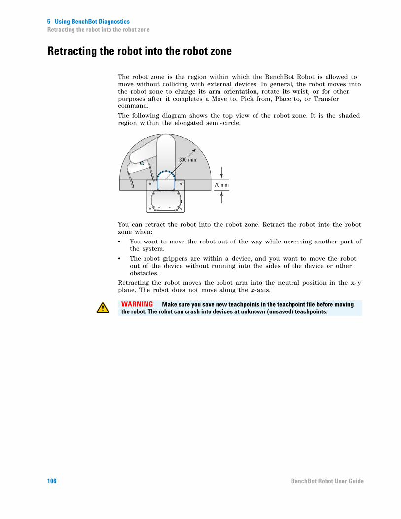
5 Using BenchBot DiagnosticsRetracting the robot into the robot zone
Retracting the robot into the robot zone
The robot zone is the region within which the BenchBot Robot is allowed to move without colliding with external devices. In general, the robot moves into the robot zone to change its arm orientation, rotate its wrist, or for other purposes after it completes a Move to, Pick from, Place to, or Transfer command.
The following diagram shows the top view of the robot zone. It is the shaded region within the elongated semi- circle.
You can retract the robot into the robot zone. Retract the robot into the robot zone when:
• You want to move the robot out of the way while accessing another part of the system.
• The robot grippers are within a device, and you want to move the robot out of the device without running into the sides of the device or other obstacles.
Retracting the robot moves the robot arm into the neutral position in the x- y plane. The robot does not move along the z- axis.
70 mm
300 mm
WARNING Make sure you save new teachpoints in the teachpoint file before moving the robot. The robot can crash into devices at unknown (unsaved) teachpoints.
106 BenchBot Robot User Guide
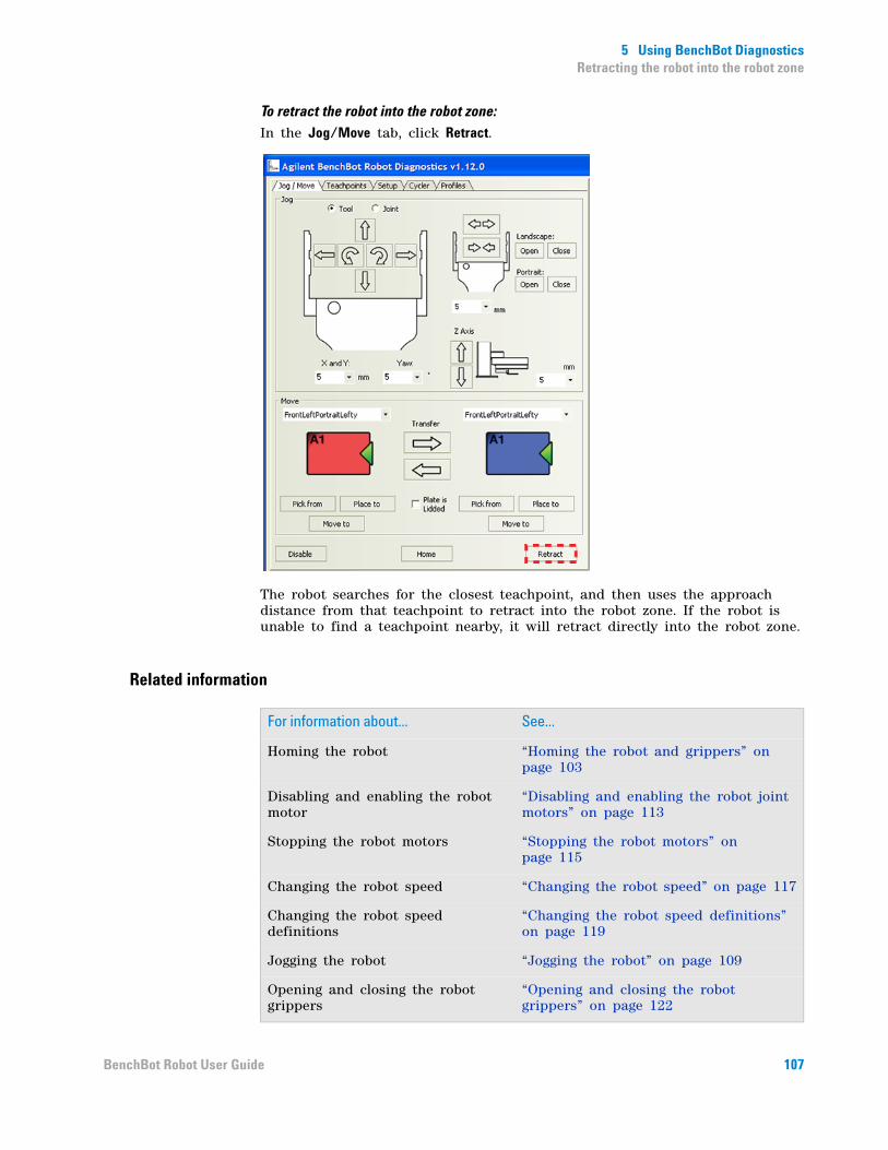
5 Using BenchBot DiagnosticsRetracting the robot into the robot zone
To retract the robot into the robot zone:In the Jog/Move tab, click Retract.
The robot searches for the closest teachpoint, and then uses the approach distance from that teachpoint to retract into the robot zone. If the robot is unable to find a teachpoint nearby, it will retract directly into the robot zone.
Related information
For information about... See...
Homing the robot “Homing the robot and grippers” on page 103
Disabling and enabling the robot motor
“Disabling and enabling the robot joint motors” on page 113
Stopping the robot motors “Stopping the robot motors” on page 115
Changing the robot speed “Changing the robot speed” on page 117
Changing the robot speed definitions
“Changing the robot speed definitions” on page 119
Jogging the robot “Jogging the robot” on page 109
Opening and closing the robot grippers
“Opening and closing the robot grippers” on page 122
107BenchBot Robot User Guide

5 Using BenchBot DiagnosticsRetracting the robot into the robot zone
Changing the gripper settings “Changing the gripper settings” on page 125
View the Robot Status area “Checking the robot status and log” on page 100
Viewing the log area “Checking the robot status and log” on page 100
Updating the firmware “Updating the firmware” on page 127
Backing up the robot firmware “Backing up the robot firmware” on page 129
Installing new or restoring existing firmware
“Installing new or restoring existing firmware” on page 131
For information about... See...
108 BenchBot Robot User Guide

5 Using BenchBot DiagnosticsJogging the robot
Jogging the robot
About this topic
Jogging the robot moves the robot in small, precise increments. You can jog the robot to fine- tune its position when creating and editing teachpoints or during troubleshooting.
The BenchBot Robot movements can be controlled or monitored from two different perspectives:
• Joint space
• Tool space
This topic explains how the two perspectives are different and how to jog the robot in each perspective.
Joint space
You can use a joint- space command to rotate the robot about its shoulder (1), rotate its forearm about the elbow (2), or rotate the hand about the wrist (3). In addition, you can move the robot arm up and down along the mast or z-axis (4).
Tool space
You can use a tool- space command to move a combination of robot joints so that the labware moves to its target location, (x, y, z, yaw). In tool space, all movements are relative to the current position of the center of the labware.
2
1
3
4
+ x
+ z
+ y
+
-
109BenchBot Robot User Guide

5 Using BenchBot DiagnosticsJogging the robot
Procedure
To select a perspective:In the Jog/Move tab, select Tool or Joint.
To jog the robot:
1 Select or type the jog increment for the axis or joint you want to move. The jog increments are in millimeters or degrees.
CAUTION Always select small jog increments so that the robot does not bump into obstacles in its path.
110 BenchBot Robot User Guide

5 Using BenchBot DiagnosticsJogging the robot
2 Click one of the jog direction buttons.
In the Robot Status area, the robot coordinates are updated.
Related information
WARNING Stay out of the system while the robot is in motion.
For information about... See...
Homing the robot “Homing the robot and grippers” on page 103
Moving the robot into the robot zone
“Retracting the robot into the robot zone” on page 106
Disabling and enabling the robot motor
“Disabling and enabling the robot joint motors” on page 113
Stopping the robot motors “Stopping the robot motors” on page 115
Changing the robot speed “Changing the robot speed” on page 117
Changing the robot speed definitions
“Changing the robot speed definitions” on page 119
Opening and closing the robot grippers
“Opening and closing the robot grippers” on page 122
Changing the gripper settings “Changing the gripper settings” on page 125
View the Robot Status area “Checking the robot status and log” on page 100
111BenchBot Robot User Guide
5 Using BenchBot DiagnosticsJogging the robot
Viewing the log area “Checking the robot status and log” on page 100
Updating the firmware “Updating the firmware” on page 127
Backing up the robot firmware “Backing up the robot firmware” on page 129
Installing new or restoring existing firmware
“Installing new or restoring existing firmware” on page 131
Setting teachpoints “Setting teachpoints” on page 41
Moving labware between teachpoints
• “Moving the robot to the new teachpoint” on page 71
• “Picking up labware at the teachpoint” on page 74
• “Placing labware at the teachpoint” on page 76
• “Transferring labware between two teachpoints” on page 78
For information about... See...
112 BenchBot Robot User Guide
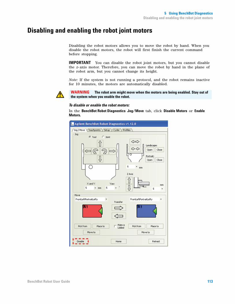
5 Using BenchBot DiagnosticsDisabling and enabling the robot joint motors
Disabling and enabling the robot joint motors
Disabling the robot motors allows you to move the robot by hand. When you disable the robot motors, the robot will first finish the current command before stopping.
IMPORTANT You can disable the robot joint motors, but you cannot disable the z- axis motor. Therefore, you can move the robot by hand in the plane of the robot arm, but you cannot change its height.
Note: If the system is not running a protocol, and the robot remains inactive for 10 minutes, the motors are automatically disabled.
To disable or enable the robot motors:In the BenchBot Robot Diagnostics Jog/Move tab, click Disable Motors or Enable Motors.
WARNING The robot arm might move when the motors are being enabled. Stay out of the system when you enable the robot.
113BenchBot Robot User Guide

5 Using BenchBot DiagnosticsDisabling and enabling the robot joint motors
Related information
For information about... See...
Homing the robot “Homing the robot and grippers” on page 103
Moving the robot into the robot zone
“Retracting the robot into the robot zone” on page 106
Stopping the robot motors “Stopping the robot motors” on page 115
Changing the robot speed “Changing the robot speed” on page 117
Changing the robot speed definitions
“Changing the robot speed definitions” on page 119
Opening and closing the robot grippers
“Opening and closing the robot grippers” on page 122
Changing the gripper settings “Changing the gripper settings” on page 125
View the Robot Status area “Checking the robot status and log” on page 100
Viewing the log area “Checking the robot status and log” on page 100
Updating the firmware “Updating the firmware” on page 127
Backing up the robot firmware “Backing up the robot firmware” on page 129
Installing new or restoring existing firmware
“Installing new or restoring existing firmware” on page 131
Setting teachpoints “Setting teachpoints” on page 41
Moving labware between teachpoints
• “Moving the robot to the new teachpoint” on page 71
• “Picking up labware at the teachpoint” on page 74
• “Placing labware at the teachpoint” on page 76
• “Transferring labware between two teachpoints” on page 78
114 BenchBot Robot User Guide
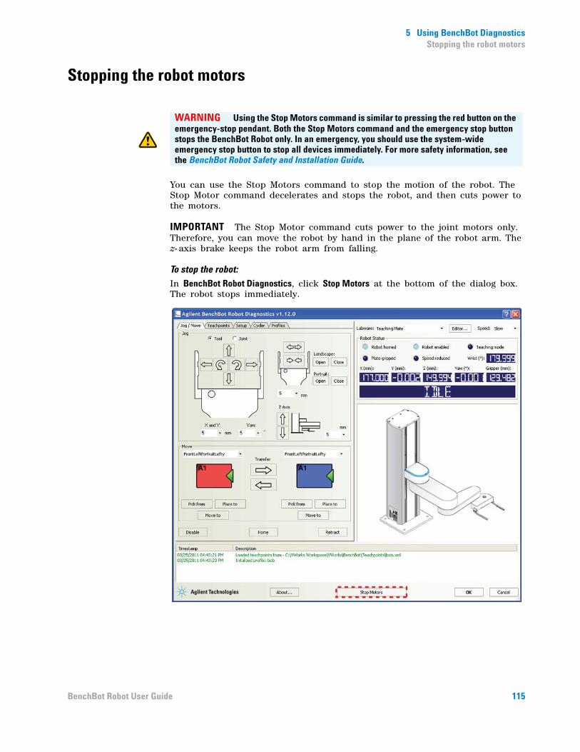
5 Using BenchBot DiagnosticsStopping the robot motors
Stopping the robot motors
You can use the Stop Motors command to stop the motion of the robot. The Stop Motor command decelerates and stops the robot, and then cuts power to the motors.
IMPORTANT The Stop Motor command cuts power to the joint motors only. Therefore, you can move the robot by hand in the plane of the robot arm. The z- axis brake keeps the robot arm from falling.
To stop the robot:
In BenchBot Robot Diagnostics, click Stop Motors at the bottom of the dialog box. The robot stops immediately.
WARNING Using the Stop Motors command is similar to pressing the red button on the emergency-stop pendant. Both the Stop Motors command and the emergency stop button stops the BenchBot Robot only. In an emergency, you should use the system-wide emergency stop button to stop all devices immediately. For more safety information, see the BenchBot Robot Safety and Installation Guide.
115BenchBot Robot User Guide

5 Using BenchBot DiagnosticsStopping the robot motors
Related information
For information about... See...
Stopping the robot in an emergency using the emergency-stop pendant
“Stopping the robot in an emergency” on page 95
Homing the robot “Homing the robot and grippers” on page 103
Moving the robot into the robot zone
“Retracting the robot into the robot zone” on page 106
Disabling and enabling the robot motor
“Disabling and enabling the robot joint motors” on page 113
Changing the robot speed “Changing the robot speed” on page 117
Changing the robot speed definitions
“Changing the robot speed definitions” on page 119
Jogging the robot “Jogging the robot” on page 109
Opening and closing the robot grippers
“Opening and closing the robot grippers” on page 122
Changing the gripper settings “Changing the gripper settings” on page 125
View the Robot Status area “Checking the robot status and log” on page 100
Viewing the log area “Checking the robot status and log” on page 100
Updating the firmware “Updating the firmware” on page 127
Backing up the robot firmware “Backing up the robot firmware” on page 129
Installing new or restoring existing firmware
“Installing new or restoring existing firmware” on page 131
116 BenchBot Robot User Guide
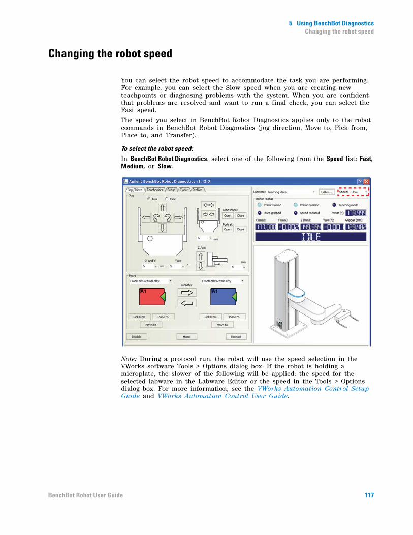
5 Using BenchBot DiagnosticsChanging the robot speed
Changing the robot speed
You can select the robot speed to accommodate the task you are performing. For example, you can select the Slow speed when you are creating new teachpoints or diagnosing problems with the system. When you are confident that problems are resolved and want to run a final check, you can select the Fast speed.
The speed you select in BenchBot Robot Diagnostics applies only to the robot commands in BenchBot Robot Diagnostics (jog direction, Move to, Pick from, Place to, and Transfer).
To select the robot speed:In BenchBot Robot Diagnostics, select one of the following from the Speed list: Fast, Medium, or Slow.
Note: During a protocol run, the robot will use the speed selection in the VWorks software Tools > Options dialog box. If the robot is holding a microplate, the slower of the following will be applied: the speed for the selected labware in the Labware Editor or the speed in the Tools > Options dialog box. For more information, see the VWorks Automation Control Setup Guide and VWorks Automation Control User Guide.
117BenchBot Robot User Guide
5 Using BenchBot DiagnosticsChanging the robot speed
Related information
For information about... See...
Homing the robot “Homing the robot and grippers” on page 103
Moving the robot into the robot zone
“Retracting the robot into the robot zone” on page 106
Disabling and enabling the robot motor
“Disabling and enabling the robot joint motors” on page 113
Stopping the robot motors “Stopping the robot motors” on page 115
Changing the robot speed definitions
“Changing the robot speed definitions” on page 119
Jogging the robot “Jogging the robot” on page 109
Opening and closing the robot grippers
“Opening and closing the robot grippers” on page 122
Changing the gripper settings “Changing the gripper settings” on page 125
View the Robot Status area “Checking the robot status and log” on page 100
Viewing the log area “Checking the robot status and log” on page 100
Updating the firmware “Updating the firmware” on page 127
Backing up the robot firmware “Backing up the robot firmware” on page 129
Installing new or restoring existing firmware
“Installing new or restoring existing firmware” on page 131
118 BenchBot Robot User Guide

5 Using BenchBot DiagnosticsChanging the robot speed definitions
Changing the robot speed definitions
About robot speeds
Three robot speeds (Fast, Medium, Slow) are available for selection in BenchBot Robot Diagnostics, VWorks Options (under the Tools menu), and Labware Editor. You select a robot speed to accommodate the task you are performing. For example, you can select the Slow speed when you are creating new teachpoints, creating and testing protocols, or diagnosing problems with the system.
Each speed is defined as a percentage of the factory- set maximum speed. By default, the percentages are defined as follows:
You can change these speed definitions to accommodate your laboratory’s needs.
IMPORTANT The speed definitions are universal and apply to the speeds you select in BenchBot Robot Diagnostics, Labware Editor, and the VWorks Options dialog box.
Note: The speed you select in BenchBot Robot Diagnostics applies only to the robot commands in BenchBot Robot Diagnostics (Jog, Move, Transfer, and so on). If the robot is holding a labware, the slower of the following will be applied: the speed you selected in the Labware Editor, or the speed you selected in BenchBot Robot Diagnostics.
Similarly the speed selection in VWorks Options (under the Tools menu) applies to protocol runs. If the robot is holding a labware, the slower of the following will be applied: the speed you selected in the Labware Editor, or the speed you selected in VWorks Options.
Speed Default
Slow 20%
Medium 50%
Fast 90%
119BenchBot Robot User Guide

5 Using BenchBot DiagnosticsChanging the robot speed definitions
Specifying new speed definitions
To change the speed definitions:
1 In BenchBot Robot Diagnostics, click the Setup tab.
2 In the Speeds area, type the new percentage for one or more of the speeds you want to re- define.
3 When you are finished, click Apply Setup Changes. The changes are saved to the firmware.
Related information
For information about... See...
Selecting a robot speed in BenchBot Robot Diagnostics
“Changing the robot speed” on page 117
Homing the robot “Homing the robot and grippers” on page 103
Moving the robot into the robot zone
“Retracting the robot into the robot zone” on page 106
Disabling and enabling the robot motor
“Disabling and enabling the robot joint motors” on page 113
Stopping the robot motors “Stopping the robot motors” on page 115
Jogging the robot “Jogging the robot” on page 109
Opening and closing the robot grippers
“Opening and closing the robot grippers” on page 122
Changing the gripper settings “Changing the gripper settings” on page 125
120 BenchBot Robot User Guide

5 Using BenchBot DiagnosticsChanging the robot speed definitions
View the Robot Status area “Checking the robot status and log” on page 100
Viewing the log area “Checking the robot status and log” on page 100
Updating the firmware “Updating the firmware” on page 127
Backing up the robot firmware “Backing up the robot firmware” on page 129
Installing new or restoring existing firmware
“Installing new or restoring existing firmware” on page 131
Selecting a robot speed in the Labware Editor
VWorks Automation Control Setup Guide
Selecting a robot speed in Protocol Options
VWorks Automation Control User Guide
For information about... See...
121BenchBot Robot User Guide
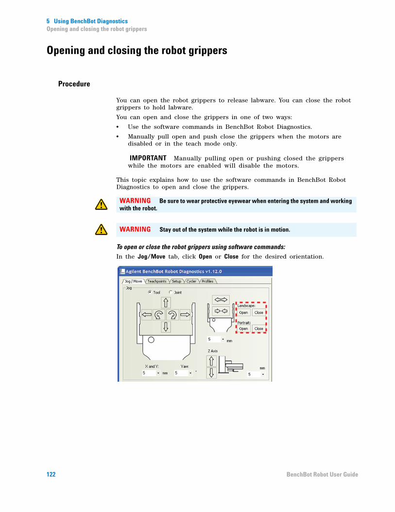
5 Using BenchBot DiagnosticsOpening and closing the robot grippers
Opening and closing the robot grippers
Procedure
You can open the robot grippers to release labware. You can close the robot grippers to hold labware.
You can open and close the grippers in one of two ways:
• Use the software commands in BenchBot Robot Diagnostics.
• Manually pull open and push close the grippers when the motors are disabled or in the teach mode only.
IMPORTANT Manually pulling open or pushing closed the grippers while the motors are enabled will disable the motors.
This topic explains how to use the software commands in BenchBot Robot Diagnostics to open and close the grippers.
To open or close the robot grippers using software commands:
In the Jog/Move tab, click Open or Close for the desired orientation.
WARNING Be sure to wear protective eyewear when entering the system and working with the robot.
WARNING Stay out of the system while the robot is in motion.
122 BenchBot Robot User Guide

5 Using BenchBot DiagnosticsOpening and closing the robot grippers
To open or close the grippers incrementally:
1 In the Jog/Move tab, select or type the jog increment for the grippers.
IMPORTANT The jog increment applies to both grip directions.
2 Click either the Open or Close gripper button.
Related information
CAUTION Always select smaller jog increments so that the robot does not bump into obstacles when it opens its grip, or bend the labware when it closes its grip.
For information about... See...
Homing the robot “Homing the robot and grippers” on page 103
Moving the robot into the robot zone
“Retracting the robot into the robot zone” on page 106
123BenchBot Robot User Guide
5 Using BenchBot DiagnosticsOpening and closing the robot grippers
Disabling and enabling the robot motor
“Disabling and enabling the robot joint motors” on page 113
Stopping the robot motors “Stopping the robot motors” on page 115
Changing the robot speed “Changing the robot speed” on page 117
Changing the robot speed definitions
“Changing the robot speed definitions” on page 119
Jogging the robot “Jogging the robot” on page 109
Changing the gripper settings “Changing the gripper settings” on page 125
View the Robot Status area “Checking the robot status and log” on page 100
Viewing the log area “Checking the robot status and log” on page 100
Updating the firmware “Updating the firmware” on page 127
Backing up the robot firmware “Backing up the robot firmware” on page 129
Installing new or restoring existing firmware
“Installing new or restoring existing firmware” on page 131
For information about... See...
124 BenchBot Robot User Guide
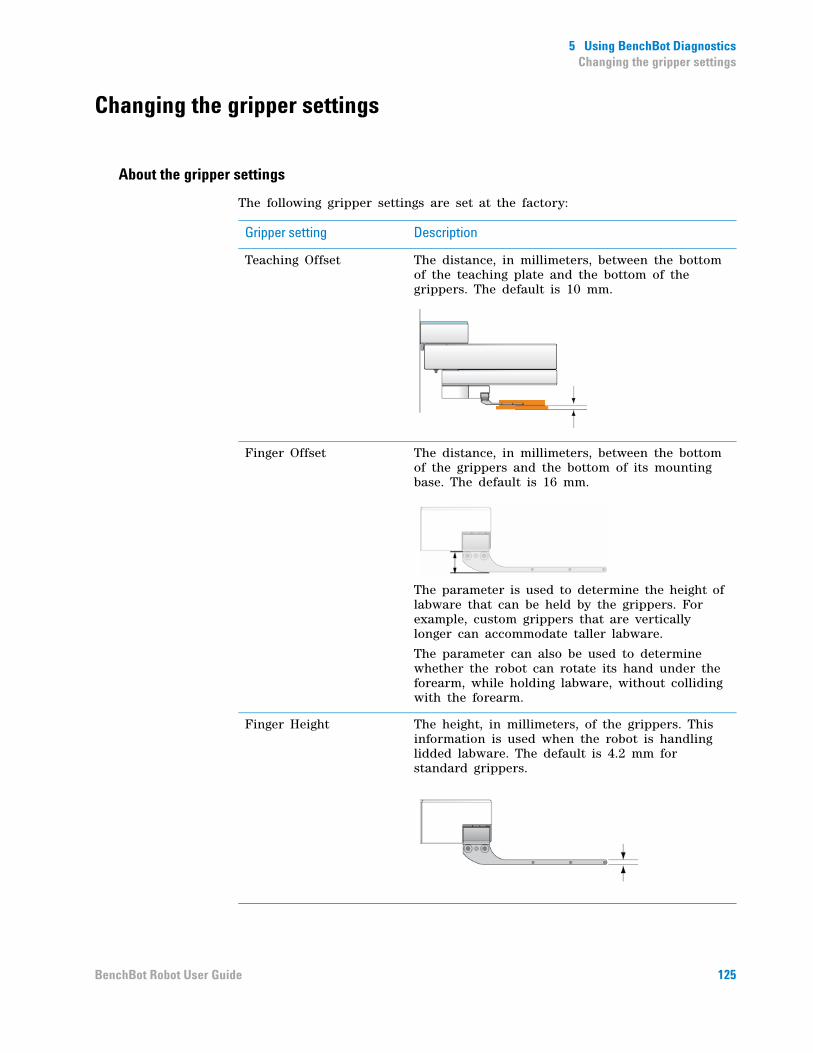
5 Using BenchBot DiagnosticsChanging the gripper settings
Changing the gripper settings
About the gripper settings
The following gripper settings are set at the factory:
Gripper setting Description
Teaching Offset The distance, in millimeters, between the bottom of the teaching plate and the bottom of the grippers. The default is 10 mm.
Finger Offset The distance, in millimeters, between the bottom of the grippers and the bottom of its mounting base. The default is 16 mm.
The parameter is used to determine the height of labware that can be held by the grippers. For example, custom grippers that are vertically longer can accommodate taller labware.
The parameter can also be used to determine whether the robot can rotate its hand under the forearm, while holding labware, without colliding with the forearm.
Finger Height The height, in millimeters, of the grippers. This information is used when the robot is handling lidded labware. The default is 4.2 mm for standard grippers.
125BenchBot Robot User Guide

5 Using BenchBot DiagnosticsChanging the gripper settings
The default gripper settings should work for labware that meet the American National Standards Institute (ANSI) standards. However, you can fine- tune the settings to accommodate different labware requirements and optimize performance.
Before you start
Agilent Technologies recommends that you back up the firmware before changing the gripper settings.
Specifying new settings
To change the gripper settings:
1 In BenchBot Robot Diagnostics, click the Setup tab.
2 In the Gripper Settings area, type the new values you want to use for Teaching Offset, Finger Offset, and Finger Height.
3 When you are finished, click Apply Setup Changes. The changes are saved to the firmware.
Related information
For information about... See...
Backing up firmware “Backing up the robot firmware” on page 129
Opening and closing the grippers using software controls
“Opening and closing the robot grippers” on page 122
Manually opening and closing the grippers
“Setting new teachpoints” on page 51
126 BenchBot Robot User Guide

5 Using BenchBot DiagnosticsUpdating the firmware
Updating the firmware
About this topic
You can update the existing robot firmware to use new or updated features. This topic explains how to update the BenchBot Robot firmware.
IMPORTANT Updating the firmware overwrites the existing firmware only. The update process does not overwrite existing configuration information or calibration settings.
Note: You can use the Update firmware command to restore damaged firmware. If you also need to restore the robot configuration and calibration settings, use the Install firmware command.
Agilent Technologies recommends that only administrators and trained personnel use the procedures in this topic to update the BenchBot Robot firmware.
Before you start
Make sure:
• The robot is physically connected to the computer via the Ethernet cable.
• You have specified the correct IP address for the robot.
Procedure
To update the existing firmware:
1 In the BenchBot Robot Diagnostics Setup tab, click Update firmware.
127BenchBot Robot User Guide
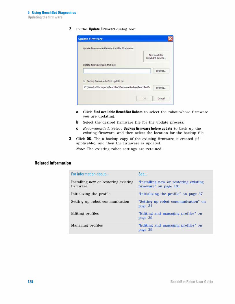
5 Using BenchBot DiagnosticsUpdating the firmware
2 In the Update Firmware dialog box:
a Click Find available BenchBot Robots to select the robot whose firmware you are updating.
b Select the desired firmware file for the update process.
c Recommended. Select Backup firmware before update to back up the existing firmware, and then select the location for the backup file.
3 Click OK. The a backup copy of the existing firmware is created (if applicable), and then the firmware is updated.
Note: The existing robot settings are retained.
Related information
For information about... See...
Installing new or restoring existing firmware
“Installing new or restoring existing firmware” on page 131
Initializing the profile “Initializing the profile” on page 37
Setting up robot communication “Setting up robot communication” on page 31
Editing profiles “Editing and managing profiles” on page 39
Managing profiles “Editing and managing profiles” on page 39
128 BenchBot Robot User Guide
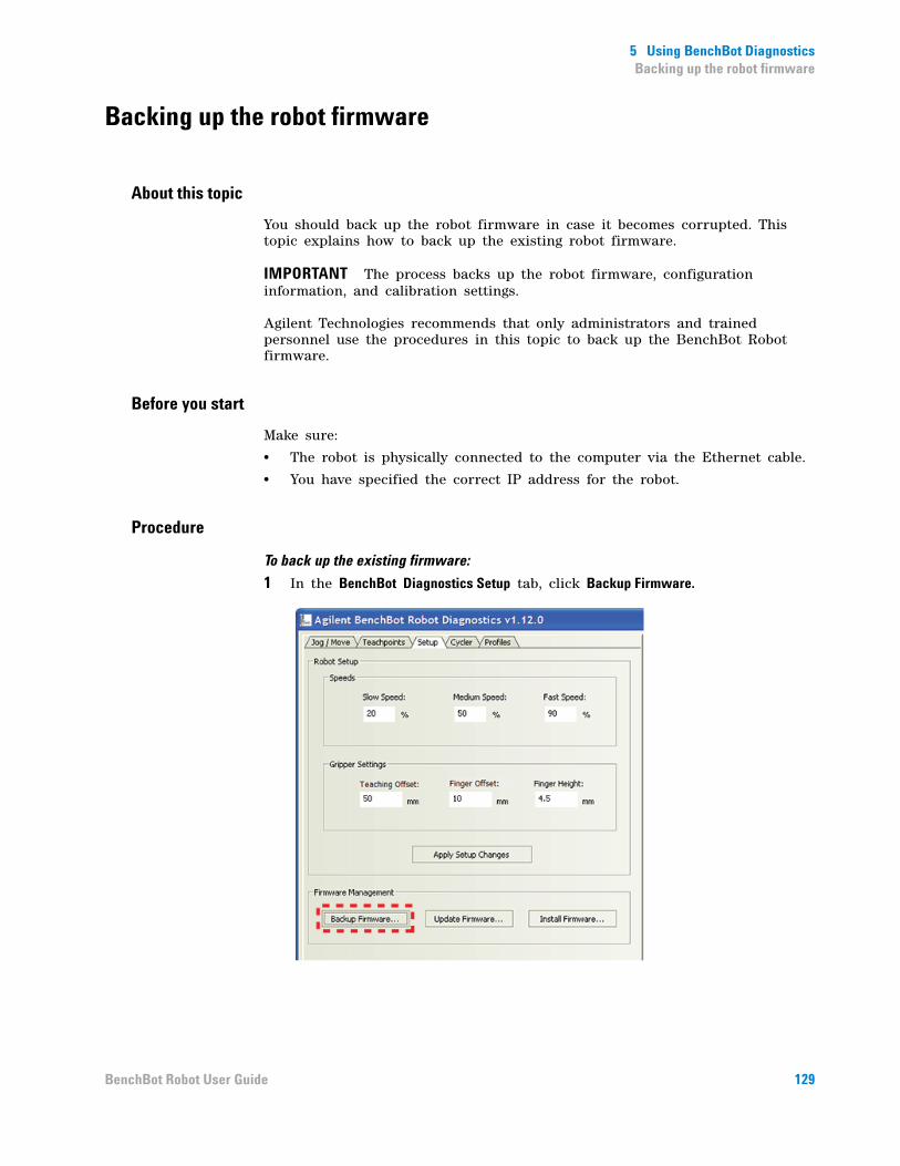
5 Using BenchBot DiagnosticsBacking up the robot firmware
Backing up the robot firmware
About this topic
You should back up the robot firmware in case it becomes corrupted. This topic explains how to back up the existing robot firmware.
IMPORTANT The process backs up the robot firmware, configuration information, and calibration settings.
Agilent Technologies recommends that only administrators and trained personnel use the procedures in this topic to back up the BenchBot Robot firmware.
Before you start
Make sure:
• The robot is physically connected to the computer via the Ethernet cable.
• You have specified the correct IP address for the robot.
Procedure
To back up the existing firmware:
1 In the BenchBot Diagnostics Setup tab, click Backup Firmware.
129BenchBot Robot User Guide
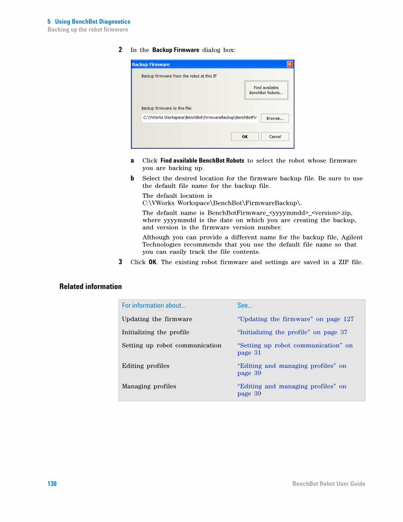
5 Using BenchBot DiagnosticsBacking up the robot firmware
2 In the Backup Firmware dialog box:
a Click Find available BenchBot Robots to select the robot whose firmware you are backing up.
b Select the desired location for the firmware backup file. Be sure to use the default file name for the backup file.
The default location is C:\VWorks Workspace\BenchBot\FirmwareBackup\.
The default name is BenchBotFirmware_<yyyymmdd>_<version>.zip, where yyyymmdd is the date on which you are creating the backup, and version is the firmware version number.
Although you can provide a different name for the backup file, Agilent Technologies recommends that you use the default file name so that you can easily track the file contents.
3 Click OK. The existing robot firmware and settings are saved in a ZIP file.
Related information
For information about... See...
Updating the firmware “Updating the firmware” on page 127
Initializing the profile “Initializing the profile” on page 37
Setting up robot communication “Setting up robot communication” on page 31
Editing profiles “Editing and managing profiles” on page 39
Managing profiles “Editing and managing profiles” on page 39
130 BenchBot Robot User Guide

5 Using BenchBot DiagnosticsInstalling new or restoring existing firmware
Installing new or restoring existing firmware
About this topic
You can use the procedure described in this topic to:
• Install new firmware.
• Restore the existing firmware using a backup copy.
Agilent Technologies recommends that only administrators and trained personnel use the procedures in this topic to restore the BenchBot Robot firmware.
Before you start
Make sure:
• The robot is physically connected to the computer via the Ethernet cable.
• You have specified the correct IP address for the robot.
If you are installing firmware, make sure you back up the current firmware before you proceed to install new firmware. The software will allow you to back up the firmare as you start the installation procedure.
ProcedureTo restore or install the firmware:
1 In the Setup tab, click Install firmware.
CAUTION Installing new firmware overwrites existing robot firmware, configuration information, and calibration settings.
131BenchBot Robot User Guide

5 Using BenchBot DiagnosticsInstalling new or restoring existing firmware
2 In the Install firmware dialog box:
a Click Find available BenchBot Robots to select the robot whose firmware you are installing.
b Select the desired firmware file for the installation process.
c Recommended. Select Backup firmware before update to back up the existing firmware, and then select the location for the backup file.
3 Click OK. Follow the instructions on the screen to install the firmware.
Related information
For information about... See...
Initializing the profile “Initializing the profile” on page 37
Setting up robot communication “Setting up robot communication” on page 31
Editing profiles “Editing and managing profiles” on page 39
Managing profiles “Editing and managing profiles” on page 39
132 BenchBot Robot User Guide
BenchBot Robot User Guide
6Maintaining the robot
This chapter explains how to maintain the BenchBot Robot to optimize performance.
This chapter contains the following topics:
• “Routine maintenance” on page 134
• “Cleaning the robot gripper pads” on page 135
• “Replacing robot gripper pads” on page 137
• “Replacing robot grippers” on page 140
• “Replacing fuses” on page 143
WARNING Only administrators and experienced personnel should perform the procedures in this chapter.
133

6 Maintaining the robotRoutine maintenance
Routine maintenance
Warnings and precautions
Maintenance tasks
For preventive maintenance service, contact Automation Solutions Technical Support.
Related information
WARNING Only administrators and trained personnel should perform the maintenance procedures.
WARNING Always turn off the robot and shut down the system before performing any maintenance procedure. See “Turning on and turning off the robot” on page 21 and the system user documentation.
Task Frequency Procedure
Clean up spills on any part of the robot after a protocol run.
Immediately Use a clean soft cloth to remove the spill.
Inspect gripper pads for dirt, wear, tear, and cracks. Clean the gripper pads. Replace the gripper pads if necessary.
Monthly See one of the following:
• “Cleaning the robot gripper pads” on page 135
• “Replacing robot gripper pads” on page 137
For information about... See...
Shutdown procedure “Turning on and turning off the robot” on page 21
Safety BenchBot Robot Safety and Installation Guide
Replacing robot grippers “Replacing robot grippers” on page 140
Replacing fuses “Replacing fuses” on page 143
Assistance with maintenance procedures
“Reporting problems” on page 165
134 BenchBot Robot User Guide

6 Maintaining the robotCleaning the robot gripper pads
Cleaning the robot gripper pads
About this topic
Dirt on robot gripper pads can cause the robot to drop labware. You should inspect the gripper pads for dirt monthly to ensure optimal performance.
This topic explains how to clean the robot gripper pads.
Material and tools
Make sure you have a soft cloth and access to clean water.
Before you start
Make sure you:
1 Use BenchBot Robot Diagnostics to move the robot to a position where you can easily access the robot grippers.
2 Turn off the robot and the system.
3 Disconnect the power cord from the robot power source.
Procedure
To clean the robot gripper pads:
1 Dampen a soft cloth with water.
2 Gently rub the gripper pads to remove dirt.
3 Make sure the gripper pads are dry before using the system.
WARNING Only administrators and experienced personnel should perform the procedures in this topic.
WARNING Always turn off the robot and shut down the system before performing any maintenance procedure.
WARNING Always disconnect the power cord from the robot before performing any maintenance procedure.
CAUTION Do not use alcohol or alcohol-based cleaning solutions. Alcohol and alcohol-based solutions can damage the gripper pads.
135BenchBot Robot User Guide

6 Maintaining the robotCleaning the robot gripper pads
Related information
For information about... See...
Robot shutdown procedure “Turning on and turning off the robot” on page 21
System shutdown procedure System user documentation
Safety BenchBot Robot Safety and Installation Guide
BenchBot Diagnostics “Using BenchBot Diagnostics” on page 97
136 BenchBot Robot User Guide

6 Maintaining the robotReplacing robot gripper pads
Replacing robot gripper pads
About this topic
Gripper pads can become worn with use. Agilent Technologies recommends that you check the gripper pads monthly and replace them if necessary.
This topic explains how to replace the robot gripper pads.
Materials and tools
Make sure you use the following materials and tools:
• Spare pair of robot gripper pads
• 1.3- mm hex wrench
Before you start
Make sure you:
• Use BenchBot Robot Diagnostics to move the robot to a position where you can easily access the robot grippers.
• Turn off the robot and the system.
• Disconnect the power cord from the robot.
Procedure
To replace a pair of robot gripper pads:
1 Using the 1.3- mm hex wrench, remove the three screws on the pad holders.
WARNING Always turn off the robot and shut down the system before performing any maintenance procedure.
WARNING Always disconnect the power cord from the robot before performing any maintenance procedure.
137BenchBot Robot User Guide

6 Maintaining the robotReplacing robot gripper pads
2 Remove the pad holder from the gripper finger.
3 From the front side of the pad holder, push the pads until they fall from the holder.
4 Place the two new pads on the back side of the pad holder and press forward until they are positioned securely in the gripper finger.
Note: The longer pad should be in the forward slot of the pad holder, and the shorter pad should be in the back slot of the pad holder.
5 Align the pad holder on the inside of the grippers as shown.
6 Insert the three screws in the pad holder, and then use the 1.3- mm hex wrench to tighten the screws.
138 BenchBot Robot User Guide
6 Maintaining the robotReplacing robot gripper pads
Related information
For information about... See...
BenchBot Robot component names “Hardware components” on page 4
Robot shutdown procedure “Turning on and turning off the robot” on page 21
System shutdown procedure System user documentation
Safety BenchBot Robot Safety and Installation Guide
BenchBot Robot Diagnostics “Using BenchBot Diagnostics” on page 97
139BenchBot Robot User Guide
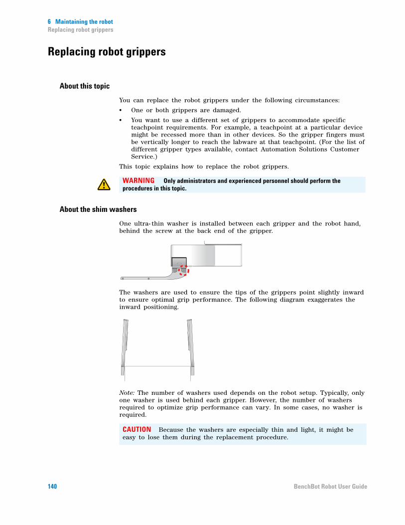
6 Maintaining the robotReplacing robot grippers
Replacing robot grippers
About this topic
You can replace the robot grippers under the following circumstances:
• One or both grippers are damaged.
• You want to use a different set of grippers to accommodate specific teachpoint requirements. For example, a teachpoint at a particular device might be recessed more than in other devices. So the gripper fingers must be vertically longer to reach the labware at that teachpoint. (For the list of different gripper types available, contact Automation Solutions Customer Service.)
This topic explains how to replace the robot grippers.
About the shim washers
One ultra- thin washer is installed between each gripper and the robot hand, behind the screw at the back end of the gripper.
The washers are used to ensure the tips of the grippers point slightly inward to ensure optimal grip performance. The following diagram exaggerates the inward positioning.
Note: The number of washers used depends on the robot setup. Typically, only one washer is used behind each gripper. However, the number of washers required to optimize grip performance can vary. In some cases, no washer is required.
WARNING Only administrators and experienced personnel should perform the procedures in this topic.
CAUTION Because the washers are especially thin and light, it might be easy to lose them during the replacement procedure.
140 BenchBot Robot User Guide
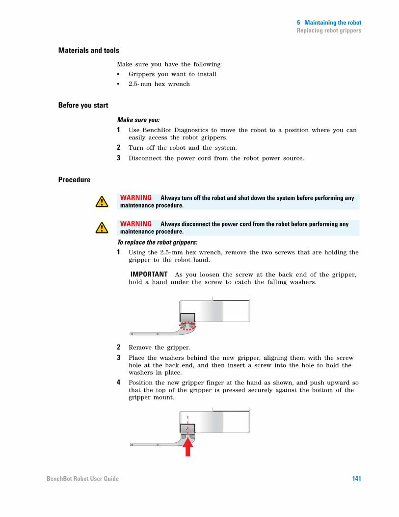
6 Maintaining the robotReplacing robot grippers
Materials and tools
Make sure you have the following:
• Grippers you want to install
• 2.5- mm hex wrench
Before you start
Make sure you:
1 Use BenchBot Diagnostics to move the robot to a position where you can easily access the robot grippers.
2 Turn off the robot and the system.
3 Disconnect the power cord from the robot power source.
Procedure
To replace the robot grippers:
1 Using the 2.5- mm hex wrench, remove the two screws that are holding the gripper to the robot hand.
IMPORTANT As you loosen the screw at the back end of the gripper, hold a hand under the screw to catch the falling washers.
2 Remove the gripper.
3 Place the washers behind the new gripper, aligning them with the screw hole at the back end, and then insert a screw into the hole to hold the washers in place.
4 Position the new gripper finger at the hand as shown, and push upward so that the top of the gripper is pressed securely against the bottom of the gripper mount.
WARNING Always turn off the robot and shut down the system before performing any maintenance procedure.
WARNING Always disconnect the power cord from the robot before performing any maintenance procedure.
141BenchBot Robot User Guide

6 Maintaining the robotReplacing robot grippers
5 While pushing upward on the gripper:
a Tighten the screw at the back end of the gripper.
b Insert and tighten the remaining screw in the gripper.
6 Repeat steps 1 through 5 to replace the second gripper.
Related information
For information about... See...
BenchBot Robot component names “Hardware components” on page 4
Robot shutdown procedure “Turning on and turning off the robot” on page 21
System shutdown procedure System user documentation
Safety BenchBot Robot Safety and Installation Guide
Contacting Automation Solutions Technical Support
“Reporting problems” on page 165
142 BenchBot Robot User Guide

6 Maintaining the robotReplacing fuses
Replacing fuses
About this topic
This topic explains how to replace fuses in the BenchBot Robot.
Fuse location
The BenchBot Robot has two fuses that are located immedately below the AC power entry.
Materials and tools
Make sure you have the following:
• Number 2 flat- head screwdriver
• Replacement fuse(s)
WARNING Only administrators and experienced personnel should perform the procedure in this topic. Alternatively, contact Automation Solutions Technical Support for assistance.
Fuse location Rating
Below AC power entry 6.3 A, 250 V, time- delayed, 5 mm x 20 mm
CAUTION Using an incorrect fuse can damage the robot.
143BenchBot Robot User Guide

6 Maintaining the robotReplacing fuses
Before you start
Make sure you:
• Turn off the robot.
• Turn off the automation system or workstation.
• Disconnect the power cord from the robot.
Procedure
To replace the fuses:
1 At the power inlet, use the flat- head screwdriver to pry open the housing.
2 Carefully pull open the fuse drawer. Two fuses sit in the drawer.
Note: The drawer cannot be removed from the housing.
3 Replace the blown fuse. (A blown fuse has a broken filament.)
4 Slide the fuse cartridge back into the fuse housing.
WARNING Always turn off the robot and shut down the system before performing any maintenance procedure.
WARNING Always disconnect the power cord from the robot power source before performing any maintenance procedure.
144 BenchBot Robot User Guide
6 Maintaining the robotReplacing fuses
5 Press the cartridge securely into the closed position.
6 Plug in the power cable at the power inlet.
Related information
CAUTION A blown fuse can indicate more serious problems. If the new fuse blows after replacement, contact Automation Solutions Technical Support.
For information about... See...
BenchBot Robot component names “Hardware components” on page 4
Robot shutdown procedure “Turning on and turning off the robot” on page 21
System shutdown procedure System user documentation
Safety BenchBot Robot Safety and Installation Guide
Contacting Automation Solutions Technical Support
“Reporting problems” on page 165
145BenchBot Robot User Guide

6 Maintaining the robotReplacing fuses
146 BenchBot Robot User Guide

BenchBot RobotUser Guide
7Troubleshooting robot problems
This chapter explains how to troubleshoot the BenchBot Robot.
This chapter contains the following topics:
• “Recovering from an emergency stop” on page 148
• “Resolving robot initialization errors” on page 150
• “Recovering from servo errors” on page 151
• “Troubleshooting hardware problems” on page 153
• “Troubleshooting error messages” on page 157
• “Reporting problems” on page 165
WARNING Only administrators and experienced personnel should perform the procedures in this chapter.
147
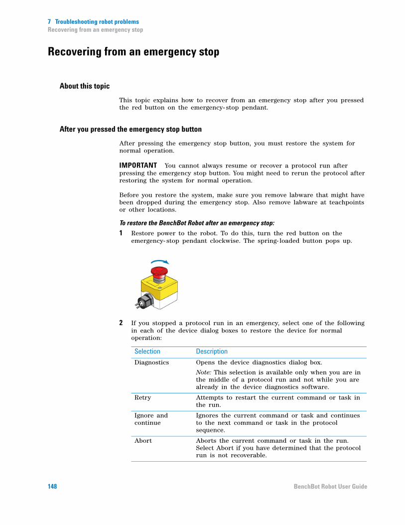
7 Troubleshooting robot problemsRecovering from an emergency stop
Recovering from an emergency stop
About this topic
This topic explains how to recover from an emergency stop after you pressed the red button on the emergency- stop pendant.
After you pressed the emergency stop button
After pressing the emergency stop button, you must restore the system for normal operation.
IMPORTANT You cannot always resume or recover a protocol run after pressing the emergency stop button. You might need to rerun the protocol after restoring the system for normal operation.
Before you restore the system, make sure you remove labware that might have been dropped during the emergency stop. Also remove labware at teachpoints or other locations.
To restore the BenchBot Robot after an emergency stop:
1 Restore power to the robot. To do this, turn the red button on the emergency- stop pendant clockwise. The spring- loaded button pops up.
2 If you stopped a protocol run in an emergency, select one of the following in each of the device dialog boxes to restore the device for normal operation:
Selection Description
Diagnostics Opens the device diagnostics dialog box.
Note: This selection is available only when you are in the middle of a protocol run and not while you are already in the device diagnostics software.
Retry Attempts to restart the current command or task in the run.
Ignore and continue
Ignores the current command or task and continues to the next command or task in the protocol sequence.
Abort Aborts the current command or task in the run. Select Abort if you have determined that the protocol run is not recoverable.
148 BenchBot Robot User Guide

7 Troubleshooting robot problemsRecovering from an emergency stop
3 If there is labware in the BenchBot Robot gripper, release it and move it back to the pickup location. To do this:
a Determine the location from which the labware was picked up.
b In the Robot Error dialog box, click Diagnostics.
c Hold the labware in your hand so that the labware does not drop when you release it from the robot grippers.
d Click Open in the BenchBot Diagnostics Jog/Move tab to release the labware to your hand.
e Place the labware at the pickup location.
4 Click Abort Process in the Stop dialog box.
5 Exit and restart the VWorks software. Communication with the robot is re-established.
Related information
For information about... See...
Pausing and resuming protocol runs
VWorks Automation Control User Guide
Shutting down the system System user documentation
Turning off the robot “Turning on and turning off the robot” on page 21
Using commands in Robot Diagnostics
“Using BenchBot Diagnostics” on page 97
Safety BenchBot Robot Safety and Installation Guide
Reporting problems “Reporting problems” on page 165
149BenchBot Robot User Guide

7 Troubleshooting robot problemsResolving robot initialization errors
Resolving robot initialization errors
About the robot initialization process
Robot initialization occurs:
• When you click Initialize all devices, or when you select the BenchBot Robot and click Initialize selected devices in the device file. The robot homes during the device initialization process.
• When you click Initialize this profile in BenchBot Diagnostics. The robot does not home during the profile initialization process.
During the robot initialization process, the software establishes communication with the robot.
Resolving initialization errors
If a problem occurs during initialization, an error message appears and explains the problem.
To resolve the problem:
1 Make sure the robot is turned on.
2 Make sure the robot cable is connected correctly.
3 Make sure the Ethernet cable is connected correctly.
4 Check the device profile to make sure it is set up correctly for communication.
5 If applicable, follow the instructions in the error message to fix the communication problem.
6 Click Retry to re- initialize the device.
7 If the problem persists, contact Automation Solutions Technical Support.
Related information
For information about... See...
Turning on the robot “Turning on and turning off the robot” on page 21
Editing the profile “Editing and managing profiles” on page 39
Troubleshooting error messages “Troubleshooting error messages” on page 157
Reporting problems “Reporting problems” on page 165
150 BenchBot Robot User Guide

7 Troubleshooting robot problemsRecovering from servo errors
Recovering from servo errors
About this topic
This topic explains how to recover from servo errors.
Causes of servo errors
A servo system controls the robot’s motions. The servo cuts power to the robot if it encounters resistance to movement that is slightly higher than that expected from the inertia of the robotic arm holding a labware. When the power is cut, a servo error is generated.
Most servo errors occur when the labware being carried crashes into another labware that is on a device.
Procedure
To recover from a servo error:
1 Check the system to determine the cause of the collision and remove the obstruction. For example, it might be a labware from a previous run.
2 Check the labware that is held by the robot to make sure it is not damaged and that its contents are not spilled.
3 Make sure the labware did not move in the robot gripper during the collision.
4 If the labware has not moved in the robot gripper and was not damaged during the collision, in the error message dialog box, click one of the following:
Selection Description
Diagnostics Opens the device diagnostics dialog box.
Note: This selection is available only when you are in the middle of a protocol run and not while you are already in the device diagnostics software.
Retry Attempts to restart the current command or task in the run.
Ignore and continue
Ignores the current command or task and continues to the next command or task in the protocol sequence.
Abort Aborts the current command or task in the run. Select Abort if you have determined that the protocol run is not recoverable.
151BenchBot Robot User Guide
7 Troubleshooting robot problemsRecovering from servo errors
5 If the labware has moved during the collision or was damaged, in the error message dialog box, click Diagnostics and move the labware manually:
a Move the robot to a position that is easy for you to access.
b While holding the labware with your hand, click Open in the BenchBot Diagnostics Jog/Move tab to release the labware to your hand. The robot releases the labware.
c Place the labware at the destination location manually.
d Close BenchBot Diagnostics.
e Click in the next error message dialog box, and then click Ignore and continue.
6 If the crash was severe, home the robot.
Related information
For information about... See...
Opening the robot grippers “Opening and closing the robot grippers” on page 122
Homing the robot “Homing the robot and grippers” on page 103
Verifying teachpoints “Verifying teachpoints” on page 71
Reporting problems “Reporting problems” on page 165
152 BenchBot Robot User Guide

7 Troubleshooting robot problemsTroubleshooting hardware problems
Troubleshooting hardware problems
About this topic
This topic lists the following commonly encountered hardware problems, the causes of the problems, and ways to resolve the problems:
• “Communication or power problems” on page 153
• “Gripper, labware, or teachpoint problems” on page 154
• “Homing problems” on page 155
If you are still experiencing problems with the BenchBot Robot after trying the solutions, contact Automation Solutions Technical Support.
Communication or power problems
Problem Cause Solution
The robot does not turn on.
The system electrical requirements are not met.
Make sure the system electrical requirements are met. See the BenchBot Robot Safety and Installation Guide.
The BenchBot Robot is not connected to the power source.
Connect the BenchBot Robot to the power source.
One or more of the robot fuses are blown.
Replace the fuses. See “Replacing fuses” on page 143.
If the fuses are blown immediately after replacement, stop using the robot and contact Automation Solutions Technical Support.
The blue light on the robot shoulder does not turn on after the robot has finished its startup routine.
The robot firmware might be corrupt.
Reload the backup copy of the robot firmware and try again. To reload the backup copy, use the Update firmware button in the BenchBot Diagnostics Setup tab.
The blue LED light is not working. Contact Automation Solutions Technical Support.
153BenchBot Robot User Guide
7 Troubleshooting robot problemsTroubleshooting hardware problems
Gripper, labware, or teachpoint problems
Problem Cause Solution
Labware drops or is held loosely by the robot.
The labware definition for the microplate type might contain incorrect information.
Check the labware definition for errors.
The Grip force is incorrect for the labware.
In Labware Editor, change the Grip torque value for the labware.
The grip range is incorrect. In the Labware Editor and the BenchBot Robot Diagnostics, change the Gripper Offset Range values.
The robot gripper pads are dirty or worn.
Clean or replace the robot gripper pads. See “Cleaning the robot gripper pads” on page 135 or “Replacing robot gripper pads” on page 137.
The gripper- pad holders are loose. Tighten the screws on the gripper-pad holders.
Shim washers are missing or installed incorrectly beneath the screws at the back end of the grippers.
Check and make sure the shim washers are in place. See “About the shim washers” on page 140.
The grippers are damaged. See “Replacing robot grippers” on page 140.
Labware bends when held by the robot.
The Grip force is incorrect for the labware.
In Labware Editor, change the Grip torque value for the labware.
The robot is not moving to and from the teachpoints accurately.
The teachpoint coordinates or orientations are inaccurate. The approach height value might be incorrect.
Verify and edit the teachpoint. See “Verifying teachpoints” on page 71.
The robot axes need to be recalibrated.
Home the robot. See “Homing the robot and grippers” on page 103.
154 BenchBot Robot User Guide

7 Troubleshooting robot problemsTroubleshooting hardware problems
Homing problems
The robot is unable to place labware at the target location accurately.
The target location teachpoint is incorrect.
Verify and edit the teachpoints. See “Verifying teachpoints” on page 71.
The teachpoint of the previously scheduled device is incorrect.
Verify and edit the teachpoints. See “Verifying teachpoints” on page 71.
The target device was moved or reconfigured and the teachpoint was not updated.
Verify and edit the teachpoints. See “Verifying teachpoints” on page 71.
Approach height setting is incorrect.
Check the approach height setting.
The labware might be damaged or deformed.
Replace the damaged or deformed labware.
The robot gripper pads are dirty or worn.
Clean or replace the robot gripper pads. See “Cleaning the robot gripper pads” on page 135 or “Replacing robot gripper pads” on page 137.
The robot grippers are damaged. Contact Automation Solutions Technical Support to replace the robot grippers.
Incorrect gripper offset range is specified.
Check and correct the gripper offset ranges for the labware, the pick location, and the place location. See “Setting the Min and Max Gripper Offset parameters” on page 65.
The robot placed the labware such that the A1 well is in the wrong orientation.
The incorrect A1- well orientation is specified for the teachpoint.
In the teachpoint file, verify the A1-well orientation specification. Change the specification if necessary. See “Specifying the A1- well orientation” on page 57.
The robot collides with devices or obstacles when moving from teachpoint to teachpoint.
The incorrect robot- arm orientation, approach height, or approach distance values are used.
In the teachpoint file, check and correct the robot- arm orientation, approach height value, and approach distance value. See “Setting teachpoints” on page 41.
Problem Cause Solution
Problem Cause Solution
The robot does not home.
An obstacle is preventing the robot from homing.
Remove the obstacle and try again.
The robot grippers are holding labware.
Remove the labware and try again.
155BenchBot Robot User Guide
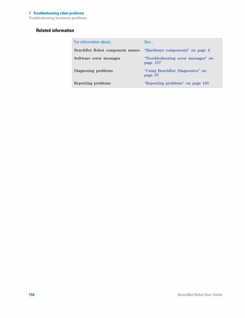
7 Troubleshooting robot problemsTroubleshooting hardware problems
Related information
For information about... See...
BenchBot Robot component names “Hardware components” on page 4
Software error messages “Troubleshooting error messages” on page 157
Diagnosing problems “Using BenchBot Diagnostics” on page 97
Reporting problems “Reporting problems” on page 165
156 BenchBot Robot User Guide

7 Troubleshooting robot problemsTroubleshooting error messages
Troubleshooting error messages
The following table lists commonly encountered error messages, the causes of the errors, and ways to resolve the errors. The error messages are listed by error message ID, which is displayed on the title bar of the error message dialog box.
If you are still experiencing problems with the robot after trying the solutions, or if an error not on the list is displayed, contact Automation Solutions Technical Support.
For protocol- related errors, see the VWorks Automation Control User Guide.
ID Error message Cause Solution
101 Invalid jog destination You have specified a jog increment that will cause the robot to move outside of its limits.
Reduce the jog increment so that the robot can reach its destination.
102 Plate in gripper The robot is trying to home, but it has a labware in its grippers.
Remove the labware from the robot grippers and try homing again.
104 Failed to grip The robot is expecting labware in its grippers.
Place a plate in the robot grippers.
105 Gripping an item outside the gripping tolerance
The robot is holding labware that is either too small or too large.
Check that the correct labware is in the grippers. Alternatively, check and correct the parameter settings in the Labware Editor.
109 Wrist wound The wrist is rotated beyond its permitted limits.
In the error message dialog box, select Yes to unwind and home the wrist joint.
801 A destination and next location must be specified
In a lidding or relidding operation, the lid device and the next teachpoint must be specified.
Check the protocol and make sure the lid device is specified correctly. Check that the teachpoint after the lidding task is also specified correctly.
802 A source and/or destination must be specified
You are attempting to transfer labware, but you have not selected the source or destination teachpoints.
Select the source and destination teachpoints.
803 Approach distance cannot be less than zero
You have specified a negative value for the Approach Distance parameter.
Change the Approach Distance value so that it is 0 or greater.
157BenchBot Robot User Guide
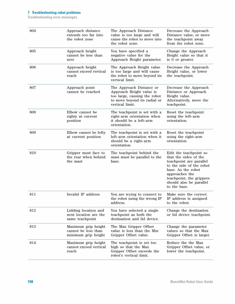
7 Troubleshooting robot problemsTroubleshooting error messages
804 Approach distance extends too far into the robot zone
The Approach Distance value is too large and will cause the robot to move into the robot zone.
Decrease the Approach Distance value, or move the teachpoint away from the robot zone.
805 Approach height cannot be less than zero
You have specified a negative value for the Approach Height parameter.
Change the Approach Height value so that it is 0 or greater.
806 Approach height cannot exceed vertical reach
The Approach Height value is too large and will cause the robot to move beyond its vertical limit.
Decrease the Approach Height value, or lower the teachpoint.
807 Approach point cannot be reached
The Approach Distance or Approach Height value is too large, causing the robot to move beyond its radial or vertical limit.
Decrease the Approach Distance or Approach Height value. Alternatively, move the teachpoint.
808 Elbow cannot be righty at current position
The teachpoint is set with a right- arm orientation when it should be a left- arm orientation.
Reset the teachpoint using the left- arm orientation.
809 Elbow cannot be lefty at current position
The teachpoint is set with a left- arm orientation when it should be a right- arm orientation.
Reset the teachpoint using the right- arm orientation.
810 Gripper must face to the rear when behind the mast
The teachpoint behind the mast must be parallel to the base.
Edit the teachpoint so that the sides of the teachpoint are parallel to the side of the robot base. As the robot approaches the teachpoint, the grippers should also be parallel to the base.
811 Invalid IP address You are trying to connect to the robot using the wrong IP address.
Make sure the correct IP address is assigned to the robot.
812 Lidding location and next location are the same teachpoint
You have selected a single teachpoint as both the destination and lid device.
Change the destination or lid device teachpoint.
813 Maximum grip height cannot be less than minimum grip height
The Max Gripper Offset value is less than the Min Gripper Offset value.
Change the parameter values so that the Max Gripper Offset is larger.
814 Maximum grip height cannot exceed vertical reach
The teachpoint is set too high so that the Max Gripper Offset exceeds the robot’s vertical limit.
Reduce the the Max Gripper Offset value, or lower the teachpoint.
158 BenchBot Robot User Guide
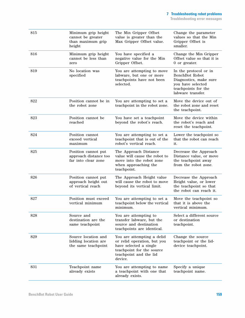
7 Troubleshooting robot problemsTroubleshooting error messages
815 Minimum grip height cannot be greater than maximum grip height
The Min Gripper Offset value is greater than the Max Gripper Offset value.
Change the parameter values so that the Min Gripper Offset is smaller.
816 Minimum grip height cannot be less than zero
You have specified a negative value for the Min Gripper Offset.
Change the Min Gripper Offset value so that it is 0 or greater.
819 No location was specified
You are attempting to move labware, but one or more teachpoints have not been selected.
In the protocol or in BenchBot Robot Diagnostics, make sure you have selected teachpoints for the labware transfer.
822 Position cannot be in the robot zone
You are attempting to set a teachpoint in the robot zone.
Move the device out of the robot zone and reset the teachpoint.
823 Position cannot be reached
You have set a teachpoint beyond the robot’s reach.
Move the device within the robot’s reach and reset the teachpoint.
824 Position cannot exceed vertical maximum
You are attempting to set a teachpoint that is out of the robot’s vertical reach.
Lower the teachpoint so that the robot can reach it.
825 Position cannot put approach distance too far into clear zone
The Approach Distance value will cause the robot to move into the robot zone when approaching the teachpoint.
Decrease the Approach Distance value, or move the teachpoint away from the robot zone.
826 Position cannot put approach height out of vertical reach
The Approach Height value will cause the robot to move beyond its vertical limit.
Decrease the Approach Height value, or lower the teachpoint so that the robot can reach it.
827 Position must exceed vertical minimum
You are attempting to set a teachpoint below the vertical minimum.
Move the teachpoint so that it is above the vertical minimum.
828 Source and destination are the same teachpoint
You are attempting to transfer labware, but the source and destination teachpoints are identical.
Select a different source or destination teachpoint.
829 Source location and lidding location are the same teachpoint
You are attempting a delid or relid operation, but you have selected a single teachpoint for the source teachpoint and the lid device.
Change the source teachpoint or the lid-device teachpoint.
831 Teachpoint name already exists
You are attempting to name a teachpoint with one that already exists.
Specify a unique teachpoint name.
159BenchBot Robot User Guide

7 Troubleshooting robot problemsTroubleshooting error messages
833 Yaw angle cannot be less than - 180
The angle you specified is less than –180°. Yaw must be between - 180° and 180°.
Change the Yaw so that it is between - 180° and 180. For example, you should specify - 190° as 170°. (- 190° + 360° = 170°).
834 Yaw angle cannot be greater than 180°
The angle you specified is greater than 180°. Yaw must be between - 180° and 180°.
Change the Yaw so that it is between - 180° and 180. For example, you should specify 190° as –170°. (190° – 360° = –170°).
852 No labware is currently gripped to place at the destination
The robot is attempting a place- to operation but it does not have labware in its grippers.
Place labware in the robot grippers and try again.
853 Unspecified destination location could not be created
A destination teachpoint was not specified.
Select a destination teachpoint.
854 The source location has no approach that is compatible with the specified labware
The source teachpoint gripper offset range specified in BenchBot Robot Diagnostics does not overlap with the gripper offset range in the Labware Editor.
Change the gripper offset ranges in BenchBot Robot Diagnostics and in the Labware Editor so that they overlap.
855 The destination location has no approach that is compatible with the specified labware
The destination teachpoint gripper offset range specified in BenchBot Robot Diagnostics does not overlap with the gripper offset range in the Labware Editor.
Change the gripper offset ranges in BenchBot Robot Diagnostics and in the Labware Editor so that they overlap.
856 A valid combination of the specified source location and approaches could not be found
The source teachpoint gripper offset range specified in BenchBot Robot Diagnostics does not overlap with the gripper offset range in the Labware Editor.
Change the gripper offset ranges in BenchBot Robot Diagnostics and in the Labware Editor so that they overlap.
857 A valid combination of the specified destination location and approaches could not be found
The destination teachpoint gripper offset range specified in BenchBot Robot Diagnostics does not overlap with the gripper offset range in the Labware Editor.
Change the gripper offset ranges in BenchBot Robot Diagnostics and in the Labware Editor so that they overlap.
160 BenchBot Robot User Guide

7 Troubleshooting robot problemsTroubleshooting error messages
858 A path between source and destination locations could not be found
A regrip station is expected, because:
• The labware orientations of the two teachpoints do not match.
• The gripper offset ranges of the two teachpoints do not match.
Add a regrip station. Alternatively, change the labware orientation, or change the gripper offset ranges so that they match.
859 A path to the next location could not be found
A regrip station is expected, because:
• The labware orientations of the source and destination teachpoints do not match.
• The gripper offset ranges of the two teachpoints do not match.
Add a regrip station. Alternatively, change the labware orientation, or change the gripper offset ranges so that they match.
871 Not connected to BenchBot
The robot is disconnected from the computer.
Try one or more of the following:
• Check the Ethernet connection between the robot and the computer.
• Make sure you have selected the correct profile, and then initialize the robot.
873 Command timed out An obstacle is preventing the robot from carrying out a comand.
Remove obstacles from the robot’s path. Make sure there is no labware in the robot grippers.
876 A path to the destination location could not be found from the source location
A regrip station is expected, because:
• The labware orientations of the source and destination teachpoints do not match.
• The gripper offset ranges of the two teachpoints do not match.
Add a regrip station. Alternatively, change the labware orientation, or change the gripper offset ranges so that they match.
877 The path contains an illegal move
A regrip station is expected, because:
• The labware orientations of the source and destination teachpoints do not match.
• The gripper offset ranges of the two teachpoints do not match.
Add a regrip station. Alternatively, change the labware orientation, or change the gripper offset ranges so that they match.
161BenchBot Robot User Guide

7 Troubleshooting robot problemsTroubleshooting error messages
878 The path contains an illegal offset regrip move
You are transferring labware, but the gripper offset ranges of the two teachpoints and the regrip station do not overlap.
Make sure the gripper offset ranges of the three locations overlap.
879 The path contains an illegal orientation regrip move
You are transfering labware, but the gripper offset ranges of the two teachpoints and the regrip station do not overlap.
Make sure the gripper offset ranges of the three locations overlap.
886 Unexpectedly gripping labware while trying to pick
The robot is attempting to pick up a labware, but it is already holding labware in its grippers.
Remove the labware from the robot grippers and try the pick- up operation again.
887 Gripping unknown plate while trying to place
The robot is expecting the labware to be in a certain orientation, but the labware is not held in that orientation. For example, the robot is expecting a landscape orientation, but the labware is in the portrait orientation.
Make sure the labware is held in the correct orientation. Check the labware orientation for the source and destination teachpoints.
The labware is held crookedly.
Remove the labware from the robot and try again. If the problem persists, check and correct the parameters in the Labware Editor.
888 Failed to pick up labware
The robot is attempting to pick up labware from the designated teachpoint. The labware is missing, or the incorrect labware is at that teachpoint.
Make sure the correct labware is present at the teachpoint.
889 Failed to regrip labware
The robot is attempting to regrip labware at the regrip station. The labware is missing, or the incorrect labware is at that station.
Make sure the correct labware is present at the regrip station.
1012 Joint out of range You are attempting to jog the robot beyond its limits.
Reduce the jog increment so that the robot moves within its range.
1014 Time out during nulling
An obstacle is preventing the robot from carrying out a comand.
Remove obstacles from the robot’s path. Make sure there is no labware in the robot grippers.
162 BenchBot Robot User Guide
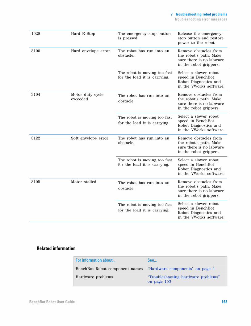
7 Troubleshooting robot problemsTroubleshooting error messages
Related information
1028 Hard E- Stop The emergency- stop button is pressed.
Release the emergency-stop button and restore power to the robot.
3100 Hard envelope error The robot has run into an obstacle.
Remove obstacles from the robot’s path. Make sure there is no labware in the robot grippers.
The robot is moving too fast for the load it is carrying.
Select a slower robot speed in BenchBot Robot Diagnostics and in the VWorks software.
3104 Motor duty cycle exceeded
The robot has run into an obstacle.
Remove obstacles from the robot’s path. Make sure there is no labware in the robot grippers.
The robot is moving too fast for the load it is carrying.
Select a slower robot speed in BenchBot Robot Diagnostics and in the VWorks software.
3122 Soft envelope error The robot has run into an obstacle.
Remove obstacles from the robot’s path. Make sure there is no labware in the robot grippers.
The robot is moving too fast for the load it is carrying.
Select a slower robot speed in BenchBot Robot Diagnostics and in the VWorks software.
3105 Motor stalled The robot has run into an obstacle.
Remove obstacles from the robot’s path. Make sure there is no labware in the robot grippers.
The robot is moving too fast for the load it is carrying.
Select a slower robot speed in BenchBot Robot Diagnostics and in the VWorks software.
For information about... See...
BenchBot Robot component names “Hardware components” on page 4
Hardware problems “Troubleshooting hardware problems” on page 153
163BenchBot Robot User Guide

7 Troubleshooting robot problemsTroubleshooting error messages
Recovering from emergency stops “Recovering from an emergency stop” on page 148
Recovering from servo errors “Recovering from servo errors” on page 151
Setting and editing teachpoints “Teachpoint setting workflow” on page 42
Changing the gripper offset range “Setting the Min and Max Gripper Offset parameters” on page 65
Changing the approach distance and approach height
“Setting the Approach Height and Approach Distance parameters” on page 61
Setting robot- arm orientation “Planning BenchBot Robot teachpoints” on page 44
Safety BenchBot Robot Safety and Installation Guide
Reporting problems to Agilent Technologies
“Reporting problems” on page 165
For information about... See...
164 BenchBot Robot User Guide

7 Troubleshooting robot problemsReporting problems
Reporting problems
Contacting Automation Solutions Technical Support
If you find a problem with the BenchBot Robot, contact Automation Solutions Technical Support at one of the following:
Europe
Phone: +44 (0)1763850230
email: [email protected]
US and rest of world
Phone: 1.800.979.4811 (US only) or +1.408.345.8011
email: [email protected]
Reporting hardware problems
When contacting Agilent Technologies, make sure you have the serial number of the device ready.
Figure BenchBot Robot serial number label location
Reporting software problems
When you contact Automation Solutions Technical Support, make sure you provide the following:
• Short description of the problem
• Relevant software version number (for example, automation control software, diagnostics software, ActiveX control software, and firmware)
• Error message text (or screen capture of the error message dialog box)
• Relevant files, such as log files
165BenchBot Robot User Guide

7 Troubleshooting robot problemsReporting problems
Reporting user guide problems
If you find a problem with this user guide or have suggestions for improvement, send your comments in an email to [email protected].
Related information
For information about... See...
Hardware problems “Troubleshooting hardware problems” on page 153
Software error messages “Troubleshooting error messages” on page 157
Recovering from emergency stops “Recovering from an emergency stop” on page 148
Recovering from initialization errors
“Resolving robot initialization errors” on page 150
Recovering from servo errors “Recovering from servo errors” on page 151
Safety BenchBot Robot Safety and Installation Guide
166 BenchBot Robot User Guide
BenchBot RobotUser Guide
A
Quick reference
This appendix provides a quick reference of menu commands, selections, options, and status information in the BenchBot Diagnostics dialog box. The topics are:
• “Robot status area” on page 168
• “Log area” on page 170
• “General commands” on page 171
• “Jog/Move tab” on page 172
• “Teachpoints tab” on page 177
• “Cycler tab” on page 180
• “Setup tab” on page 181
• “Profiles tab” on page 184
167
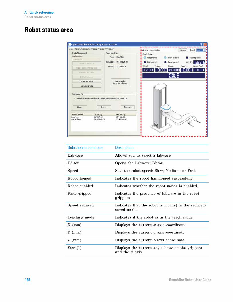
A Quick referenceRobot status area
Robot status area
Selection or command Description
Labware Allows you to select a labware.
Editor Opens the Labware Editor.
Speed Sets the robot speed: Slow, Medium, or Fast.
Robot homed Indicates the robot has homed successfully.
Robot enabled Indicates whether the robot motor is enabled.
Plate gripped Indicates the presence of labware in the robot grippers.
Speed reduced Indicates that the robot is moving in the reduced-speed mode.
Teaching mode Indicates if the robot is in the teach mode.
X (mm) Displays the current x- axis coordinate.
Y (mm) Displays the current y- axis coordinate.
Z (mm) Displays the current z- axis coordinate.
Yaw (°) Displays the current angle between the grippers and the x- axis.
168 BenchBot Robot User Guide
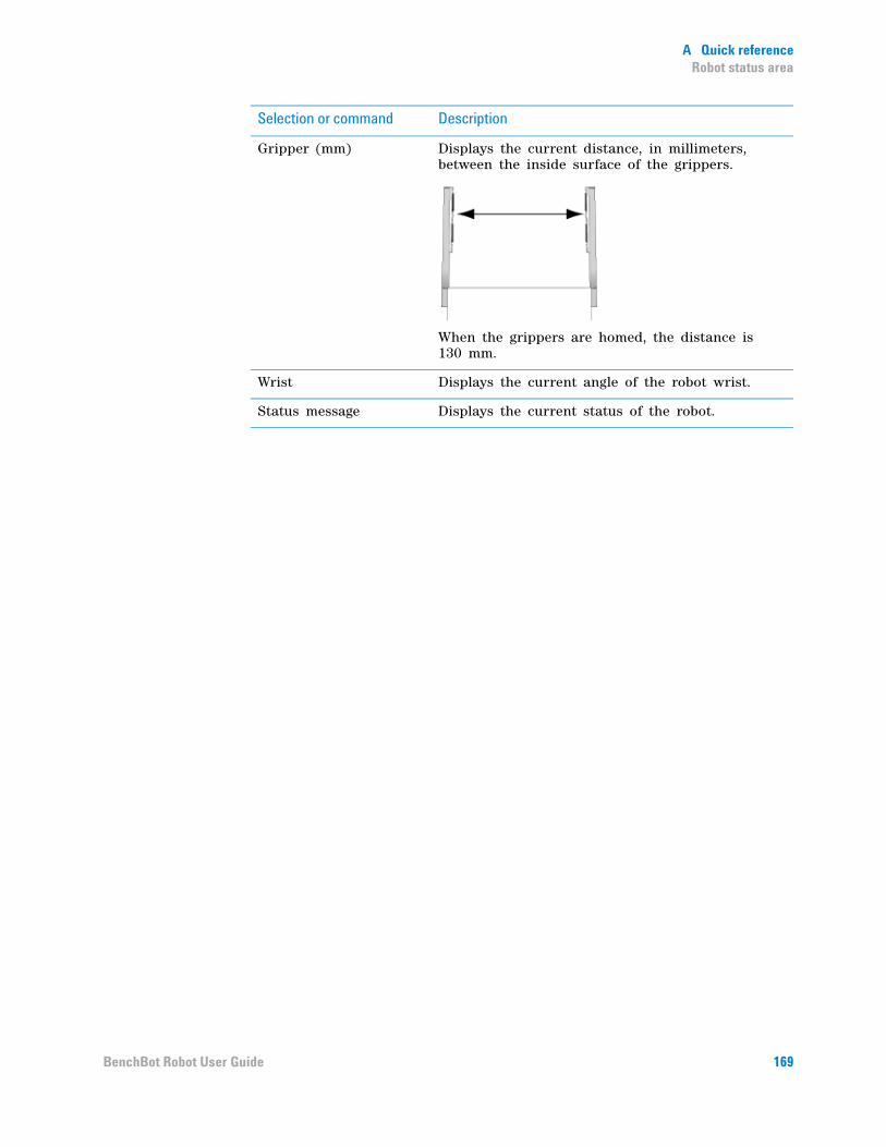
A Quick referenceRobot status area
Gripper (mm) Displays the current distance, in millimeters, between the inside surface of the grippers.
When the grippers are homed, the distance is 130 mm.
Wrist Displays the current angle of the robot wrist.
Status message Displays the current status of the robot.
Selection or command Description
169BenchBot Robot User Guide
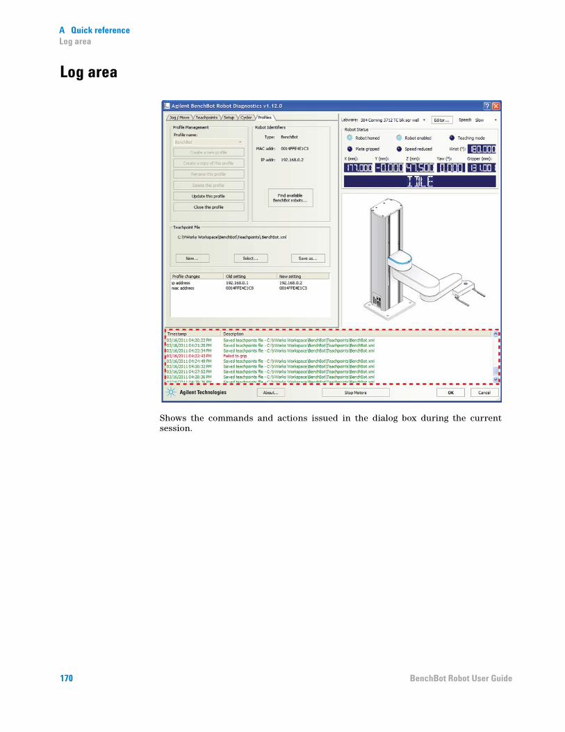
A Quick referenceLog area
Log area
Shows the commands and actions issued in the dialog box during the current session.
170 BenchBot Robot User Guide
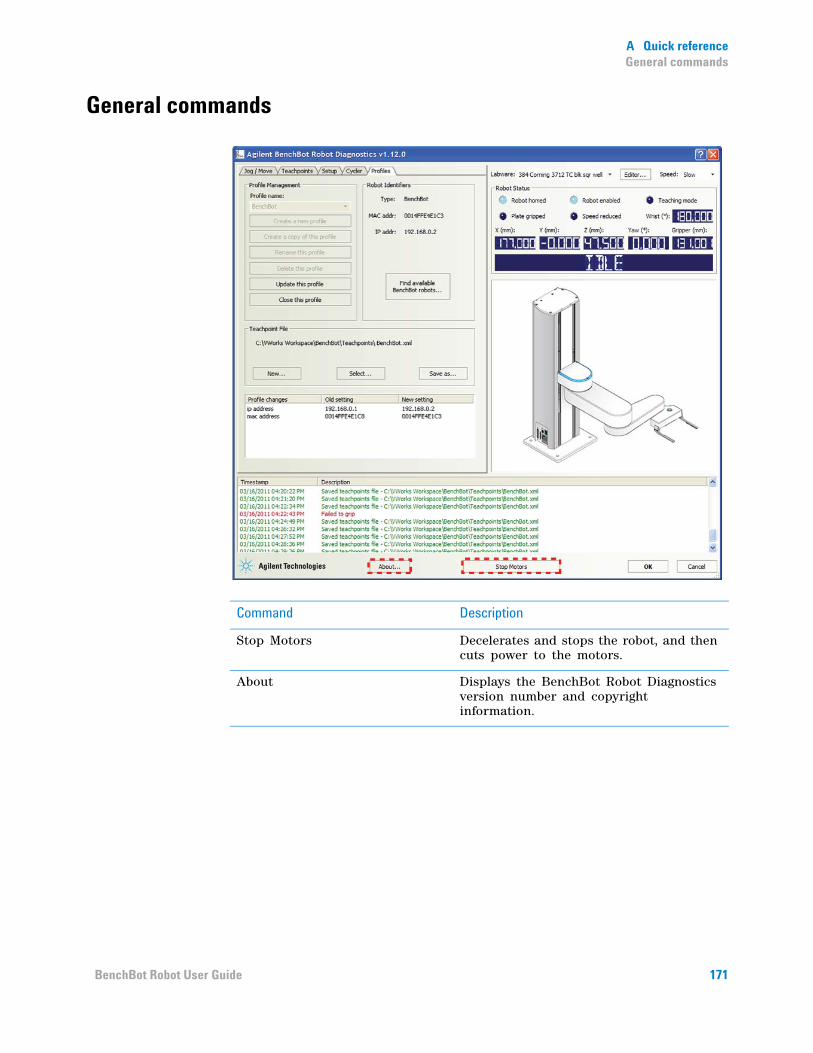
A Quick referenceGeneral commands
General commands
Command Description
Stop Motors Decelerates and stops the robot, and then cuts power to the motors.
About Displays the BenchBot Robot Diagnostics version number and copyright information.
171BenchBot Robot User Guide
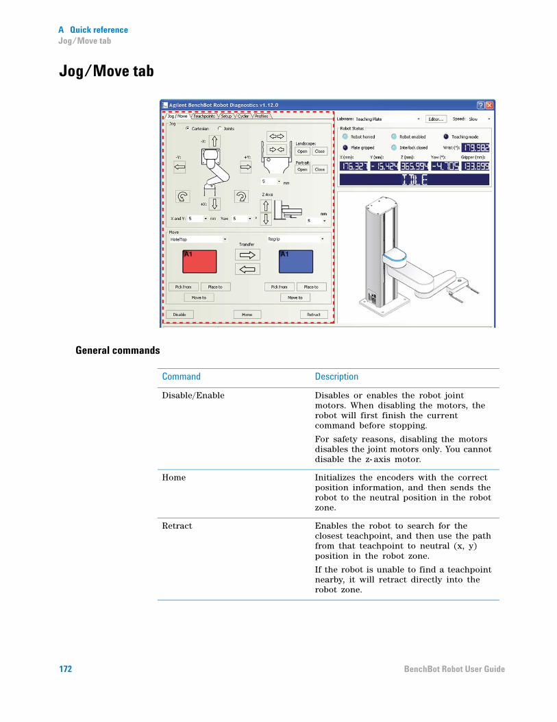
A Quick referenceJog/Move tab
Jog/Move tab
General commands
Command Description
Disable/Enable Disables or enables the robot joint motors. When disabling the motors, the robot will first finish the current command before stopping.
For safety reasons, disabling the motors disables the joint motors only. You cannot disable the z- axis motor.
Home Initializes the encoders with the correct position information, and then sends the robot to the neutral position in the robot zone.
Retract Enables the robot to search for the closest teachpoint, and then use the path from that teachpoint to neutral (x, y) position in the robot zone.
If the robot is unable to find a teachpoint nearby, it will retract directly into the robot zone.
172 BenchBot Robot User Guide

A Quick referenceJog/Move tab
Jog area: Tool space commands and parameters
Command or parameter Description
Tool Displays the jog buttons to move the labware to a target Tool coordinate (x, y, yaw).
In Tool space, all movements are measured with respect to the center of the labware.
Tool space jog buttons:
X:
Y:
Yaw:
Jogs the robot in the specified direction by the specified distance in millimeters or by the specified angle in degrees.
X and Y jog increment Specifies the distance, in millimeters, the robot moves when you click an x- or y-axis jog button.
Yaw jog increment Specifies the angle, in degrees, the labware rotates when you click a rotating jog button.
173BenchBot Robot User Guide
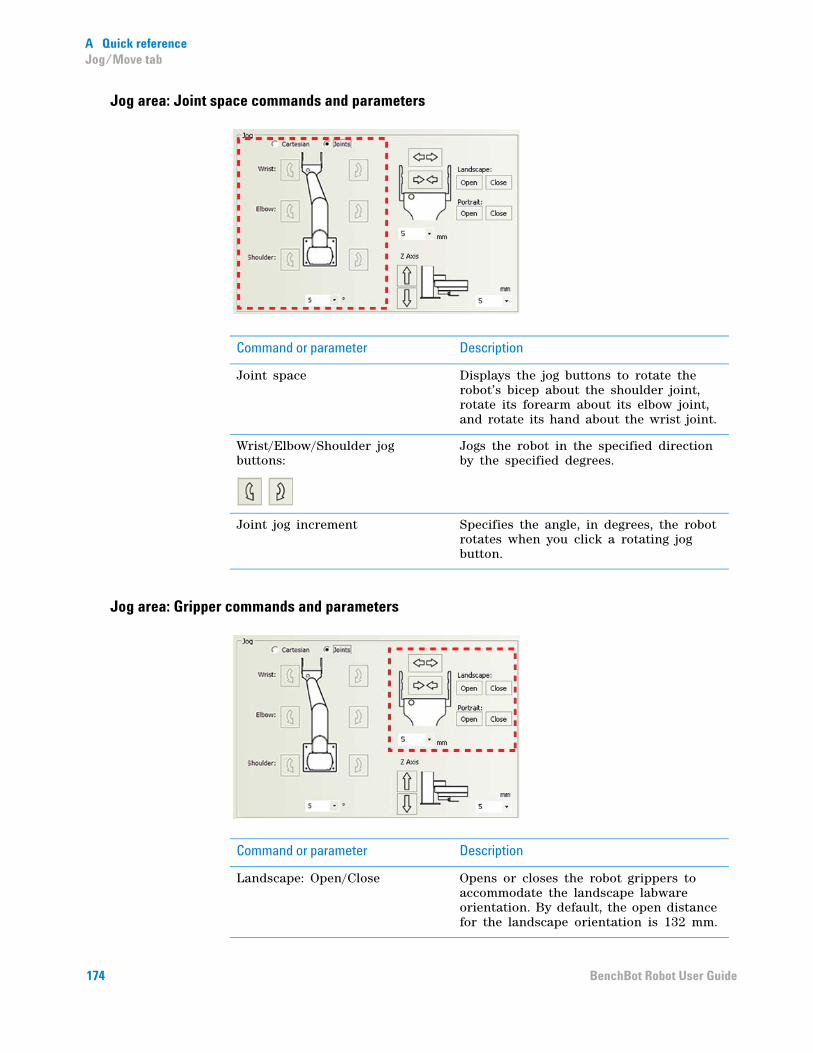
A Quick referenceJog/Move tab
Jog area: Joint space commands and parameters
Jog area: Gripper commands and parameters
Command or parameter Description
Joint space Displays the jog buttons to rotate the robot’s bicep about the shoulder joint, rotate its forearm about its elbow joint, and rotate its hand about the wrist joint.
Wrist/Elbow/Shoulder jog buttons:
Jogs the robot in the specified direction by the specified degrees.
Joint jog increment Specifies the angle, in degrees, the robot rotates when you click a rotating jog button.
Command or parameter Description
Landscape: Open/Close Opens or closes the robot grippers to accommodate the landscape labware orientation. By default, the open distance for the landscape orientation is 132 mm.
174 BenchBot Robot User Guide
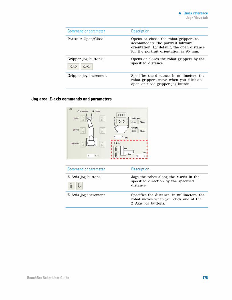
A Quick referenceJog/Move tab
Jog area: Z-axis commands and parameters
Portrait: Open/Close Opens or closes the robot grippers to accommodate the portrait labware orientation. By default, the open distance for the portrait orientation is 95 mm.
Gripper jog buttons:
Opens or closes the robot grippers by the specified distance.
Gripper jog increment Specifies the distance, in millimeters, the robot grippers move when you click an open or close gripper jog button.
Command or parameter Description
Command or parameter Description
Z Axis jog buttons:
Jogs the robot along the z- axis in the specified direction by the specified distance.
Z Axis jog increment Specifies the distance, in millimeters, the robot moves when you click one of the Z Axis jog buttons.
175BenchBot Robot User Guide
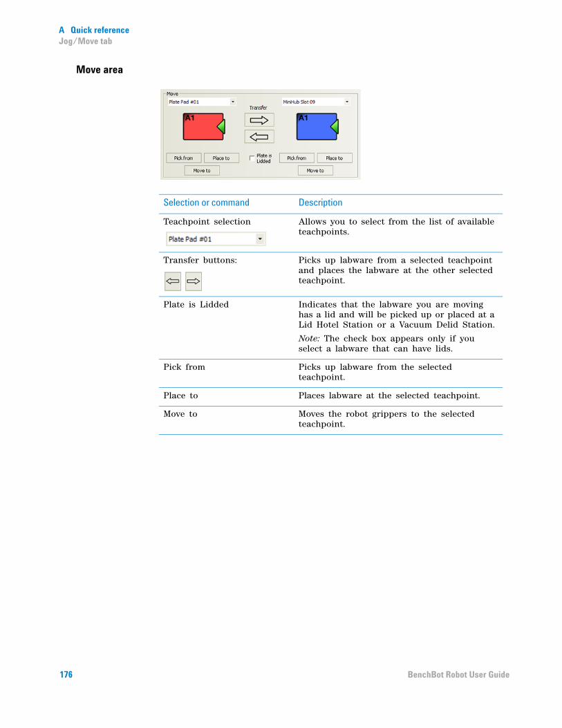
A Quick referenceJog/Move tab
Move area
Selection or command Description
Teachpoint selection Allows you to select from the list of available teachpoints.
Transfer buttons:
Picks up labware from a selected teachpoint and places the labware at the other selected teachpoint.
Plate is Lidded Indicates that the labware you are moving has a lid and will be picked up or placed at a Lid Hotel Station or a Vacuum Delid Station.
Note: The check box appears only if you select a labware that can have lids.
Pick from Picks up labware from the selected teachpoint.
Place to Places labware at the selected teachpoint.
Move to Moves the robot grippers to the selected teachpoint.
176 BenchBot Robot User Guide

A Quick referenceTeachpoints tab
Teachpoints tab
Commands
Teachpoints table
Command Description
Enter teach mode Enables you to move the robot arm and hand freely without resistance.
/ (Maximize/Minimize) Displays all of the columns or displays the first few columns in the teachpoints table.
New teachpoint Adds a new teachpoint in the table.
Delete selections Deletes the selected teachpoints.
Save teachpoints Saves the changes made to the teachpoints.
Column name Description
Name The name of the teachpoint. To change the name, double- click the box and type the new name.
177BenchBot Robot User Guide
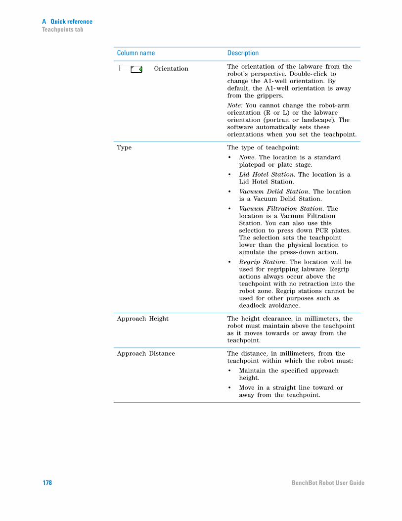
A Quick referenceTeachpoints tab
Orientation The orientation of the labware from the robot’s perspective. Double- click to change the A1- well orientation. By default, the A1- well orientation is away from the grippers.
Note: You cannot change the robot- arm orientation (R or L) or the labware orientation (portrait or landscape). The software automatically sets these orientations when you set the teachpoint.
Type The type of teachpoint:
• None. The location is a standard platepad or plate stage.
• Lid Hotel Station. The location is a Lid Hotel Station.
• Vacuum Delid Station. The location is a Vacuum Delid Station.
• Vacuum Filtration Station. The location is a Vacuum Filtration Station. You can also use this selection to press down PCR plates. The selection sets the teachpoint lower than the physical location to simulate the press- down action.
• Regrip Station. The location will be used for regripping labware. Regrip actions always occur above the teachpoint with no retraction into the robot zone. Regrip stations cannot be used for other purposes such as deadlock avoidance.
Approach Height The height clearance, in millimeters, the robot must maintain above the teachpoint as it moves towards or away from the teachpoint.
Approach Distance The distance, in millimeters, from the teachpoint within which the robot must:
• Maintain the specified approach height.
• Move in a straight line toward or away from the teachpoint.
Column name Description
178 BenchBot Robot User Guide

A Quick referenceTeachpoints tab
Min Gripper Offset The vertical distance, in millimeters, from the teachpoint to the lowest point where the grippers will hold the labware at the teachpoint. The default value is 0 mm.
This value is used with the Maximum gripper offset value to define a range within which the grippers can hold the labware at the teachpoint location.
IMPORTANT During the run, the VWorks software checks the gripper offset range defined in this tab and the range in the labware’s definition.
IMPORTANT For regrip stations, make sure the range can accommodate all labware.
Max Gripper Offset The vertical distance, in millimeters, from the teachpoint to the highest point where the grippers will hold the labware at the teachpoint. The default value is 10 mm.
This value is used with the Minimum gripper offset value to define a range within which the grippers can hold the labware at the teachpoint location.
X The current x- axis coordinate value, in millimeters.
Y The current y- axis coordinate value, in millimeters.
Z The current z- axis coordinate value, in millimeters.
Yaw The angle between the grippers and the x- axis.
Bend The robot- arm orientation. Possible orientations are L (left) or R (right). The orientation is determined when you set the teachpoint and cannot be changed in this tab.
Last Modified The timestamp that shows when a teachpoint was changed.
Column name Description
179BenchBot Robot User Guide

A Quick referenceCycler tab
Cycler tab
Command or option Description
Add teachpoints Allows you to select the desired teachpoints from the existing teachpoints list.
Remove teachpoints Removes the selected teachpoints from the Teachpoints list.
Pause after ___ cycles Pauses the cycling after the specified number of cycle times.
All permutations Runs the all- permutations cycling sequence.
Start Starts or pauses the cycling.
Stop Stops the cycling. The robot will stop after the current pick- and- place action.
Cycle count Displays the number of completed cycles.
180 BenchBot Robot User Guide

A Quick referenceSetup tab
Setup tab
Speeds
The following robot speeds are definable as a percentage of the factory- set maximum speed. The default percentage settings are as follows:
Speed Default
Slow 20%
Medium 50%
Fast 90%
181BenchBot Robot User Guide

A Quick referenceSetup tab
Gripper Settings (mm)
Command or option Description
Teaching Offset The distance, in millimeters, between the bottom of the teaching plate and the bottom of the grippers. The default is 10 mm.
Finger Offset The distance, in millimeters, between the bottom of the grippers and the bottom of its mounting base. The default is 16 mm.
Finger Height The height, in millimeters, of the grippers. This information is used when the robot is handling lidded labware. The default is 4.2 mm.
182 BenchBot Robot User Guide
A Quick referenceSetup tab
Commands
Firmware Management
Command or option Description
Apply Setup Changes The command that applies and saves the current parameter settings to the robot.
Speed Default
Back up firmware Backs up the firmware to a .zip file.
Update firmware Backs up the existing firmware (if specified), and then updates the firmware. Note that the update action does not overwrite the existing robot configuration information or calibration settings.
Install firmware Backs up the existing firmware (if specified), and then installs the firmware from a selected file. The installation overwrites the existing firmware, configuration information, and calibration settings.
183BenchBot Robot User Guide
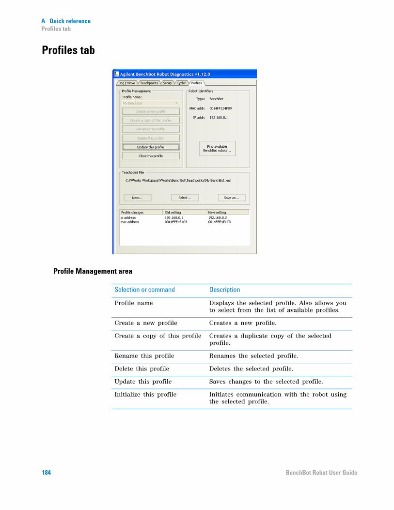
A Quick referenceProfiles tab
Profiles tab
Profile Management area
Selection or command Description
Profile name Displays the selected profile. Also allows you to select from the list of available profiles.
Create a new profile Creates a new profile.
Create a copy of this profile Creates a duplicate copy of the selected profile.
Rename this profile Renames the selected profile.
Delete this profile Deletes the selected profile.
Update this profile Saves changes to the selected profile.
Initialize this profile Initiates communication with the robot using the selected profile.
184 BenchBot Robot User Guide
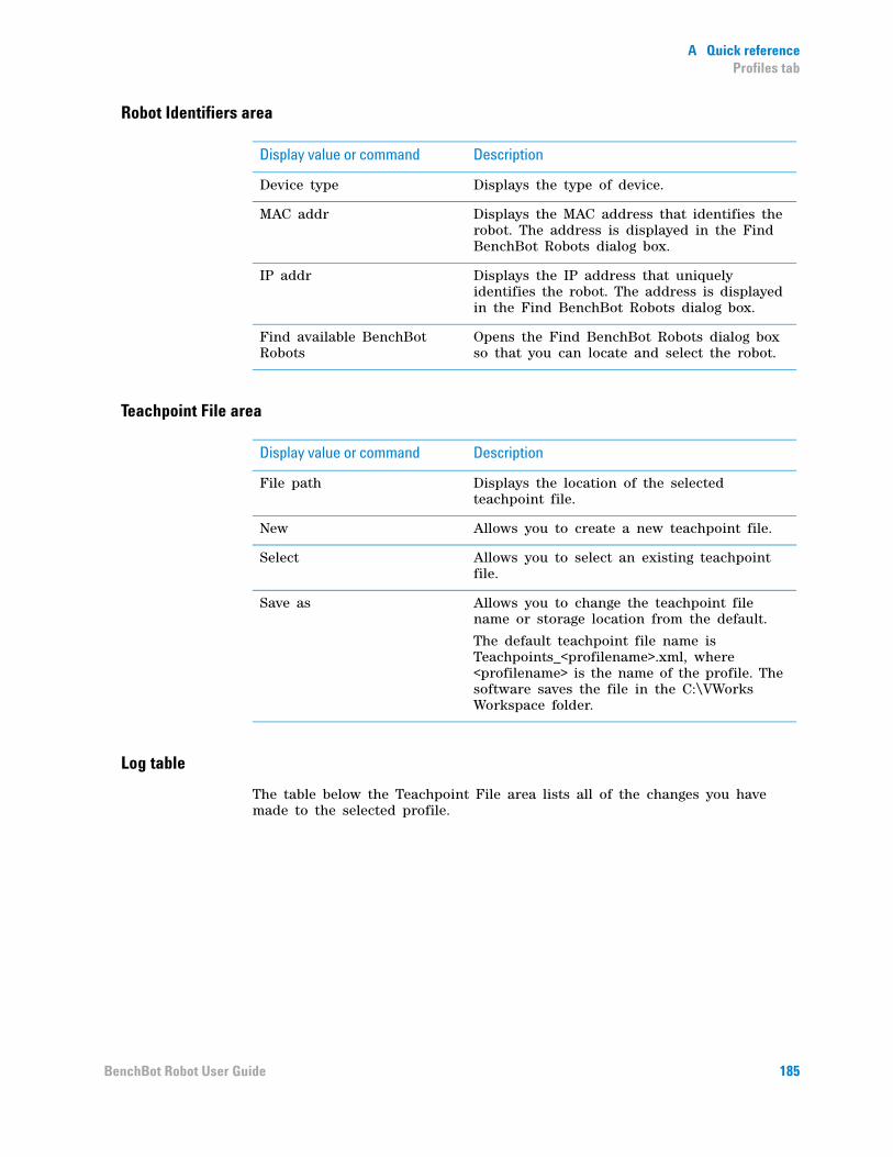
A Quick referenceProfiles tab
Robot Identifiers area
Teachpoint File area
Log table
The table below the Teachpoint File area lists all of the changes you have made to the selected profile.
Display value or command Description
Device type Displays the type of device.
MAC addr Displays the MAC address that identifies the robot. The address is displayed in the Find BenchBot Robots dialog box.
IP addr Displays the IP address that uniquely identifies the robot. The address is displayed in the Find BenchBot Robots dialog box.
Find available BenchBot Robots
Opens the Find BenchBot Robots dialog box so that you can locate and select the robot.
Display value or command Description
File path Displays the location of the selected teachpoint file.
New Allows you to create a new teachpoint file.
Select Allows you to select an existing teachpoint file.
Save as Allows you to change the teachpoint file name or storage location from the default.
The default teachpoint file name is Teachpoints_<profilename>.xml, where <profilename> is the name of the profile. The software saves the file in the C:\VWorks Workspace folder.
185BenchBot Robot User Guide

A Quick referenceProfiles tab
186 BenchBot Robot User Guide

BenchBot RobotUser Guide
B
Orderable parts
This appendix lists the BenchBot Robot parts you can order from Automation Solutions. The topics are:
• “Ordering information” on page 188
• “Parts list” on page 189
187

B Orderable partsOrdering information
Ordering information
Contacting Customer Service
To order spare parts, contact Automation Solutions Customer Service using one of the following methods:
Be sure to provide the part numbers of the items you need.
Related information
Contact method Information
Telephone 1.866.428.9811
+1.408.345.8356
Email [email protected]
For information about... See...
Reporting problems “Reporting problems” on page 165
BenchBot Robot parts list “Parts list” on page 189
188 BenchBot Robot User Guide
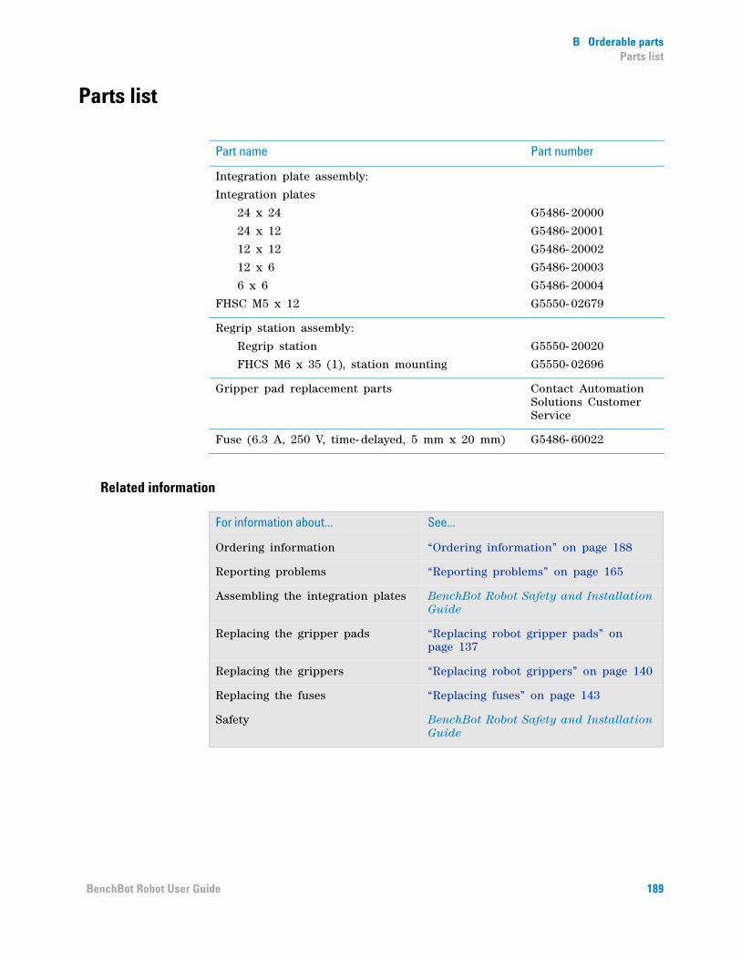
B Orderable partsParts list
Parts list
Related information
Part name Part number
Integration plate assembly:
Integration plates
24 x 24
24 x 12
12 x 12
12 x 6
6 x 6
FHSC M5 x 12
G5486- 20000
G5486- 20001
G5486- 20002
G5486- 20003
G5486- 20004
G5550- 02679
Regrip station assembly:
Regrip station
FHCS M6 x 35 (1), station mounting
G5550- 20020
G5550- 02696
Gripper pad replacement parts Contact Automation Solutions Customer Service
Fuse (6.3 A, 250 V, time- delayed, 5 mm x 20 mm) G5486- 60022
For information about... See...
Ordering information “Ordering information” on page 188
Reporting problems “Reporting problems” on page 165
Assembling the integration plates BenchBot Robot Safety and Installation Guide
Replacing the gripper pads “Replacing robot gripper pads” on page 137
Replacing the grippers “Replacing robot grippers” on page 140
Replacing the fuses “Replacing fuses” on page 143
Safety BenchBot Robot Safety and Installation Guide
189BenchBot Robot User Guide

B Orderable partsParts list
190 BenchBot Robot User Guide
Index
IndexAA1-well orientation, 46, 48, 57Approach Distance parameter, 61Approach Height parameter, 61
BBenchBot Diagnostics, 13
Cycler tab, 88described, 98Jog/Move tab, 71, 109log area, 101Profiles tab, 30Robot Status area, 100Setup tab, 119Teachpoints tab, 47
BenchBot Robotadding in device file, 20, 25arm, 4axes, 2base, 4bicep, 5closing grippers, 122described, 2disabling and enabling motors, 113, 115elbow, 5emergency stop, 95emergency-stop pendant, 8error messages, 157firmware installation, 131forearm, 5grippers, 5hand, 5installing teaching plate, 53IP address, 32jog increments, 110jogging, 109, 110joints, 5MAC address, 32maintenance, 134mast, 4, 5movements, 2moving to safe zone, 106moving to teachpoint, 71multiple robots in a system, 31opening grippers, 122orientation coordinates, 44, 45orientation information, 46orientations, 58picking up labware from a teachpoint, 74placing labware at a teachpoint, 76
preparing for a run, 92profile, 29, 39recovering from emergency stop, 148regrip station, 9regrip stations, 59removing teaching plate, 54restoring existing firmware, 131shoulder, 5specifying A1-well orientation, 57specifying labware orientation, 57speed, selecting, 117stopping in an emergency, 95teach button, 6Teach Mode, 53teaching plate, 9, 52, 53teachpoint file, 35, 51teachpoints, creating, 55teachpoints, defined, 45teachpoints, editing, 81teachpoints, examples of, 49teachpoints, replacing, 84teachpoints, saving, 69teachpoints, setting using labware, 70teachpoints, verifying, 71transferring labware between teachpoints, 78turning off, 21turning on, 21wrist, 5
bicep, robot, 5
CCartesian space, 109Close command (BenchBot grippers), 123communication setup, 31context-sensitive help, xiii
Ddescription
BenchBot Robot, 2device files
adding devices, 25creating, 14, 24defined, 23saving, 24
devices, 93adding to device file, 25communicating with, 27, 29defined, 23deleting in software, 27initializing, 27profiles in, 29
191BenchBot Robot User Guide
Index
diagnostics softwaredescribed, 13version number, x
disabling robot motors (BenchBot Robot), 113, 115dry runs, 94dry runs, described, 94
Eediting, 39elbow, robot, 5electrical requirements, 153EMERGENCY STOP
buttons, 148procedure, 95recovering from, 148
emergency-stop pendant (BenchBot Robot), 8enabling robot motors (BenchBot Robot), 113, 115errors
hardware, 153messages (BenchBot Robot), 157reporting, 165, 166servo, 151software, 148teachpoint, 94
FFind BenchBot Robots dialog box, 32firmware, 131
backing up, 129installing (BenchBot Robot), 131restoring, 131updating, 127
forearm, robot, 5fuses
replacing, 143troubleshooting, 153
GGripper offset parameter, 65gripper pads
cleaning, 135replacing, 137
gripperschanging settings, 125described, 5homing, 103opening and closing, 122opening and closing (BenchBot Robot), 122opening and closing manually, 54replacing, 140
guidelines for setting teachpoints, 48, 52
Hhand, robot, 5hardware
errors, 153, 165overview, 4
hominggrippers, 103robot, 103
IIP address, BenchBot Robot, 32
Jjob roles for readers of this guide, xjogging the robot, 109, 110Joint space selection, 109joints, robot, 5
Kknowledge base, xii
Llabware
definition, 14, 154landscape orientation, 46orientation (BenchBot Robot), 46, 48, 57picking up from teachpoint (BenchBot Robot), 74portrait orientation, 46transferring between teachpoints (BenchBot Robot),
78landscape labware orientation, 46left-arm orientation, 47liquid-handling tubing, 134log, 101
MMAC address, BenchBot Robot, 32maintenance, 134mast, 4, 5Max gripper offset parameter, 65Min gripper offset parameter, 65Move to robot zone command (BenchBot Robot), 107
Oonline help, xiiOpen command (BenchBot grippers), 123orientation coordinates, 44, 45orientation information, 46
A1 well, 46labware, 46robot arm bend, 47
192 BenchBot Robot User Guide

Index
PPDF guide, xiiplugins
loading, 25storage location, 25
portrait labware orientation, 46power
connection, 153turning off the robot, 21turning on the robot, 21
profiles, 39creating, 29defined, 29described, 13, 29initializing, 37managing, 39saving, 36selecting, 26
protocol runsperforming dry runs, 94planning for, 93setup guidelines, 93starting, 14stopping in an emergency, 95
Rrecovering the system, 148regrip stations, 9
described, 59designating teachpoints as, 59
Reload Plugins command, 25restoring existing (BenchBot Robot), 131right-arm orientation, 47robot
adding in device file, 25axes (BenchBot Robot), 2, 109homing, 103jog increments (BenchBot Robot), 110jogging (BenchBot Robot), 110opening and closing grippers (BenchBot Robot), 122recovering from servo errors, 151speed, selecting (BenchBot Robot), 117
robot arm, 4robot base, 4robot communication, 31robot gripper pads, maintaining, 134robot grippers
closing (BenchBot Robot), 122offset (BenchBot Robot), 65opening (BenchBot Robot), 122
robot motorsdisabling and enabling (BenchBot Robot), 113, 115stopping, 115
robot speedchanging, 117changing the definitions of, 119
robot status, BenchBot, 100robot zone, 106
moving to, 106robot-arm bend orientation, 47run
preparing for, 92
Ssafety
EMERGENCY STOP, 95general information, 3
servo errors, recovering from, 151setting up the robot, 20setup workflow
BenchBot Robot, 20, 42shoulder, robot, 5software
errors, 148, 157, 165reporting errors, 165version number, x, 165
speed, selectingBenchBot Robot, 117
status, BenchBot, 100stopping the robot, 95, 115
Tteach button, robot, 6Teach Mode command, 53teaching plate, 9, 52, 53, 54teachpoint files, 34teachpoints
A1-well orientation (BenchBot Robot), 57coordinates, changing, 67creating (BenchBot Robot), 55creating a copy (BenchBot Robot), 86defined (BenchBot Robot), 13, 45deleting (BenchBot Robot), 86editing (BenchBot Robot), 81file (BenchBot Robot), 35, 51labware orientation (BenchBot Robot), 57moving to (BenchBot Robot), 71naming (BenchBot Robot), 56orientation coordinates, 44, 45orientation information, 46picking up labware from (BenchBot Robot), 74placing labware at (BenchBot Robot), 76planning, 44profile references (general), 29renaming (BenchBot Robot), 86replacing (BenchBot Robot), 84saving, 69
193BenchBot Robot User Guide
Index
setting (BenchBot Robot), 48setting, using labware (BenchBot Robot), 70storage location, 51verifying (BenchBot Robot), 71
troubleshooting, 13, 97, 133hardware errors, 153
Uuser accounts, 14user guide
described, xrelated guides, xi
Vversion numbers, software, x
WWindows registry files, 29workflows
BenchBot Robot setup, 20, 42preparing for a run, 92preparing for protocol runs, 92setting up the robot, 20
wrist, robot, 5
XX coordinate, 67
YY coordinate, 67Yaw, 67
ZZ coordinate, 67
194 BenchBot Robot User Guide


s1
User Guide
G5486-90003
Revision B, March 2014