dip-8 so8 current is high or low, according to the presence
TRANSCRIPT

Rev 2October 2005 1/12
12
TDA0161
Proximity Detectors
Features 10mA Output Current
Oscillator Frequency 10MHz
Supply Voltage +4 to +35V
DescriptionThese monolithic integrated circuits are designedfor metallic body detection by sensing variationsin high frequency Eddy current losses. Using anexternally-tuned circuit, they act as oscillators.The output signal level is altered by anapproaching metallic object.
The output signal is determined by supply currentchanges. Independent of supply voltage, thiscurrent is high or low, according to the presenceor absence of a closely located metallic object.
SO8
DIP-8
www.st.com
Block Diagram

TDA0161
2/12
Contents
1 Connections . . . . . . . . . . . . . . . . . . . . . . . . . . . . . . . . . . . . . . . . . . . . . . . . . 3
2 Electrical ratings . . . . . . . . . . . . . . . . . . . . . . . . . . . . . . . . . . . . . . . . . . . . . . 4
2.1 Electrical characteristics . . . . . . . . . . . . . . . . . . . . . . . . . . . . . . . . . . . . . . . . . 4
3 Operating Mode . . . . . . . . . . . . . . . . . . . . . . . . . . . . . . . . . . . . . . . . . . . . . . . 5
4 Typical Applications . . . . . . . . . . . . . . . . . . . . . . . . . . . . . . . . . . . . . . . . . . . 6
5 Package Mechanical Data . . . . . . . . . . . . . . . . . . . . . . . . . . . . . . . . . . . . . . . 8
6 Order codes . . . . . . . . . . . . . . . . . . . . . . . . . . . . . . . . . . . . . . . . . . . . . . . . . 10
7 Revision history . . . . . . . . . . . . . . . . . . . . . . . . . . . . . . . . . . . . . . . . . . . . . . 11

TDA0161 1 Connections
3/12
1 Connections
Figure 1. Pin Connections (top view)
2 Electrical ratings TDA0161
4/12
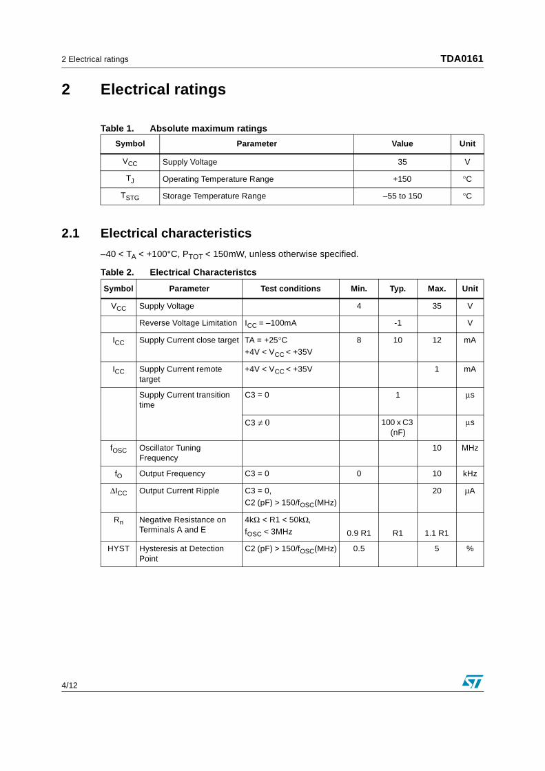
2 Electrical ratings
Table 1. Absolute maximum ratings
2.1 Electrical characteristics
–40 < TA < +100°C, PTOT < 150mW, unless otherwise specified.
Symbol Parameter Value Unit
VCC Supply Voltage 35 V
TJ Operating Temperature Range +150 °C
TSTG Storage Temperature Range –55 to 150 °C
Table 2. Electrical Characteristcs
Symbol Parameter Test conditions Min. Typ. Max. Unit
VCC Supply Voltage 4 35 V
Reverse Voltage Limitation ICC = –100mA -1 V
ICC Supply Current close target TA = +25°C+4V < VCC < +35V
8 10 12 mA
ICC Supply Current remote target
+4V < VCC < +35V 1 mA
Supply Current transition time
C3 = 0 1 µs
C3 ≠ 0 100 x C3 (nF)
µs
fOSC Oscillator Tuning Frequency
10 MHz
fO Output Frequency C3 = 0 0 10 kHz
∆ICC Output Current Ripple C3 = 0,
C2 (pF) > 150/fOSC(MHz)
20 µA
Rn Negative Resistance on Terminals A and E
4kΩ < R1 < 50kΩ,
fOSC < 3MHz 0.9 R1 R1 1.1 R1
HYST Hysteresis at Detection Point
C2 (pF) > 150/fOSC(MHz) 0.5 5 %

TDA0161 3 Operating Mode
5/12
3 Operating Mode
Between pins 3 and 7, the integrated circuit acts like a negative resistor with a value equal to that of the external resistor R1 (connected between pins 2 and 4). The oscillation stops when the tuned circuit loss resistance (Rp) becomes smaller than R1. As a result, ICC(close) = 10mA (pins 1 and 6). The oscillation is sustained when Rp is higher than R1, and ICC(remote) = 1mA (pins 1 and 6). Eddy currents induced by coil L1 in a metallic body determine the value of Rp.
Figure 2. Electrical Scheme
Icc(close)
Icc(remote)
If the circuit is used at frequency higher than 3MHz, it is recommended to connect a capacitor of 100pF between pins 7 and 6

4 Typical Applications TDA0161
6/12
4 Typical Applications
#) _.Ingot steel target
##).The above results are obtained with single wire coil. When using Litz wire instead of single wire, the parallel resistance of the coil becomes higher and value of R1 may be increased, resulting in better sensitivity
Figure 3. Application Interface Connection Diagram
Table 3. Detection Range
Detection Range (#) L1 (µH) C1 (pF) fOSC (kHz) R1 (kΩ) C2 (pF)
2mm 30 (1) 120 2650 6.8 47
5mm 300 (2) 470 425 27 470
10mm 2160 (3) 4700 50 27 3300
Table 4. Coil Characteristics
Core Coil Former Wire (##) Number of Turns
1 Cofelec 432 FP 9 x 5 SE 1/2 Car 091 - 2 THOMSON Fils et Câbles Thomrex 14
(14 / 100mm)
40
2 Cofelec 432 FP 14 x 8 SE 1/2 Car 142 - 2 100
3 Cofelec 432 FP 26x 16 SE 1/2 Car 262 - 2 200

TDA0161 4 Typical Applications
7/12
4.1 ___Typical Application Example
Figure 4. __Detection distance

5 Package Mechanical Data TDA0161
8/12
5 Package Mechanical Data
DIM.mm inch
MIN. TYP. MAX. MIN. TYP. MAX.
A 3.3 0.130
a1 0.7 0.028
B 1.39 1.65 0.055 0.065
B1 0.91 1.04 0.036 0.041
b 0.5 0.020
b1 0.38 0.5 0.015 0.020
D 9.8 0.386
E 8.8 0.346
e 2.54 0.100
e3 7.62 0.300
e4 7.62 0.300
F 7.1 0.280
I 4.8 0.189
L 3.3 0.130
Z 0.44 1.6 0.017 0.063
P001F
Plastic DIP-8 MECHANICAL DATA

TDA0161 5 Package Mechanical Data
9/12
DIM.mm. inch
MIN. TYP MAX. MIN. TYP. MAX.
A 1.75 0.068
a1 0.1 0.25 0.003 0.009
a2 1.65 0.064
a3 0.65 0.85 0.025 0.033
b 0.35 0.48 0.013 0.018
b1 0.19 0.25 0.007 0.010
C 0.25 0.5 0.010 0.019
c1 45 (typ.)
D 4.8 5.0 0.188 0.196
E 5.8 6.2 0.228 0.244
e 1.27 0.050
e3 3.81 0.150
F 3.8 4.0 0.14 0.157
L 0.4 1.27 0.015 0.050
M 0.6 0.023
S 8 (max.)
SO-8 MECHANICAL DATA
TDA0161
10/12
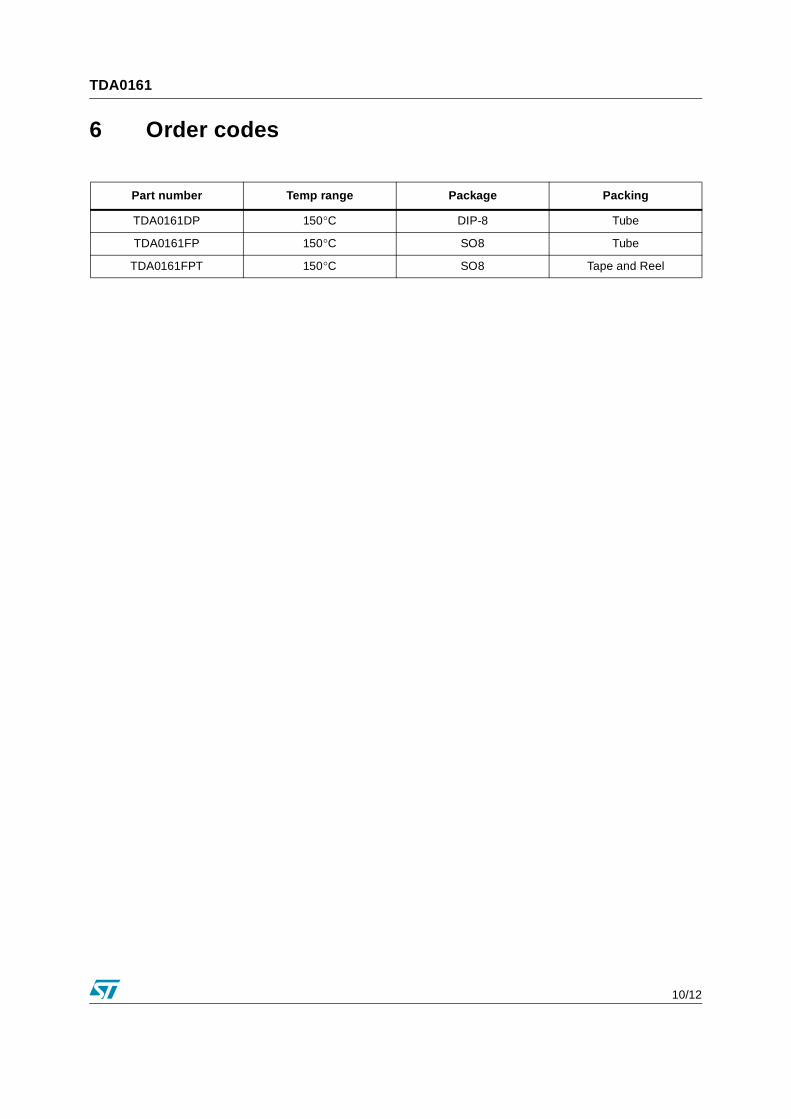
6 Order codes
Part number Temp range Package Packing
TDA0161DP 150°C DIP-8 Tube
TDA0161FP 150°C SO8 Tube
TDA0161FPT 150°C SO8 Tape and Reel
TDA0161 7 Revision history
11/12
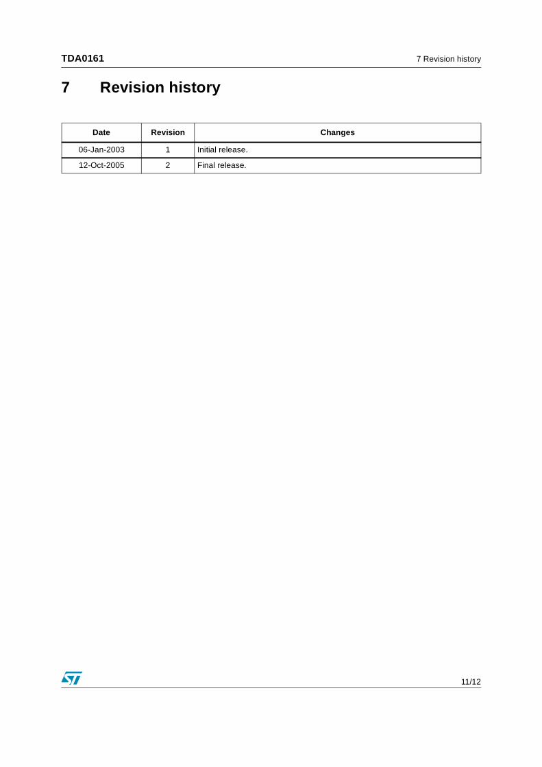
7 Revision history
Date Revision Changes
06-Jan-2003 1 Initial release.
12-Oct-2005 2 Final release.
7 Revision history TDA0161
12/12
Information furnished is believed to be accurate and reliable. However, STMicroelectronics assumes no responsibility for the consequencesof use of such information nor for any infringement of patents or other rights of third parties which may result from its use. No license is grantedby implication or otherwise under any patent or patent rights of STMicroelectronics. Specifications mentioned in this publication are subjectto change without notice. This publication supersedes and replaces all information previously supplied. STMicroelectronics products are notauthorized for use as critical components in life support devices or systems without express written approval of STMicroelectronics.
The ST logo is a registered trademark of STMicroelectronics.All other names are the property of their respective owners
© 2005 STMicroelectronics - All rights reserved
STMicroelectronics group of companies
Australia - Belgium - Brazil - Canada - China - Czech Republic - Finland - France - Germany - Hong Kong - India - Israel - Italy - Japan - Malaysia - Malta - Morocco - Singapore - Spain - Sweden - Switzerland - United Kingdom - United States of America
www.st.com