dimensionone issue user guide v2 english lit4767-iss-02 · lit4767-iss-02. user manual. 2....
TRANSCRIPT

Dimension ne
SeriesD
LIT4767-ISS-02
User Manual

2
NAVIGATION INSTRUCTIONSThe symbols in the left-hand margin of each page of the manual will enable you to carry out the following functions:
i The buttons in text below do not function. They are for illustrative purposes only.
Click on this button to display the Contents page.
Back one page.
Forward one page.
Back button.
Forward button.
Click this button to print some or all of the document (specific pages can be chosen).
Exit Click this button to exit the user guide.
! Press the Esc key to display normal Acrobat© Controls.
Contents

3
CONTENTSIntroduction . . . . . . . . . . . . . . . . . . . . . . . . . . . . . . . . . . . . . . . . . . . . . 6
General . . . . . . . . . . . . . . . . . . . . . . . . . . . . . . . . . . . . . . . . . . . . . . . . . . . . . . . .6Main features . . . . . . . . . . . . . . . . . . . . . . . . . . . . . . . . . . . . . . . . . . . . . . . . . . .6
1. Initial set-up . . . . . . . . . . . . . . . . . . . . . . . . . . . . . . . . . . . . . . . . . . 71.1 System requirements . . . . . . . . . . . . . . . . . . . . . . . . . . . . . . . . . . . . . . . . .71.2 Software installation . . . . . . . . . . . . . . . . . . . . . . . . . . . . . . . . . . . . . . . . . .8
2. Getting started . . . . . . . . . . . . . . . . . . . . . . . . . . . . . . . . . . . . . . . . 92.1 Starting DimensionOne™ . . . . . . . . . . . . . . . . . . . . . . . . . . . . . . . . . . . . . .92.2 Language selection . . . . . . . . . . . . . . . . . . . . . . . . . . . . . . . . . . . . . . . . . .112.3 Video source setup . . . . . . . . . . . . . . . . . . . . . . . . . . . . . . . . . . . . . . . . . .12
3. Operation . . . . . . . . . . . . . . . . . . . . . . . . . . . . . . . . . . . . . . . . . . . 143.1 Screen areas . . . . . . . . . . . . . . . . . . . . . . . . . . . . . . . . . . . . . . . . . . . . . . .153.2 Still capture . . . . . . . . . . . . . . . . . . . . . . . . . . . . . . . . . . . . . . . . . . . . . . . .163.3 Handling captured images . . . . . . . . . . . . . . . . . . . . . . . . . . . . . . . . . . . .16
3.3.1 Renaming a captured image . . . . . . . . . . . . . . . . . . . . . . . . . . . . . .163.3.2 Deleting a captured image . . . . . . . . . . . . . . . . . . . . . . . . . . . . . . . .16
3.4 Using the crosshair . . . . . . . . . . . . . . . . . . . . . . . . . . . . . . . . . . . . . . . . . .173.4.1 Moving the crosshair . . . . . . . . . . . . . . . . . . . . . . . . . . . . . . . . . . . .173.4.2 Rotating the crosshair . . . . . . . . . . . . . . . . . . . . . . . . . . . . . . . . . . .173.4.3 Changing the colour of the crosshair . . . . . . . . . . . . . . . . . . . . . . .173.4.4 Resetting the crosshair position . . . . . . . . . . . . . . . . . . . . . . . . . . .17
3.5 Changing the display units . . . . . . . . . . . . . . . . . . . . . . . . . . . . . . . . . . . .183.6 Controlling the image magnification . . . . . . . . . . . . . . . . . . . . . . . . . . . .18

4
3.7 Add annotations . . . . . . . . . . . . . . . . . . . . . . . . . . . . . . . . . . . . . . . . . . . .193.7.1 Adding shapes . . . . . . . . . . . . . . . . . . . . . . . . . . . . . . . . . . . . . . . . . .193.7.2 Editing shapes . . . . . . . . . . . . . . . . . . . . . . . . . . . . . . . . . . . . . . . . . .203.7.3 Adding text . . . . . . . . . . . . . . . . . . . . . . . . . . . . . . . . . . . . . . . . . . . . .213.7.4 Editing text . . . . . . . . . . . . . . . . . . . . . . . . . . . . . . . . . . . . . . . . . . . . .223.7.5 Adding call-out arrows . . . . . . . . . . . . . . . . . . . . . . . . . . . . . . . . . . .223.7.6 Editing call-out arrows . . . . . . . . . . . . . . . . . . . . . . . . . . . . . . . . . . .23
3.8 Dimensioning . . . . . . . . . . . . . . . . . . . . . . . . . . . . . . . . . . . . . . . . . . . . . . .243.8.1 Displaying the dimension icons . . . . . . . . . . . . . . . . . . . . . . . . . . .243.8.2 Resolution and precision . . . . . . . . . . . . . . . . . . . . . . . . . . . . . . . . .243.8.3 Point . . . . . . . . . . . . . . . . . . . . . . . . . . . . . . . . . . . . . . . . . . . . . . . . . .253.8.4 Line . . . . . . . . . . . . . . . . . . . . . . . . . . . . . . . . . . . . . . . . . . . . . . . . . . .263.8.5 Circle . . . . . . . . . . . . . . . . . . . . . . . . . . . . . . . . . . . . . . . . . . . . . . . . .273.8.6 Length . . . . . . . . . . . . . . . . . . . . . . . . . . . . . . . . . . . . . . . . . . . . . . . .283.8.7 Angle . . . . . . . . . . . . . . . . . . . . . . . . . . . . . . . . . . . . . . . . . . . . . . . . . .293.8.8 Calibration . . . . . . . . . . . . . . . . . . . . . . . . . . . . . . . . . . . . . . . . . . . . .30
3.9 Image control . . . . . . . . . . . . . . . . . . . . . . . . . . . . . . . . . . . . . . . . . . . . . . .313.10 Output options . . . . . . . . . . . . . . . . . . . . . . . . . . . . . . . . . . . . . . . . . . . . .32
4. Settings . . . . . . . . . . . . . . . . . . . . . . . . . . . . . . . . . . . . . . . . . . . . . 334.1 Accessing the settings menu . . . . . . . . . . . . . . . . . . . . . . . . . . . . . . . . . .344.2 Software version . . . . . . . . . . . . . . . . . . . . . . . . . . . . . . . . . . . . . . . . . . . .354.3 Read/Write settings . . . . . . . . . . . . . . . . . . . . . . . . . . . . . . . . . . . . . . . . . .354.4 Backup and restore . . . . . . . . . . . . . . . . . . . . . . . . . . . . . . . . . . . . . . . . . .354.5 Set language . . . . . . . . . . . . . . . . . . . . . . . . . . . . . . . . . . . . . . . . . . . . . . .354.6 Security . . . . . . . . . . . . . . . . . . . . . . . . . . . . . . . . . . . . . . . . . . . . . . . . . . .36
4.6.1 Initial security setup . . . . . . . . . . . . . . . . . . . . . . . . . . . . . . . . . . . . .364.6.2 General security setup . . . . . . . . . . . . . . . . . . . . . . . . . . . . . . . . . . .37
4.7 File locations . . . . . . . . . . . . . . . . . . . . . . . . . . . . . . . . . . . . . . . . . . . . . . .38

5
4.8 Video settings . . . . . . . . . . . . . . . . . . . . . . . . . . . . . . . . . . . . . . . . . . . . . .394.8.1 Pixel resolution . . . . . . . . . . . . . . . . . . . . . . . . . . . . . . . . . . . . . . . . .394.8.2 Line thickness for overlays . . . . . . . . . . . . . . . . . . . . . . . . . . . . . . .394.8.3 Image source . . . . . . . . . . . . . . . . . . . . . . . . . . . . . . . . . . . . . . . . . . .394.8.4 Camera choice . . . . . . . . . . . . . . . . . . . . . . . . . . . . . . . . . . . . . . . . . .394.8.5 Video source properties . . . . . . . . . . . . . . . . . . . . . . . . . . . . . . . . . .39
4.9 Desktop . . . . . . . . . . . . . . . . . . . . . . . . . . . . . . . . . . . . . . . . . . . . . . . . . . .404.9.1 Lock window layout . . . . . . . . . . . . . . . . . . . . . . . . . . . . . . . . . . . . .404.9.2 Display inch/mm button . . . . . . . . . . . . . . . . . . . . . . . . . . . . . . . . . .404.9.3 Display dms/dd button . . . . . . . . . . . . . . . . . . . . . . . . . . . . . . . . . . .404.9.4 Display keyboard button . . . . . . . . . . . . . . . . . . . . . . . . . . . . . . . . .404.9.5 Shutdown computer on exit . . . . . . . . . . . . . . . . . . . . . . . . . . . . . . .404.9.6 Display at full screen size . . . . . . . . . . . . . . . . . . . . . . . . . . . . . . . . .404.9.7 Restore defaults at launch . . . . . . . . . . . . . . . . . . . . . . . . . . . . . . . .404.9.8 Crosshair to click . . . . . . . . . . . . . . . . . . . . . . . . . . . . . . . . . . . . . . .40
4.10 Display formats . . . . . . . . . . . . . . . . . . . . . . . . . . . . . . . . . . . . . . . . . . . .414.10.1 Resolution settings . . . . . . . . . . . . . . . . . . . . . . . . . . . . . . . . . . . . .414.10.2 Current inch/mm flag . . . . . . . . . . . . . . . . . . . . . . . . . . . . . . . . . . .414.10.3 Current dms/dd . . . . . . . . . . . . . . . . . . . . . . . . . . . . . . . . . . . . . . . .414.10.4 Use comma for radix . . . . . . . . . . . . . . . . . . . . . . . . . . . . . . . . . . . .414.10.5 Date format . . . . . . . . . . . . . . . . . . . . . . . . . . . . . . . . . . . . . . . . . . .41
4.11 Sounds . . . . . . . . . . . . . . . . . . . . . . . . . . . . . . . . . . . . . . . . . . . . . . . . . . .415. Using custom settings files with Mantis Elite Cam HD and Lynx EVO Smart Cam . . . . . . . . . . . . . . . . . . . . . . . . . . . . . . . . . . 42Contacts . . . . . . . . . . . . . . . . . . . . . . . . . . . . . . . . . . . . . . . . . . . . . . . 43

6
IntroductionGeneralThe DimensionOne™ software is designed to provide users of Vision Engineering’s stereo microscopes, image capture and annotation capability with ultimate simplicity. Large icons and a ‘menuless’ format means the software can be used seamlessly to simply capture an image or for on-screen dimensioning.
Main featuresSimply capture an image DimensionOne™ can capture an image with one click of the mouse, or a touch of the screen. The design allows maximum emphasis on the live and captured image, making annotation easier and clearer.
Annotating captured images DimensionOne™ has one sans-serif font and a palette of colours, so maximum contrast can be obtained between the captured image and the annotation.
Dimensioning On-screen dimensioning can be utilised on any captured image with a choice of circles, lines, points, angles and distances.
Additionally, there are a range of powerful constructions available including creating intersection of lines, or bolt circles etc.
Touch-screen capability Simply touch the screen to capture an image, annotate it or measure it. With the usual swipe, pinch and touch of the fingers, the touch-screen facility minimises the use of the mouse making the image capture process even easier.
Opacity change DimensionOne™ allows for the captured image to be modified with a change in opacity from 0 to 100%.

7
1. Initial set-up1.1 System requirementsThe following are the minimum system requirements that will enable DimensionOne™ to run efficiently:
• Operating system Microsoft® Windows® 7 - 64-bit
• CPU type Intel® Core™ i5, with CPU clock of 2.5 GHz
• Chipset Intel H81 chipset, or equivalent
• Display card Dedicated video graphics card, capable of 1600x1200 with live video streaming, or Intel HD4000 “on-board” video graphics card
• Display resolution 1600x1200
• Memory 4GB
• Disk space 200GB solid state hard drive - for installation, plus data and image storage
• USB USB2.0 ports (x4)
• Adobe® Flash® Adobe® Flash® Player v15
• Other Windows-compatible mouse and keyboard
8
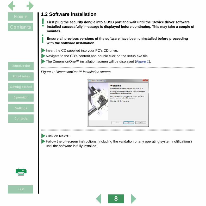
1.2 Software installation
! First plug the security dongle into a USB port and wait until the ‘Device driver software installed successfully’ message is displayed before continuing. This may take a couple of minutes.
i Ensure all previous versions of the software have been uninstalled before proceeding with the software installation.
XInsert the CD supplied into your PC’s CD drive.
XNavigate to the CD’s content and double click on the setup.exe file.
XThe DimensionOne™ installation screen will be displayed (Figure 1):
Figure 1: DimensionOne™ installation screen
XClick on Next>.
XFollow the on-screen instructions (including the validation of any operating system notifications) until the software is fully installed.

9
2. Getting startedThis section will describe the following:
• Starting DimensionOne™ (see below)
• Language selection (page 11)
• Video source setup (page 12)
2.1 Starting DimensionOne™Double click on the DimensionOne™ icon D on your PC’s desktop. If no security settings have been changed, the Home screen will be displayed (Figure 2).
Figure 2: Home screen
If users have been assigned passwords, the Login screen will be displayed (Figure 3)

10
Figure 3: Login screen
To login, proceed as follows:
XIf necessary, click on the required language.
XSelect the appropriate user button.
XUsing the on-screen keyboard key in your password and click Done. The Home screen will now be displayed.
i If you click on Exit, DimensionOne™ will be closed.

11
2.2 Language selectionIf necessary, select your preferred language as follows:
XClick on the DimensionOne™ logo u to reveal the drop down menu (Figure 4).
XClick on the Settings button v. The Settings screen will be displayed (Figure 5).
Figure 4: Settings button
Figure 5: Settings screen
XClick the Languages button, click the required language from the list and click Done to return to the Settings screen.
XClick Done again to return to the Home screen.
vu

12
2.3 Video source setupIf the default graphic is displayed in the capture area of the screen, proceed as follows to select the required video source:
XFrom the Home screen (Figure 6), click on the DimensionOne™ logo u and then click on the Settings button v from the drop down menu. The Settings menu will be displayed (Figure 7).
Figure 6: Setup button
Figure 7: Settings menu
XClick the Video button. The Video setup screen will be displayed (Figure 8).
vu

13
Figure 8: Video setup screen
XWhen using Mantis Elite Cam HD or Lynx EVO Smart Cam select uEye from Image source drop down list.
XWhen using other cameras select DirectShow from Image source drop down list.
XSelect the desired camera and camera resolution option from the Camera choice drop down list.
XWhen the selection is complete, click Done to return to the Settings menu and again to return to the Home screen.
i Before changes to the video settings can take effect, the software must be restarted.

14
3. Operation
i To view this manual whilst DimensionOne™ is running, hold down the Alt key and press the Tab key to toggle between the two.
This section will describe the following functions:
• Screen areas (page 15)
• Still capture (page 16)
• Handling captured images (page 16)
• Using the crosshair (page 17)
• Changing the display units (page 18)
• Controlling the image magnification (page 18)
• Add annotation (page 19)
• Dimensioning (page 24)
• Image control (page 31)
• Output options (page 32)

15
3.1 Screen areasThe Home screen consists of the following areas:
• u Status bar
• v Image area
• w Image zoom control
• x Annotation controls
• y Output options
• z Dimension controls
• { Measurement display area
• | Image list
Figure 9: Screen areas
uv
w x y z
{
|

16
3.2 Still captureTo capture a still from the image being displayed in the Image area, proceed as follows:
XUse the controls on the video source to obtain the desire image.
XClick on the icon in the Status bar. The icon will now be displayed as and a still image will be displayed at the top of the Image list. It will be highlighted blue to indicate it is currently being displayed in the image area and its filename will be displayed at the left-hand end of the status bar.
i The default filename allocated to a still image is created from the date and time it was captured.
XClick on the icon, to return to displaying live video in the image area.
i If an annotation (page 19) or dimension (page 24) is added to an image whilst in the video mode, a still capture will be taken automatically.
3.3 Handling captured imagesCaptured images can be renamed to aid identification, or deleted when they are no longer required, as follows:
3.3.1 Renaming a captured image XClick on the image in the Image list which is to be renamed (scroll through the list if necessary). It will be highlighted blue and its current filename will be displayed at the left-hand end of the status bar.
XClick on the filename. It will be highlighted in green.
XEither type in the filename required, or click on the name again to edit the existing filename.
XWhen the filename has been changed, click Done.
3.3.2 Deleting a captured image XClick on the image in the Image list which is to be deleted (scroll through the list if necessary). It will be highlighted blue and its current filename will be displayed at the left-hand end of the status bar.
XClick on the icon at the bottom right of the screen. The delete prompt will appear.
XClick Yes to delete or No to abort deletion.
i If all the images in the Image list are deleted, the Image area will display the video source or the bitmap image according to the Image source and Camera choice settings (page 12).

17
3.4 Using the crosshair
3.4.1 Moving the crosshair XTo move the crosshair in the XY plane, ensure the icon is displayed in the top left of the Image area. If the icon is displayed, click on it.
XClick and drag the mouse cursor on the Image area to move the crosshair. The movement will be reflected by the X and Y values in the Measurement display area.
XTo zero the new position of the crosshair, click the X and/or Y buttons in the Measurement display area.
3.4.2 Rotating the crosshair XTo rotate the crosshair, ensure the icon is displayed in the top left of the Image area. If the
icon is displayed, click on it.
XClick and drag the mouse cursor on the Image area to rotate the crosshair. The movement will be reflected by the Q value in the Measurement display area.
XTo zero the new angle of the crosshair, click the Q button in the Measurement display area.
3.4.3 Changing the colour of the crosshair XWith nothing selected in the Image area, click on the icon in the top left of the Image area to change the colour of the crosshair. They will change in the following order: Dark blue Yellow Light blue Magenta Black White Green (default)
3.4.4 Resetting the crosshair positionTo restore the crosshair to its default position (i.e. the centre of the image area with zero rotation), click and hold the left mouse key over the or icon for approximately 3 seconds.

18
3.5 Changing the display unitsThere are two possible unit buttons that can be displayed in the status bar:
• Inch/mm
• DD(decimal degrees)/DMS(degrees,minutes,seconds)
i To set these buttons to appear, see page 40.
XClick on these buttons to alternate between the units as required.
3.6 Controlling the image magnificationTo change the magnification of the image displayed in the Image area, proceed as follows:
XClick on the icon at the bottom left corner of the screen. A selection of icons will be displayed as follows:
Displays the entire image. Displays the full width of the image.
Displays the image at full size. Drag over area to magnify.
Zoom in. Zoom out.
i When the icon is selected, the full width of the image will be displayed but this may cause some of its height to be cropped.
i The scrolling wheel on a compatible mouse can be used to zoom in and out.
i To pan the image in the Image area, hold down the right mouse button and drag it as required.

19
3.7 Add annotations
i If, after adding annotation to an image, another image is selected from the Image list, the annotation on the original image cannot be edited or deleted. However, new annotation can be added and edited.
Annotations in the form of rectangles, circles, text and arrows can be added to an image as follows:
3.7.1 Adding shapes XSelect the or icon as required and click and drag the cursor in the Image area from where the shape should start until the required area is covered.
i If the image being displayed was direct from the video source a still capture will be taken automatically and an image will be added to the top of the image list highlighted in blue.
i Whilst the shape is being drawn, the Measurement display area will display the position of the centre of the shape relative to the zeroed position of the crosshair (X and Y), and the width (W) and height (H) for rectangles and the diameter (D) for circles.
XWhen the shape is completed (the mouse button released), the icon will no longer be highlighted and the position of the crosshair will be displayed.

20
3.7.2 Editing shapes XClick on the border of an existing shape. It will now be displayed as shown below.
Figure 10: Shape editing
XTo move a rectangle, select it and then click and drag it from one of its sides to the required position.
XTo move a circle, select it and then click and drag from the circle at its centre to the required position.
XTo re-size a rectangle, click and drag any of the circles in its corners until it is the required size.
i The aspect ratio of a rectangle can also be changed when it is re-sized.
XTo re-size a circle, click and drag the circle at its edge until it is the required size.
XTo change the colour of a shape, select it and then click on the icon in the top left of the Image area. The shape will change colour in the following order: Dark blue Yellow Light blue Magenta Black White Green (default)
XTo delete a shape, select it and click the icon at the bottom right of the screen.
Selected
Selected
Not selected
Not selected

21
3.7.3 Adding text
i When text is added to an image, it will be in the form of a call-out arrow attached to a text box.
XTo add text to an image, click the icon and then click and drag from where the point of the call-out arrow is required. Release the mouse when the text box is in the required position.
i Whilst the text box is being drawn, the Measurement display area will display the position of the centre of the box relative to the zeroed position of the crosshair (X and Y), and the width (W) and height (H) of the box.
XTo add text, click the text box to select it (Figure 11).
Figure 11: Text box selection
XKey in the required text and click the a icon to make the text smaller or the A icon to make it bigger.
SelectedNot selected

22
3.7.4 Editing text XTo re-size the text box, select it and then click and drag on one of the corner circles until it is the required size and in required position (the call-out arrow head will remain in the same position).
XTo move the position of the call-out arrow head, select it and then click and drag the arrow head circle until it is in the required position.
XTo edit the text in a text box, select it. The text cursor, although not shown, is always at the end of the text. Use the Backspace key to delete text or key in text to add it to the end of existing text.
XTo change the colour of a text box, select it and then click on the icon in the top left of the Image area. The shape will change colour in the following order: Dark blue Yellow Light blue Magenta Black White Green (default)
XTo delete a text box, select it and then click the icon at the bottom right of the screen.
3.7.5 Adding call-out arrows
XTo add a call-out arrow, click the icon and click and drag the cursor from where the arrow head is required.
XRelease the cursor when the length and position is as required.

23
3.7.6 Editing call-out arrows XTo edit a call-out arrow, click on it to select it (Figure 12).
Figure 12: Call-out arrow selection
XTo move the position of the call-out arrow head, select it and then click and drag the arrow head circle until it is in the required position.
XTo move the position of the call-out arrow tail, select it and then click and drag the arrow tail circle until it is in the required position.
XTo delete a call-out arrow, select it and then click the icon at the bottom right of the screen.
SelectedNot selected

24
3.8 DimensioningThe dimensioning functions are as follows:
• Point This displays the X Y coordinates of a point relative to the current crosshair zero position.
• Line This measures a line using between 2 and 9 points.
• Circle This measures the diameter of a circle derived from 3 or more points
• Length The measure the distance between 2 points or features
• Angle This measures the angle between two existing lines, or derived from 4 or more points
! Before using the dimensioning tools, either for the first time or after the magnification of the source video has changed, carry out the calibration procedure detailed on page 30.
i Up to 9 points can be selected when dimensioning a Point, Line, Circle or angles.
i Points can be entered by holding down the left mouse button and right clicking.
3.8.1 Displaying the dimension icons
XClick the icon to display the dimension icons.
3.8.2 Resolution and precisionThe terms resolution and precision have totally different meanings in the context of this dimensioning system and should not be confused with each other.
Resolution The term resolution refers to the accuracy of the equipment generating the video image in the Image area. The higher the precision of the equipment, the more accurate the image supplied to the Image area.
Precision The term precision is directly related to the operators ability to place points on the image accurately. The more precise the operator is about placing points on the image, the more accurate the readings will be.

25
3.8.3 Point
XClick the icon. The Point position box will be displayed in the Measurement display area (Figure 13).
Figure 13: Point position box
XPosition the crosshair at the point position is to be measured and click in the Points Entry box. The counter will display 1.
i Up to 9 points can be placed and the resulting point will be an average of those points.
XClick to delete the each point and make another one or click to accept.
XWhen accepted, a box displaying the XY coordinates relative to the crosshair current zero position will be displayed.
XTo delete the measurement box, select it and click .

26
3.8.4 Line XClick the icon. The Line box will be displayed in the Measurement display area (Figure 14).
Figure 14: Line box
XPosition the crosshair at the first point in the required line and click in the Points entry box. The counter will display 1.
XPosition the crosshair at the second point in the required line and click in the Points Entry box. The counter will display 2.
i Up to 9 points can be placed and the resulting line will be an average of those points.
XClick to delete either point and make another one or click to accept the position of both points.
XTo delete the line, select it and click .

27
3.8.5 Circle XClick the icon. The Circle box will be displayed in the Measurement display area (Figure 15).
Figure 15: Circle box
XPosition the crosshair at the first point in the required circle and click in the Points entry box. The counter will display 1.
XPosition the crosshair at the second point in the required circle and click in the Points Entry box. The counter will display 2.
XRepeat this for a third time.
i Up to 9 points can be placed and the resulting circle will be an average of those points.
XClick to delete each point and make more or click to accept the position of all the points.
XWhen accepted, the diameter of a circle passing through the average position of all points will be displayed.
XTo measure the radius of an arc, click the icon (which appears at the base of the screen after has been clicked) .
XTo delete the circle, select it and click .

28
3.8.6 Length
XClick the icon. The Length box will be displayed in the Measurement display area (Figure 16).
Figure 16: Length box
XPosition the crosshair at the first point in the required length and click in the Points entry box. The counter will display 1.
XPosition the crosshair at the second point in the required length and click in the Points Entry box. The counter will display 2.
XClick to delete each point and make another one or click to accept the position of both points.
XWhen accepted, the length of the line will be displayed.
XIf measuring between circles or a line and a circle, click the Icon (which appears at the base of the screen after has been clicked) for alternative distances
XTo delete the length, select it and click .

29
3.8.7 Angle XClick the icon. The Angle box will be displayed in the Measurement display area (Figure 17).
Figure 17: Angle box
XPosition the crosshair at the first point in the first line of the angle and click in the Points entry box. The counter will display 1.
XPosition the crosshair at the second point in the first line and click in the Points Entry box. The counter will display 2. Up to 5 points can be entered on the first line
XRepeat the above 2 steps for the second line (the remaining points up to a total of 9 can be entered here).
i Up to 9 points can be placed and the resulting lines will be an average of those points.
XClick to delete any of the points and make another one or click to accept the position of all the points.
XWhen accepted, the angle between the 2 lines will be displayed.
XTo display alternative possible angles, click the icon (which appears at the base of the screen after has been clicked) .
XTo delete the angle, select it and click .

30
3.8.8 CalibrationBefore using the dimensioning tools, either for the first time or after the magnification of the source video has changed, carry out the calibration procedure as follows:
XPlace an object of known dimensions, or the Vision calibration aid supplied, under the lens of the video source.
XOnce focussed, measure a Circle (page 27) of known dimension.
XWith the results in the Measurement display area, click and hold the left mouse button until the calibration box is displayed (Figure 18 for the Circle calibration box).
Figure 18: Circle calibration box
XClick in the D (diameter) field and enter the relevant known value.
XClick Done. The image displayed is now calibrated.

31
3.9 Image controlWhen an image has had annotations and/or dimensions added, the emphasis of image to additions can be altered so that the image is stronger than the annotations/dimensions or vice-versa.
This is achieved by the Opacity control u in the Status bar (shown in Figure 19 in the neutral position).
Figure 19: Opacity control
XClick and drag the orange slider to the left and the image is more prominent. Slide it to the right and the annotations/dimensions are more prominent (Figure 20).
Figure 20: Image control
u

32
3.10 Output options XClick on the icon to output the image currently displayed in the Image area in the following ways:
• Print This will print immediately to the default printer
• Save to file This will open the Save file dialogue box. Edit the filename (if required) and navigate to the required location (if required). Select Bitmap, JPG or PNG file type as required and click Save.
• Email This will open an new email with the file attached.

33
4. SettingsThis section describes how to setup the software to meet a user’s or a system’s individual requirements, and covers the following:
• Accessing the settings menu (page 34)
• Software version information (page 35)
• Read/Write settings (page 35)
• Backup/Restore (page 35)
• Set language (page 35)
• Security (page 36)
• File locations (page 38)
• Video settings (page 39)
• Desktop settings (page 40)
• Display formats (page 41)
• Sounds (page 41)
• Using custom settings files with Mantis Elite Cam HD and Lynx EVO Smart Cam (page 42)

34
4.1 Accessing the settings menuTo access the settings menu, proceed as follows:
XClick on the DimensionOne™ logo u to reveal the drop down menu (Figure 21).
XClick on the Settings button v. The Settings menu will be displayed (Figure 22).
Figure 21: Selecting settings
Figure 22: Settings menu
vu

35
4.2 Software versionTo access the information regarding the software, select About from the Settings menu.
4.3 Read/Write settings
i These settings are not functional.
4.4 Backup and restoreThe settings for the current user can be backed up and subsequently restored if necessary as follows:
i It is always advisable to backup information to an external source. This can be achieved by setting the backup file location accordingly (page 37).
XEnsure the user is correctly logged on.
XFrom the Settings menu, click About.
XTo backup the current user’s settings, click Backup now.
XTo restore a backed up settings file, click Restore backup and select the relevant backup file.
XWhen complete, click Done to return to the Settings menu.
4.5 Set languageTo set the language used by DimensionOne™, proceed as follows:
XFrom the Settings menu, click the Languages button.
XClick the required language from the list and click Done to return to the Settings menu.

36
4.6 Security
i The first time the software is used, the security function will enable the Super admin user to set the Supervisor’s password and up to 5 users’ access rights and password. If the system is only ever going to be used by one person or all the users are to have equal rights, the security settings do not have to be changed.
4.6.1 Initial security setupThis function enables the Super admin to set the access rights for a Supervisor and up to 5 users as follows:
XFrom the Settings menu, click the Security button. The super admin security screen will be displayed (Figure 23).
Figure 23: Super admin security screen
XClick in the password field and click on the numbers and symbols now displayed at the base of the screen to enter the required super admin password.
XIf required, enter the number of days the password will be valid for in the field below.
XUnless the DimensionOne™ should always start with super admin logged in, set the Automatically login as this user field to No.
XThe table below outlines the access rights of the supervisor and up to 5 users.
XClick on the drop down list to the right of the screen to select supervisor and the required users in turn.
XWhen the supervisor or a user is displayed in the drop down field, their displayed name, password information, account status, login status and access rights can be adjusted.
XWhen all required users’ information has been adjusted, click Done to return to the settings menu.

37
4.6.2 General security setupAnyone that has been granted access to the security setup screen by the super admin, can access this screen and make changes as follows:
XFrom the Settings menu, click the Security button. The security screen will be displayed.
XWhen the supervisor or a user is displayed in the drop down field to the right of the screen, their displayed name, password information, account status, login status and the following access rights can be adjusted:
• Language settings
• Video settings
• Display formats
• File locations
• Security settings
• Sounds settings
• Desktop settings
• Backup/restore settings
XWhen all required users’ information has been adjusted, click Done to return to the settings menu.

38
4.7 File locationsAlthough DimensionOne™ has predetermined folder locations for various file types, the user can select a different folder location for the following file types:
• Backups
• Exports
• Images
To select a folder for any of the above file types, proceed as follows:
XFrom the Settings menu, click the File locations button.
XClick on the required file type and navigate to the required folder.
XClick OK to make the change. The folder location will be displayed in the Location column.
XClick Done to return to the Settings menu.

39
4.8 Video settingsTo access the video settings, proceed as follows:
XFrom the Settings menu, click the Video button.
XMake any changes necessary and click Done to return to the Settings menu.
4.8.1 Pixel resolution
! This setting has been calculated from the latest calibration (page 30), DO NOT CHANGE.
4.8.2 Line thickness for overlaysThis value changes the thickness of the lines displayed for annotations and dimensioning.
4.8.3 Image sourceSelect between Bitmap (to display the default graphic in the image area), Direct Show (to enable Windows(TM) to display compatible video in the image area) or uEye (to display the image with settings taken from uEye software) from the drop down list. See Section 5.
i The DimensionOne™ software will have to be restarted for a change to this field to take effect.
4.8.4 Camera choiceSelect the required camera from the drop down list.
i The DimensionOne™ software will have to be restarted for a change to this field to take effect.
4.8.5 Video source propertiesClick this button to access the selected camera’s video properties.
i The DimensionOne™ software will have to be restarted for a change to this field to take effect.

40
4.9 DesktopTo access the application settings, proceed as follows:
XFrom the Settings menu, click the Desktop button.
XMake any changes necessary and click Done to return to the Settings menu.
4.9.1 Lock window layoutIf the window layout is locked, none of the screen area sizes can be changed.
4.9.2 Display inch/mm buttonAlter this field to if you wish to display this button in the Status bar, in a pop-up menu at the base of the screen, or not at all.
4.9.3 Display dms/dd buttonAlter this field to if you wish to display this button in the Status bar, in a pop-up menu at the base of the screen, or not at all.
4.9.4 Display keyboard buttonThe keyboard button is only used to call up a keyboard on a tablet computer.
Alter this field to if you wish to display this button in the Status bar, in a pop-up menu at the base of the screen, or not at all.
4.9.5 Shutdown computer on exitIf this field is set to Yes, the computer will shut down automatically when the DimensionOne™ is closed.
4.9.6 Display at full screen sizeIf the field is set to Yes, the DimensionOne™ software will display full screen with no minimise window or close controls.
4.9.7 Restore defaults at launchIf this field is set to Yes, all the settings that have been changed will be reset to the default state (see also page 35).
4.9.8 Crosshair to clickWith this option set to Off, the crosshair will perform as described on page 17. When set to On, the crosshair centre will move to wherever the left mouse button is clicked (not suitable for touch-screen use).

41
4.10 Display formatsTo access the Display format settings, proceed as follows:
XFrom the Settings menu, click the Display formats button.
XMake any changes necessary and click Done to return to the Settings menu.
4.10.1 Resolution settingsSet all the resolution settings to be realistic according to the quality of the equipment and magnification used.
4.10.2 Current inch/mm flagSet this to be the preferred setting for this button.
4.10.3 Current dms/ddSet this to be the preferred setting for this button.
4.10.4 Use comma for radixSet this to Yes or No as required.
4.10.5 Date formatSet this field to display the date in either DD/MM/YY or MM/DD/YY format.
4.11 SoundsTo access the Sounds settings, proceed as follows:
XFrom the Settings menu, click the Sounds button.
XClick in the Enabled column against the sound status to be changed and click Done to return to the Settings menu.

42
5. Using custom settings files with Mantis Elite Cam HD and Lynx EVO Smart Cam
XInstall uEye Cockpit software (supplied with Vision Engineering Mantis Elite Cam HD and Vision Engineering Lynx EVO Smart Cam.
XOpen uEye Cockpit software and adjust settings to create the optimal image for your subject.
XFrom the File/Save Parameters/To file option, save the Save the settings to ...Metlogix/Settings folder.
i The file name MUST be saved as one of five file names to correspond to the 5 settings.
File name Setting in DimensionOne
DimensionOne-1.ini 1 DimensionOne-2.ini 2 DimensionOne-3.ini 3 DimensionOne-4.ini 4 DimensionOne-5.ini 5
XOnce the parameters are set the file can be modified in uEye Cockpit and recalled in DimensionOne.

43
Contacts
Vision Engineering Ltd.(Central Europe)Anton-Pendele-Str. 3,82275 Emmering, DeutschlandTel: +49 (0) 8141 40167-0Email: [email protected]
Vision Engineering Ltd.(France)ZAC de la Tremblaie, Av. de la Tremblaie91220 Le Plessis Paté, FranceTel: +33 (0) 160 76 60 00Email: [email protected]
Vision Engineering Ltd.(Italia)Via Cesare Cantù, 920092 Cinisello Balsamo MI, ItaliaTel: +39 02 6129 3518Email: [email protected] Nippon Vision Engineering(Japan)272-2 Saedo-cho, Tsuduki-ku,Yokohama-shi, 224-0054, JapanTel: +81 (0) 45 935 1117Email: [email protected]
Vision Engineering(China) 11J, International Ocean Building,720 Pudong Avenue, Shanghai,200120, P.R. ChinaTel: +86 (0) 21 5036 7556Email: [email protected]
Vision Engineering(South East Asia)P-03A-20, Impian Meridian,Jalan Subang 1,USJ 1, 47600 Subang Jaya,Selangor Darul Ehsan,MalaysiaTel: +604-619 2622Email: [email protected]
Vision Engineering(India)Email: [email protected]
Vision Engineering Ltd.(Manufacturing)Send Road, Send,Woking, Surrey, GU23 7ER, EnglandTel: +44 (0) 1483 248300Email: [email protected]
Vision Engineering Ltd.(Commercial)Monument House, Monument Way West,Woking, Surrey, GU21 5EN, EnglandTel: +44 (0) 1483 248300Email: [email protected]
Vision Engineering Inc.(Manufacturing & Commercial)570 Danbury Road, New Milford, CT 06776 USATel: +1 (860) 355 3776Email: [email protected]
Vision Engineering(Brasil)Email: [email protected]
Visit our multi-lingual website:
www.visioneng.com