dimensional synthesis of three-fingered€¦ · · 2017-08-11static equilibrium equations in (4)...
TRANSCRIPT

Article
The International Journal of
Robotics Research
2015, Vol. 34(14) 1731–1746
� The Author(s) 2015
Reprints and permissions:
sagepub.co.uk/journalsPermissions.nav
DOI: 10.1177/0278364915608250
ijr.sagepub.com
Dimensional synthesis of three-fingeredrobot hands for maximal precisionmanipulation workspace
Julia Borras and Aaron M. Dollar
Abstract
This paper applies dimensional synthesis to explore the geometric design of dexterous three-fingered robotic hands for
maximizing precision manipulation workspace, in which the hand stably moves an object with respect to the palm of the
hand, with contacts only on the fingertips. We focus primarily on the tripod grasp, which is the most commonly used grasp
for precision manipulation. We systematically explore the space of design parameters, with two main objectives: maximize
the workspace of a fully actuated hand and explore how under-actuation modifies it. We use a mathematical framework
that models the hand-plus-object system and examine how the workspace varies with changes in nine hand and object
parameters such as link length and finger arrangement on the palm.
Results show that to achieve the largest workspaces the palm radius should be approximately half of a finger length larger
than the target object radius, that the distal link of the two-link fingers should be around 1–1.2 times the length of the
proximal link, and that fingers should be arranged symmetrically about the palm with object contacts also symmetric.
Furthermore, a proper parameter design for an under-actuated hand can achieve up to 50% of the workspace of a fully
actuated hand. When compared to the system parameters of existing popular hand designs, larger palms and longer distal
links are needed to maximize the manipulation workspace of the studied design.
Keywords
Multi-fingered hands, dimensional synthesis, hand workspace, dexterous manipulation
1. Introduction
Robotic and prosthetic hand designers have been interested
in replicating the functionality of the human hand for many
decades. The human hand accomplishes both dexterous
within-hand manipulation and robust grasping, but with
more than 21 joints and complex tendon routing (Bullock
et al., 2012b; Grebenstein et al., 2010; Martell and Gini,
2007; Matsuoka et al., 2006) . Nevertheless, simpler hands
with fewer joints and fingers can still achieve a high degree
of functionality with a simplified structure as shown by
Mason and Salisbury (1985); Mason et al. (2011);
Townsend (2000); Salisbury and Craig (1982); and Schunk
(2013). However, there is considerable research to be done
to achieve extra functionality beyond power-grasping with
simplified hands. In this paper, we examine the design of a
common three-fingered arrangement, the tripod grasp
(Bullock et al., 2013; Cutkosky, 1989) (Figure 1, top), for
the purposes of maximizing the workspace over which a
grasped object can be repositioned in static equilibrium
and without breaking contact, i.e. precision manipulation
(Bullock et al., 2012a; Kerr and Roth, 1986) (Figure 1,
bottom). We show that smart design choices and informed
parameter optimization are needed to avoid important
workspace reductions.
There have been many research efforts to examine the
design parameters of robotic hands and how they affect
grasping performance, e.g. Ciocarlie and Allen (2011);
Ciocarlie et al. (2013); Hammond et al. (2012); Shimoga
(1996). However, very few previous works have specifi-
cally examined the design of fingered hands for the pur-
poses of large precision manipulation workspaces. Notable
exceptions include the Okada Hand (Okada, 1982), Utah/
MIT Hand (Jacobsen et al., 1986), with precision manipu-
lation demonstrations by Michelman (1998), the Stanford/
JPL Hand (Mason and Salisbury, 1985; Salisbury and
Craig, 1982), the DLR Hands (Butterfaß et al., 1998, 2001;
Mechanical Engineering and Materials Science, Yale University, USA
Corresponding author:
Julia Borras Sol, Mechanical Engineering and Materials Science, Yale
University, New Haven, CT 06520, USA.
Email: [email protected]
Grebenstein et al., 2011), and the Metahand (Dai et al.,
2009). However, researchers have yet to thoroughly exam-
ine how the detailed design parameters of a hand, including
the finger and palm kinematics, can be synthesized in order
to maximize the precision manipulation workspace of the
hand grasping a range of objects held within the fingertips.
In this paper we examine the dimensional synthesis of a
common class of three-fingered grasp for the purposes of
investigating how variations in design parameters affect the
precision manipulation capabilities, and in particular the
range of positions and orientations over which a circular
object held within the fingertips can be stably positioned.
This class of three-fingered grasp, with two links per finger,
covers many popular architectures of robotic hands such as
the Barrett hand (Townsend, 2000), the IPR SCHUNK
Dexterous Hand SDH-2 (Schunk, 2013) and the iRobot-
Harvard-Yale (iHY) Hand (Odhner et al., 2013), and it is
similar to many other three-fingered hands such as the JPL
hand (Salisbury and Craig, 1982).
A second objective of the paper is to investigate how
under-actuated transmissions can modify the size of the
manipulation workspace. Under-actuated hands achieve an
open-loop adaptive behavior that has proved to be very suc-
cessful for power-grasping a wide variety of objects in
unstructured environments (Dollar and Howe, 2010).
However, such advantages come at an expense of reducing
the dimension of the wrench space that can be realized at
the fingertips, therefore reducing the manipulation work-
space. We will quantify the reductions and show how
design parameters can greatly minimize such reduction. We
will also show how design parameters that lead to maximal
workspaces for fully actuated hands do not necessary lead
to the maximal size for an under-actuated version of the
same hand.
Dimensional synthesis involves the study of the proper
dimensions of a given mechanism design to improve its
performance. It is well known that a manipulator with well-
designed dimensions will exhibit overall better perfor-
mance than one designed intuitively but with poorly chosen
dimensions. However, because of the complexity of the
hand structure and the high coupling between different
characteristics that condition its performance, dimensional
synthesis of robotic hands has not been widely applied.
One of the first to apply it to robotic hands was Salisbury
and Craig (1982). They studied how to design fingers to
avoid singularities and applied a numerical approach to
define its optimal dimensions. In contrast, we will analyze
the hand-plus-object and its properties as a whole using a
mathematical framework from parallel manipulators
adapted to robotic hands (Borras and Dollar, 2013b, 2013a,
2014), using screw theory similarly as done in works such
as Cui and Dai (2012). The parallelism between parallel
robots and grasping has been used before to define dexterity
measures for grasping (Bicchi and Prattichizzo, 2000). In
previous work we showed how two parameters related to the
compliance and tendon pulling of the fingers can greatly
increase the size of the manipulation workspace of an under-
actuated hand of a specific design (Borras and Dollar,
2013b, 2014). In this work, we explore a bigger set of para-
meters for fully actuated and under-actuated hands, includ-
ing the geometry of the fingers, the palm and its symmetry,
in combination with other parameters such as compliance
and the transmission ratio that appear in under-actuated
hands.
This paper is organized as follows. First a discussion is
given of the general dimensional synthesis approach taken
in this paper, and then the mathematical formulation of the
problem is presented. The following section outlines the
methodology for computing systematically the workspaces
and calculating their size. The results of our computations
are presented and finally a discussion of the results and
some conclusions are given.
2. Dimensional synthesis approach
We proved in previous works that the hand we want to
examine has the same structure as a parallel manipulator
when it is holding an object with its fingertips (Borras and
Dollar, 2013a). Therefore, mathematical frameworks com-
monly used for parallel manipulators can be used to model
the hand, adapted to include friction and contact constraints
(Borras and Dollar, 2013b, 2014) . As a result, both fields
can benefit of mutual transfer of knowledge. In particular,
in this paper we are interested in exploring dimensional
synthesis results in parallel robots to be applied to robotic
hands.
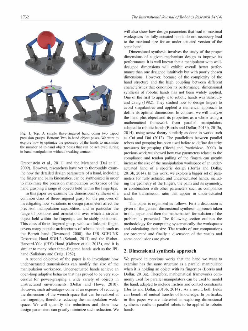
Fig. 1. Top: A simple three-fingered hand doing two tripod
precision grasps. Bottom: Two in-hand object poses. We want to
explore how to optimize the geometry of the hands to maximize
the number of in-hand object poses that can be achieved during
in-hand manipulation without breaking contact.
1732 The International Journal of Robotics Research 34(14)
Indeed, the field of parallel manipulators has extensively
explored dimensional synthesis. Jean-Pierre Merlet defines
four different main approaches (Merlet, 2006a).
1. The atlas approach. This reduces the number of para-
meters to a small set and then it defines measurements
for all the combinations, showing the results as a
graphical representation where the optimal can be
chosen visually.
2. The cost function approach. This defines a cost func-
tion with a weighted sum of indexes that need to be
optimized, finding the design parameters that optimize
it using numerical techniques.
3. The exact synthesis approach. This optimizes for a
particular task, defined as a set of poses, velocities,
and accelerations. It solves analytically the design
parameters whose workspace includes the prescribed
poses.
4. The parameter space approach. This defines a space
where each dimension represents a design parameter.
Each design requirement corresponds to an area of
such space, and several requirement areas can be inter-
sected. The optimal geometry search, for a solution
that holds several requirements, can be done searching
only in the intersection.
The second approach is by far the most widely used in
the context of parallel manipulators, but often with a single
index optimization that does not take into account other
requirements (Merlet, 2006a; Tsai, 1999). Defining a
weighted sum of different indexes is often arbitrary and,
therefore, their results can be misleading (Das and Dennis,
1997). In addition, it has already been proved in the context
of parallel robots that manipulability indexes or condition
numbers do not define a proper measure of quality (Merlet,
2006b), and therefore any cost function relying on those
indexes can be also misleading. In conclusion, although the
cost function approach could be directly applied to robotic
hands, it does not seem promising because, in addition to
the mentioned drawbacks, for robotic hands we need to
consider additional restrictions such as contact friction con-
straints and fingers that can only push and not pull.
The third approach becomes unwieldy when dealing
with complex geometries. It has been applied for single-
finger design (Dai and Wang, 2007), and also for structures
that take into account several fingers (Simo-Serra et al.,
2012). However, it implies the resolution of very complex
systems of equations and solutions are optimal only for
very specific tasks that specify a discrete number of con-
figurations and velocities in the workspace.
The first approach allows the exploration of the entire
parameter space and therefore, it guarantees a global opti-
mum. However, the need of presenting results graphically
limits this approach to the exploration of only 2 or 3 para-
meters. The generalization of this concept leads to the
fourth approach, where several requirements can be
intersected.
For the present work, we suggest a combination of the
first and the fourth approach. We propose a novel graphical
representation of parameter spaces with more than three
dimensions as polygons with as many vertexes as para-
meters. Despite the simplicity of the approach, it allows
taking into account joint limits, friction cone conditions,
and avoidance of singularities, as the other approaches do.
As in all optimization methods, we need to establish
assumptions to reduce the parameter exploration space. In
our case, on the shape of the object we assume the normal
to the object surface at the contact points directed towards
the center of mass. That is valid for spheres, discs, and
other round objects, which are the most commonly grasped
with tripod grasps. We also fix the structure of links and
joint axis orientations. However, our results give insights to
a wide range of existing hand designs and our methods
could be easily applied to other designs. Finally, we focus
on the maximization of the size of the workspace, not its
shape, or its properties. Properties such as manipulability
can also be included, and are analyzed in the last section of
the paper.
In practice, a design process should take into consider-
ation combined criteria including grasping and workspace.
Nevertheless, this work is useful to show how optimal para-
meters for workspace size are significantly different from
parameters for other criteria. Indeed, we show how, if the
size of the workspace is ignored, particularly for under-
actuated hands, the resulting design could have a much-
reduced workspace that could greatly limit the versatility of
the designed hand.
3. Mathematical formulation
Consider the hand-plus-object system formed by the three-
fingered hand (with two-link fingers), the contact points,
and the object shown in Figures 1 and 2. Each finger i has
three rotational joints with axis zi1, zi2 and zi3 (zi2 k zi3 and
zi1? zi2) as shown in Figure 2, written with respect to a
fixed reference frame located at the palm, with angles of
rotation ui1, ui2, and ui3, respectively. The 0 angle config-
uration corresponds to a full opened hand with the fingers
equally spread around the palm. The position and orienta-
tion of the object with respect to the palm reference frame
are given by a position vector p 2 R3 of the center of mass
(CoM) of the object and a rotation matrix R 2 SO 3ð Þ,together forming the object local reference frame p,Rf g.Therefore, the object workspace is 6-dimensional. Given
the object pose, if the locations of the contact points in the
object reference frame are given by the position vectors ~ci,we can transform them to the global reference frame as
ci = p+R~ci ð1Þ
The total number of joints of the hand is m = 9. We rep-
resent each contact point on the object as three additional
passive joints, acting as a spherical joint that is free to
move. This is locally equivalent to the point contact with
Borras and Dollar 1733

friction contact model (Borras and Dollar, 2013a).
Therefore, the total number of joints of the hand-plus-
object system is m + 9. Let
q= u11, ::, u33ð ÞT ð2Þ
be the 9-dimensional vector of all the hand joint angles.
Any value of q determines a configuration of the hand, but
once the object is grasped, only six joint angles are indepen-
dent and determine the position of the object, and the rest
are determined by contact constraints, namely, the fingertip
contact points must remain in contact with the object at the
same contact points during the in-grasp manipulation.
In our approach, we will sample the position and orientation
space of the object. Each object pose determines the location
of the contact points through equation (1) that are used to solve
the inverse kinematics of each finger to obtain the correspond-
ing configuration of the hand. Details on how to solve the kine-
matics can be found in Borras and Dollar (2013b).
3.1 Fully actuated hand static equilibrium
equations
There are several approaches to define the matrix that maps
the joint velocities _q to the platform/object 6-dimensional
twist v (Tsai, 1999). Here we will use the theory of recipro-
cal screws using the framework presented in Borras and
Dollar (2014), that is based on a parallel robot framework
(Mohamed and Duffy, 1985). The matrix J is called the
Jacobian matrix of the system, and defines the linear rela-
tionship between the object twist and the velocities at the
joints as
Jv= _q ð3Þ
It is well known that the same matrix, transposed,
describes the mapping between external transmitted wrench
on the object and the torques exerted at the joints. Then, if
w is the total external 6-dimensional wrench acting on the
object, and t is the 9-dimensional vector of torques exerted
by each joint, we can write
� w= JT t ð4Þ
For the studied manipulator, the Jacobian is a 6× 9
matrix expressed as JT = � � � si1 si2 si3 � � �ð Þ, for i = 1, 2, 3,
where each column sij is the 6-dimensional jth wrench of
the finger i, and they are of the form
sij = gij, hij
� �ð5Þ
where gij corresponds to the force part of the wrench, and
hij the rotational-moment part.
Equation (4) defines the static equilibrium of the hand-
plus-object. From equations (4) and (5) we can rewrite the
fingertip forces with respect to the palm reference frame as
fi =X3
j = 1
tijgij, i = 1, 2, 3 ð6Þ
This fingertip force ignores the rotational part of the
wrenches (the moment) because with the point with friction
model, the moments are not transmitted to the object.
A configuration can only be considered inside the
manipulation workspace if it is in static equilibrium and
the corresponding fingertip forces are inside the friction
cones.
To check the friction cone conditions, we need some
information about the object. As we mentioned, we assume
the vector normal to the plane tangent to the surface of the
object at the contact normal to be directed towards the cen-
ter of mass, located at p. Therefore, it can be defined as
ni = p� ci, where ci is the contact point. The fingertip
force obtained in equation (6) is then inside the friction
cone if the projection on that normal vector nfi = nTi fi, and
the projection on the normal plane to the vector,?fi = jj Id� nin
Ti
� �fi jj satisfy
?fi�mnfi ð7Þ
where m is the coefficient of friction and is taken as 0.7 for
the executions.
Note that the formulation introduced so far is general
and can be applied to any hand following results in Borras
and Dollar (2014).
3.2 Under-actuated hand static equilibrium
equations
When using under-actuated fingers, there are more joints
than actuators. Many of the latest under-actuated hands use
tendon cables combined with compliant joints (Dollar and
Howe, 2010; Odhner et al., 2013) as in Figure 3 . For these
hands, we can model the transmission mechanism as a cou-
pling between the torques exerted by the joints actuated by
the same cable. Following results in Balasubramanian et al.
(2012), assuming that the tendon remains in contact with
the pulley, and the pulley radii are constant, such coupling
depends only on the ratio between the radii of the pulleys,
which we call the transmission ratio Tr.
Fig. 2. Model of the studied hand (top) with its design
parameters.
1734 The International Journal of Robotics Research 34(14)
We consider the second and third joints of each finger i
(with axes of rotation zi2 and zi3 in Figure 2) to be compliant
and actuated by the same pulling cable, as the two joints in
the finger of Figure 3, while the first joints of the fingers are
independently actuated. As shown in Figure 3, there is a
pulling cable and torsion springs in parallel with each of the
joints. Therefore, the torque exerted by each of these joints
can be decomposed into the torque exerted by the cable plus
the one done by the spring according to Hooke’s law:
tij =atij � kj uij � dj
� �ð8Þ
for each finger i = 1, 2, 3 and joint j = 2, 3, where kj . 0 is
the spring stiffness constant of the jth joint spring in each
finger i and dj is its resting configuration angle. Note that
k1 = 0. Note also that this expression can be expressed for
any hand with any tendon routing configuration.
For a given configuration and a given external applied
force, substituting (8) into the system in (4) leads to a linear
system where the unknowns are the nine actuation torques
� w= JT at + JT ct ð9Þ
where we have split the vector of torques into the actuation
torques at = atij
� �and the compliant torques
ct = �kj uij � dj
� �� �. As the actuation torques exerted by
the same cable only depend on the radius of the pulley,
they are proportional, and we can write ati3 = Trati2,
where Tr is the ratio between the radius of the third joint
pulley and the radius of the second joint pulley. Thus, we
can rewrite at as a 6-dimensional vector, and the above
system can be rewritten as
� w= JTa
at + JT ct ð10Þ
where JTa is a 6× 6 matrix obtained from JT combining the
columns as
JTa = � � � , si1, si2 + Trsi3, � � �ð Þ ð11Þ
Note that a solution of the system would represent a
valid configuration only if the cables were exerting a posi-
tive force. Depending on the routing of the cable, the ten-
dons always exert torque of the same sign; in this case, we
choose it to be positive.
In conclusion, when computing the workspace, we con-
sider a configuration to be inside the kinematic workspace
if it satisfies the following conditions.
1. The position and orientation of the object lead to a real
inverse kinematic solution.
2. The flexion finger joint angles are between 0 and 908.
3. The angle between the vectors ci � bi (following the
contact phalange) and the vector normal to the object
surface at the contact point is larger than 120�. We
consider this restriction because we are approximating
a rolling contact with a point contact, which only holds
locally, i.e., close to a chosen home configuration.
If all the joints are actuated, as in a fully actuated hand, the
static equilibrium equations in (4) have a 3-dimensional solu-
tion, and therefore, in a generic configuration, there is always
a solution that satisfies (7), assuming that we don’t limit the
actuation torques values. Therefore, all the configurations in
the kinematic workspace are theoretically part of the manipula-
tion workspace of the fully actuated version of the hand.
On the contrary, for the under-actuated version of the
hand, only a 0-dimensional solution of the static equili-
brium equations exists. Therefore, not all the configura-
tions in the kinematic workspace will be feasible. In other
words, in addition to the previous conditions, a configura-
tion is considered to be inside the manipulation workspace
of the under-actuated version of the hand if:
(a) it satisfies static equilibrium equations (10);
(b) the corresponding fingertip forces are inside the fric-
tion cones; and
(c) the actuation torques exerted by the tendon cables are
positive.
To obtain the overall maximum without falling into
local minima, we explore all possible configurations of the
hand-plus-object according to a given 6-dimensional dis-
cretized space of poses for the object (Figure 4), and for a
given external applied force. If for a configuration and a
force there is a solution of the static equilibrium equations
that satisfy the conditions (a) to (c) listed above, it means
that the configuration belongs to the manipulation work-
space of the under-actuated hand. Also, we simplify further
the problem considering only forces of magnitude 0. In this
situation, the actuation torques are still not zero as they
need to compensate for the force done by the compliant
joints, and results are valid for external forces of small
magnitudes in any possible direction.
Finally, we want to note that we do not study how to
control the hand to move from one configuration to another.
However, transitions from one point to another are possible,
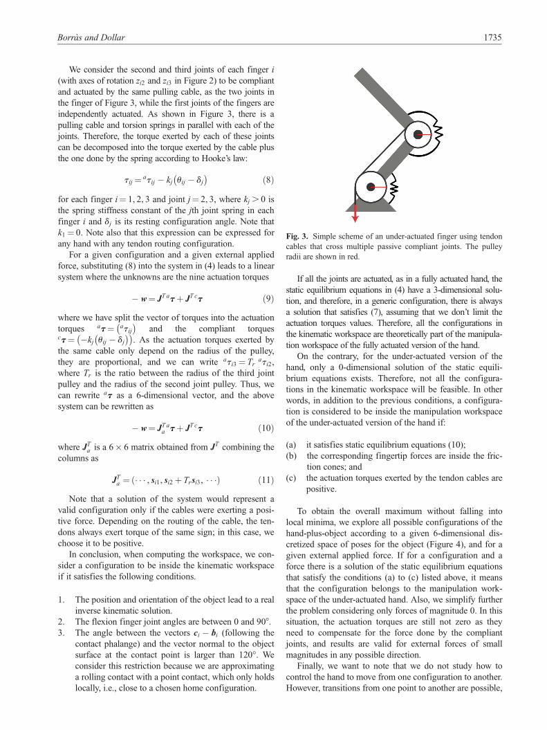
Fig. 3. Simple scheme of an under-actuated finger using tendon
cables that cross multiple passive compliant joints. The pulley
radii are shown in red.
Borras and Dollar 1735

and could be obtained using an energy minimization prob-
lem as suggested in Odhner and Dollar (2011).
For the simulations in this work, we do not limit the tor-
que the motors can exert, but we do discard singular con-
figurations. These are configurations in which the Jacobian
matrix is very close to being rank deficient, and we cannot
solve the linear system in (10). In the field of parallel
robots, singularities have been widely studied, for details,
see Gosselin and Angeles (1990). For configurations closer
to a singularity, the magnitude of the torques can grow infi-
nitely and thus, in practice, the size of the manipulation
workspace can be limited by this factor. However, for fully
actuated hands usually a solution can be found with mini-
mized torques, and for under-actuated hands we will see
how we can reduce the exerted torques by modifying some
of the stiffness constants without modifying the direction
of the fingertip forces, and thus, without modifying the size
of the manipulation workspace.
4. Methodology
We distinguish two types of parameters: geometric para-
meters and manipulation parameters. The first group
defines the geometry of the hand and they are sufficient to
compute the kinematic workspace defined by just solving
the kinematics. This is enough to compute the workspace
of fully actuated hands. The second group is related to
compliance and transmission ratios parameters that are nec-
essary to compute the workspace of the under-actuated
hand.
To normalize the results across different hand sizes we
consider a fixed finger length of 1, and we define ratios of
parameters for this fixed finger length (Figure 2 and
Table 1). (Note, this paper omits the units because they are
not relevant for the method. By default, consider ISU:
meter (m), radian (rad) and Newton (N). The results are
scalable to any hand size desired.). The parameters
described in Table 1 are:
1. Pr Ratio between the diameter of the palm and the
length of the finger.
2. Or Ratio between the diameter of the object and the
length of the finger.
3. DPr = d=l Ratio between distal (d) and proximal (l)
link lengths. Because we fix d + l = 1, it is equivalent
to give values to the proximal link length l instead.
4. a : Angle (in rad) of polar coordinates for the palm
finger attachments a2 and a3 (see Figure 2).
5. b: Angle (in rad) of polar coordinates for the contact
points c2 and c3 (see Figure 2).
The two angle parameters encode the symmetry of the
hand, being symmetric with respect to all fingers when
a = b = p=3. Note that the geometrical parameters above
are enough to solve the kinematics.
The manipulation parameters are:
(a) Kr = k3=k2 stiffness constants ratio between the third
and the second joint springs;
(b) k2 stiffness constant of second joint springs;
(c) Tr transmission ratio, i.e., ratio between the pullies
radii of the third and second joints;
(d) d2 and d3: resting configurations of the springs.
We are considering cables pulling in an active close
mechanism, hence we set the two resting configuration
angles of the springs to 0, so that the resting configuration is
the hand opened. We also consider a null external force.
Then, we can rewrite the static equilibrium equations (10) as
� k2 JTK1 0 0
0 K2 0
0 0 K3
0@
1Aq= JT
aat ð12Þ
where Ki are the stiffness matrices of each finger and have
the form
Ki =0 0 0
0 1 0
0 0 Kr
0@
1A
and q is the vector of joint angles defined in (2).
From system (12) we can state that the actuation torquesat are proportional to k2. In addition, from equation (6) we
can write the fingertip force as
fi = ti1gi1 + ti2gi2 + ti3gi3 =
(ati1gi1 + ati2 + k2ui2
� �gi2 + Tr
ati2 + Krk2ui3
� �gi3 =
ati1gi1 + ati2 gi2 + Trgi3ð Þ+ k2 ui2gi2 + Krui3gi3ð Þð13Þ
As before, we concluded that the actuation torques, ati1
and ati2, are all proportional to k2, the last expression in
(13) is proportional to k2, and so, we can conclude that fin-
gertip forces are proportional to k2. In other words, when
no external force is considered, the parameter k2 only modi-
fies the magnitude of the fingertip forces, but not their
direction. Note that this is not true under the presence of an
external force, but in our case it allows us to remove k2
from the parameter space. Results are orientative and valid
for small external forces. In addition, the value of k2 can
also be used to reduce the mangitude of the actuation
Table 1. Design parameters.
Parameter Def. Range
Pr Dp=f 1, 2:5ð ÞDPr d=l 0:4, 2:3ð ÞOr Do=f 0:3, 1:5ð Þa p=6,p=2ð Þb p=6,p=2ð ÞKr k3=k2 0:5, 4ð ÞTr r3=r2 0:6, 1:2ð Þ
1736 The International Journal of Robotics Research 34(14)
torques. As we are interested in small actuation torques, we
set k2 = 0:5.
4.1 Discretization of the workspace
We consider a discretization of the workspace in position
and orientation. Each kinematic workspace will be a subset
of all the configurations and each manipulation workspace
of the under-actuated hand version a subset of the kine-
matic workspace. The chosen discretization is shown in
Table 2 and Figure 4. The step in x and z is 0.05 and the
positions are distributed radially as in Figure 4(b). (Again,
we omit units because it is all scalable according to the size
of the finger. Using the ISU, that would be 0.05 m for a
1 m finger.) The orientations are sets of rotation matrices
R= i, j, kð Þ, where vectors k (in blue in the figure) repre-
sent the vector normal to the plane formed by the three
contact points, and they are distributed around a sphere that
represents the span of orientations around OX and OY
(Figure 4(a)). For the discretization used, a total of 4,879
positions are combined with 305 orientations at each posi-
tion, leading to 1, 488, 095 object poses. The range of
motion considered for each pose parameter is shown in
Table 2.
We define the size of the workspace by simply counting
the number of configuraitons inside the workspace. As we
are only interested in choosing the parameters with bigger
workspace, we do not need to define a proper volume, but
just compare between different sizes.
We are looking for the biggest workspace, and therefore
we want to know if the discretization of our workspace is
affecting at the order in size of different computed hand
workspaces. To study this, we computed the size of the
kinematic workspaces of 20 well-distributed different geo-
metries of hands using six different discretizations,
described in the table in Figure 5 (top). Each discretization
increases the number of object poses, with number 6 being
the most accurate one with a total of more than 29 million
poses.
For each discretization, we computed the size of each
workspace and divided its value by the biggest one, so that
for each discretization, we have a list of sizes for each of
the 20 hands that range from 0 to 1:
disci =iws1, . . . , iws20
� �, i = 1, . . . , 6
Note that in each list disci at least one value is 1. The
values obtained for the most accurate discretization, disc6,
were the closest to the truth, and so, we compared all the
rest to them:
disci =iws1 � 6ws1, . . . , iws1 � 6ws20
� �, i = 1, . . . , 5
Figure 5 (bottom) shows the mean values of the above
values for each discretization. In other words, the bars rep-
resent the mean differences in size for all of the 20 hands.
We can see that for the used discretization, the obtained
erros are, at the maximum, only 0.03 (that is, the workspace
sizes are 3% different than sizes computed with discretiza-
tion number 6), and the mean difference is only 1% (indi-
cated by the dashed line in the graphic). Therefore, for the
results shown in the next section, we always consider as
optimal the best 2% sizes.
5. Results
We considered first the full actuated hand and we swept all
the geometric parameters: palm, distal–proximal ratio, and
the size of the object. The length of the fingers is fixed,
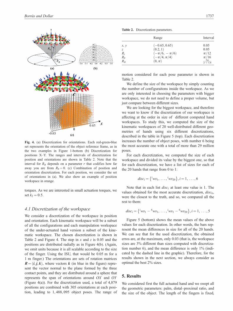
Fig. 4. (a) Discretization for orientations. Each red-green-blue
set represents the orientation of the object reference frame, as in
the two examples in Figure 1-bottom (b) Discretization for
positions X–Y. The ranges and intervals of discretization for
position and orientations are shown in Table 2. Note that the
interval for Rf depends on a parameter r that codifies how far
away you are from Ru = 0. (c) Combination of position and
orientation discretization. For each position, we consider the set
of orientations in (a). We also show an example of position
workspace in orange.
Table 2. Discretization parameters.
Range Interval
x, y �0:65, 0:65ð Þ 0:05z 0:2, 1ð Þ 0:05Rz �p=6, � p=6ð Þ p=12Ru �p=4,p=4ð Þ p=16Rf 0,pð Þ 2p
r + 1ð Þ6
Borras and Dollar 1737

l + d = 1; therefore, the range shown for DPr corresponds
to lengths of the proximal link from 0:3 to 0:7.
Using the discretization selected in the previous section,
we checked the 1, 488, 095 possible configurations for each
combination of geometric design parameters for the ranges
shown in the Table 1. The obtained 2% maximum size of
the workspaces for a fully actuated hand is 124, 451 and
122,914 configurations. The maximum sizes are obtained
with the geometrical parameters
Pr = 1:5, l = 0:4, Or = 0:3f g, andPr = 1:25, l = 0:4, Or = 0:3f g
ð14Þ
respectively.
Figure 6 (top) shows the evolution of workspace size
when the geometric parameters change for different object
sizes. The color bar on the left represents the evolution of
the fully actuated workspace size, from the biggest size
obtained with dark color (124,451 configurations) to 0 con-
figurations (light color). The figure shows that, when the
object size increases, we can observe that palm size
increases accordingly, whereas the optimal proximal link
length slightly decreases.
We performed a similar simulation computing the size
of workspaces for the under-actuated hand defined in the
previous section, using the sweeping of the same geometric
parameters, and adding the sweeping of Tr from 0.6 to 1.2,
and fixing Kr = 4. Figure 6 (bottom) shows the results fol-
lowing the color bar on the right from the maximum
obtained size in dark color (52,441) to 0 with light color.
From Figure 6 we can observe that the optimal trends
for palm-object sizes are similar for fully and under-
actuated hands. However, the sizes of the fully actuated
hand workspaces are big consistently for wide ranges of
the proximal link length, while the proximal link length
needs to be close to 0.5 for under-actuated hands, indepen-
dently of the transmission ratio used.
Table 3 shows the results of the 10 best fully actuated
workspaces. The table contains also the maximal under-
actuated hand workspace that can be achieved with each
corresponding geometrical parameter and the manipulation
parameters needed to obtain it. The last column shows the
percentage of the fully actuated hand workspace that is part
of the under-actuated hand workspace. We can see that
using under-actuation implies a reduction between 80 to
50% of the workspace. However, our computations indicate
that the lost configurations are always located at the border,
away from the inside/central configurations, which are in
practice most likely to be part of feasible workspace when
taking into account rolling contacts and motor torque
limits.
Table 3 also tells us that the biggest size of under-
actuated hand workspace does not coincide with the opti-
mal for the fully actuated hand. Indeed, with the optimum
geometric parameters (Pr = 1:5, l = 0:4, Or = 0:3) the max-
imum feasible workspace that can be obtained with under-
actuation is only 36, 035 configurations, with T r = 0:8,
but the size of the biggest under-actuated workspace is
45:5% bigger. This is an important result, because it shows
us that for an optimal size of workspace for an under-
actuated hand, it is not enough to use an optimal fully actu-
ated hand, but an independent optimization needs to be
computed.
Therefore, we run an independent simulation by sweep-
ing all the parameters in the ranges shown in the Table 1,
including the stiffness ratio, but fixing a and b at p=3 (for
a symmetric hand with respect to each finger), to compute
the sizes of the under-actuated hand workspaces.
We computed a total of 6,125 workspaces. The 2% max-
imum obtained workspaces for the under-actuated hand
contain 52, 441 and 52, 321 configurations and they are
obtained with the parameters
fPr = 1:25, l = 0:5, Or = 0:3, Kr = 4, Tr = 0:8g andfPr = 1:25, l = 0:5, Or = 0:3, Kr = 4, Tr = 0:9g
ð15Þ
respectively.
The results are plotted in Figure 7. To be able to plot the
five dimensions of the parameter space, we plot a polygon
for each set of data (parameters, size), where each polygon
vertex corresponds to the value of the parameter and the
color code represents the size of the workspace, compared
to the biggest one, and thus, ranging from 0 to 100. In
additon to the five parameters, each polygon has two extra
vertexes that correspond to the coordinates x and z of the
centroid of the computed workspace.
Fig. 5. Table with different workspace discretizations and the
mean errors obtained when computing the size of the workspaces
compared to the sizes obtained using the sixth optimization (with
29 million configurations).
1738 The International Journal of Robotics Research 34(14)

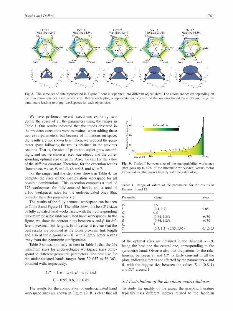
As the object size is not a proper hand parameter,
Figure 8 shows the same data set, plotting separetely the
results for different sizes of the object, where the colors
range again from 0 to 100, but they are scaled using the
biggest size obtained for each object. The maximum work-
space size in each plot compared to the overall maximal
workspace is indicated at the top of each plot. Below each
plot, we show a representation of the hand design that has
the biggest workspace.
From Figure 8 we can observe several trends. For
instance, the maximum size is always obtained at the maxi-
mum stiffness ratio. We analyze in depth this relationship
in section ‘On the stiffness constant’. Also, the optimal size
of palm and object grow proportionally, at a ratio fairly
constant of Pr � Or’1, that is, the radii difference between
palm and object is about half of the length of the finger.
The section ‘On the palm size’ will study this trend in
detail.
5.1 On the stiffness constant
From the above simulation, we observed that the biggest
workspace of the under-actuated hand is always obtained
for the maximum stiffnes ratio possible.
Fig. 6. Contour plots between proximal link length and palm size for growing size of the held object. The first row shows results of a
fully actuated hand, following the first color bar code whose maximum value is 124,451 configurations. The rest of the rows show
results for the under-actuated hand for the same object sizes and different values of transmission ratio from 0.6 to 1.1, following the
second color bar code that reaches a maximum value in blue of 52,441 configurations.
Borras and Dollar 1739
To study this in detail we fixed all the parameters
except the stiffness ratio, to Pr = 1:2,DPr = 1,Or = 0:25,a = 0:87,b = 1:04 and Tr = 0:8. Then, we computed the
size of fully actuated hand workspace and the size of the
manipulation workspace of the under-actuated hand for
growing values of Kr, from 4 to 70.
We found that the size of the manipulation workspaces of
the under-actuated hand increases for bigger stiffness ratios,
up to a maximum value which, for this particular design, was
close to 50% of the workspace of the fully actuated hand.
However, the magnitudes of the necessary actuation torques
to obtain static equilibrium also grew.
Figure 9 shows the relationship between the median
motor torque accross the workspace with the size of the
workspace for different values of stiffness ratios. It can be
observed how above Kr = 8, the size of the manipulation
workspace can only grow a maximum of 2% more, but the
values of the median actuation torques grow exponentially.
Therefore, we need to chose a stiffness ratio as big as pos-
sible in accordance with the limiation of the motors of our
hand.
We have also analyzed the location of the new config-
urations when the stiffness ratio grows. Our results indi-
cated that the new configurations are always at the border
of the workspace. In other words, when reducing the stiff-
ness ratio to save motor enery, we will be only losing
configurations away from the center position.
Representations of the shape of the manipulation work-
space can be found in the section ‘Distribution of the
Jacobian matrix indexes’.
5.2 On the palm size
From the results in Figure 7 we stated that the optimal rela-
tionship between size of palm and object was Pr � Or’1,
that is, the difference between palm and object diameter
similar to the length of the fingers. We study this relation-
ship in more detail in Figure 10, where we can see the evo-
lution of the contour plots between transmittion ratio vs.
proximal link length for different sizes of palm and object
for the under-actuated hand.
Looking at the axes Pr � Or, we can see how the palm
size increases in accordance with the object size, as we
observed before. In addition, the optimal values are consis-
tently obtained around a DPr = 1, which corresponds to
the proximal link length of 0.5. The transmission ratio
slightly shifts from high values to lower values when the
palm grows from small to big.
5.3 On the symmetry of the palm and the grasp
We performed a second execution, adding the parameters a
and b to study the effect on the symmetry of the palm.
Note that the variation of a changes the symmetry of the
palm, whereas b changes the symmetry of the grasping
points.
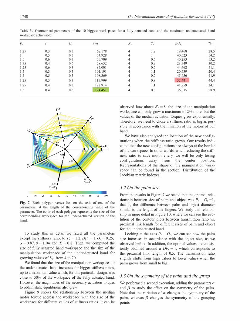
Table 3. Geometrical parameters of the 10 biggest workspaces for a fully actuated hand and the maximum underactuated hand
workspace achievable.
Pr l Or F-A Kr Tr U-A %
1.25 0.3 0.3 68,178 4 1.2 19,468 28.51. 0.5 0.3 74,928 4 1 40,623 54.21.5 0.6 0.3 75,709 4 0.6 40,253 53.21.75 0.4 0.6 78,652 4 0.9 23,749 30.21.25 0.6 0.3 87,001 4 0.7 44,462 51.11.5 0.3 0.3 101,191 4 1.1 20,639 20.41.5 0.5 0.3 108,369 4 0.7 45,456 41.9
1.25 0.5 0.3 117,999 4 0.8 52,441 44.4
1.25 0.4 0.3 122,914 4 1.1 41,859 34.1
1.5 0.4 0.3 124,451 4 0.8 36,035 28.9
Fig. 7. Each polygon vertex lies on the axis of one of the
parameters, at the length of the corresponding value of the
parameter. The color of each polygon represents the size of the
corresponding workspace for the under-actuated version of the
hand.
1740 The International Journal of Robotics Research 34(14)
We have perfomed several executions exploring ran-
domly the space of all the parameters using the ranges in
Table 1. Our results indicated that the trends observed in
the previous executions were mantained when adding these
two extra parameters, but because of limitations on space,
the results are not shown here. Then, we reduced the para-
meter space following the results obtained in the previous
sections. That is, the size of palm and object grow accord-
ingly, and so, we chose a fixed size object, and the corre-
sponding optimal size of palm. Also, we can fix the value
of the stiffness constant. Therefore, for the execution results
shown next, we set Pr = 1:5, Or = 0:5, and Kr = 7.
For the ranges and the step sizes shown in Table 4, we
compute the sizes of the manipulation workspace for all
possible combinations. This execution computes a total of
175 workspaces for fully actuated hands, and a total of
2,100 workpaces sizes for the under-actuated ones (that
consider the extra parameter Tr).
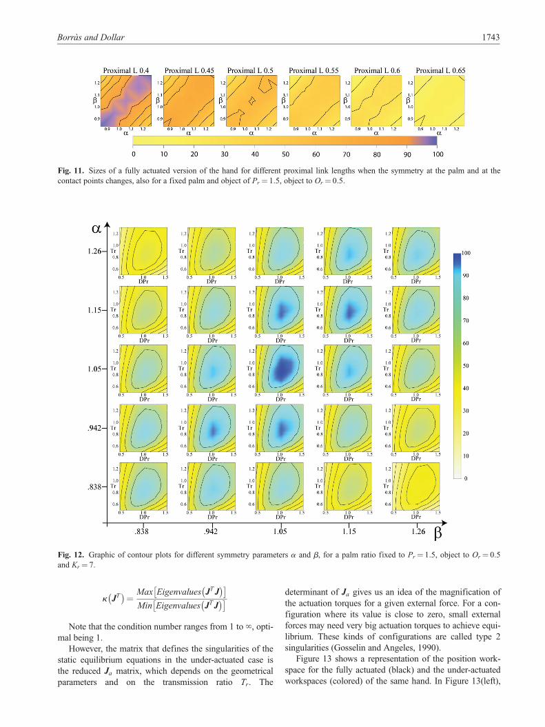
The results of the fully actuated workspace can be seen
in Table 5 and Figure 11. The table shows the best 2% sizes
of fully actuated hand workspaces, with their corresponding
maximum possible under-actuated hand workspaces. In the
figure, we show the contour plots between a and b for dif-
ferent proximal link lengths. In this case, it is clear that the
best results are obtained at the lower proximal link length
and also at the diagonal a = b, with slightly better results
away from the symmetric configuraiton.
Table 5 shows, similarly as seen in Table 3, that the 2%
maximum sizes for under-actuated workspace sizes corre-
spond to different geometric parameters. The best size for
the under-actuated hands ranges from 39, 057 to 38, 363,
obtained with, respectively,
DPr = 1,a = p=3,b = p=3 and
Tr = 0:95, 0:8, 0:9, 0:85
The results for the computation of under-actuated hand
workspace sizes are shown in Figure 12. It is clear that all
of the optimal sizes are obtained in the diagonal a = b,
being the best one the central one, corresponding to the
symmetric hand. Observe also that the pattern for the rela-
tionship betweeen Tr and DPr is fairly constant in all the
plots, indicating that is not affected by the parameters a and
b, with the biggest size between the values Tr 2 0:8, 1ð Þand DPr around 1.
5.4 Distribution of the Jacobian matrix indexes
To study the quality of the grasp, the grasping literature
typically uses different indexes related to the Jacobian
Fig. 8. The same set of data represented in Figure 7 here is separated into different object sizes. The colors are scaled depending on
the maximum size for each object size. Below each plot, a representation is given of the under-actuated hand design using the
parameters leading to bigger workspaces for each object size.
Fig. 9. Tradeoff between size of the manipulability workspace
(that goes up to 49% of the kinematic workspace) versus motor
torque values, that grows linearly with the value of Kr.
Table 4. Range of values of the parameters for the results in
Figures 11 and 12.
Parameter Range Step
Pr 1:5 �l 0:4, 0:7ð Þ 0:05Or 0:5 �a 0:84, 1:25ð Þ p=30b 0:84, 1:25ð Þ p=30Kr 7 �Tr 0:5, 1:3ð Þ, 0:85, 1:05ð Þ 0:1,0:05
Borras and Dollar 1741

matrix of the system. Sometimes this relates only to the
Grasp matrix, and sometimes it relates to the combination
of both the Grasp matrix and the hand Jacobian (Shimoga,
1996). From our analysis, we want to study how these val-
ues look for one hand plus object with optimal workspace
size. We have chosen the parameters
Pr = 1:5,DPr = 1,Or = 0:5,a = p=3,b = p=3,
Kr = 7, Tr = 0:9,
that lead to a fully actuated hand with 83, 566 configura-
tions workspace and a under-actuated version with 38, 749
(that is a 46.4%).
The most widely used index is the condition number of
the matrix JT (Merlet, 2006b), which is valid for both
under-actuated and fully actuated hands, and is defined as
Fig. 10. Evolution of the size of the workspaces for under-actuated hands. We show contour plots between transmission ratio and
proximal link lengths across different palm and object sizes, with the rest of the parameters fixed to a = b = p=3 and Kr = 4.
Table 5. Best fully actuated workspaces for Pr = 1:5 and Or = 0:5.
Prox L a b F-A Tr U-A
0.45 1.25 1.24 93908 0.9 339610.45 0.84 0.84 94355 0.9 323870.4 1.26 1.24 94827 1. 283610.4 0.84 0.84 95097 0.95 26558
1742 The International Journal of Robotics Research 34(14)
k JT� �
=Max Eigenvalues JTJ
� �� �
Min Eigenvalues JTJ� �� �
Note that the condition number ranges from 1 to ‘, opti-
mal being 1.
However, the matrix that defines the singularities of the
static equilibrium equations in the under-actuated case is
the reduced Ja matrix, which depends on the geometrical
parameters and on the transmission ratio Tr. The
determinant of Ja gives us an idea of the magnification of
the actuation torques for a given external force. For a con-
figuration where its value is close to zero, small external
forces may need very big actuation torques to achieve equi-
librium. These kinds of configurations are called type 2
singularities (Gosselin and Angeles, 1990).
Figure 13 shows a representation of the position work-
space for the fully actuated (black) and the under-actuated
workspaces (colored) of the same hand. In Figure 13(left),
Fig. 11. Sizes of a fully actuated version of the hand for different proximal link lengths when the symmetry at the palm and at the
contact points changes, also for a fixed palm and object of Pr = 1:5, object to Or = 0:5:
Fig. 12. Graphic of contour plots for different symmetry parameters a and b, for a palm ratio fixed to Pr = 1:5, object to Or = 0:5and Kr = 7.
Borras and Dollar 1743

each dot color represents the minimum value of Det Jað Þ in
all the orientations achievable from the dot position. In
Figure 13(right), each dot color represents the median value
of the condition number of JT in all the orientations achiev-
able from the dot position. The bottom (right) figure shows
a piece of the fully actuated hand workspace, bordering in
black the positions that are also inside the under-actuated
workspace.
We can observe that the determinant of the matrix Ja is
bigger than 0.5 in almost all the workspace, being closer to
singularity at the border of the workspace. Further analysis
is needed to know where the second type of singularities is
located (Gosselin and Angeles, 1990), but preliminary
results show that the more optimal workspaces are those
where these type of singularities occur outside the reach-
able workspace.
We can also see in Figure 13 (bottom right) that the con-
figurations that belong to the under-actuated workspace are
the ones with lower condition number.
6. Conclusions
This work uses a framework for robotic hands inspired in
the parallel robots literature that computes the manipulation
workspace of a hand-plus-object system. This allows us to
explore the space of design parameters to find the hand
geometry that maximizes the size of the manipulation
workspace.
Our computations assume that the normals to the object
surface at the contact points are directed towards the center
of mass. This covers round shapes including spherical and
disk objects, which are the most commonly grasped with
the tripod grasp. In addition, we modeled the contact points
using the point with friction model, and thus, may not be
accurate away from the initial central position
px, py
� �= 0, 0ð Þ. To take that into account, we impose a
minimum angle of 120� between the normal to the surface
of the object at the contact point and the contact phalange.
Without taking into account the limitations on the
motors, we have observed that using under-actuation can
decrease the size of the manipulation workspace signifi-
cantly up to 80%. However, an optimal choice of the
under-actuation parameters can lead to a reduction of only
50% of the fully actuated hand workspace. More impor-
tantly, the 50% of the workspace that belongs to the under-
actuated hand workspace is always located at the center of
the object with respect to the hand, which are the most rele-
vant in practice.
Our design parameters exploration has shown several
additional interesting results. The diameter of the palm and
the diameter of the object are optimal when Pr � Or’1,
which means that the radii difference is about half of the
length of the finger. Note that for Pr = Or the fingers are in
a singularity at any central configuration px, py
� �= 0, 0ð Þ,
because the fingertip lies in the same x, yð Þ coordinates that
the base of the finger, allowing the rotation of the first joint
Fig. 13. Evolution of the determinant of the Jacobian matrix and the condition number for the workspace of a hand with parameters
Pr � 1:5, DPr = 1, Or = 0:5, a = p=3, b = p=3, Kr = 7, and Tr = 0:9.
1744 The International Journal of Robotics Research 34(14)
without modifying the location of the fingertip. Therefore,
it makes sense that the optimum is as far away as possible
from being in a singular configuration at the center of the
workspace, without being at a distance that disables mobi-
lity. Future work will study if such results are valid when
using the antropomorphic adbduction/adduction axis
instead of the vertial one in the fingers. However, for all the
existing robotic hands using the verital axis, the design of
the palm should have a diameter equal to the mean size of
object sizes we want to manipulate plus 1, so that they work
as well as possible with a wide range of object sizes.
Our results also show that the distal–proximal ratio
seems to be optimal when it is close to 1 (for under-actau-
ted) or slightly bigger than 1 (for fully actuated). The ratios
that are usually seen in most of two-link finger hands are
smaller than 1, meaning a shorter distal link. This is
because dimensional synthesis applied to single fingers
shows optimal conditioning at 0.7071 (Salisbury and
Craig, 1982), whereas Yoshikawa (1985) obtained optimal
manipulability and finger workspace volume at a ratio of 1.
However, these are results optimizing single fingers, and
not the workspace obtained with the combination of all of
them. It was expected that our results could indicate
slightly different results to optimize manipulation work-
space size. Note that if you consider a typical three-link
anthropomorphic finger with the distal joint locked, the
ratio between the two distal links and the proximal is closer
or even slightly bigger than 1. This indicates that the tripod
grasp with the antropomorphic three-linked fingers is
already optimized for workspace size, even if the distal
joint is kept fixed.
Our results also show that more optimal workspaces
with the tripod grasp are obtained for symmetric placement
of the fingers in the hand when the hand is under-actuated.
Regardless, we have seen that whatever the distribution on
the palm, it is best to use the same distribution for the grasp
contact points both for the under-actuated and for fully
actuated hands. However, this result may be different if we
change our assumption on the normal to the object surface
pointing towards the center of mass.
We have also shown that, for under-actuated hands,
increasing the finger stiffness ratio also increases the work-
space, at the cost of requiring larger actuation torques.
The optimal transmission ratios were found around 0.9,
decreasing slightly for bigger palm sizes independently of
the distal–proximal ratio.
The results presented in this paper are valid for the stud-
ied three-fingered hand structure using a fully actuated
hand versus an under-actuated version of the same hand
design. More generally, we can state that the optimal
dimensions to obtain big manipulation workspaces are dif-
ferent from others obtained optimizing a single grasp. For
instance, for manipulation workspaces, robotic hands seem
to need bigger distal–proximal ratios and bigger palms than
the ones seen in commercial hands such as the Barret hand
or the Schunk SDH hand. Additional analysis would be
needed to extend these results to other hand configurations,
including allowing the thumb to have a different geometry
as well as the analysis of three link fingers as in anthropo-
morphic configurations.
Optimal design for robotic hands is a challenging prob-
lem where many considerations need to be taken into
account. A design process usually involves optimization of
several criteria. We have shown that manipulation work-
space size is a relevant criterion to consider, particularly for
under-actuated hands, to avoid significant reductions of
workspace that can greatly limit the versatility of the final
hand design.
Funding
This work was supported in part by a grant from the National
Science Foundation, grant NSF IIS-0953856.
References
Balasubramanian R, Belter J and Dollar A (2012) Disturbance
response of two-link underactuated serial-link chains. Journal
of Mechanisms and Robotics 4: 021013.
Bicchi A and Prattichizzo D (2000) Manipulability of cooperat-
ing robots with unactuated joints and closed-chain mechan-
isms. IEEE Transactions on Robotics and Automation 16:
336–345.
Borras J and Dollar A (2013a) Framework comparison between a
multifingered hand and a parallel manipulator. In: Computa-
tional kinematics (eds F Thomas and AP Gracia), Barcelona,
Spain, pp. 219–227. Springer.
Borras J and Dollar A (2013b) A parallel robots framework to
study precision grasping and dexterous manipulation. In: IEEE
international conference on robotics and automation, Karls-
ruhe, Germany, pp. 1595–1601. IEEE.
Borras J and Dollar A (2014) Analyzing dexterous hands
using a parallel robots framework. Autonomous Robots 36:
169–180.
Bullock I, Ma R and Dollar A (2012a) A hand-centric classifica-
tion of human and robot dexterous manipulation. IEEE Trans-
actions on Haptics 6: 129–144.
Bullock I, Borras J and Dollar A (2012b) Assessing assumptions
in kinematic hand models: a review. In IEEE Ras/Embs Inter-
national conference on biomedical robotics and biomechatro-
nics, Rome, Italy, 24–27 June, pp. 139–146. IEEE.
Bullock I, Feix T and Dollar A (2013) Finding small, versatile sets
of human grasps to span common objects. In IEEE interna-
tional conference on robotics and automation, Karlsruhe, Ger-
many, 6–10 May, pp. 1068–1075. IEEE.
Butterfaß J, Grebenstein M, Liu H, et al. (2001) Dlr-Hand Ii: Next
generation of a dextrous robot hand. In IEEE international
conference on robotics and automation (ICRA), vol. 1, Seoul,
South Korea, 21–26 May, pp. 109–114. IEEE.
Butterfaß J, Hirzinger G, Knoch S, et al. (1998) Dlr’s multisensory
articulated hand. I. Hard-and software architecture. In Proceed-
ings of IEEE international conference on robotics and automa-
tion, vol. 3, Leuven, Belgium, 16–20 May, pp. 2081–2086.
IEEE.
Ciocarlie M and Allen P (2011) A constrained optimization
framework for compliant underactuated grasping. Mechanical
Sciences 2: 17–26.
Ciocarlie M, Hicks F and Stanford S (2013) Kinetic and dimen-
sional optimization for a tendon-driven gripper. In IEEE
Borras and Dollar 1745
international conference on robotics and automation, Karls-
ruhe, Germany, 6–10 May pp. 2751–2758. IEEE.
Cui L and Dai J (2012) Reciprocity-based singular value decom-
position for inverse kinematic analysis of the metamorphic multifin-
gered hand. Journal of Mechanisms and Robotics 4: 034502.
Cutkosky M (1989) On grasp choice, grasp models, and the
design of hands for manufacturing tasks. IEEE Transactions
on Robotics and Automation 5(3): 269–279.
Dai J and Wang D (2007) Geometric analysis and synthesis of the
metamorphic robotic hand. Journal of Mechanical Design 129:
1191.
Dai J, Wang D and Cui L (2009) Orientation and workspace anal-
ysis of the multifingered metamorphic hand—metahand. IEEE
Transactions on Robotics 25: 942–947.
Das I and Dennis J (1997) A closer look at drawbacks of mini-
mizing weighted sums of objectives for pareto set generation
in multicriteria optimization problems. Structural Optimization
14: 63–69.
Dollar A and Howe R (2010) The highly adaptive sdm hand:
design and performance evaluation. The International Journal
of Robotics Research 29: 585–597.
Gosselin C and Angeles J (1990) Singularity analysis of closed-
loop kinematic chains. IEEE Transactions on Robotics and
Automation 6: 281–290.
Grebenstein M, Albu-Schaffer A, Bahls T, et al. (2011) The Dlr
hand arm system. In: IEEE international conference on
robotics and automation (ICRA), Shanghai, China, 9–13 May,
pp. 3175–3182. IEEE.
Grebenstein M, Chalon M, Hirzinger G, et al. (2010) A method
for hand kinematics designers. 7 Billion perfect hands. In:
International conference on applied bionics and biomecha-
nics, Venice, Italy, 14–16 October.
Hammond Fl, Weisz J, De La Llera Kurth A, et al. (2012) Towards
a design optimization method for reducing the mechanical
complexity of underactuated robotic hands. In IEEE Interna-
tional conference on robotics and automation (ICRA), Saint
Paul, USA, 14–18 May, pp. 2843–2850. IEEE.
Jacobsen S, Iversen E, Knutti D, et al. (1986) Design of the utah/
mit dextrous hand. In: IEEE international conference on
robotics and automation, vol. 3, pp. 1520–1532. IEEE.
Kerr J and Roth B (1986) Analysis of multifingered hands. The
International Journal Of Robotics Research 4: 3–17.
Martell J and Gini G (2007) Robotic hands: Design review and
proposal of new design process. Proceedings of World Acad-
emy of Science, Engineering and Technology 20: 85–90.
Mason M and Salisbury J (1985) Robot Hands and the Mechanics
of Manipulation. Cambridge, MA: MIT Press.
Mason M, Srinivasa S and Vazquez A (2011) Generality and sim-
ple hands. Robotics Research. Springer Tracts in Advanced
Robotics. Berlin Heidelberg: Springer, pp. 345–361.
Matsuoka Y, Afshar P and Oh M (2006) On the design of robotic
hands for brain-machine interface. Neurosurgical Focus 20:
1–9.
Merlet J (2006a) Parallel Robots. 2nd ed. Dordrecht: pp.
301–320.
Merlet J (2006b) Jacobian, manipulability, condition number, and
accuracy of parallel robots. Journal of Mechanical Design 128:
199–206.
Michelman P (1998) Precision object manipulation with a multi-
fingered robot hand. IEEE Transactions on Robotics and Auto-
mation 14: 105–113.
Mohamed M and Duffy J (1985) A direct determination of the
instantaneous kinematics of fully parallel robot manipulators.
Journal of Mechanisms Transmissions and Automation in
Design 107: 226–229.
Odhner L and Dollar A (2011) Dexterous Manipulation with
underactuated elastic hands. In IEEE International conference
on robotics and automation, Shanghai, China, 9–13 May,
pp. 5254–5260. IEEE.
Odhner L, Jentoft L, Claffee M, et al. (2013) A compliant, under-
actuated hand for robust manipulation. The International Jour-
nal of Robotics Research 33: 736–752.
Okada T (1982) Computer control of multijointed finger system
for precise object-handling. IEEE Transactions on Systems,
Man and Cybernetics 12: 289–299.
Salisbury J and Craig J (1982) Articulated hands: Force control
and kinematic issues. The International Journal Of Robotics
Research 1: 4–17.
Schunk (2013) Schunk Dextrous Hand Sdh. Available at:
www.Schunk.Com (accessed 8 October 2015).
Shimoga K (1996) Robot grasp synthesis algorithms: A survey.
The International Journal of Robotics Research 15: 230–266.
Simo-Serra E, Perez-Gracia A, Moon H, et al. (2012) Kinematic
synthesis of multi-fingered robotic hands for finite and infini-
tesimal tasks. Latest Advances In Robot Kinematics. Dor-
drecht: Springer, pp. 173–180.
Townsend W (2000) The Barretthand grasper – programmably
flexible part handling and assembly. Industrial Robot: An
International Journal 27: 181–188.
Tsai L-W (1999) Robot Analysis. The Mechanics of Serial and
Parallel Manipulators. New York: John Wiley & Sons, Inc.
Yoshikawa T (1985) Manipulability of robotic mechanisms. The
International Journal of Robotics Research 4: 3–9.
1746 The International Journal of Robotics Research 34(14)