digitized automation for a changing world delta ac servo
TRANSCRIPT

Delta AC Servo Drive ASDA-A2-E Series
Digitized Automation for a Changing World
www.del taww.com

1
Introduction Delta's ASDA-A2-E, an advanced AC Servo Drive with an EtherCAT communication interface, complies with IEC61158 and IEC61800-7 and follows in the footsteps of the successful ASDA-A2 series. This advanced A2-E supports all the modes of the CoE device profile based on CiA402 and all command types of EtherCAT. It also features a built-in Safe Torque Off (STO) function which prevents torque energy from continuing to act upon a motor and averts accidents. In addition, A2-E offers an extension digital input port for a wide range of machinery automation fields. This series covers a power range from 400W to 7.5kW for 400V and 100W to 3kW for 220V.
ASDA-A2-E Series is your ideal servo drive to achieve high speed multi-axis synchronization applications.
Features■ Passes EtherCAT conformance test by EtherCAT Technology Group (ETG)■ Integrated Safe Torque Off (STO)* safety function according to the following standards: ■ IEC EN 61508 (SIL 2) ■ IEC 62016 (SIL 2) ■ ISO 13849-1 (Cat.3 PL=d)■ Supports absolute type and incremental type of servo motors ■ Supports touch probe function ■ Enabled with dedicated Digital Input (DI) on CN7 or the external encoder
*Note: STO function is not available for 200V 4.5kW ~ 7.5kW models
Applications
EtherCAT controllersThird party controllers Delta MH1 EtherCAT Series

2
Specifications of ASDA-A2-E_220 V Series ASDA-A2-E Series
100 W 200 W 400 W 750 W 1 kW 1.5 kW 2 kW 3 kW 4.5 kW 5.5 kW 7.5 kW01 02 04 07 10 15 20 30 45 55 75
PowerSupply
Phase / Voltage Three-phase / Single-phase 220 VAC Three-phase 220 VAC
Permissible Voltage Range Three-phase / Single-phase 200 ~ 230 VAC, -15%~10% Three-phase / 200 ~ 230 VAC, -15% ~ 10%Input Current (3 PH) Unit: Arms 0.8 1.11 1.86 3.66 4.68 6.33 8.76 9.83 17.5 19.4 26.3Input Current (1 PH) Unit: Arms 1 1.92 3.22 6.78 8.88 10.96 - - - - -
Continuous Output Current Unit: Arms 0.9 1.55 2.6 5.1 7.3 8.86 13.4 19.4 32.5 40 47.5Cooling Method Natural Air Circulation Fan Cooling
Encoder Resolution (Servo Drive Resolution) Incremental type: 20-bit; Absolute type: 17-bit
Control of Main Circuit SVPWM (Space Vector Pulse Width Modulation) ControlTuning Modes Auto / ManualDynamic Brake Non Built-in External
Position
Control
Mode
(CSP)
Command Source DS402 objectSmoothing Strategy Low-pass and P-curve filter
Electronic Gear Electronic gear N/M multiple N: 1 ~ 32767, M: 1 : 32767 (1/50 < N/M < 25600)Torque Limit Operation DS402 object
Feed Forward Compensation Internal parameters
Speed
Control
Mode
(CSV)
Speed Control Range*1 1:5000 1:3000Command Source External
Analog Signal DS402 object
Smoothing Strategy Low-pass and S-curve filterTorque Limit Operation Set by parameters Frequency Response
Characteristic Maximum 1 kHz
Speed Accuracy (at rated rotation speed)*2
0.01 % or less at 0 to 100 % load fluctuation0.01 % or less at 0℃ to 50℃ ambient temperature fluctuation
Feed Forward Compensation 0.01 % or less at ±10 % power fluctuation
Torque Control Mode(CST)
Command Source DS402 objectSmoothing Strategy Low-pass filter
Speed Limit Operation DS402 object
Digital
Inputs/
Outputs
Inputs
Servo on, Reset, Gain switching, Zero speed CLAMP, Command input reverse control, Command triggered, Speed/Torque limit enabled, Position command selection, Motor stop, Speed position selection, Position / Speed mode switching, Speed / Torque mode switching, Torque / Position mode switching, Emergency stop, Forward / Reverse inhibit limit, Reference “Home” sensor, Forward / Reverse operation torque limit, Move to “Home”, Electronic Cam (E-Cam), Forward / Reverse JOG input, Event trigger PR command, Electronic gear ratio (Numerator) selection* Please note that the above digital signals and inputs are available only for Non-DMCNET mode. In DMCNET mode, it is recommended to write digital inputs into the servo drives through DMCNET communication, and the digital inputs should be used for Emergency Stop, Forward / Reverse Inhibit limit and Reference "Home" sensor only.
Outputs
Encoder signal output (A, B, Z Line Driver and Z Open Collector )Servo ready, Servo on, At Zero speed, At Speed reached, At Positioning completed, At Torques limit, Servo alarm (Servo fault) activated, Electromagnetic brake control, Homing completed, Output overload warning, Servo warning activated, Position command overflow, Forward / Reverse software limit, Internal position command completed, Capture operation completed output., Motion control completed output., Master position of E-Cam (Electronic Cam)
Protective Functions
Overcurrent, Overvoltage, Undervoltage, Motor overheated, Regeneration error, Overload, Overspeed, Abnormal pulse control command, Excessive deviation, Encoder error, Adjustment error, Emergency stop activated, Reverse/ Forward limit switch error, Position excessive deviation, Serial communication error, Input power phase loss, Serial communication time out, short circuit protection of U, V, W, and CN1, CN2, CN3 terminals
Communication Interface USB / EtherCAT
Env
ironm
ent
Installation Site Indoor location (free from direct sunlight), no corrosive liquid and gas (kept away from oil mist, flammable gas, dust)Altitude Altitude 2000 m or lower above sea level
Atmospheric Pressure 86kPa ~ 106kPaOperating Temperature 0˚C ~ 55˚C (If operating temperature is above 45˚C, forced cooling will be required)Storage Temperature -20˚C ~ 65˚C
Humidity 0 ~ 90% RH (non-condensing)Vibration 9.80665 m/s2 (1 G) less than 20 Hz, 5.88 m/s2 (0.6 G) 20 ~ 50 HzIP Rating IP20
Power System TN System*3
Approvals IEC/EN 61800-5-1, UL 508C, C-tick
Footnote:*1 Rated rotation speed: When full load, speed ratio is defined as the minimum speed (the motor will not pause).*2 When command is rated rotation speed, the speed fluctuation rate is defined as: (Empty load rotation speed – Full load rotation speed) / Rated rotation speed*3 TN system: A power distribution system having one point directly earthed, the exposed conductive parts of the installation being connected to that point by a protective earth conductor.

3
Specifications of ASDA-A2-E_400 V SeriesASDA-A2-E Series
400 W 750 W 1 kW 1.5 kW 2 kW 3 kW 4.5 kW 5.5 kW 7.5 kW04 07 10 15 20 30 45 55 75
PowerSupply
Input Voltage 24 VDC, ±10%Input Current 0.43 A 1.18 A 1.66 AInput Power 10.32 W 28.2 W 39.85 W
Main Circuit Power
Permissible Voltage Range Three-phase, 380~480 VAC, ±10%Input Current Unit: Arms 1.45 2.22 3.02 4.24 5.65 8.01 11.9 14.1 17.27
Continuous Output Current Unit: Arms 2.0 3.07 3.52 5.02 6.66 11.9 20 22.37 28.4
Cooling Method Fan CoolingEncoder Resolution
(Servo Drive Resolution) Incremental type: 20-bit; Absolute type: 17-bit
Control of Main Circuit SVPWM (Space Vector Pulse Width Modulation) ControlTuning Modes Auto / ManualDynamic Brake Built-in Non
Position
Control
Mode
(CSP)
Command Source DS402 objectSmoothing Strategy Low-pass and P-curve filter
Electronic Gear Electronic gear N/M multiple N: 1 ~ 32767, M: 1 : 32767 (1/50 < N/M < 25600)Torque Limit Operation DS402 object
Feed Forward Compensation Internal parameters
Speed
Control
Mode
(CSV)
Speed Control Range*1 1:5000 1:3000Command Source DS402 object
Smoothing Strategy Low-pass and S-curve filterTorque Limit Operation Set by parameters Frequency Response
Characteristic Maximum 1 kHz
Speed Accuracy (at rated rotation speed)*2
0.01 % or less at 0 to 100 % load fluctuation0.01 % or less at 0℃ to 50℃ ambient temperature fluctuation
Feed Forward Compensation 0.01 % or less at ±10 % power fluctuation
Torque Control Mode(CST)
Command Source DS402 object
Smoothing Strategy Low-pass filter
Speed Limit Operation Via analog input
Digital
Inputs/
Outputs
Inputs
Servo on, Reset, Gain switching, Zero speed CLAMP, Command input reverse control, Command triggered, Speed/Torque limit enabled, Position command selection, Motor stop, Speed position selection, Position / Speed mode switching, Speed / Torque mode switching, Torque / Position mode switching, Emergency stop, Forward / Reverse inhibit limit, Reference “Home” sensor, Forward / Reverse operation torque limit, Move to “Home”, Electronic Cam (E-Cam), Forward / Reverse JOG input, Event trigger PR command, Electronic gear ratio (Numerator) selection
Outputs
Encoder signal output (A, B, Z Line Driver and Z Open Collector )Servo ready, Servo on, At Zero speed, At Speed reached, At Positioning completed, At Torques limit, Servo alarm (Servo fault) activated, Electromagnetic brake control, Homing completed, Output overload warning, Servo warning activated, Position command overflow, Forward / Reverse software limit, Internal position command completed, Capture operation completed output., Motion control completed output., Master position of E-Cam (Electronic Cam)
Protective Functions
Overcurrent, Overvoltage, Undervoltage, Motor overheated, Regeneration error, Overload, Overspeed, Abnormal pulse control command, Excessive deviation, Encoder error, Adjustment error, Emergency stop activated, Reverse/ Forward limit switch error, Position excessive deviation, Serial communication error, Input power phase loss, Serial communication time out, short circuit protection of U, V, W, and CN1, CN2, CN3 terminals
Communication Interface USB / EtherCAT
Installation Site Indoor location (free from direct sunlight), no corrosive liquid and gas (kept away from oil mist, flammable gas, dust)
Altitude ltitude 2000 m or lower above sea levelAtmospheric Pressure 86 kPa ~ 106 kPaOperating Temperature 0˚C ~ 55˚C (If operating temperature is above 45˚C, forced cooling will be required)Storage Temperature -20˚C ~ 65˚C
Humidity 0 ~ 90% RH (non-condensing)Vibration 9.80665 m/s2 (1 G) less than 20 Hz, 5.88 m/s2 (0.6 G) 20 ~ 50 HzIP Rating IP 20
Power System TN System*3
Approvals
IEC/EN 61800-5-1, UL 508C, C-tick
Footnote:*1 Rated rotation speed: When full load, speed ratio is defined as the minimum speed (the motor will not pause).*2 When command is rated rotation speed, the speed fluctuation rate is defined as: (Empty load rotation speed – Full load rotation speed) / Rated rotation speed*3 TN system: A power distribution system having one point directly earthed, the exposed conductive parts of the installation being connected to that point by a protective earth conductor.
Env
ironm
ent

4
EtherCAT Communication Mode
Wiring for 220V
Wiring for 400V
*1
*2
Note :*1. For the specifications of built-in regererative resistors, please refer to the table of "Selection of built-in Regenerative Resistors" on page 5.*2. The brake coil has no polarity.*3. For wiring diagrams of other control modes, please refer to the user manual of Delta's ASDA-A2-E.
5
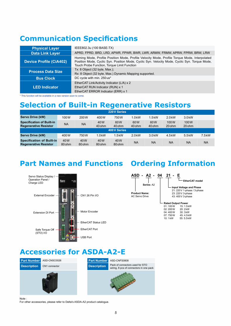
Part Names and Functions
CN1 26 Pin I/O
Communication Specifications
Accessories for ASDA-A2-EASD-CNSC0026Part NumberCN1 connectorDescription
Servo Status Display / Operation Panel / Charge LED
External Encoder
Extension DI Port
Safe Torque Off (STO) I/O
EtherCAT Status LED
Motor Encoder
EtherCAT Port
USB Port
Ordering Information
ASD - A2 - 04 21 - E
Product Name: AC Servo Drive
EtherCAT model
Input Voltage and Phase21: 220 V 1-phase / 3-phase23: 220 V 3-phase43: 400 V 3-phase
Rated Output Power 01: 100 W 15: 1.5 kW 02: 200 W 20: 2 kW04: 400 W 30: 3 kW07: 750 W 45: 4.5 kW10: 1 kW 55: 5.5 kW
Series: A2
Part Number
Description
ASD-CNFS0808
Pack of connectors used for STO wiring, 8 pcs of connectors in one pack
Note :For other accessories, please refer to Delta's ASDA-A2 product catalogue.
Physical Layer IEEE802.3u (100 BASE-TX)
Data Link Layer APRD, FPRD, BRD, LRD, APWR, FPWR, BWR, LWR, ARMW, FRMW, APRW, FPRW, BRW, LRW
Device Profile (CiA402)Homing Mode, Profile Position Mode, Profile Velocity Mode, Profile Torque Mode, Interpolated Position Mode, Cyclic Syn. Position Mode, Cyclic Syn. Velocity Mode, Cyclic Syn. Torque Mode, Touch Probe Function, Torque Limit Function
Process Data Size Tx: 8 Object (32 byte, Max.); Rx: 8 Object (32 byte, Max.) Dynamic Mapping supported.
Bus Clock DC cycle with min. 250 us*
LED IndicatorEtherCAT Link/Activity Indicator (L/A) x 2EtherCAT RUN Indicator (RUN) x 1EtherCAT ERROR Indicator (ERR) x 1
* This function will be available in a new version soon to come.
220 V SeriesServo Drive (kW) 100 W 200 W 400 W 750 W 1.0 kW 1.5 kW 2.0 kW 3.0 kWSpecification of Built-in Regenerative Resistor NA NA 40 W
40 ohm60 W
40 ohm60 W
40 ohm60 W
40 ohm100 W 20 ohm
100 W 20 ohm
400 V SeriesServo Drive (kW) 400 W 750 W 1.0 kW 1.5 kW 2.0 kW 3.0 kW 4.5 kW 5.5 kW 7.5 kWSpecification of Built-in Regenerative Resistor
40 W 80 ohm
40 W 80 ohm
40 W 80 ohm
40 W 80 ohm NA NA NA NA NA
Selection of Built-in Regenerative Resistors

6
u 220 V SeriesDimensions
100 W / 200 W / 400 W
WeightWeight
1.5(3.3)
70(2.76) 170(6.69)45(1.77)
Ø5.2(0.20)
5.5(
0.22
)16
3(6.
42)
173(
6.81
)
27.5(1.08)12(0.47)
70(2.76) 180(7.09)65(2.56)
Ø5.5(0.217)
5.4(
0.21
)16
3(6.
42)
173(
6.81
)
47(1.85)12.5(0.49)
750 W / 1 kW / 1.5 kW
2.0(4.4)
2 kW / 3 kW
2.89(6.36)
400 W / 750 W / 1 kW / 1.5 kW
2.0(4.4)
82.0(3.23)70(2.76) 203.0(7.99)
Ø5.5(0.
22)
5.4(
0.21
)20
3.0(
7.99
)
215.
5(8.
48)
62.0(2.44)14.5(0.57)
u 400 V Series
SCREW: M4×0.7MOUNTING SCREW TORQUE:14(kgf-cm)
180 (7.08)65 (2.55) 70 (2.75)
163 (6.41)
12.5 (0.49)
47 (1.85)
173 (6.81)
2 kW / 3 kW / 4.5 kW / 5.5 kW
4.6(10.1)
123.5 (4.86)
107 (4.21)70.2
(2.76) 205.5 (8.09)
230 (9.05)
8 (0.31)
245 (9.64)
107 (4.21)
7 (0.27)
SCREW: M4×0.7MOUNTING SCREW TORQUE:14(kgf-cm)
Footnote:1. Dimensions are in millimeters (inches); Weights are in kilograms (kg) and pounds (lbs)2. Dimensions and weights of the servo drive may be revised without prior notice.
7.5 kW
5.5(12.1)
PE TERMINAL
119.5 (4.70)
232 (9.13)
107 (4.21)
SCREW: M4×0.7MOUNTING SCREW TORQUE:14(kgf-cm)
254.2 (10.00)
245 (9.64)
136 (5.35)8
70.2 (2.76)
205.5 (8.09)
5 (0.19)
260 (10.23)
Weight
Weight Weight
Weight Weight

DELTA_IA-ASDA_ASDA-A2-E_C_EN_20210916*We reserve the right to change the information in this catalogue without prior notice.
Industrial Automation HeadquartersTaiwan: Delta Electronics, Inc. Taoyuan Technology CenterNo.18, Xinglong Rd., Taoyuan District, Taoyuan City 33068, TaiwanTEL: +886-3-362-6301 / FAX: +886-3-371-6301
AsiaChina: Delta Electronics (Shanghai) Co., Ltd.No.182 Minyu Rd., Pudong Shanghai, P.R.C.Post code : 201209 TEL: +86-21-6872-3988 / FAX: +86-21-6872-3996Customer Service: 400-820-9595
Japan: Delta Electronics (Japan), Inc.Industrial Automation Sales Department 2-1-14 Shibadaimon, Minato-kuTokyo, Japan 105-0012TEL: +81-3-5733-1155 / FAX: +81-3-5733-1255
Korea: Delta Electronics (Korea), Inc.1511, 219, Gasan Digital 1-Ro., Geumcheon-gu, Seoul, 08501 South KoreaTEL: +82-2-515-5305 / FAX: +82-2-515-5302
Singapore: Delta Energy Systems (Singapore) Pte Ltd.4 Kaki Bukit Avenue 1, #05-04, Singapore 417939TEL: +65-6747-5155 / FAX: +65-6744-9228
India: Delta Electronics (India) Pvt. Ltd.Plot No.43, Sector 35, HSIIDC Gurgaon, PIN 122001, Haryana, IndiaTEL: +91-124-4874900 / FAX: +91-124-4874945
Thailand: Delta Electronics (Thailand) PCL. 909 Soi 9, Moo 4, Bangpoo Industrial Estate (E.P.Z), Pattana 1 Rd., T.Phraksa, A.Muang, Samutprakarn 10280, ThailandTEL: +66-2709-2800 / FAX: +66-2709-2827
Australia: Delta Electronics (Australia) Pty Ltd.Unit 20-21/45 Normanby Rd., Notting Hill Vic 3168, AustraliaTEL: +61-3-9543-3720
AmericasUSA: Delta Electronics (Americas) Ltd.5101 Davis Drive, Research Triangle Park, NC 27709, U.S.A.TEL: +1-919-767-3813 / FAX: +1-919-767-3969
Brazil: Delta Electronics Brazil Rua Itapeva, 26 - 3°, andar Edificio Itapeva, One - Bela Vista 01332-000 - São Paulo - SP - Brazil TEL: +55-12-3932-2300 / FAX: +55-12-3932-237
Mexico: Delta Electronics International Mexico S.A. de C.V.Gustavo Baz No. 309 Edificio E PB 103Colonia La Loma, CP 54060Tlalnepantla, Estado de MéxicoTEL: +52-55-3603-9200
EMEAEMEA Headquarters: Delta Electronics (Netherlands) B.V. Sales: [email protected] Marketing: [email protected] Technical Support: [email protected] Customer Support: [email protected] Service: [email protected]: +31(0)40 800 3900
BENELUX: Delta Electronics (Netherlands) B.V.Automotive Campus 260, 5708 JZ Helmond, The Netherlands Mail: [email protected]: +31(0)40 800 3900
DACH: Delta Electronics (Netherlands) B.V.Coesterweg 45, D-59494 Soest, GermanyMail: [email protected]: +49(0)2921 987 0
France: Delta Electronics (France) S.A.ZI du bois Challand 2, 15 rue des Pyrénées, Lisses, 91090 Evry Cedex, France Mail: [email protected]: +33(0)1 69 77 82 60
Iberia: Delta Electronics Solutions (Spain) S.L.UCtra. De Villaverde a Vallecas, 265 1º Dcha Ed. Hormigueras – P.I. de Vallecas 28031 Madrid TEL: +34(0)91 223 74 20
Carrer Llacuna 166, 08018 Barcelona, SpainMail: [email protected]
Italy: Delta Electronics (Italy) S.r.l.Via Meda 2–22060 Novedrate(CO) Piazza Grazioli 18 00186 Roma ItalyMail: [email protected]: +39 039 8900365
Russia: Delta Energy System LLC Vereyskaya Plaza II, office 112 Vereyskaya str. 17 121357 Moscow Russia Mail: [email protected]: +7 495 644 3240
Turkey: Delta Greentech Elektronik San. Ltd. Sti. (Turkey) Şerifali Mah. Hendem Cad. Kule Sok. No:16-A 34775 Ümraniye – İstanbulMail: [email protected]: + 90 216 499 9910
MEA: Eltek Dubai (Eltek MEA DMCC)OFFICE 2504, 25th Floor, Saba Tower 1, Jumeirah Lakes Towers, Dubai, UAE Mail: [email protected]: +971(0)4 2690148