digitization
DESCRIPTION
DigitizationTRANSCRIPT

00.02.51 - 020
1
Process control
Electro/Digital
Resistance circuits
Electrical components can be joined together in various ways. In a series circuitthe components are placed one after the other in a chain.In a parallel circuit each individual component is connected to the same potentialdifference. A combination circuit has the characteristics of both a series and aparallel circuit.
This lessons deals with the major properties of series circuits, parallel circuitsand circuits with a combination of resistances.
Contents of the lesson
1 Resistances in series
2 Resistances in parallel
3 Resistances in a combination circuit
The copyright in this material is vested in Shell Global Solutions International B.V., The Hague, The Netherlands and Shell Netherlands Raffinaderij B.V. All rightsreserved. Neither the whole or any part of this document may be reproduced, stored in any retrieval system or transmitted in any form by any means (electronic,mechanical, reprographic, recording or otherwise) without the prior written consent of the copyright owner.
Process control / 00.02.51 – 020
2
Lesson
1. Resistances in seriesThe electric current flowing through resistances in series is the same at everypoint. In the battery, the number of electrons that are moved to the negativeterminal is equal to the number of electrons returning to the positive terminal. Inother words, the electric current through resistances in series is the samethroughout, both in the resistances and in the battery. This will be illustrated inan example.
5815-020-001-P
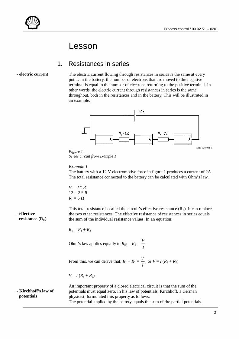
Figure 1Series circuit from example 1
Example 1The battery with a 12 V electromotive force in figure 1 produces a current of 2A.The total resistance connected to the battery can be calculated with Ohm’s law.
V = I * R12 = 2 * RR = 6 Ω
This total resistance is called the circuit’s effective resistance (RE). It can replacethe two other resistances. The effective resistance of resistances in series equalsthe sum of the individual resistance values. In an equation:
RE = R1 + R2
Ohm’s law applies equally to RE: RE = IV
From this, we can derive that: R1 + R2 = IV
, or V = I (R1 + R2)
V = I (R1 + R2)
An important property of a closed electrical circuit is that the sum of thepotentials must equal zero. In his law of potentials, Kirchhoff, a Germanphysicist, formulated this property as follows:The potential applied by the battery equals the sum of the partial potentials.
- electric current
- effective resistance (RE)
- Kirchhoff’s law of potentials

Process control / 00.02.51 – 020
3
Question 1Three resistances, R1, R2 and R3, are connected in series to a 200 V potential.The current is 2 A. R1 = 20 Ω and R2 = 10 Ω. Calculate the resistance ofR3.Resistances in parallel
2. Resistances in parallelIn a parallel circuit each individual component is connected to the same battery,thus forming separate current paths. Kirchhoff’s law of currents applies at thenodal points where these currents are created or come together.In his law of currents, Kirchhoff formulated this property of partial currents asfollows:The sum of the currents at any nodal point always equals zero.
In practice, Kirchhoff’s law of currents says that all currents flowing to anynodal point must equal the currents flowing from it.
According to Kirchhoff’s law of currents:
I = I1 + I2
This may also be written as:
ERV
= 1R
V +
2RV
For the effective resistance, this may be reduced to:
ER1
= 1
1R
+ 2
1R
A different expression for the effective resistance in a parallel circuit is:
RE = )R(R) R (R
21
21
+∗
- Kirchhoff’s law of currents

Process control / 00.02.51 – 020
4
Example 2In the parallel circuit of figure 2, is the electromotive force 60 V and the current5 A. What is the effective resistance?
V = I * RE
60 = 5 * RE
RE = 12 Ω
Alternatively, the effective resistance can be calculated with the aid of theequation given earlier.
ER1
= 1
1R
+ 2
1R
ER1
= 151
+ 601
= 604
+ 601
= 605
= 121
RE = 12 Ω
5815-020-002-P
Figure 2Parallel circuit from example 2
Question 2Three resistances are connected in parallel. Calculate the value of R3 ifR1 = 60 Ω , R2 = 20 ? and RE = 5 ?
Question 3Three resistances are connected in parallel to a 220 V potential. Calculate thevalues of It, R2, R3 and RE if R1 = 200 Ω , I2 = 0.4 A and I3 = 0.5 A
Question 4Are the front and rear lights of a bicycle connected in series or in parallel?

Process control / 00.02.51 – 020
5
3. Resistances in a combination circuitThe various combinations of series and parallel circuits will be illustrated withthe aid of a few examples. The figure below shows three resistances in acombination circuit.
5815-020-003-P
Figure 3Combination circuit from example 3
Example 3We wish to calculate the effective resistance and all partial currents in thecircuits illustrated above. To this end, we must first calculate the effectiveresistance of R2 and R3:
1
1
ER =
2
1R
+ 3
1R
1
1
ER =
41
+ 121
= 123
+ 121
= 124
RE1 = 4
12 = 3 Ω
Resistances R1 and RE1 now form a series connection. The effective resistance ofthe complete combination circuit is:
RE = R1 + RE1
RE = 5 + 3 = 8 Ω
The total current I can now be calculated.
V = I * RE
24 = I * 8
I = 824
= 3 A

Process control / 00.02.51 – 020
6
This current flows through both resistances R1 and RE1. The potential across RE1
can now be calculated as follows:VE1 = I * RE1
VE1 = renamed V2
V2 = 3 * 3 = 9 V
V1 = I * R1
V1 = 3 * 5 = 15 V
Check: V = 9 + 15 = 24 VTherefore: V = V1 + V2
The potential E2 is across both R2 and R3. Therefore:V2 = I2 * R2
9 = I2 * 4
I2 = 49
= 2.25 A
V2 = I3 * R3
9 = I3 * 12
I3 = 129
= 0.75 A
Check: I = 2.25 + 0.75 = 3 ATherefore: I = I2 + I3
Question 5A 5 Ω resistance is connected in series to two parallel resistances of 20 Ω and60 Ω respectively. The combination circuit is connected to a 120 V potential.Calculate the current flowing through each resistance and the potential acrosseach resistance.
Question 6Calculate the readings of the voltmeter and the ammeter in figure 4, assumingthe current flowing through the 7.2 Ω resistance is 10 A. The meters are idealmeters.
5815-020-004-P
Figure 4Measuring arrangement from question 6

Process control / 00.02.51 – 020
7
SummaryThe electric current flowing through resistances in series is the same throughout,both in the resistances and in the battery.
The effective resistance of resistances in series equals the sum of the individualresistance values. In a equation: RE = R1 + R2
According to Kirchhoff’s law of potentials the potential applied by the batteryequals the sum of the partial potentials.
According to Kirchhoff’s law of currents the sum of the currents at any nodalpoint always equals zero.
The effective resistance in a parallel circuit can be calculated with the followingequation:
ER
1 =
1
1R
+ 2
1R
, or: RE = )() (
21
21
RRRR
+∗

Process control / 00.02.51 – 020
8
TestExercisesDo not send in your answers for correction
1. Two resistances, R1 and R2, are connected in series to a potential V. Thecurrent flowing through R2 is 4 A. The potential across R1 is 320 V andR2 = 10 Ω . Calculate the resistance of R1, the potential across R2 and thepotential V.
2. Three resistances, R1 = 240 Ω , R2 = 100 Ω and R3 = 120 Ω , are connected inparallel. The current flowing through R1 is 250 mA. Calculate the currentsin the other resistances and the effective resistance.
3. A current of 150 A is divided over two parallel resistances, such that thecurrents in the resistances are 147 A and 3 A respectively. The value of thehigher resistance is 7.35 Ω . Calculate the value of the lower resistance.
4. All ammeters in the circuits of the figure below indicate exactly the samecurrents. Calculate the values of the two unknown resistances.
5815-020-005-P
Circuit exercise 4
5. What does the term effective resistance mean?
6. A set of decorative lights consists of a number of 14 V lamps in series. Howmany lamps are required if they are to be connected to 220 V? Whathappens if one of the lamps is unscrewed?
7. A 6 V, 0.2 A lamp is to be used for a 120 V potential. What is the value ofthe resistance that must be connected in series with the lamp?

Process control / 00.02.51 – 020
9
Answers to the questions in the lesson1. The potential across the first two resistances can be calculated as follows:
(20 * 2) + (10 * 2) = 60 V
Therefore, according to Kirchhoff’s law of potentials, the potential acrossthe third resistance must equal 200 – 60 = 140 VWith the aid of Ohm’s law, the resistance can be calculated from thepotential across R3:
2140
= 70 Ω
2. The effective resistance in a parallel circuit can be calculated with thefollowing equation:
ER1
= 1
1R
+ 2
1R
+ 3
1R
Substituting the data yields:
51
= 601
+ 201
+ 3
1R
12024
= 120
2 +
1206
+ 3
1R
Therefore, R3 must equal 16120
= 7.5 Ω
3. The partial current flowing through R1 can be calculated from the potential
across this first resistance: I1 = 200220
= 1.1 A
Therefore, according to Kirchhoff’s law of currents, the total currentthrough the circuit must equal: 1.1 + 0.4 + 0.5 = 2 AWith the aid of Ohm’s law, it is easy to calculate the effective resistance:
RE = 2
220 = 110 Ω
As far as R2 is concerned: R2 * 0.4 = 220. Therefore, R2 is 550 Ω .The same applies to R3: R3 * 0.5 = 220. Therefore, R3 is 440 Ω .
The effective resistance can be checked via an alternative route:
ER1
= 1
1R
+ 2
1R
+ 3
1R

Process control / 00.02.51 – 020
10
Substituting the data yields:
ER1
= 2001
+ 5501
+ 4401
ER1
= 220011
+ 2200
4 +
22005
Therefore, RE must equal 20
2200 = 110 Ω
4. The front and rear lights of a bicycle are in parallel because they must notgo out together when either the front or the rear light fails.
5. First, we calculate the effective resistance of the circuit’s parallel part:
ER1
= 1
1R
+ 2
1R
Substituting the data yields:
ER1
= 201
+ 601
ER1
= 603
+ 601
The effective resistance is therefore 4
60 = 15 Ω . The circuit’s total effective
resistance is 15 + 5 = 20 Ω. According to Ohm’s law, a main current of
20120
= 6 A flows through the first resistance. Consequently, the potential
across this first resistance is 5 * 6 = 30 V. According to Kirchhoff’s law ofpotentials, 120 – 30 = 90 V remains for the circuit’s parallel part.
The current flowing through the respective parallel resistances is
2090
= 4.5 A and 6090
= 1.5 A

Process control / 00.02.51 – 020
11
6. The effective resistance of the left-hand combination circuit equals4.8 + 7.2 = 12 Ω . A 10 A main current flows through this part of the circuit.According to Ohm’s law, the voltmeter must read 12 * 10 = 120 VThe effective resistance of the right-hand combination circuit equals0.83 + 4.5 = 5.33 Ω. Since the potential across this part of the circuit is also
120 V, the main current through this part must equal 5.33120
= 22.51 A
The current flowing through the ammeter must therefore equal10 + 22.51 = 32.51 A
Answers to the exercises1. The electric current flowing through resistances in series is the same at
every point. The current in R1 must therefore be 4 A. Since the potential
across R1 is 320 V, it follows that its resistance equals 4
320 = 80 Ω
Therefore, the potential across R2 is 4 * 10 = 40 V and the total potential Vis 360 V.
2. In a parallel circuit each individual component is connected to the samepotential difference. The potential across R1 is 240 * 0.25 = 60 V. Since it isequal to the potential across the other resistances, we can calculate thepartial currents flowing through the second and third resistances. The
current in R2 equals 10060
= 0.6 A whereas the current in R3 is 12060
= 0.5 A
The effective resistance of this parallel circuit is calculated by dividing thepotential by the sum of the partial currents: I = 0.25 + 0.6 + 0.5 = 1.35 A
This yields an effective resistance of 1.3560
= 44.44 Ω
3. The weakest partial current will flow through the highest resistance, i.e. 3A.The potential across the highest resistance therefore equals7.35 * 3 = 22.05 V. Consequently, the potential across the lowest resistanceis 22.05 V as well. The value of the lowest resistance therefore equals
14722.05
= 0.15 Ω
4. Since all resistances in the second circuit are known, the effective resistanceof this combination circuit can be calculated as being 300 Ω , the same as theunknown resistance in the first circuit.The value of the unknown resistance in the third circuit must be 100 Ω forthe effective resistance to be 300 Ω .

Process control / 00.02.51 – 020
12
5. A circuit’s total resistance is called its effective resistance (RE), which canreplace all the resistances in the circuit.
6. 16 lamps would result in a 224 V potential across all the lamps takentogether. If one lamp is unscrewed, all the lamps will go out. It is after all aseries circuit.
7. The series resistance must allow a 0.2 A current if a potential of120 – 6 = 114 V is applied. According to Ohm’s law, this would mean a
resistance of 0.2114
= 570 Ω