digital testing in the context of digital engineering
TRANSCRIPT
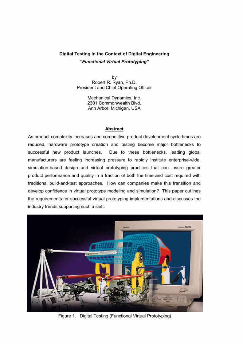
Digital Testing in the Context of Digital Engineering“Functional Virtual Prototyping”
byRobert R. Ryan, Ph.D.
President and Chief Operating Officer
Mechanical Dynamics, Inc.2301 Commonwealth Blvd.Ann Arbor, Michigan, USA
AbstractAs product complexity increases and competitive product development cycle times are
reduced, hardware prototype creation and testing become major bottlenecks to
successful new product launches. Due to these bottlenecks, leading global
manufacturers are feeling increasing pressure to rapidly institute enterprise-wide,
simulation-based design and virtual prototyping practices that can insure greater
product performance and quality in a fraction of both the time and cost required with
traditional build-and-test approaches. How can companies make this transition and
develop confidence in virtual prototype modeling and simulation? This paper outlines
the requirements for successful virtual prototyping implementations and discusses the
industry trends supporting such a shift.
Figure 1. Digital Testing (Functional Virtual Prototyping)

Introduction
The current BMW 3-series sedan came to market amidst a flurry of accolades and awards.
“Perfection down to the last detail” was an overriding philosophy throughout the design
process used to create this latest version of “the Ultimate Driving Machine.” According to
BMW Magazine [1], the development process involved five and a half years, 2.6 million man-
hours, 130 hand-made system-level hardware prototypes created at a cost of roughly
$350,000 per vehicle, and some 2,400 new components. Anti-lock braking systems,
traction-control, advanced multi-link suspension systems, state-of-the art safety systems,
and a chassis/powertrain combination that operates in perfect unison are just a few of the
complex engineering characteristics of this stellar vehicle.
Based on the rate of change in the automotive industry, it is safe to say that the remarkable
standard of excellence set by this BMW 3-series vehicle will be surpassed by many new
vehicles in a few short years to come. New vehicles will incorporate more advanced
technology so that they ride smoother, react faster, have more pleasing sound qualities, last
longer, require less maintenance, protect occupants better, and deliver more value to the
customer. Moreover, these new vehicles will be developed in roughly half of the
development time of the current 3-series. The cost of producing a system-level hardware
prototype will probably not substantially change, but the overall development cost for these
new vehicles are projected to plummet along with the development time. How can this be?
What will facilitate this remarkable advancement? The answer is Virtual Prototyping.
Simulation-based design practices allow product designers, engineers, and analysts to more
quickly assess form, fit, function, and manufacturability of new products throughout concept
design, concept refinement, detailed design, release, and production. No longer is it
necessary to wait months to build a hardware prototype, instrument it, run tests on it, and
make a small number of expensive modifications to it in order to assess proposed design
changes. Instead, participants in the design process are able to construct accurate virtual
prototypes in less than a week, exercise the models through hundreds of tests with
thousands of variations, and optimize the form, fit, function, and manufacturing
characteristics in a fraction of the cost of traditional hardware prototype processes.

The VisionMove away from:
Concept Product
Design - Build - Measure
Towards: Virtual Prototype
Time = $
Concept Product
Development time WITH virtual prototypes
Development time WITHOUT virtual prototypes
Figure 2. Virtual Prototype of a BMW Sedan
Figure 3. Moving from Physical to Virtual Prototyping

What is required to implement a successful virtual prototyping process? Why hasn’t this
been done previously? What industry trends are enabling such a transition? What are
potential pitfalls and limiting factors? What are the critical success-factors for a truly
effective virtual prototyping system? The purpose of this paper is to address precisely these
questions and to stimulate action.
Traditional CAD/CAM/CAE vs. System-level Virtual Prototyping
Traditional CAD/CAM/CAE practices throughout the 1970’s and 1980’s focused on a
concept referred to as “art-to-part.” Nearly all engineering software activity was oriented
toward the design, development, and manufacturing of higher quality parts. Detailed, three-
dimensional solid modelers (CAD) allowed for quick part design and understanding of “form.”
Finite element software (CAE) made it feasible to perform detailed meshing and analysis of
structural effects, thermal effects, and vibratory characteristics, or “function,” of individual
parts. Software aimed at improving “manufacturability” of parts (CAM) provided better
control of machine tools, robots, mold procedures, stamping procedures, forging processes,
etc.
These traditional CAD/CAM/CAE tools and processes were embraced and implemented
throughout major industries, including the automotive, aerospace, general machinery, and
electromechanical markets. For the most part, they lived up to their promise of dramatically
improving part design. In the automotive industry, for example, automotive suppliers
reported a 40% reduction in part defects over a recent five-year period. This significant
improvement was accompanied by a corresponding drop in development and manufacturing
costs attained through successful implementation of better CAD/CAM/CAE tools and
processes.
Unfortunately, during the same five-year period that automotive part suppliers were
achieving a 40% reduction in part defects, the vehicle manufacturers (OEMs) who were
using these parts to assemble and market full vehicles experienced only a 20% reduction in
warranty costs. In some sense, this was a surprise to many OEMs who expected a one-to-
one correspondence between part defects and warranty costs. In retrospect, it seems
perfectly sensible. Optimal part design rarely leads to optimal system design. For

example, when perfectly good brakes are combined with a perfectly good suspension
system and a fine chassis, the resulting combination often performs in a less-than-stellar
manner. Clearly, the interaction of form, fit, function, and assembly of all parts in a product
is a major contributor to overall product quality. We may be reaching levels of diminishing
return in applying CAD/CAM/CAE technologies to part design. The big opportunity toincrease quality and reduce time and cost has now shifted to the system level.
More significant returns on investment can be realized today through the effective use of
simulation-based design processes and virtual prototyping applied to system-leveldesign. Manufacturers now need a means to quickly assess form and fit of entire
assemblies of three-dimensional solid models comprising a product (Digital Mock-Up). They
need to be able to assess the operating function of the entire assembled product (Functional
Virtual Prototyping), not just the component parts. And they need to investigate the entire
manufacturing and assembly of the product (Virtual Factory Simulation), not just the creation
of the parts. As global product manufacturers began to realize this fact over the last 2-5
years, it was natural for them to look for extensions to their traditional CAD/CAM/CAE
systems to address system-level design. Part-focused CAD/CAM/CAE providers hurried to
extend their software to address system-level designs with varying levels of success. But
simple extensions of part design paradigms to system-level design often lead to impractical
software products. For instance, as manufacturers tried to construct large assemblies of
solid models to facilitate system-level interference detection and virtual fly-through, the
rendering performance of most traditional CAD/CAM/CAE systems became unacceptably
slow (e.g., measured in hours). Similarly, manufacturers investigating system level
Figure 4. Component- and System-Focused CAD/CAM/CAE
Product Data Management System
Traditional Component-focused CAD/CAE/CAM
System-focused Virtual Prototyping
Design - Development - Production
CAD CAE CAM
Virtual
Mock-up
Virtual
Prototyping
Virtual
Production(Digital Mock-Up ) (Functional Virtual Prototyping) (Virtual Factory Simulation)

operating performance attempted to combine all of their component finite element models
and perform nonlinear finite element system simulations. These typically took Cray-weeks of
simulation time to predict only seconds of real operating performance, thus making design
trade-off investigations impractical. Similar problems occurred in manufacturing and
assembly.
New methodologies, specifically oriented toward rapid system-level design, had to be
adopted. The growth in simulation-based design tools has now shifted away from traditional
CAD/CAM/CAE software and toward these newer system-focused solutions. Specifically,
these system-level solutions include Digital Mock-Up tools to investigate product form and fit,
Functional Virtual Prototyping tools to assess product function and operating performance,
and Virtual Factory Simulation to assess manufacturability and assembly of the product.
Enterprise-wide, Product Data Management (PDM) is the “glue” that enables these system-
focused solutions to be successful by making all of the up-to-date component data readily
available and manageable.
Digital Mock-Up (DMU) solutions that make efficient use of tessellated three-dimensional
component solid models were pioneered by Tecoplan, Engineering Animation, Clarus, and
Division among others. These allow efficient design collaboration, mark-up, fly-through, and
interference/collision detection. Integrated with Product Data Management Systems, these
Digital Mock-Up products provide an excellent means to insure that all of the parts of the
product will fit together properly and that the product will appear as specified.
Functional Virtual Prototyping solutions make efficient use of three-dimensional component
solid models and modal representations of component finite element models to accurately
predict the operating performance of the product in virtual lab tests and virtual field tests.
Mechanical Dynamics pioneered this field with its ADAMS system simulation product line
and is expanding its coverage through its partnership with MTS systems, nCode, and the
solid modeling and finite element solution vendors.
Virtual Factory Simulation was pioneered by Tecnomatix and Deneb. With these solutions,
the entire manufacturing and assembly of products can be simulated, and field maintenance
of products can be assessed as well.

The combination of Digital Mock-up, Functional Virtual Prototyping, and Virtual Factory
Simulation provide a means for realizing an effective transition from hardware prototyping
practices to software prototyping practices with all of the concomitant benefits. The
remainder of this paper will focus on the subject of Functional Virtual Prototyping and how it
can be implemented.
Functional Virtual Prototyping
Effective Functional Virtual Prototyping (FVP) allows the full operation of the product to be
considered and evaluated early enough in the design process to allow for ‘function” to truly
drive “form” and “fit.” It also allows multi-function optimization to be realized, such that a true
balance can be obtained between competing functional requirements involving performance,
safety, durability, cost, comfort, etc. These two benefits were largely impractical in traditional
development cycles involving extensive reliance on hardware prototypes. In addition to
these benefits, functional virtual prototyping has proven effective in facilitating tighter and
more successful relationships between manufacturers and their lead suppliers.
System-focused Virtual Prototyping
VirtualMock-up
Virtual Prototyping &Design Refinement
VirtualProduction
SystemAssembly
FlyThrough
MotionEnvelopes
Collisions
...
Motion/Handling
Vibration/Noise
Durability/Fatigue
Safety/Impact
Ergonomics/Comfort
...
Tolerance
Robotics
Assembly
Sequencing
...
Figure 5. Technology Segments of System-Focused CAD/CAM/CAE
(Digital Mock-Up) (Functional Virtual Prototyping) (Virtual Factory Simulation)

Deployment of Functional Virtual Prototyping typically involves five phases:
Build, Test, Validate, Refine, and Automate.
THE PHASES OF VIRTUAL PROTOTYPING
Design Problem
Cut Timeand Cost
IncreaseQuality
IncreaseEfficiency
Improved Product
Build… a model of your design usingComponent Solid ModelsComponent FE ModelsSystem Constraints & Forces
Test… your design usingSystem Virtual PrototypesVirtual Test MachinesVirtual Test Tracks
Validate… your model byCorrelation with Physical Tests forRide & Handling, NVH, Durability(Parameter Sensitivity Analyses)
Refine… your model and design byFlexible Parts Forcing FunctionsHydraulics Control Systems Design-of-Experiments
Automate… your design process usingTemplate-based DesignIntegration with DMU,CAD, CAE,and PDM
Do the resultsmatch?
No
Yes
Figure 6. Functional Virtual Prototyping Process
Figure 7. Illustrated Phases of Functional Virtual Prototyping
Product Data Management System
System-focused Virtual Prototyping
Build Test Validate Refine Automate

Build
During the Build phase, virtual prototypes are created of both the new product concept and
any target products which may already exist in the market. In the early concept stage, the
virtual prototype models of the new product concept are kept simple and are most often
driven by desired functionality data curves, rather than by specific product topologies.
Appropriate target setting is, of course, very important. The desired functionality data curves
should be derived from a customer Quality Function Deployment (QFD) study that identifies
the desired operating performance. For instance, in the initial design of a vehicle
suspension system, the virtual prototype model often involves only the overall vehicle body
and a set of vehicle suspension curves that relate the movement of the body to the
movement of the wheels. These data curves embody the desired suspension
characteristics. During later model refinement, specific suspension topologies are chosen
(e.g., McPherson Strut) and the software optimizes suspension geometry and structural
properties to yield the relationship described by the chosen curves. Similarly, to create
models of target products, the actual target product is physically tested and its
characteristics are accurately measured. This data is incorporated into a system-level model
of the competitive vehicle to use later during the evaluation phases.
Comparison Vehicle
Target VehicleVirtual Prototype
Sub-SystemVirtual Prototype
Sub-SystemTargets
Component TargetsComponent Virtual Prototype
Target Setting
Vehicle Targets
QFD
Figure 8. Target Setting via QFD and Comparison Vehicle

A modular system design process facilitates functional virtual prototyping and the
manufacturer-supplier interaction. Clear inputs and outputs between various subsystems
permit the development of multiple subsystem models with varying levels of model fidelity
and complexity. These subsystem and system-level virtual prototypes are comprised of rigid
and flexible representations of component parts connected through mathematically defined
constraints. The geometry and mass properties for the parts are derived from component
solid models; while the structural, thermal, and vibratory properties are derived from
component finite element models or experimental tests. The most effective implementations
of virtual prototyping begin in this Build phase with a close cooperation between engineering
analysts and test engineers. Also, up-front planning of what product parameters may be
varied in the design cycle, and how manufacturers and suppliers are going to share models,
can be tremendously helpful.
Vehicle Manufacturer
Voiceof the
Customer
System-LevelSpecs
HardwarePrototyping& Testing
Suppliers
ComponentSpec.
Sub-SystemCAE
Sub-SystemSpec.
System-LevelVirtual
Prototyping
Multi-Function Optimization
Powertrain Body Interior Electrical Chassis
Figure 9. Modular System Design Facilitates OEM-Supplier Relationship
Figure 10. Virtual Prototyping Allows Multi-Function Optimization

Test
Perhaps the single most important axiom for successful functional virtual prototyping is to
simulate as you test. Testing of hardware prototypes has traditionally involved both lab
tests and field tests in various configurations. With virtual prototyping, we need to create
virtual equivalents of the lab tests and the field tests. By doing this, we greatly facilitate
model validation through testing, and we break down the cultural barriers to the adoption of
virtual prototyping practices. With regard to lab tests, successful virtual prototyping dictates
that we need to construct virtual test rigs that reproduce the test procedures and boundary
conditions of the real fixture and machine. With field tests, we need to construct models that
represent the actual operating conditions of the product in the field. This may involve virtual
test tracks in automotive, virtual landing strips in aircraft simulation, etc.
Effective implementations of Functional Virtual Prototyping require a tight synergy between
physical testing of hardware prototypes (components and systems) as well as simulation-
based testing of virtual prototypes (components and systems). Testing requirements vary
Figure 11. Field & Lab Testing: Virtual and Physical

during the different stages of the design process. At the outset of a new product design
based on virtual prototyping, hardware testing is instrumental in two ways. First, component
tests are performed using various real component alternatives. These tests provide good
characteristic data for a complete system-level virtual prototype model. Secondly, full
system hardware tests are conducted using target products. This allows for the
simultaneous development of virtual prototypes of competing products so that performance
comparisons can be made throughout the design and development cycle.
Then, during concept design, virtual testing is used to exercise the new system model
through a limited number of actual test scenarios such that performance data can be
collected and validation can be performed. For companies that are initiating new virtual
prototyping processes, it is imperative that they build a first system-level physical prototype
at this stage in order to insure confidence in the simulation model. Companies who have
been through this process a number of times have learned how to validate the modeling
assumptions such that a physical prototype is unnecessary at this stage.
Once initial validation has been achieved by correlating the test results of the physical and
virtual system prototypes, the true value of virtual prototyping begins to become apparent.
Thousands of system variations, component choices, parameter choices, and tolerances can
be examined through simulation and the results can be used to confidently make design
choices about the new product. This will be discussed later in the section entitled “Refine.”
Figure 12. Typical Parameter Study With Virtual Prototype

Testing remains an important part of functional virtual prototyping throughout the design
cycle. Virtual testing is conducted continuously. Physical testing is introduced at various
stages to either re-validate the model after significant refinement or to test certain
configurations of the product containing design parameters outside of those for which the
model has been validated.
Validate
The importance of accurate validation of system-level models and modeling assumptions
should not be under-emphasized. Functional Virtual Prototyping can yield a wealth of
information to support rapid decision-making. It is critical to insure that this information
reflects the actual operating performance of the new product. The validation phase is not
overly difficult, but often is not approached with as much rigor as is warranted. The
companies with the very best records in making effective use of functional virtual prototyping
have invested significant time and resources in building a validation library. This library
defines how models need to be constructed so that simulation performance results can be
easily compared with test results. The library catalogues past validation work and
summarizes modeling assumptions that have been validated. And the library is integrated
with an internal product data management system so that data and information is readily
available.
Good simulation tools and processes can greatly facilitate the validation process. For
instance, a simulation software product that provides quick information on design sensitivity
to various parameter changes can pinpoint areas of a model to be investigated to improve
correlation between experiment and simulation. Also, as stated earlier, it is important to
“simulate as you test,” meaning that the same testing and instrumentation procedures should
be used both in the physical and virtual test process.
In a typical validation process, the physical and virtual models are tested identically and
baseline results are derived. The results are compared either manually or in automated
computer-based fashion. Discrepancies are noted in specific performance results. Design
sensitivity analyses are performed on the virtual model to identify design parameters or
model areas that significantly contribute to the performance results that do not correlate.
Then, a mixture of manual changes and computerized nonlinear optimization techniques are

employed to make changes to the model parameters identified or the test procedures until
acceptable correlation is achieved and the model is validated across the different tests.
In a recent validation process, a virtual prototype of a Formula 1 race car was tested on a
virtual representation of the Imola race course in Italy. A virtual driver model learned the
course and was used to duplicate the behavior of a real race driver. Lap times were
compared between the virtual car and a real car driven by a professional driver. The virtual
prototype delivered a lap time that was within 0.1 seconds of the real driver. More
importantly, a comparison of the vehicle lateral acceleration levels for the real and virtual
vehicles showed outstanding correlation.
With experience, modeling assumptions can be correlated and catalogued. This allows for
the automated creation of new product virtual prototypes that can be utilized with confidence
without the need for the construction and testing of an initial physical prototype. Physical
prototypes are still needed downstream in the process to verify the design prior to
production.
Proven Technology:Accurate Prediction of Performance
Figure 13. Outstanding Correlation Using Virtual Vehicle, Driver, Roadway

Refine
Refining a virtual prototype involves two aspects, refining the fidelity and breadth of the
model, and refining the product design itself. Each of these will be discussed separately
here.
As the design process progresses, the virtual prototype models will be relied upon to
investigate more and more functionality. Initially, it may be enough to understand speed of
operation, the space envelope of operation, the total power requirements, etc. This
understanding can help drive component topology selection and overall design parameters.
Then, as issues of comfort, noise, vibration, and durability need to be addressed; the virtual
prototype model will need to be enhanced. It is important that the virtual prototype can
access subsystem models of varying complexity and model fidelity. For investigations of
more complex phenomenon, it will be important to enhance the model by replacing more and
more of the rigid subsystem models with flexible counterparts. Models of the fluid power
systems that interact with the mechanical and electrical components will need to be
represented. Automatic control systems that alter the operating performance of the product
will need to be accurately represented. These are all natural extensions of the initial virtual
prototype. Component and subassembly models of varying complexity must be constructed
in such a manner so as to be quickly interchangeable. For instance, when investigating
engine performance in a vehicle, it may be important to exercise a fairly detailed engine
model that includes a flexible valvetrain with cam-rocker contact. However, if vehicle
Figure 14. Successive Refinement of Virtual Prototype
FlexibilityControls Hydraulics
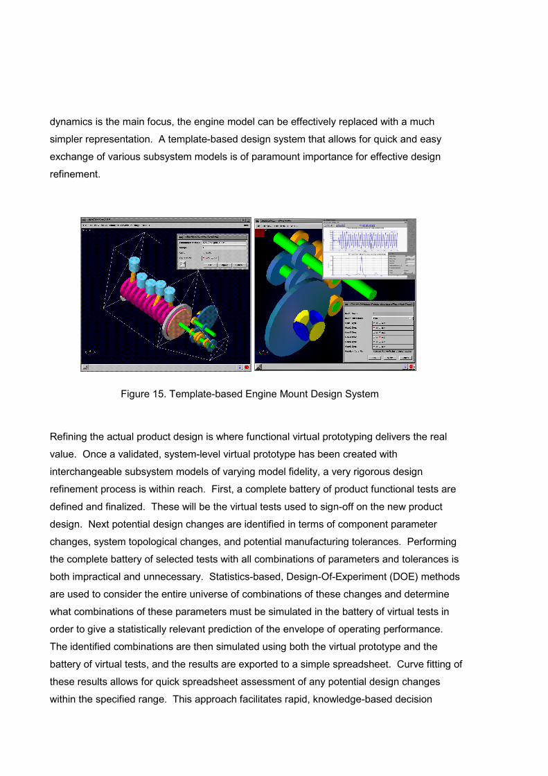
dynamics is the main focus, the engine model can be effectively replaced with a much
simpler representation. A template-based design system that allows for quick and easy
exchange of various subsystem models is of paramount importance for effective design
refinement.
Refining the actual product design is where functional virtual prototyping delivers the real
value. Once a validated, system-level virtual prototype has been created with
interchangeable subsystem models of varying model fidelity, a very rigorous design
refinement process is within reach. First, a complete battery of product functional tests are
defined and finalized. These will be the virtual tests used to sign-off on the new product
design. Next potential design changes are identified in terms of component parameter
changes, system topological changes, and potential manufacturing tolerances. Performing
the complete battery of selected tests with all combinations of parameters and tolerances is
both impractical and unnecessary. Statistics-based, Design-Of-Experiment (DOE) methods
are used to consider the entire universe of combinations of these changes and determine
what combinations of these parameters must be simulated in the battery of virtual tests in
order to give a statistically relevant prediction of the envelope of operating performance.
The identified combinations are then simulated using both the virtual prototype and the
battery of virtual tests, and the results are exported to a simple spreadsheet. Curve fitting of
these results allows for quick spreadsheet assessment of any potential design changes
within the specified range. This approach facilitates rapid, knowledge-based decision
Figure 15. Template-based Engine Mount Design System
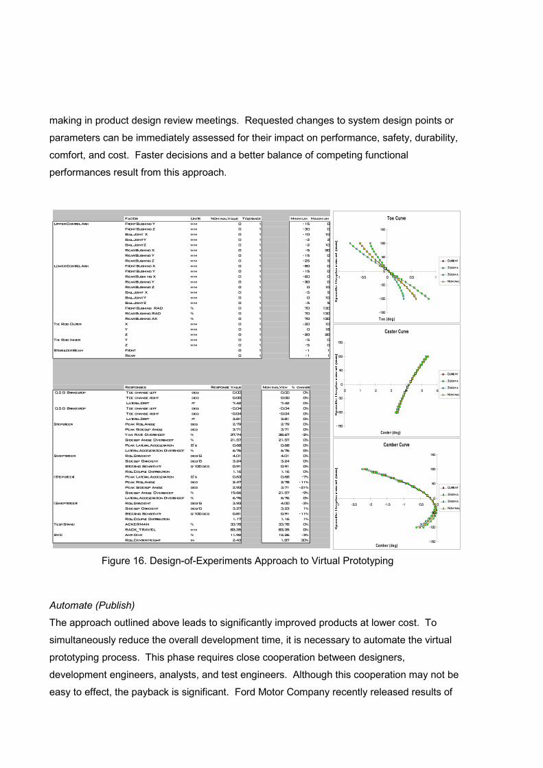
making in product design review meetings. Requested changes to system design points or
parameters can be immediately assessed for their impact on performance, safety, durability,
comfort, and cost. Faster decisions and a better balance of competing functional
performances result from this approach.
Automate (Publish)
The approach outlined above leads to significantly improved products at lower cost. To
simultaneously reduce the overall development time, it is necessary to automate the virtual
prototyping process. This phase requires close cooperation between designers,
development engineers, analysts, and test engineers. Although this cooperation may not be
easy to effect, the payback is significant. Ford Motor Company recently released results of
Toe Curve
-150
-100
-50
0
50
100
150
-1 -0.5 0 0.5 1
T oe (deg)
Current
3 sigma
3 sigma
Nominal
Caster Curve
-150
-100
-50
0
50
100
150
0 1 2 3 4 5 6
Caste r (deg)
Current
3 sigma
3 sigma
Nominal
Camber Curve
-150
-100
-50
0
50
100
150
-3 -2.5 -2 -1.5 -1 -0.5 0
Camber (deg)
Current
3 sigma
3 sigma
Nominal
SDV - Front Suspension - 10/5/94
Factor Units Nominal Value Tolerance Minimum MaximumUpper Control Arm Front Bushing Y mm 0 1 -15 0
Front Bushing Z mm 0 1 -30 0Ball Joint X mm 0 1 -10 10Ball Joint Y mm 0 1 -2 2Ball Joint Z mm 0 1 -2 10Rear Bushing X mm 0 1 -5 30Rear Bushing Y mm 0 1 -15 0Rear Bushing Z mm 0 1 -25 5
Lower Control Arm Front Bushing X mm 0 1 -80 0Front Bushing Y mm 0 1 -15 0Rear Bushi ng X mm 0 1 -60 0Rear Bushing Y mm 0 1 -30 0Rear Bushing Z mm 0 1 0 10Ball Joint X mm 0 1 -5 5Ball Joint Y mm 0 1 0 10Ball Joint Z mm 0 1 -5 5Front Bushing RAD % 0 1 70 130Rear Bushing RAD % 0 1 70 130Rear Bushing AX % 0 1 70 130
Tie Rod Outer X mm 0 1 -20 10Y mm 0 1 0 18Z mm 0 1 -20 20
Tie Rod Inner Y mm 0 1 -5 0Z mm 0 1 -5 0
Stabilizer Beam Front 0 1 -1 1Rear 0 1 -1 1
Responses Response Value Nominal Veh % change 0.2 G Brakestop Toe change left deg 0.00 0.00 0%
Toe change right deg 0.00 0.00 0% Lateral Drift ft 7.42 7.42 0%
0.5 G Brakestop Toe change left deg -0.04 -0.04 0% Toe change right deg -0.04 -0.04 0% Lateral Drift ft 3.81 3.81 0%
Stepsteer Peak Roll Angle deg 2.79 2.79 0%Peak Sideslip Angle deg 3.71 3.71 0%Yaw Rate Overshoot % 37.74 38.67 -2%Sideslip Angle Overshoot % 21.57 21.57 0%Peak Lateral Acceleration G's 0.68 0.68 0%Lateral Acceleration Overshoot % 6.76 6.76 0%
Sweptsteer Roll Gradient deg/G 4.01 4.01 0%Sideslip Gradient deg/G 3.24 3.24 0%Steering Sensitivity g/100 deg 0.91 0.91 0%Roll Couple Distribution 1.16 1.16 0%
(Stepsteer) Peak Lateral Acceleration G's 0.63 0.68 -7%Peak Roll Angle deg 2.47 2.78 -11%Peak Sideslip Angle deg 2.93 3.71 -21%Sideslip Angle Overshoot % 19.66 21.57 -9%Lateral Acceleration Overshoot % 6.76 6.76 0%
(Sweptsteer) Roll Gradient deg/G 3.93 4.00 -2%Sideslip Gradient deg/G 3.27 3.23 1%Steering Sensitivity g/100 deg 0.81 0.91 -11%Roll Couple Distribution 1.17 1.16 1%
Test Stand ACKERMAN % 33.78 33.78 0%RACK_TRAVEL mm 83.35 83.35 0%
SVC Anti-Dive % 11.92 12.26 -3%Roll Center Height in 2.43 1.87 30%
Figure 16. Design-of-Experiments Approach to Virtual Prototyping
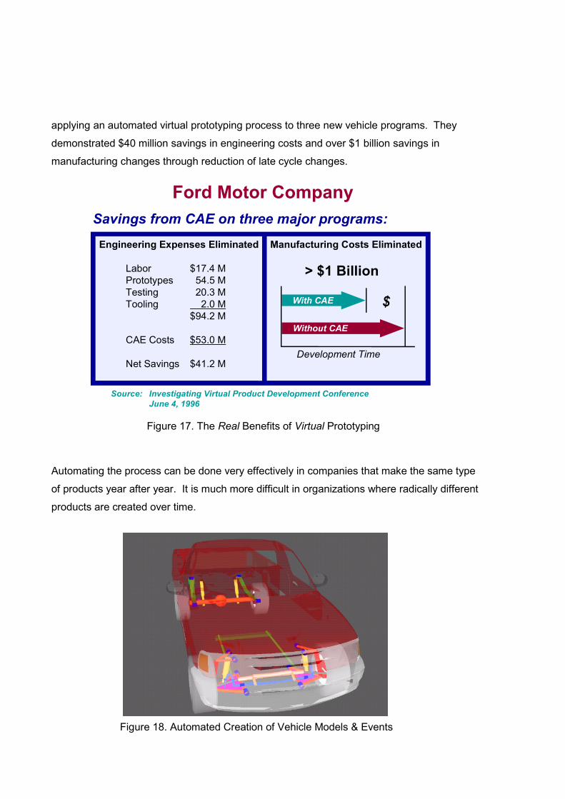
applying an automated virtual prototyping process to three new vehicle programs. They
demonstrated $40 million savings in engineering costs and over $1 billion savings in
manufacturing changes through reduction of late cycle changes.
Automating the process can be done very effectively in companies that make the same type
of products year after year. It is much more difficult in organizations where radically different
products are created over time.
Manufacturing Costs Eliminated
> $1 Billion
Development Time
Engineering Expenses Eliminated
Labor $17.4 MPrototypes 54.5 MTesting 20.3 MTooling 2.0 M
$94.2 M CAE Costs $53.0 M
Net Savings $41.2 M
Ford Motor CompanySavings from CAE on three major programs:
Source: Investigating Virtual Product Development Conference June 4, 1996
With CAE
Without CAE
$
Figure 17. The Real Benefits of Virtual Prototyping
Figure 18. Automated Creation of Vehicle Models & Events

Once the engineering analysts have worked through a few virtual prototyping cycles and
helped create validated models that can be exercised through the parameter changes
requested by the development engineers, the virtual prototyping environment can be
automated through the use of a template-based design system. It works as follows. The
engineering analysts catalogue: (1) parametric topologies that are normally considered for
new products, (2) typical parameters that are varied in the design process, (3) the range of
validity of various modeling assumptions, and (4) the different levels of subassembly model
representations required for various levels of fidelity.
Then an analyst utilizes a template-based design system to create a series of design
templates that can be used by the designers and development engineers to evaluate design
changes. These templates automate the creation of the subassembly and system models.
They allow input only within the range of the validated modeling assumptions. They hide the
complexity of the model by only presenting the parameter changes that have traditionally
been varied. And they automate the selection of subassembly representations in
accordance with the type of test or performance output that is requested. If this is integrated
with a product data management system, it allows for quick comparisons of new design
MONROE DAMPER PIRELLI TIRE
FREUDENBERG MOUNT PAULSTRA BUSHING
Figure 19. Template-based Subsystem Modeling
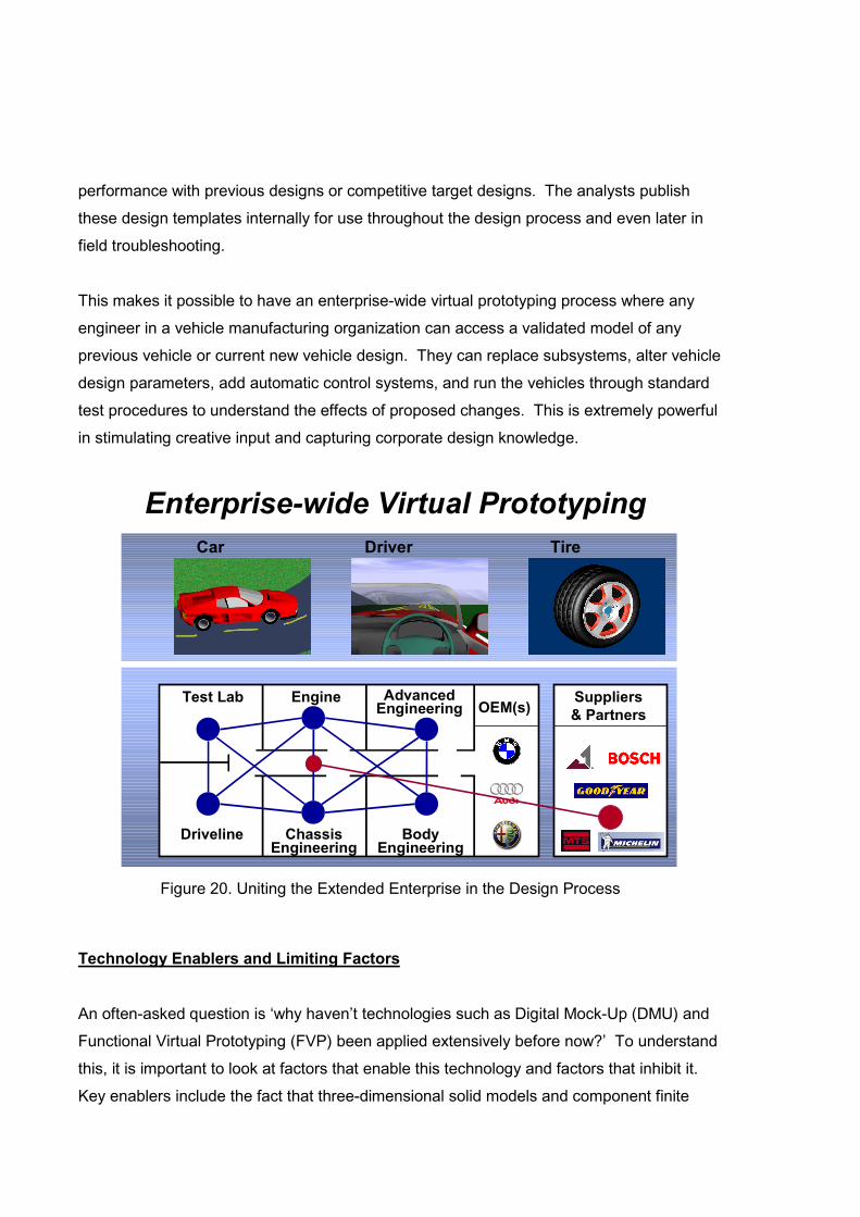
performance with previous designs or competitive target designs. The analysts publish
these design templates internally for use throughout the design process and even later in
field troubleshooting.
This makes it possible to have an enterprise-wide virtual prototyping process where any
engineer in a vehicle manufacturing organization can access a validated model of any
previous vehicle or current new vehicle design. They can replace subsystems, alter vehicle
design parameters, add automatic control systems, and run the vehicles through standard
test procedures to understand the effects of proposed changes. This is extremely powerful
in stimulating creative input and capturing corporate design knowledge.
Technology Enablers and Limiting Factors
An often-asked question is ‘why haven’t technologies such as Digital Mock-Up (DMU) and
Functional Virtual Prototyping (FVP) been applied extensively before now?’ To understand
this, it is important to look at factors that enable this technology and factors that inhibit it.
Key enablers include the fact that three-dimensional solid models and component finite
Enterprise-wide Virtual PrototypingDriverCar Tire
Test Lab Engine AdvancedEngineering
ChassisEngineering
BodyEngineering
Driveline
Suppliers& PartnersOEM(s)
Figure 20. Uniting the Extended Enterprise in the Design Process

element models are now available for most system components, unlike in the past.
Secondly, new technologies have been developed for simplifying the representation of
component data so that it can be efficiently processed in large system simulations. Thirdly,
fast graphic workstations that can quickly analyze and display system-level models have
now become inexpensive and plentiful. Also, Product Data Management systems facilitate
system-level design by making vast quantities of data available and current. These four
factors make it possible to effectively deploy DMU and FVP today.
A few limiting factors still exist which retard progress in applying these newer technologies.
First, very few universities have instituted effective training in these technologies, thus
limiting the number of knowledgeable candidates for deployment. Secondly, hardware
testing is ingrained in most manufacturing organizations and this newer technology is
sometimes viewed as a threat rather than being synergistic. And lastly, effective deployment
requires some process change within these large organizations and that requires a
significant amount of training and the passage of time for overall adoption.
Success StoryA number of major automotive OEMs and tier 1 suppliers have already made substantial
progress in using virtual prototyping to reap cost, time, and quality benefits. One of these is
Volkswagen (VW). Starting with a clear set of design performance targets, Volkswagen set
out to remake the venerable Beetle into a modern day success, not only in its styling, but
also its driveability. To achieve its goal, VW relied heavily on the use of a robust virtual
prototyping process throughout their chassis and powertrain development groups. They
made extensive use of ADAMS system simulation software to evaluate thousands of design
variations for vehicle ride and handling, vehicle durability, safety systems, as well as engine,
clutch, and transmission performance.
Figure 21. Virtual Prototype Refinements of the New Volkswagen Beetle

The results were outstanding. After thorough design in the virtual world, the vehicle behaved
splendidly in the real world! It was released to wide acclaim in both North America and
Europe. Below are just a few of the awards bestowed on this vehicle:
• 1999 North American Car of the Year Detroit Auto Show
• 1999 Automobile of the Year Automobile Magazine
• 1999 Import Car of the Year Motor Trend
• 1998 Most Appealing Car J. D. Power and Associates
• 1998 Grand Prix Award European Car Magazine
• The Best of 1998 Time Magazine
David E. Davis Jr., a writer for Automobile Magazine [2], wrote: “The New Beetle is a
landmark car.” “The car is a blast to drive.” “Steering, braking, shifting, and clutch operation
are, quite simply, a joy.” “[It] is a very safe car…” “More important, for us, is first-rate
dynamic performance.” “The New Beetle is definitely a driver’s car.” This is a rather stark
contrast to the original Beetle that was very popular, but was never known for its
performance. These great improvements were made possible in a cost-effective manner
through the heavy reliance on virtual prototyping.
Conclusion
A current bottleneck in globally competitive product design is the creation, instrumentation,
testing, and modification of system-level hardware prototypes. Traditional CAD/CAM/CAE
Figure 22. The New Volkswagen Beetle – 1999 Automobile of the Year

methodologies do not provide a good means to break this bottleneck. New products in the
Digital Mock-Up (DMU) area, Functional Virtual Prototyping (FVP) area, and Virtual Factory
Simulation (VFS) provide system-level counterparts to traditional component-focused
CAD/CAM/CAE solutions and allow for breakthroughs in speed, cost, and quality for new
product design. Key enablers are present in the market to make these technologies
practical today.
This paper provides a brief overview of Functional Virtual Prototyping and how it can be
successfully implemented in major manufacturing industries. Clearly the need for this
technology exists. Rapidly increasing product complexity coupled with declining
development budgets and time-to-market pressures mandate an alternative to singular
reliance on hardware prototype testing. New computer hardware and software have enabled
cost-effective implementations of this FVP technology. What remains is for manufacturers to
adopt enterprise-wide processes that fully incorporate virtual prototyping as a mainstream
practice and institutionalize the use of virtual prototyping software to improve design and
development of new products.
Critical success factors for FVP implementation include:
• A well-defined process
• System-level focus
• Effective target setting
• Rapid simulation turnaround
• High quality CAE infrastructure
Implementation of Functional Virtual Prototyping on an enterprise level requires a significant
commitment of time and financial resources. The benefits of making this commitment are
enormous in terms of return-on-investment and global competitiveness.
References[1] Bidrawn, Les and Kohnle, Thomas, "The New 3," BMW Magazine, Vol. 2, 1998, pp. 8-14.
[2] Davis, David, “Volkswagen New Beetle,” Automobile Magazine, Vol. 13, 1999, pp. 92-95.