digital spare parts hub of an rc helicopter 32 starter gear of a string trimmer 33 intelligent spare...
TRANSCRIPT

Digital Spare Parts
Mika Salmi, Jouni Partanen, Jukka Tuomi, Sergei Chekurov, Roy Björkstrand, Eero Huotilainen, Kirsi Kukko, Niklas Kretzschmar, Jan Akmal, Kalle Jalava, Satu Koivisto, Matti Vartiainen
Aalto University
Sini Metsä-Kortelainen, Pasi Puukko, Ari Jussila, Tuomas Riipinen, Joni Reijonen, Hannu Tanner, Markku Mikkola
VTT Technical Research Centre of Finland Ltd

Digital spare parts
Title Digital spare parts
This report is a co-publication of Aalto University and VTT Technical Research Centre of Finland Ltd
Authors Mika Salmi, Jouni Partanen, Jukka Tuomi, Sergei Chekurov, Roy Björkstrand, Eero Huotilainen, Kirsi Kukko, Niklas Kretzschmar, Jan Akmal, Kalle Jalava, Satu Koivisto, Matti Vartiainen Aalto University Sini Metsä-Kortelainen, Pasi Puukko, Ari Jussila, Tuomas Riipinen, Joni Reijonen, Hannu Tanner, Markku Mikkola VTT Technical Research Centre of Finland Ltd
ISBN ISBN 978-952-60-3746-2 http://urn.fi/URN:ISBN:978-952-60-3746-2
Date March 2018
Language English, the report is a translation of the original Finnish version
Pages 65 p.
Name of the project Digital spare parts
Funding Tekes – the Finnish Funding Agency for Innovation, Aalto University, VTT Technical Research Centre of Finland Ltd and companies participated in the project
Contact details
Mika Salmi Aalto University P.O.Box 14300, 00076 Aalto, Finland +358 50 512 2746 [email protected]
Sini Metsä-Kortelainen VTT Technical Research Centre of Finland Ltd P.O.Box 1000, 02044 VTT, Finland +358 40 525 7815 [email protected]

Digital spare parts
1/65
Preface This report is a compilation of the results of the Digital Spare Parts research project, managed and implemented by Aalto University and VTT Technical Research Centre of Finland. The main goal of the project was to create a business concept for digital spare parts and to lay down the foundations for a functional network, analyse the current and future performance and competitiveness of spare parts manufactured using a 3D printing process, increase the efficiency and speed of spare parts production and distribution with the new operating model, and create a roadmap for digital spare parts.
During the research, information was collected on the current situation of the companies and their future prospects with the help of various workshops, interviews, international research scientist exchanges, surveys and demonstration parts. Within the project, two different workshops and a final seminar were arranged, with a total of 175 participants from several tens of participating companies. More than ten Finnish companies were also interviewed from different viewpoints, and their spare parts-related business operations were examined. There were project researchers on international exchange at the Politecnico di Milano in Italy, the Munich University of Technology in Germany, and EIT Digital's Munich office in Germany. An international survey was prepared and implemented during the project. The companies were asked about the current status, future and challenges of their digital spare parts business, as well as a questionnaire on the development prospects of 3D printing that was targeted at researchers in the field. Combining the results from these surveys allowed making an assessment of the current situation of digital spare parts, how and at what speed progress is happening, and what are the key development targets of the future. Demonstration pieces were used to illustrate the manufacturing process of spare parts created using 3D printing to investigate the current performance and competitiveness of the technologies, and to compare the results with traditionally manufactured parts.
The project began on 1 January 2016 and concluded on 31 December 2017. In addition to Aalto University and VTT, the project was funded and steered by Tekes – the Finnish Funding Agency for Innovation, 3D Online Factory Oy, 3DTech Oy, ABB Oy Drives, AM Finland Oy, Hetitec Oy, Kone Oyj, Laserle Oy, Materflow Oy, Grano 3D Oy, Patria Aviation Oy, Raute Oyj, Rolls-Royce Oy Ab, Sacotec Components Oy and Wärtsilä Finland Oy. The Federation of Finnish Technology Industries was a partner in the project.
Representatives from companies involved in the project and, in particular, the members of the steering group and people participating in the various events provided valuable information and shared their views on the current situation and future prospects of digital spare parts. Without this significant input from the companies, the project execution would have remained at a fairly general level, and we could not have gone into sufficient depth regarding the intricacies of the world of spare parts thoroughly enough. Indeed, we would like to extend our deepest gratitude to these persons and hope that the knowledge created in during the project and this report gives a good starting point for furthering the use of digital spare parts in various companies and organisations.
Espoo 1st of March 2018 Project researchers

Digital spare parts
2/65
Contents Preface 1
Contents 2
1. What are digital spare parts? 3
2. Current situation of spare parts 5
Manufacturing of spare parts 5
Service activities 5
Challenges of the current operational model 6
3. Current situation of digital spare parts 9
3D printing as an enabler of digital spare parts 9
Identification and classification of 3D printable spare parts 11
3D printing cost estimation tool 14
Requirements of digital spare parts 16
4. Case studies of digital spare parts 20
Heated cutter 20
Seat ring 24
Mounting pin and material tests 27
Blade hub of an RC helicopter 32
Starter gear of a string trimmer 33
Intelligent spare parts 34
Electronics enclosure 36
5. The impact of digital spare parts on operating models and systems 39
Network and business models 39
Co-operation, competencies and management 42
ICT systems 42
6. Future of digital spare parts 45
Development of 3D printing – forecast 45
Future outlook of digital spare parts 47
Spare part concepts of the future 48
Roadmap for digital spare parts 50
7. Summary 51
8. Appendices 52
Appendix 1. Demonstration parts of the digital spare parts project. 53
Appendix 2. Inconel 718 microstructure images. 59
Appendix 3. Inconel 718 SEM images. 62
Appendix 4. Publications of Digital spare parts project. 65
Digital spare parts
3/65
1. What are digital spare parts? An increasing share of the business operations of many Finnish companies is created from the maintenance of equipment sold by the companies themselves and their competitors, and other related service business. In fields sensitive to economic trends, in particular, the importance of service businesses has been understood as a function evening out trends, and there is a continuing drive to increase its share of business operations. OEM (Original Equipment Manufacturer) spare parts play a key role in maintenance operations. Traditionally, spare parts have been manufactured and put into stock in varying batch sizes, possibly requiring their long-term storage. A lot of capital is tied to spare parts, and it is very difficult to anticipate when and how many spare parts are needed. It is therefore possible that some of the manufactured spare parts are never used. Many Finnish companies manufacture highly customised products, which further increases the number of spare parts and therefore increases the challenges of inventory management. As progress continues to accelerate, it is also possible that the spare parts in stock will no longer meet the performance requirements when they are needed. Companies are also often obligated to offer maintenance services for machines and equipment that are already so old that spare parts for them no longer exist. Today, manufacturing such parts is expensive and slow, particularly if manufacturing them requires tools and moulds to be made first.
Digitalisation is a megatrend, the significance of which in the manufacturing industry will increase greatly. The digitalisation of industry constantly creates new business opportunities and methods of working, and the traditional field of industrial players will be radically altered. In particular, new business opportunities will be created around new technological developments, such as 3D printing.
Digital spare parts is a concept where the spare parts and related data are transferred and stored digitally. The manufacturing of the spare part is done according to need with a 3D printer that is usually located geographically close to the end user. Today, at least around 5% of the spare parts of companies are suited to be digital spare parts. Digital spare parts can be used to make spare parts service businesses more efficient and to achieve significant cost savings: the availability of spare parts is improved, delivery times will become shorter and the manufacturing of individual parts or small batches will become cost-effective. In addition to manufacturing costs, it is also important to be aware of the costs of downtime that can become so significant that the price of the spare part itself is insignificant.
If necessary, digital spare parts can be manufactured very quickly, because no tools are required and all information on the part is available in digital format. A digital spare part does not take up shelf space in a physical warehouse. Spare parts can be manufactured in a distributed manner, making delivery times and transport distances shorter. Digital spare parts can also reduce costs and labour related to customs clearance. Digital manufacturing enables the customisation of parts as needed, making countless numbers of product versions or upgrades possible. The spare part can also be redesigned to be optimised for 3D printing, as each manufacturing technique has its own cost-optimal structure.
Finnish 3D printing companies are increasingly manufacturing various spare parts (car parts, machine and equipment parts, consumer products). Reasons for the use of 3D printing include the design limitations of certain products, the poor or non-existent availability of spare parts,

Digital spare parts
4/65
and the need for customised parts. Individual or several parts are usually manufactured into stock, but small series production has also been done, and this is also what companies strive for.
In the near future, the drivers for digital spare parts with the highest potential are better maintenance of crisis preparedness, the rapid and cost-efficient manufacturing of traditionally cast parts, the integration of intelligence into the parts, and the manufacturing of optimised parts. The 3D printing of spare parts for old equipment and machines that have a slow turnover is seen as particularly interesting, but the implementation is hampered by the lack of 3D models for the parts, the creation of which requires work and resources. The transition to digital spare parts is promoted by the decrease in the size limitations of 3D printing, increased printing speed, a wider selection of printing materials, and more affordable prices and certified printing materials, equipment and even operators. A more comprehensive availability of materials and parts can be guaranteed through a digital spare parts network.
The digital spare part concept does not only provide an alternative manufacturing method for small series production batches or individual pieces, but its revenue generation model can also differ from the norm. Instead of a physical spare part, sales articles can include manufacturing information or the quality assurance of digital spare parts. Digital spare parts also make it possible for new actors, such as 3D printing service companies, to enter the global spare parts business. It is also possible that so-called disruptive actors will enter the spare parts business as has occurred in other digitalised industries. The disruptive actors may start to broker both information related to the manufacturing of the parts and manufacturing services, which will revolutionise the entire spare parts business and the related logistics and transaction methods.
In this report, we examine the current situation of the spare parts business, the possibilities of 3D printing in the manufacturing of spare parts, and the impact of digital spare parts on the operating models and systems. The objective is to highlight the functions and actors for whom digital spare parts will have the highest impact and key benefits.

Digital spare parts
5/65
2. Current situation of spare parts
Manufacturing of spare parts
A majority of the manufacturing of spare parts is commonly done by subcontractors, but companies are not willing to outsource the manufacturing of strategically important parts or parts involving important design information. In particular, the copying of OEM parts classified as critical may become a risk. Some spare parts are manufactured at the same time as the actual products, while some are manufactured later on in a separate order. The process may also involve the storage and ownership of the tools required in the manufacturing processes. As a rule, the special tools needed in the manufacturing of the spare parts, such as moulds, are owned by the OEM. All tools in the possession of subcontractors have not been surveyed however, so, the actual amount of tools out there is unclear. If tools or product drawings are missing, the manufacturing of spare parts becomes problematic.
Individual spare parts that are urgently needed are manufactured by the company itself or by subcontractors situated close by. However, a majority of the spare parts are standard components manufactured in OEM style in large production facilities, often with a long logistics chain. In this situation, the company selling spare parts will retain only item management, quality verification and product liability of the entire value chain. Another problem in the manufacturing and sales of spare parts is that sometimes OEM parts or after-market parts are used in maintenance, bypassing the spare parts business of the company that sold the equipment.
Due to the franchised nature of manufacturing, components installed in equipment may be extensive assemblies performing an entire technical function. Due to logistical and item management reasons, the spare part will be an assembly, even if only a small part of the assembly became defective. These kinds of larger assemblies are partially manufactured as systems. In system manufacturing, the primary entity provides the necessary specifications, and the supplier designs and manufactures the equipment. In such a case, the subcontractor also possesses the know-how related to the spare parts.
Service activities
Service agreements are typically concluded with large plants; in them, the manufacturer of the equipment guarantees the functionality of the sold equipment through its own service and repair operations. The stabilisation of the revenue structure of the investment business with stable service business lies in the background.
In order to guarantee supply security, plants are establishing their own spare part warehouses, the cost impact of which are not fully equal with the other spare part stock. Stocking up these parts ensures the functionality of the revenue generation model with contracts based on guaranteeing operational reliability. A somewhat similar principle can be seen in the independently created and undocumented spare part stocks of service agents, where the service personnel store a certain number of parts they consider essential and know they will need in the future.
Digital spare parts
6/65
Challenges of the current operational model
Stopping of a process and unexpected breakdowns
The stopping of a plant or a production process may cause extremely high production losses. In such cases, the price of a spare part rapidly loses meaning, and the delivery time becomes the most important factor. Plants prepare for breakdowns by storing a certain number of parts known to be critical (the VED – Vital, Essential and Desirable storage classification). Problems arise, in particular, with unexpected breakdowns when the part is not in stock, and getting the part may take months. Long delivery times are often related to parts of the serial production type, the acquisition of which may require the shutdown of the production process of another part. The major financial losses resulting from unexpected part breakdowns may lead to hasty decisions, which in turn leads to new mistakes. In haste, the wrong part may be ordered or delivered, for example. Haste may also play a part in quality deviations in the manufacturing of the parts.
Delivery times
As a rule, spare parts in stock can be delivered rapidly in just a couple of days or weeks to anywhere. However, the delivery times of parts not in stock vary from around one week up to one year. Spare parts may also be gathered for a single delivery, in which case the part that arrives last is the time limiting factor. The long delivery times may be caused by the serial production process used in the manufacturing of the part: the production capacity may have been sold out for the next twelve months, and the manufacturer may not want to accept small-scale orders in between production runs. The agreed delivery times can mainly be met when the part is in stock or if it can be rapidly manufactured by the company itself or its subcontractors. In some cases, the company's own organisation and its logistics processes may well be the cause of delivery delays.
It is possible that a specific third-party component is no longer available, necessitating the use of substitute products or a redesign of the part. Redesigning is sporadically done in advance in the sense of modernisation, but compared to the whole process, these activities are minor.
Minimum batches
A minimum order quantity may have been set for many parts or components. This particularly applies to pieces manufactured using permanent moulds in large batch processes or, for example, pieces manufactured with a rare colour code. Only a few pieces may be needed, but the minimum order batch is at least hundreds or even thousands of pieces. Even if the value of the order batch were not high in absolute terms, the capital tied up in stock will keep accumulating.
Low-cost manufacturing of spare parts
Replicas of the most common spare parts appear on the market at variable prices and quality. OEM spare parts usually have high margins, and these kinds of operations will decrease profitability. Replica parts are harmful to current spare parts business models. In order to reduce replication, details preventing the use of non-OEM parts may be knowingly designed into the

Digital spare parts
7/65
parts. The use of replica parts may also be restricted through warranty terms, emphasising quality differences, or other contractual means.
Write-offs
The risk of write-offs is always present with spare part stocks. The need for spare parts may have been estimated too high, and as the products become outdated, their spare parts need to be disposed of. Some parts (such as seals, electronics, batteries) deteriorate over time and thus have a limited shelf life. Components including software can also become outdated, requiring a software update. There are also spare parts that must be powered on at regular intervals so that their electronic components are not damaged during storage.
Support for old products
In the case of many products, the manufacturer grants an availability of guarantee or, in other words, promises that spare parts will be available for a certain agreed period of time. This time may vary from a couple of years to several decades. With many companies, an availability of long period leads to a large number of product variants, particularly in situations where the company has merged with other companies. Design data are no longer available for many old spare parts, or it is very difficult and laborious to acquire. Some of this data can also be in the possession of a subcontractor that no longer exists. If a part is undocumented, a copy may have to be manually created in-house.
Certificates, documentation and item management
Many parts or their manufacturers are certified in accordance with certain requirements. This limits the companies with the required certification as prospective suppliers of parts. The documentation and management of parts may be demanding in situations where the number of spare parts has risen high. Traditionally, data have been stored on microfilm, but digital information systems are largely replacing them. However, data on old spare parts may still only be found on microfilm. The different versions of the same part may appear as different items, which needlessly increases the size of the spare parts stock.
Items are typically managed in a centralised manner in ERP (Enterprise Resource Planning) systems, where a varying amount of information is linked to each item. If the spare parts stock is managed in a separate system, the items and the information subgroup have been copied there from an ERP system. Finding the manufacturing information, for example, from a system of this type is typically challenging. Spare part items have overlaps inherited from the product design process. These overlaps are often found in cheap standard components such as pins, which naturally have a very extensive nomenclature.
Capital tied up in inventory
Spare parts businesses commonly aim to use centralised warehousing, with the majority of the spare parts stored in the main warehouse. A significant amount of capital is tied up in the inventories, due to which the aim is to minimise the number of warehoused products while keeping the planned delivery times. Since anticipating the future is difficult, a centralised warehousing model always involves the risk of some parts having long delivery times and, on the other hand, that some parts have to be written off. The centralisation of parts and the part

Digital spare parts
8/65
ordering bureaucracy lead to situations where the service departments also have their own, small peripheral stores of most commonly needed spare parts. The service department's own stores may be a purposeful stock of rapidly required parts, or an unofficial best practice of the service technicians.

Digital spare parts
9/65
3. Current situation of digital spare parts 3D printing is increasingly utilised in the manufacturing of end use products, which is a consequence of the development of 3D printers and the expansion of its material selection. There are also already some companies abroad, such as Daimler and Deutsche Bahn that have begun utilising 3D printing for manufacturing of spare parts.
However, spare parts are only rarely intended to be manufactured by 3D printing, which poses some challenges, particularly in the automation of manufacturing-related processes: parts suitable for 3D printing can be difficult to find from spare parts libraries, manufacturing-related information is incomplete, substitute materials have to be used in the manufacturing of the part, and it should be possible to take into account the post-processing of metal parts, in particular, when creating or editing the 3D model.
Due to this, in the current situation 3D printable spare parts must be approached from a special perspective – the suitability of the parts for this manufacturing method must be determined, the possibilities of redesigning examined, and the financial impact of changing the manufacturing method assessed. See below for some background on importance of choice of technology and material, and an analysis of the means and methods of performing an after-the-fact assessment of the 3D printability of a spare part.
3D printing as an enabler of digital spare parts
3D printing technologies
There are plenty of commercially available printers based on various 3D printing technologies with constant increase of market supply leading to occasional introduction of new innovations. Currently, the majority of the printers is suitable for printing only one type of material (primarily metals, plastics or ceramics). Another typical feature is that the post-processing related to the finishing of the parts is still primarily done in separate processes. There are also hybrid printers on the market, where the additive and subtractive technologies are combined in the same machine. Indeed, manufacturing spare parts with 3D printing requires precise knowledge of the 3D printing technology used, as it largely determines the compatible materials and the quality of the printed pieces.
The most commonly used technologies in the 3D printing of metal are powder bed fusion and directed energy deposition. In powder bed fusion, the part is manufactured layer by layer in a powder bed, where either a laser or an electron beam is used to fuse the powder. In directed energy deposition, material is fed simultaneously with energy, either as powder or filament, that is fused with a laser, electron beam or an electric arc. Two-phase technologies are also used, where a fragile/sparse structure is formed in various ways from metal powder and then sintered into a metal piece in a post-processing furnace. A technology based on thermal spraying has also been introduced. Out of the above-mentioned technologies, powder bed fusion is currently the most commonly used, particularly because its benefits compared to directed energy deposition are better dimensional accuracy and surface quality of the printed pieces, and the possibility of manufacturing extremely complex shapes. Directed energy

Digital spare parts
10/65
deposition is suited particularly for the manufacturing of large pieces, and its benefits include high printing speed and the possibility of combining different materials.
There are several different technology constructions for printing plastic materials. The best known is likely material extrusion (formerly FDM, Fused Deposition Modelling), where the piece is typically formed layer by layer by fusing and directing a plastic filament according to the geometry. Production-wise, the most important technology is powder bed fusion (of plastic). This technology involves plastic powder that is selectively fused completely without support structures that require post-processing, which is a great benefit for reducing piece-specific costs. Somewhat similarly, pieces can be manufactured from plastic powder by binder jetting. The piece in this case will not be formed through sintering, but through a chemical reaction. A third, slightly different but potential technology due to breakthroughs in recent years, is vat photopolymerization (formerly SLA, stereolithography). In the process, a liquid photopolymer is polymerized/solidified selectively with UV light, forming the piece. The so-called CLIP innovation (Continuous Liquid Interphase Printing) has made the process significantly faster, which, combined with the relatively easy automation of the method has led to the introduction of robotised minifactories. In the material extrusion and vat photopolymerization technologies, the size of the building chamber can be easily scaled up to a large size.
3D printing materials
A variety of mostly plastic and metal materials are available for 3D printers, but they are still found in a vast minority compared to materials that can be processed with traditional manufacturing technologies. When spare parts are 3D printed today, a substitute material that is as close to the original material as possible must often be selected. It must also be taken into consideration that even if the 3D printing material selection included a material that is fully equivalent to the original, the characteristics of the 3D printed parts can differ in many ways from those of the original part manufactured by, for example, casting. This is caused by the unique microstructure and surface finish produced by the 3D printing technologies.
Various commercial materials are currently available for metal printers, mainly including iron-, aluminium-, nickel-, copper-, cobalt- and titanium-based compounds. In powder bed fusion, the correct particle size distribution and particle shape of the powder are important factors for guaranteeing the flow rate and printing quality, due to which all powders are manufactured using gas atomisation. Materials such as pure copper and aluminium that strongly reflect the wavelengths of the lasers of powder bed fusion printers pose challenges for laser fusion. The reflection can be compensated by increasing the laser power, but this solution only works with high-powered lasers. New types of powder bed fusion printers have also been already developed for research use. They use a green laser with a shorter wavelength that pure copper, for example, reflects significantly less.
There is a multitude of plastic materials used in 3D printing as the characteristics of the polymers can be diversely adjusted through their chemical composition. 3D printable plastics are roughly divided into three main types: filaments, powders and liquid UV-curable polymers. The most common plastics (filament) used in material extrusion are ABS or PLA. Indeed, they offer characteristics that are sufficient for most common mechanical engineering applications, but a very wide variety of compounds is available; even carbon or wood fibres have been mixed with plastic filaments, increasing the variety of both aesthetic and technical characteristics. In

Digital spare parts
11/65
this technology, the material selection must take into consideration the material's tendency to have anisotropic strength characteristics: typically, the strength in the Z direction is lower due to the delamination of the layers.
The materials used in the powder bed fusion of plastic are most commonly various polyamides with an exceptionally small temperature gradient between their solid and molten states, which is a beneficial characteristic for the method. Polyamides are also compounded in order to achieve various technical characteristics. Various fillers such as aluminium can be used as compound materials. Plastics with excellent characteristics, such as PEEK and ULTEM, are also available for both the material extrusion and powder bed fusion methods. There is also a wide variety of photopolymerizing polymers available – from soft to hard and from transparent to tinted. Typically, the tensile strength of plastic materials is 25 to 50 MPa, but PEEK, for example, can reach 95 MPa.
Quality assurance of 3D printing processes
Development is rapid in the field of 3D printing technologies, which is evident in the machines as increased printing speed, larger printing chamber and the availability of quality control systems, among other things. Indeed, quality control is one of the most important issues related to 3D printing technologies, as the quality assurance of the end use products is a requirement of industrial production. Quality control must cover the entire process chain from the material production to the post-processing performed on the printed pieces. Quality assurance is made challenging by the large number of process parameters connected to 3D printing, and their mutual interaction. No uniform and unambiguous quality control procedures exist yet for 3D printing technologies, but the development and standardisation of the technologies have increased the quality control-related possibilities. There are already several published standards, and their number continues to grow, thanks to the working groups specialised in additive manufacturing established by the ASTM and ISO standardisation organisations.
The largest suppliers of powder bed fusion printers have developed process monitoring systems that allow the detection of possible defects during the manufacturing process. The powder bed can be monitored during the process by measuring the radiation emitted by the molten pool with a photo-sensor, spectrometer, CCD camera or a thermal camera, for example. The measured radiation is converted into information used in quality control with algorithms. Information on the process can be obtained with different techniques, related to, for example, the geometry and temperature of the molten pool, and the intensity of the laser. Current monitoring systems are passive, i.e., they do not make changes to the process parameters automatically. Adaptive monitoring systems that automatically react to detected manufacturing defects are technologies currently under development, and the next step in quality control.
Identification and classification of 3D printable spare parts
It is essential for digital spare parts businesses to identify the potential parts suitable for 3D printing from companies’ spare parts libraries. The evaluation of a spare part's 3D printability can be divided into two main criteria: is it technologically possible to 3D print the part, and is it also economically viable. The most important technological limitations are the material and size of the spare part. A metallic or plastic part composed of only a single material can be
Digital spare parts
12/65
reliably 3D printed so that it is suitable for its intended end use. The size of the building chambers of the available 3D printers determines the maximum dimensions of the printed pieces and the smaller the part, the faster and cheaper it is to 3D print it. A 3D model of the part is also needed, but if there is not one, it is not an insurmountable obstacle, because one can always be created, for example by 3D scanning or from drawings. The tolerances and surface quality achievable with 3D printing are not necessarily sufficient for every application, and in these cases, the 3D printed part must be post-processed, for example by machining.
When the economic viability of the 3D printability of a spare part is evaluated, comparing just the manufacturing costs will be misleading. In addition to the manufacturing or purchase price of the part, the costs of a spare part also include storage, transport, tool costs and, if the part is missing or its delivery takes a long time, the costs of the equipment being unavailable (downtime). The costs are not the only significant factor, because maintaining a high-quality spare parts service is also important. Indeed, compromises are needed in a traditional spare part supply chain, as a high level of service requires a large and expensive spare parts inventory. Transition to a digital supply chain, where the spare parts are stored and sent digitally, and 3D printed close to the end user on demand, will simultaneously allow the reduction of costs (storage, transport, tools and, in some cases, manufacturing) and improvement of the service level (quick delivery and wide availability).
The greatest challenge in identifying potential digital spare parts from a large number of spare parts is the amount and quality of data required for the evaluation. Not all required spare parts-related data are necessarily available, or actually, the data are not systematically available. The data exist on some paper or in some file, but finding and using such scattered and non-uniformly structured data is difficult. In addition, the benefits achievable with 3D printing are not always measurable, spare part specifically. The time and effort consumed by gathering the data would be unreasonable with the objective of preliminary research for finding the parts with the highest 3D printing potential. The evaluation criteria used in identifying the parts are thus determined and limited company-specifically according to the easily available data saved in databases, spare part specifically.
A study by Knofius et al. (2016)1 developed a method allowing the identification of 3D printable parts from a large number of spare parts, and it has been tested in a company in the aviation industry. The result of the study was that it would be technologically possible to 3D print 15.3% of the spare parts of the company in question, and furthermore, that 2.8% of these would also be economically feasible to 3D print.
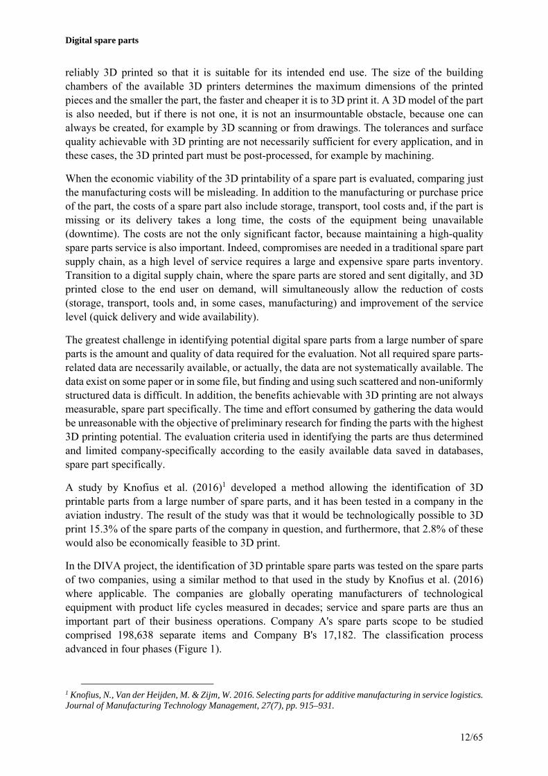
In the DIVA project, the identification of 3D printable spare parts was tested on the spare parts of two companies, using a similar method to that used in the study by Knofius et al. (2016) where applicable. The companies are globally operating manufacturers of technological equipment with product life cycles measured in decades; service and spare parts are thus an important part of their business operations. Company A's spare parts scope to be studied comprised 198,638 separate items and Company B's 17,182. The classification process advanced in four phases (Figure 1).
1 Knofius, N., Van der Heijden, M. & Zijm, W. 2016. Selecting parts for additive manufacturing in service logistics. Journal of Manufacturing Technology Management, 27(7), pp. 915–931.

Digital spare parts
13/65
Figure 1. Classification process of 3D printable spare parts.
The material and part size were used as the technological classification criteria. However, the material information was most commonly non-explicit; it was inferred from the company-specific material groupings and customs codes. The weight and dimensions were used as size data, but for the majority of the parts, this information was not easily available. The 3D model availability, tolerances, geometry, required post-processing or material properties could not be extensively commented on in the study due to the lack of systematic data.
After the first classification based on material and size, it was evident that the remaining group of spare parts still contains a lot of parts that cannot be 3D printed, and parts that could theoretically be manufactured by 3D printing, but it would not be sensible (very simple or standard part geometries). The geometry and materials (mechanical parts comprising several materials) could be better examined based on photographs in phase three. However, photographs were not available for all spare parts remaining in this phase. In the case of Company A, the sample used in the photographic analysis was around 30% of the remaining scope, and around 15% in the case of Company B. The results from the sample were extrapolated to cover the entire remaining scope of spare parts with the assumption that the parts with no photograph available are distributed into the groups printable, non-printable, or 3D printing not a feasible manufacturing method, in similar numbers as those spare parts with a photograph available. Finally, the remaining spare parts were given a rank from 1 to 7 based on the economic potential of 3D printing. Only the spare parts that were explicitly identified at item level from a photograph in phase 3 to have potential were used as the sample in the phase 4 analysis. The sample size in phase four was thus also around 30%, based on which the result was extrapolated to cover the entire remaining spare part scope. The spare part's current purchase price, re-supply lead-time, annual consumption and minimum order quantity were used as the classification criteria. Figure 2 illustrates the result obtained after each classification phase. Phase 4 was not carried out for Company B.
Figure 2. Results of the classification for the target companies.
According to the study, up to 20 to 25 per cent of spare parts at the target companies could theoretically be 3D printed. The share drops to around 5 to 6 per cent, when parts with a very simple or standard geometry are eliminated. The largest common group in the remaining set of

Digital spare parts
14/65
around five per cent comprises cast plastic and metal parts that have a reasonably complex geometry.
Finally, the economic feasibility of Company A's 3D printed spare parts was assessed, coming to the conclusion that around two per cent of the spare parts would be both technologically and economically feasible to manufacture by 3D printing. In the case of Company A, this corresponds to more than four thousand different items. When some of these items were examined in more detail, the number of economically feasible 3D printable spare parts was estimated to be even larger, if the possible savings in storage costs and the mould costs related to cast parts could have been used extensively as evaluation criteria. It is very likely that economically feasible parts could be found among the parts rejected in phase 3 due to their simple geometry, if a closer look were to be taken regarding their economic feasibility. On the other hand, it is reasonable to assume that if all technological evaluation criteria could have been used, such as tolerances and the need for post-processing, this would have correspondingly decreased the share of spare parts classified as having technological potential in this study. A new, separate group of spare parts would thus be identified in the classification: parts that can be 3D printed, but require additional measures such as post-processing or redesigning.
Companies should store information related to spare parts more comprehensively and systematically so that technologically and economically feasible 3D printable spare parts can be identified more easily, quickly and accurately in the future. Today, most spare parts do not yet have 3D models that are required at the latest when the part is 3D printed.
In recent years, Model-based Definition (MBD) has been a hot topic of discussion as the next step forward in the world of Product Lifecycle Management (PLM). Were all data related to a part to be found in a single location (3D model) saved in a structured and uniform manner in accordance with MBD, this would also make it significantly easier to identify 3D printable spare parts in the future. This particularly applies to identifying technologically feasible parts, but it would also enable making an accurate estimate of the costs of 3D printing and the manufacturing time that determines the delivery time based on the 3D model.
3D printing cost estimation tool
A tool was developed during the project for the comparison of the costs of spare parts manufactured conventionally and by 3D printing (http://amdsp.org.aalto.fi/). This cost estimation tool, developed in the MATLAB environment (MathWorks, Natick, MA, USA) is presented in Figure 3. The tool gives the user a cost and manufacturing time estimate for a metal part manufactured using powder bed fusion directly based on the STL file. The analysed part is automatically placed in the optimal position with regard to support structures, and the printing of the support structures is also included in the calculation. The user may choose which equipment manufacturer's printer or material (AlSi10Mg, tool grade steel, titanium) is used for the calculation, and manufacturing-related properties can also be adjusted. Additionally, the conventional piece, mould, storage and transport costs of the spare parts can be entered into the tool. The tool thus allows a comparison between 3D printed pieces and conventionally manufactured pieces, being particularly suitable for use with digital spare parts.

Digital spare parts
15/65
Figure 3. User interface of the tool comparing the costs and manufacturing times of 3D printing and conventional manufacturing methods.
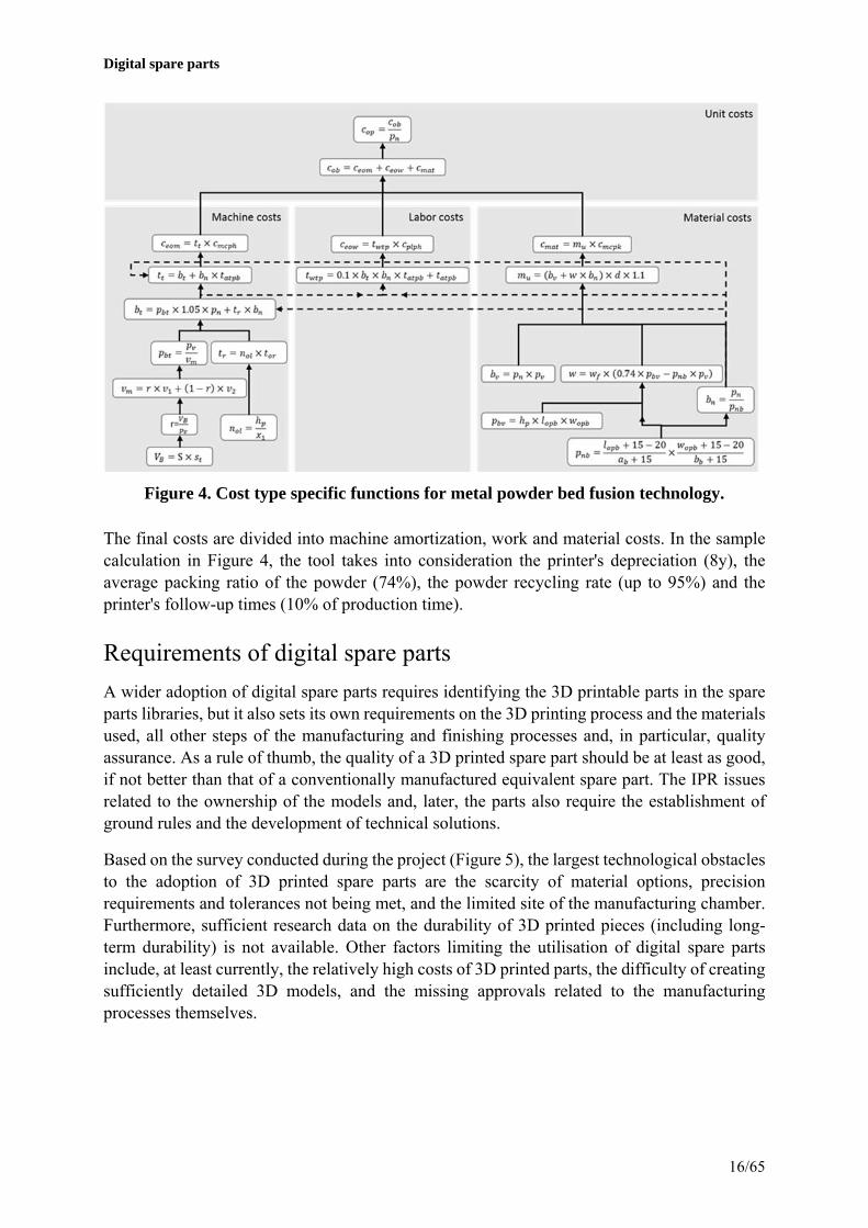
The tool outputs six diagrams based on the input data. The "SLM and CM" cost function compares the price per part between the metal powder bed fusion and conventional manufacturing technologies. The "AM and CM costs" diagram displays the part-specific and indirect costs of other 3D printing methods (material extrusion, plastic powder bed fusion, vat photopolymerization). The manufacturing cost of the conventional manufacturing method (CM) is also included in the diagram. The other diagrams include the total time function of the metal powder bed fusion process, the position of the part and the support structure, the manufacturing times of the above-mentioned manufacturing methods, and an estimate of how the part-specific costs will develop in the future. Figure 4 shows the algorithm for metal powder bed fusion as part of the cost estimation tool.
Digital spare parts
16/65
Figure 4. Cost type specific functions for metal powder bed fusion technology.
The final costs are divided into machine amortization, work and material costs. In the sample calculation in Figure 4, the tool takes into consideration the printer's depreciation (8y), the average packing ratio of the powder (74%), the powder recycling rate (up to 95%) and the printer's follow-up times (10% of production time).
Requirements of digital spare parts
A wider adoption of digital spare parts requires identifying the 3D printable parts in the spare parts libraries, but it also sets its own requirements on the 3D printing process and the materials used, all other steps of the manufacturing and finishing processes and, in particular, quality assurance. As a rule of thumb, the quality of a 3D printed spare part should be at least as good, if not better than that of a conventionally manufactured equivalent spare part. The IPR issues related to the ownership of the models and, later, the parts also require the establishment of ground rules and the development of technical solutions.
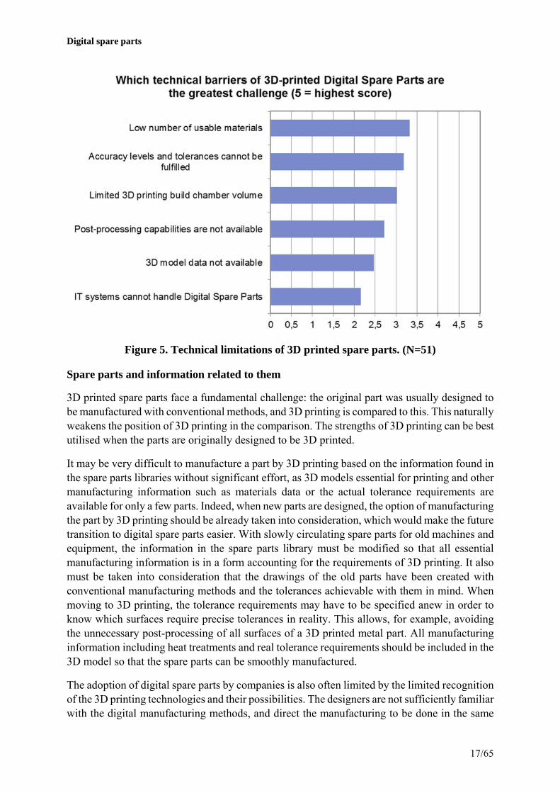
Based on the survey conducted during the project (Figure 5), the largest technological obstacles to the adoption of 3D printed spare parts are the scarcity of material options, precision requirements and tolerances not being met, and the limited site of the manufacturing chamber. Furthermore, sufficient research data on the durability of 3D printed pieces (including long-term durability) is not available. Other factors limiting the utilisation of digital spare parts include, at least currently, the relatively high costs of 3D printed parts, the difficulty of creating sufficiently detailed 3D models, and the missing approvals related to the manufacturing processes themselves.
Digital spare parts
17/65
Figure 5. Technical limitations of 3D printed spare parts. (N=51)
Spare parts and information related to them
3D printed spare parts face a fundamental challenge: the original part was usually designed to be manufactured with conventional methods, and 3D printing is compared to this. This naturally weakens the position of 3D printing in the comparison. The strengths of 3D printing can be best utilised when the parts are originally designed to be 3D printed.
It may be very difficult to manufacture a part by 3D printing based on the information found in the spare parts libraries without significant effort, as 3D models essential for printing and other manufacturing information such as materials data or the actual tolerance requirements are available for only a few parts. Indeed, when new parts are designed, the option of manufacturing the part by 3D printing should be already taken into consideration, which would make the future transition to digital spare parts easier. With slowly circulating spare parts for old machines and equipment, the information in the spare parts library must be modified so that all essential manufacturing information is in a form accounting for the requirements of 3D printing. It also must be taken into consideration that the drawings of the old parts have been created with conventional manufacturing methods and the tolerances achievable with them in mind. When moving to 3D printing, the tolerance requirements may have to be specified anew in order to know which surfaces require precise tolerances in reality. This allows, for example, avoiding the unnecessary post-processing of all surfaces of a 3D printed metal part. All manufacturing information including heat treatments and real tolerance requirements should be included in the 3D model so that the spare parts can be smoothly manufactured.
The adoption of digital spare parts by companies is also often limited by the limited recognition of the 3D printing technologies and their possibilities. The designers are not sufficiently familiar with the digital manufacturing methods, and direct the manufacturing to be done in the same

Digital spare parts
18/65
way as before. The designers may also be under the impression that the quality of 3D printed products is what it is prior to post-processing and machining, although they can significantly improve the properties of the product. Companies should now invest in the increment of 3D printing knowhow. The knowhow can be widely utilised without a direct link to the spare parts business. In the future, it will also be possible to increase the number of 3D printable spare parts through the redesigning of parts to better take into consideration the surface quality and other requirements achievable with 3D printing. For example, it is possible to eliminate some very critical tolerance requirements for connecting surfaces by manufacturing the assembly directly in a one-off process by 3D printing. In addition to tolerances, the creation of a 3D model on the basis of drawings requires information on the assembly connected to the part and strength requirements, particularly if the goal is to modify or lighten the part to better suit the 3D printing process. Naturally, one must also keep in mind that if a part is modified, it may affect the behaviour of the entire system – in effect, the designers must possess a sufficient amount of information and competence.
The next limiting factor has to do with information transfer between the different actors in the supply chain. Today, a majority of data (such as the 3D design files) are exchanged over e-mail and other manual channels. The automation level of the process should be higher in order to fully utilise the digital 3D printing process in the supply chain.
Quality and quality control
The quality of a 3D printed part is affected by, for example, the selected 3D printing process and the material used, numerous printing parameters, and various post-processing steps such as, with metal parts in particular, heat treatments, machining and finishing. Each 3D printing technology produces a slightly different structure, compactness, strength and surface quality, and comprehensive research data on these do not exist. Quality differences have also been observed between different technology groups or even pieces manufactured with the same printer.
Thus far, the only reliable method of verifying the quality of a 3D printed piece has been to print a test piece in the same run. However, the metal printing field in particular has invested extensively in developing process quality assurance. Indeed, the goal in the future should be a situation where a 3D printed spare part is printed using a certified printer, for which quality assurance methods have been developed.
Heat treatments have a great impact on the characteristics of metal parts. The microstructure of 3D printed metal parts differs from that of, for example, cast parts, due to which the heat treatment processes used most likely need to be customised in order for the quality of the end use product to match the quality of the original spare part. Automated post-processing processes should be connected to 3D printing processes so that the manufacturing of 3D printed spare parts would be profitable with respect to both time spent and cost-effectiveness. It would likely be extremely sensible if both the 3D printing and all required post-processing steps could be done in the same place. The entire manufacturing process chain would then be known already when editing the 3D model; quality control and assurance would also be simpler.

Digital spare parts
19/65
Design protection and liability issues of 3D models
It must also be possible to protect a 3D model used to print the part. Digital measures similar to those used by the music industry, for example, can be used for this. Indeed, some commercial solutions have been introduced in the field, such as Grow Software Limited's secure.AM., the 3D model linked to a product allows the part to be printed only once, for example. However, a special problem still remains: who ends up being responsible for a successful printing? If the 3D printing company is responsible, it has to buy a new 3D model if the printing is interrupted. However, if the vendor of the 3D model, or the digital spare part, is responsible, several copies of the part can be made. It is evident that only a "printing monitor" sealed into the printer can flawlessly prevent misuse.
In a digitalising world, just like the music industry, the manufacturing industry will also inevitably – regardless of their development path – run into the ease of copying and data transfer made possible by digitalisation. The challenge for businesses will be to adapt to the new situation or even create completely new businesses in the emerging market. This will involve challenges such as ensuring printing quality, the revenue logics and models of distributed printing, and taking the new operations into consideration beginning from the product development stage / data management.
Certification and liability issues
Particularly in equipment related to personal safety, the manufacturer's product liability and sometimes even the approval of various certification bodies or classification societies for new parts is required. These instances no longer concern themselves with service parts very often, but various inspection, liability and control practices determine the safety of the equipment. These practices do not often directly deal with the quality of the parts. When 3D printing starts to be used in the manufacturing of parts whose use involves personal safety, it is important to define who is liable for the deficient operation of the part, for example. It must also be considered how and with what methods the quality of the parts is defined and how it is monitored.

Digital spare parts
20/65
4. Case studies of digital spare parts The possibilities and challenges of 3D printing in the manufacturing of spare parts were analysed in more detail through demonstration pieces. The analysis performed on these demonstrations included a comparison of the conventional manufacturing method and 3D printing with regard to manufacturing costs, manufacturing speed and availability. Other factors examined included the material availability and comparability with traditional materials. Information on the demonstration pieces manufactured during the project can be found in Appendix 1, and the manufacturing process of some pieces will be described in this section.
Heated cutter
A heated cutter is a part of a wet seaming machine used in veneer manufacturing. Its task is to heat and cut the tape. The 3D model of the heated cutter is presented in Figure 6a. The cutter is heated by an internal resistor, and its sharpened edges cut the tape. During the design phase, material hardness was chosen as an important criterion in order to keep the edges sharp. The original part was manufactured from Arne tool-grade steel, which is not available for 3D printing. The manufacturing of the heated cutter was demonstrated both by using the powder bed fusion method and by 3D printing a wax model and utilising the precision casting method. The material chosen for powder bed fusion was H13 tool-grade steel and 42CrMo4 tempering steel for precision casting because the hardness of these materials would be close to Arne after heat treatments.
a) b)
Figure 6. a) 3D model of the heated cutter, b) modification made to the 3D model.
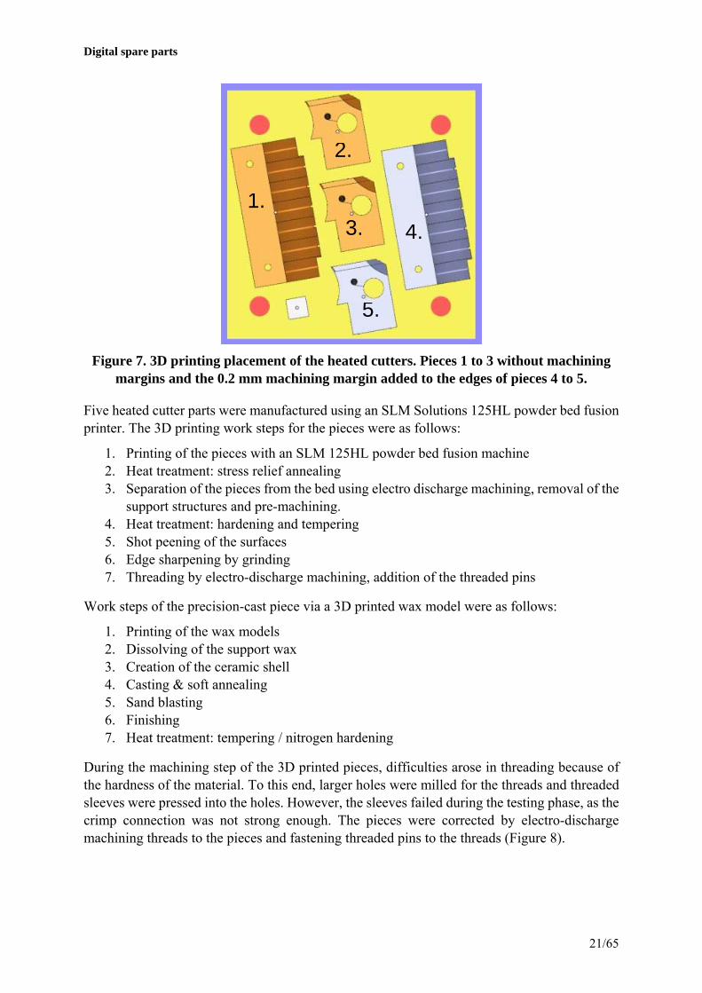
The heated cutters were 3D printed both vertically and horizontally in order to assess the possible effect of orientation on printability and performance. For some of the pieces, a 0.2 mm machining margin was added to the edges (Figure 7) which were later ground to sharp. In addition to the machining margins, the only modification made to the 3D model was the roundings of the internal channels in order to improve printability (Figure 6b). In precision casting, a machining margin of 0.2 mm was added to the top surface and the threaded holes. In addition, the lengthwise hole were removed. The wax model was also scaled up in accordance with casting shrinkage.
Digital spare parts
21/65
Figure 7. 3D printing placement of the heated cutters. Pieces 1 to 3 without machining margins and the 0.2 mm machining margin added to the edges of pieces 4 to 5.
Five heated cutter parts were manufactured using an SLM Solutions 125HL powder bed fusion printer. The 3D printing work steps for the pieces were as follows:
1. Printing of the pieces with an SLM 125HL powder bed fusion machine 2. Heat treatment: stress relief annealing 3. Separation of the pieces from the bed using electro discharge machining, removal of the
support structures and pre-machining. 4. Heat treatment: hardening and tempering 5. Shot peening of the surfaces 6. Edge sharpening by grinding 7. Threading by electro-discharge machining, addition of the threaded pins
Work steps of the precision-cast piece via a 3D printed wax model were as follows:
1. Printing of the wax models 2. Dissolving of the support wax 3. Creation of the ceramic shell 4. Casting & soft annealing 5. Sand blasting 6. Finishing 7. Heat treatment: tempering / nitrogen hardening
During the machining step of the 3D printed pieces, difficulties arose in threading because of the hardness of the material. To this end, larger holes were milled for the threads and threaded sleeves were pressed into the holes. However, the sleeves failed during the testing phase, as the crimp connection was not strong enough. The pieces were corrected by electro-discharge machining threads to the pieces and fastening threaded pins to the threads (Figure 8).
1.
2.
3.
5.
4.

Digital spare parts
22/65
Figure 8. Heated cutter at different stages of 3D printing: a) in as-built condition, b) pre-machined and heat treated, c) after shot peening and grinding, d) finished pieces.
The machining of the precision-cast pieces went without problems. After casting, the heating element hole and holes for screws were drilled. The top surface of the pieces was also machined. Next, the pieces were tempered, after which their hardness was measured at 55 HRC. A nitrogen-hardened version of the piece was also manufactured; in it, the hardness of the core material was only 43.5 HRC, but the micro-hardness of the surface increased to 59.7 HRC. The pieces after heat treatment are presented in Figure 9.
b)a)
c) d)

Digital spare parts
23/65
Figure 9. Heated cutter at different stages of precision casting: On the left, the cast piece; in the centre, the machined piece; and on the right, the machined and tempered
piece.
The manufacturing and characteristics of the original and the 3D printed piece are compared in Table 1.
Table 1. Comparison between a conventional and a 3D printed heated cutter.
Original 3D printed 3D printed wax model and precision cast
Material Arne tool grade steel H13 tool grade steel 42CrMo4 tempering steel
Annual demand 10 pcs
Manufacturing method
Mechanical machining from a flat bar
Powder bed fusion SLM Solutions 125HL
Material jetting Projet 3600W + precision casting
Post-processing Stress relief annealing Final machining Hardening and tempering Grinding
Stress relief annealing Removal of support structures Machining Hardening and tempering Grinding
Soft annealing Sand blasting Finishing Heat treatment tempering / nitrogen hardening Grinding (before nitrogen hardening)
Manufacturing speed
Machining – 12 h / 5 pcs Heat treatments – 8 h
Printing time – 34 h / 5 pcs Machining – No precise estimate Heat treatments – 10h
Printing time – 4h / 6 pcs Machining – 0.5h / pcs Heat treatments – 12h
Delivery time 3 wks 1 to 2 wks 1 to 2 wks
Manufacturing cost
€264 Printing cost ~ €110/pc. (SLM 280HL or equivalent) + machining & heat treatments
Printing cost ~ €30/pc. Precision casting ~ €15 – 60/pc. Machining ~ €90/pc. Heat treatment (€600/charge = ca. 800 kg)
Minimum batch size
1 pcs 1 pcs 1 pcs
Mechanical properties
Hardness – 58 to 60 HRC
Hardness – 48 HRC Hardness – tempered 55 HRC Nitrogen-hardened – 59.7 HRC (microhardness)

Digital spare parts
24/65
The printing costs were estimated using a separate calculation tool. The initial values used for the calculation tool were the actual material, labour and equipment costs and the process parameters (printing speed). Furthermore, the price per-piece of metal 3D printing with a medium-sized and a large powder bed fusion printer was estimated with the assumption that the printing platform is filled with pieces.
Printed metal pieces were hardened and tempered with the purpose of improving the mechanical characteristics of the material. However, the hardness of the pieces did not reach the goal (55 HRC), which points to the microstructure not being optimal. The hardness can be increased by optimising the holding times, temperatures and cooling speeds of the heat treatment. Due to the above-mentioned challenges related to machining, the manufacturing of the demonstration pieces included extraneous work steps (sleeving, electro-discharge machining) which can be avoided by soft annealing the pieces before machining.
Two metallic 3D printed, heat treated cutters were delivered to the customer for a test, where the heated cutters were installed in the top and bottom presses of a manually operated test taping machine. The testing phase was limited to a few thousand tape applications, which is a sufficient number to detect any major deficiencies. At first, 2,640 tape applications were made on wet veneer during three days, after which 1,154 tape applications were made on dry veneer during one day. The total number of 3,794 presses corresponds to around 3.5 hours of continuous running at a good pace on the right production line. During a short test, no difference whatsoever was detected in the operation of the test pieces compared to heated cutters manufactured using conventional methods.
From precision casted cutters, heat treated and nitrated were tested. 2,626 presses were made which corresponds to around 2.5hours of continuous running on the right production line. During a short test, no remarkable difference were detected when compared to heated cutters manufactured using conventional methods. Tear edges were not as sharp as traditional ones but it caused only minor effect to tear capability. It would be possible to sharpen the edges by grinding to achieve same tear marks. The nitrated one would be possible to sharpen only one time since the nitrated hard surface is quite thin. The edges would be also possible to sharpen before heat treatments.
Seat ring
A seat ring is a ring in the cylinder head of an internal combustion engine against which the valve presses when it is in the closed position. In order to guarantee tightness, the contact surfaces of the seat ring must be precisely machined. During use, the part is mostly subject to wear on the contact surfaces that are under the highest load (Figure 10a). The seat ring was chosen as a demonstration piece where the part was decided to be replaced by printing a new, top half to replace a worn-out one using the powder bed fusion technique or, alternatively, by directly depositing a new surface to the worn one.
The repair of the spare part using powder bed fusion comprised the following steps:
1. Design of the support structures 2. Removal of the worn half using electro discharge machining 3. Machining the printing platform to suit the seat ring’s bottom half

Digital spare parts
25/65
4. Printing the support structures to the printing platform 5. Printing the piece 6. Separating the support structures from the piece and the platform 7. Machining to tolerance
For directly energy deposition, the steps were as follows:
1. Pre-heating of the piece to around 500°C 2. Directed energy deposition using TIG welding – stellite 21 3. Cooling in a furnace 4. Finishing
In the powder bed fusion method, the worn part was sawn in half with an electro discharge machining at a height of 22 mm (Figure 11a), and a groove was machined into the printing platform where the part could be fitted. In order to improve printability, the original 3D model was modified so that the geometry intended to be machined was printed at an angle of 45 degrees (Figure 10b). At first, the manufacturing was attempted without support structures, but due to the high temperature gradients, the residual stresses formed in the piece were so high that they caused the piece to fracture. The piece was ultimately printed in two stages: in the first stage, support structures were created onto the platform until the height of the top surface of the part (Figure 11a), and in the second stage, the actual piece and the rest of the support structures were printed (Figure 11b). The support structures conducted heat away from the piece, so that no large residual stresses were formed. Finally, the support structures were separated (Figure 11c) and the part was machined (Figure 11d).
a) b)
Figure 10. a) The original worn seat ring, b) The modifications made to the original 3D model.

Digital spare parts
26/65
Figure 11. The seat ring manufacturing process at different stages: a) sawn piece placed on the machined printing platform, b) printed seat ring, c) support structures separated,
d) the finished piece.
In directed energy deposition, the piece was preheated to around 500°C to improve material adhesion. The preheated piece was moved to room temperature, and a generous layer of Stellite 21 material was added to the surface of the piece using the TIG welding method (Figure 12). Cooling was carried out slowly in a furnace. The hardness was measured from a reference piece, with a result of around 463 HV.
Figure 12. From Left to right: The original seat ring, the pieces after directed energy deposition, and the finished piece.
The manufacturing process and characteristics of the original and the pieces repaired using 3D printing are compared in Table 1.
a)
c) d)
b)

Digital spare parts
27/65
Table 1. Comparison of a conventional and 3D printed seat ring.
Original Powder bed fusion Directed energy deposition
Material CrNi 58/42 Inconel 718 Stellite 21
Annual consumption/replacement interval
~6,000 pcs./ 20,000–30,000 h
Manufacturing method Machining Powder bed fusion SLM Solutions 125HL
TIG welding
Post-processing Heat treatment Support removal Machining Heat treatment*
Machining
Manufacturing speed Machining – Printing time – 22.5h / 1 pc. Machining – No precise estimate
Directed energy deposition – 15 min Machining – 30 min
Delivery time 3 wks 2 wks 1 wks
Manufacturing costs €90 Printing costs ~ € /pc. – No precise estimate + machining & heat treatments * – No precise estimate
Directed energy deposition – €30 Machining – €45
Minimum batch size 75 pcs 1 pcs 1
Mechanical properties Hardness – 400 to 475 HV10
Hardness – 350 HV5 Hardness 463 HV
*The demonstration part was not heat treated
The demonstrations were used to show that the repairing of a seat ring using powder bed fusion or directed energy deposition is possible. Powder bed fusion includes numerous steps and is therefore time-consuming and requires good planning. The repair may be a potential solution with parts whose annual consumption is small and the manufacturing of which in the conventional manner would incur additional costs, for example in the form of mould manufacturing, or if the manufacturing of the part using conventional methods is expensive per se.
Mounting pin and material tests
A mounting pin is a critical component used in high temperatures that is also exposed to cyclic loads. Good strength characteristics at high temperatures are therefore required of the material. The original part was manufactured from the Inconel 718 superalloy that is also an easily available material for powder bed fusion printers. There was no existing 3D model of the mounting pin, due to which a model was created by 3D scanning of the part. The scanned model was then refined using CAD software. Three different versions of the 3D model were created: 1) threads directly from the scanned and corrected model, 2) threads created in CAD software, and 3) machining margin added in place of the threads. The manufacturing of the mounting pins comprised the following steps:
Digital spare parts
28/65
Work steps:
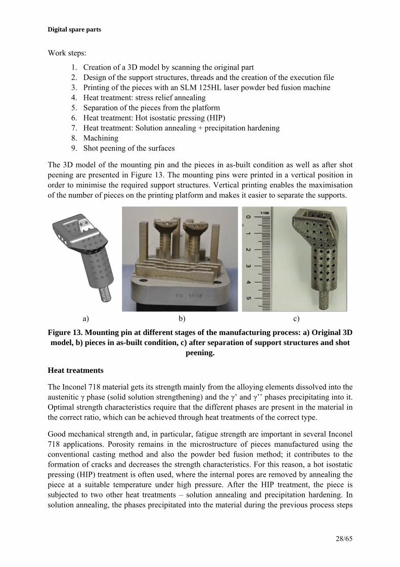
1. Creation of a 3D model by scanning the original part 2. Design of the support structures, threads and the creation of the execution file 3. Printing of the pieces with an SLM 125HL laser powder bed fusion machine 4. Heat treatment: stress relief annealing 5. Separation of the pieces from the platform 6. Heat treatment: Hot isostatic pressing (HIP) 7. Heat treatment: Solution annealing + precipitation hardening 8. Machining 9. Shot peening of the surfaces
The 3D model of the mounting pin and the pieces in as-built condition as well as after shot peening are presented in Figure 13. The mounting pins were printed in a vertical position in order to minimise the required support structures. Vertical printing enables the maximisation of the number of pieces on the printing platform and makes it easier to separate the supports.
a) b) c)
Figure 13. Mounting pin at different stages of the manufacturing process: a) Original 3D model, b) pieces in as-built condition, c) after separation of support structures and shot
peening.
Heat treatments
The Inconel 718 material gets its strength mainly from the alloying elements dissolved into the austenitic γ phase (solid solution strengthening) and the γ’ and γ’’ phases precipitating into it. Optimal strength characteristics require that the different phases are present in the material in the correct ratio, which can be achieved through heat treatments of the correct type.
Good mechanical strength and, in particular, fatigue strength are important in several Inconel 718 applications. Porosity remains in the microstructure of pieces manufactured using the conventional casting method and also the powder bed fusion method; it contributes to the formation of cracks and decreases the strength characteristics. For this reason, a hot isostatic pressing (HIP) treatment is often used, where the internal pores are removed by annealing the piece at a suitable temperature under high pressure. After the HIP treatment, the piece is subjected to two other heat treatments – solution annealing and precipitation hardening. In solution annealing, the phases precipitated into the material during the previous process steps

Digital spare parts
29/65
are dissolved evenly into the microstructure. In precipitation hardening, the phases and carbides increasing the strength of the material are precipitated into the austenitic phase.
The mounting pins were subjected to heat treatments in accordance with the ASTM standard: F3055-14a Standard Specification for Additive Manufacturing Nickel Alloy (UNS N07718) with Powder Bed Fusion. The standard defines the temperatures and soaking times for both stress relief annealing and the HIP treatment. Stress relief was carried out while the pieces were still fastened to the printing platform. The solution annealing and precipitation hardening were performed in accordance with the SAE AMS 2774 standard.
Heat treatments:
1. Stress relief annealing: 1065 °C / 1.5 h, rapid cooling in protective Ar gas. 2. HIP: 1165 °C / 4 h / 100 MPa, slow cooling along with the furnace 3. Solution annealing (in a vacuum furnace): 970 °C / 1 h, rapid cooling 4. Precipitation hardening (in a vacuum furnace): 720 °C / 8 h, cooling within 2 hours to
620 °C and treatment of 8 h, rapid cooling
Mechanical properties
In order to determine the mechanical properties, tensile test bars were printed for tensile tests and impact test bars for Charpy-V impact tests (Figure 14). The surface hardness of the samples were also measured (Vickers, HV5). The tensile tests were performed in accordance with the SFS-EN ISO 6892-1:2016 standard by using a constant elongation rate until a 2% elongation, after which a constant displacement speed was used. The measured mechanical properties are presented in Table 2. The minimum requirements for strength properties specified in the ASTM F3055-14a standard were used as a reference.
a) b)
Figure 14. 3D printed a) Charpy-V impact test bars, b) tensile test bars.

Digital spare parts
30/65
Table 2. Results of the tensile tests, hardness measurements and impact tests (average ± standard deviation).
Number of samples
Heat treatment
Elastic modulus (Gpa)
Yield strength, Rp0.2 (Mpa)
Tensile strength, Rm (Mpa)
Elongation at fracture (%)
Hardness (HV5)
Charpy-V energy of fracture (J)
2 pcs Stress relief 205 ± 6 864 ± 53 1130 ± 15 14 ± 7 394 ± 5
2 pcs Stress relief + HIP
213 ± 6 827 ± 1 1121 ± 2 20 ± 1 295 ± 3 42 ± 8
3 pcs Stress relief + HIP + Solvent annealing + Precipitation hardening
207 ± 8 1153 ± 18 1331 ± 12 9 ± 1 448 ± 6 17 ± 8
Reference ASTM F3055-14a (Class D)
≥940 ≥1240 ≥12
After the final heat treatments, the 3D printed pieces have a high strength, but their elongation at fracture falls slightly short of the minimum requirement of the standard.
Microstructure
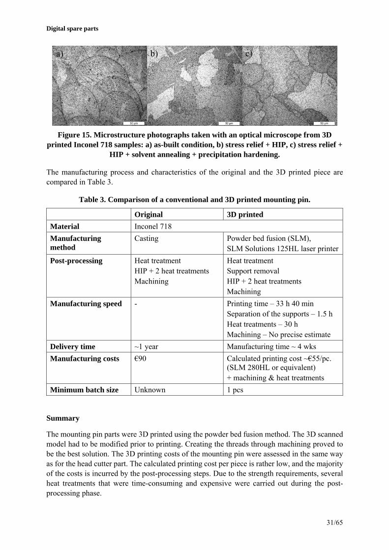
For the purpose of examining the microstructure, three 1×1×3cm³ bars were printed. Sections of the bars were prepared for a microstructure analysis performed with optical and scanning electron microscopes. One bar was left at as-built condition and two bars were heat treated with one subjected to stress relief + HIP treatment and the other also subjected to solvent annealing and precipitation hardening. The samples were etched prior to the microscopic examination. Pictures of the samples before and after etching are presented in Appendix2. Based on the photographs taken of the sections, it can be stated that the porosity could be eliminated with the HIP treatment.
The microstructure photograph of the sample in as-built condition (Figure 15a) shows the solidified meltpools resulting from the laser melting process. After the stress relief and HIP treatment (Figure 15b), grain size increase and a more homogeneous grain structure is evident. The difference caused by the solvent annealing and precipitation hardening in the microstructure is difficult to see in the microstructure image (Figure 15c), due to which the samples were also examined with a scanning electron microscope (SEM). The images of the samples are compiled in Appendix 3.
The examination of the heat-treated (solvent + precipitation) sample using an SEM revealed that the γ’ phase has evenly precipitated into the microstructure; additionally, carbides and precipitates were also detected in the metal matrix and grain boundaries, which are likely of the delta phase. The demonstration part was only subjected to a quick overview and the determination of the phase ratios would require further study.
Digital spare parts
31/65
Figure 15. Microstructure photographs taken with an optical microscope from 3D printed Inconel 718 samples: a) as-built condition, b) stress relief + HIP, c) stress relief +
HIP + solvent annealing + precipitation hardening.
The manufacturing process and characteristics of the original and the 3D printed piece are compared in Table 3.
Table 3. Comparison of a conventional and 3D printed mounting pin.
Original 3D printed
Material Inconel 718
Manufacturing method
Casting Powder bed fusion (SLM), SLM Solutions 125HL laser printer
Post-processing Heat treatment HIP + 2 heat treatments Machining
Heat treatment Support removal HIP + 2 heat treatments Machining
Manufacturing speed - Printing time – 33 h 40 min Separation of the supports – 1.5 h Heat treatments – 30 h Machining – No precise estimate
Delivery time ~1 year Manufacturing time ~ 4 wks
Manufacturing costs €90 Calculated printing cost ~€55/pc. (SLM 280HL or equivalent) + machining & heat treatments
Minimum batch size Unknown 1 pcs
Summary
The mounting pin parts were 3D printed using the powder bed fusion method. The 3D scanned model had to be modified prior to printing. Creating the threads through machining proved to be the best solution. The 3D printing costs of the mounting pin were assessed in the same way as for the head cutter part. The calculated printing cost per piece is rather low, and the majority of the costs is incurred by the post-processing steps. Due to the strength requirements, several heat treatments that were time-consuming and expensive were carried out during the post-processing phase.
a) b) c)
Digital spare parts
32/65
The mechanical properties of the 3D printed spare parts exceeded the minimum requirements with the exception of elongation at fracture that fell slightly short of the target. In summary, it can be stated, however, that the standard-compliant heat treatment performed on the 3D printed samples gave good results. However, because this is a critical component, the adoption of a 3D printed spare part would require validation including extensive testing at operating temperatures.
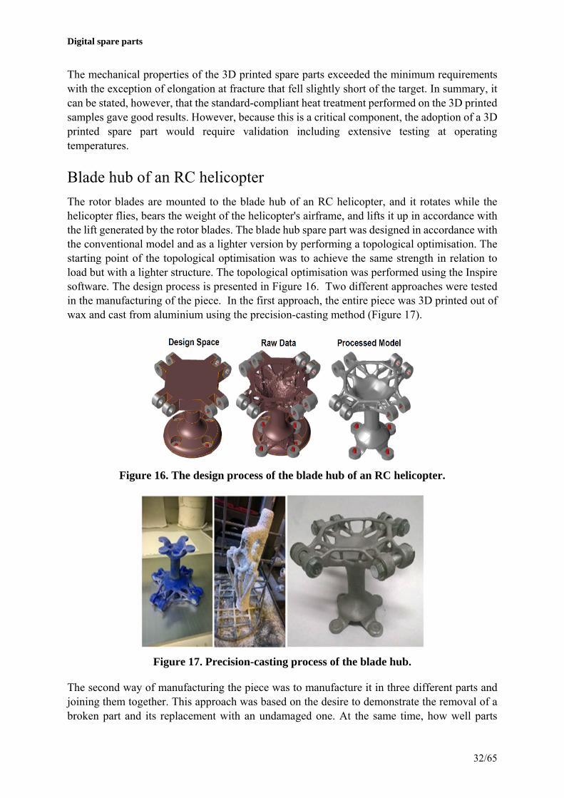
Blade hub of an RC helicopter
The rotor blades are mounted to the blade hub of an RC helicopter, and it rotates while the helicopter flies, bears the weight of the helicopter's airframe, and lifts it up in accordance with the lift generated by the rotor blades. The blade hub spare part was designed in accordance with the conventional model and as a lighter version by performing a topological optimisation. The starting point of the topological optimisation was to achieve the same strength in relation to load but with a lighter structure. The topological optimisation was performed using the Inspire software. The design process is presented in Figure 16. Two different approaches were tested in the manufacturing of the piece. In the first approach, the entire piece was 3D printed out of wax and cast from aluminium using the precision-casting method (Figure 17).
Figure 16. The design process of the blade hub of an RC helicopter.
Figure 17. Precision-casting process of the blade hub.
The second way of manufacturing the piece was to manufacture it in three different parts and joining them together. This approach was based on the desire to demonstrate the removal of a broken part and its replacement with an undamaged one. At the same time, how well parts
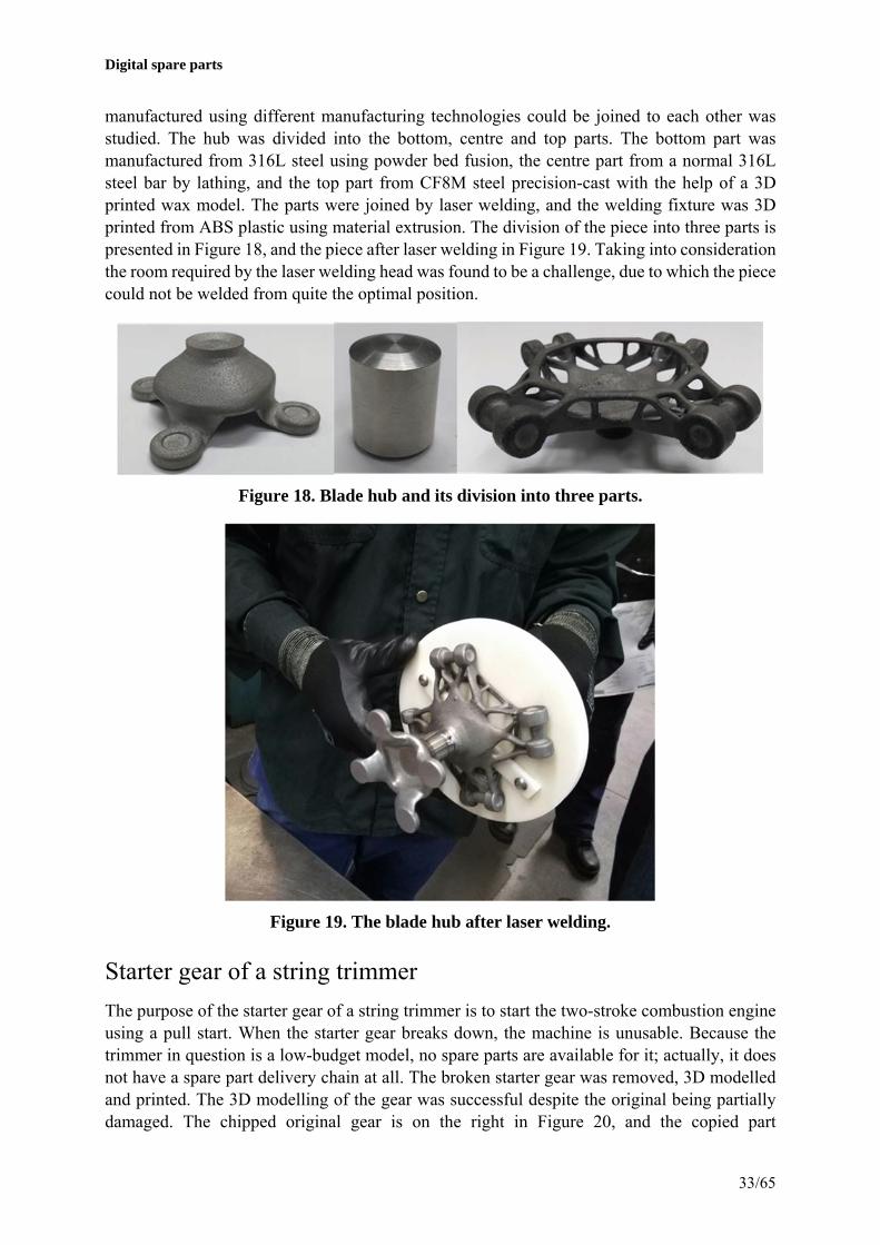
Digital spare parts
33/65
manufactured using different manufacturing technologies could be joined to each other was studied. The hub was divided into the bottom, centre and top parts. The bottom part was manufactured from 316L steel using powder bed fusion, the centre part from a normal 316L steel bar by lathing, and the top part from CF8M steel precision-cast with the help of a 3D printed wax model. The parts were joined by laser welding, and the welding fixture was 3D printed from ABS plastic using material extrusion. The division of the piece into three parts is presented in Figure 18, and the piece after laser welding in Figure 19. Taking into consideration the room required by the laser welding head was found to be a challenge, due to which the piece could not be welded from quite the optimal position.
Figure 18. Blade hub and its division into three parts.
Figure 19. The blade hub after laser welding.
Starter gear of a string trimmer
The purpose of the starter gear of a string trimmer is to start the two-stroke combustion engine using a pull start. When the starter gear breaks down, the machine is unusable. Because the trimmer in question is a low-budget model, no spare parts are available for it; actually, it does not have a spare part delivery chain at all. The broken starter gear was removed, 3D modelled and printed. The 3D modelling of the gear was successful despite the original being partially damaged. The chipped original gear is on the right in Figure 20, and the copied part
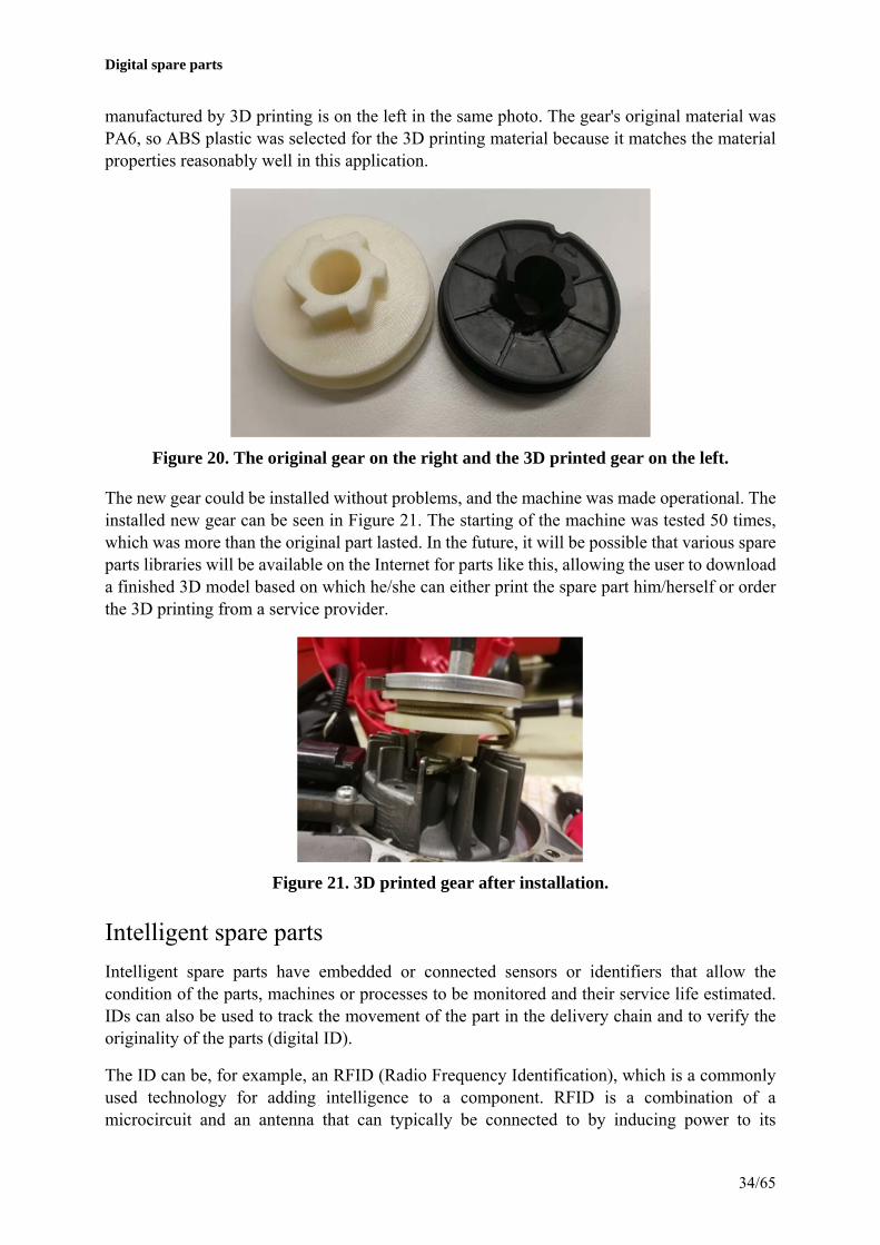
Digital spare parts
34/65
manufactured by 3D printing is on the left in the same photo. The gear's original material was PA6, so ABS plastic was selected for the 3D printing material because it matches the material properties reasonably well in this application.
Figure 20. The original gear on the right and the 3D printed gear on the left.
The new gear could be installed without problems, and the machine was made operational. The installed new gear can be seen in Figure 21. The starting of the machine was tested 50 times, which was more than the original part lasted. In the future, it will be possible that various spare parts libraries will be available on the Internet for parts like this, allowing the user to download a finished 3D model based on which he/she can either print the spare part him/herself or order the 3D printing from a service provider.
Figure 21. 3D printed gear after installation.
Intelligent spare parts
Intelligent spare parts have embedded or connected sensors or identifiers that allow the condition of the parts, machines or processes to be monitored and their service life estimated. IDs can also be used to track the movement of the part in the delivery chain and to verify the originality of the parts (digital ID).
The ID can be, for example, an RFID (Radio Frequency Identification), which is a commonly used technology for adding intelligence to a component. RFID is a combination of a microcircuit and an antenna that can typically be connected to by inducing power to its

Digital spare parts
35/65
microcircuit via the antenna. Other IDs include various bar codes and matrix patterns. Some basic information on the part can be embedded into the ID, but external data sources must be used for the processing of larger amounts of data. The ID can be physically connected to the component in many different ways.
Product data can be stored into the microcircuit, or real-time data can be produced with the connected sensors. In this way, the "intelligence" of the component can be increased by combining, storing, reading or writing information in an external database for the component.
3D printing enables manufacturing the internal structures of a part due to the layer by layer manufacturing principle. This kind of an internal structure can be, for example, a cavity into which the above-mentioned ID or sensors can be installed either manually or by using other manufacturing methods such as directed energy deposition while the manufacturing is halted.
Four different 3D printing technologies were used in the demonstration for converting the starter gear into an intelligent spare part. The 3D printing methods used were vat photo-polymerization (Form2 / Formlabs), material extrusion (uPrint / Stratasys), powder bed fusion (SLS printer, built by Aalto University) and binder jetting (Zprinter / 3D Systems). Each technology was used to print a spare part into which an RFID circuit was embedded (Figure 22). A link to the part's manufacturing documentation that was stored on a file server was saved into the RFID as attribute data. The reader software was set up to open the link in question at the time of reading (Figure 23).
Figure 22. Intelligent spare parts created using four different 3D printing technologies.

Digital spare parts
36/65
Figure 23. Reference picture of the reading of an intelligent spare part and linking to an external information system.
Electronics enclosure
The replacement of an injection-moulded electronics enclosure was demonstrated with a plastic powder bed fusion technology. A copy was modelled of the original enclosure and manufactured by 3D printing from the PA12 material. The original enclosure and its 3D printed copy are presented in Figure 24 .
Figure 24. Injection-moulded electronics enclosure on the left and the selective laser-sintered enclosure on the right.
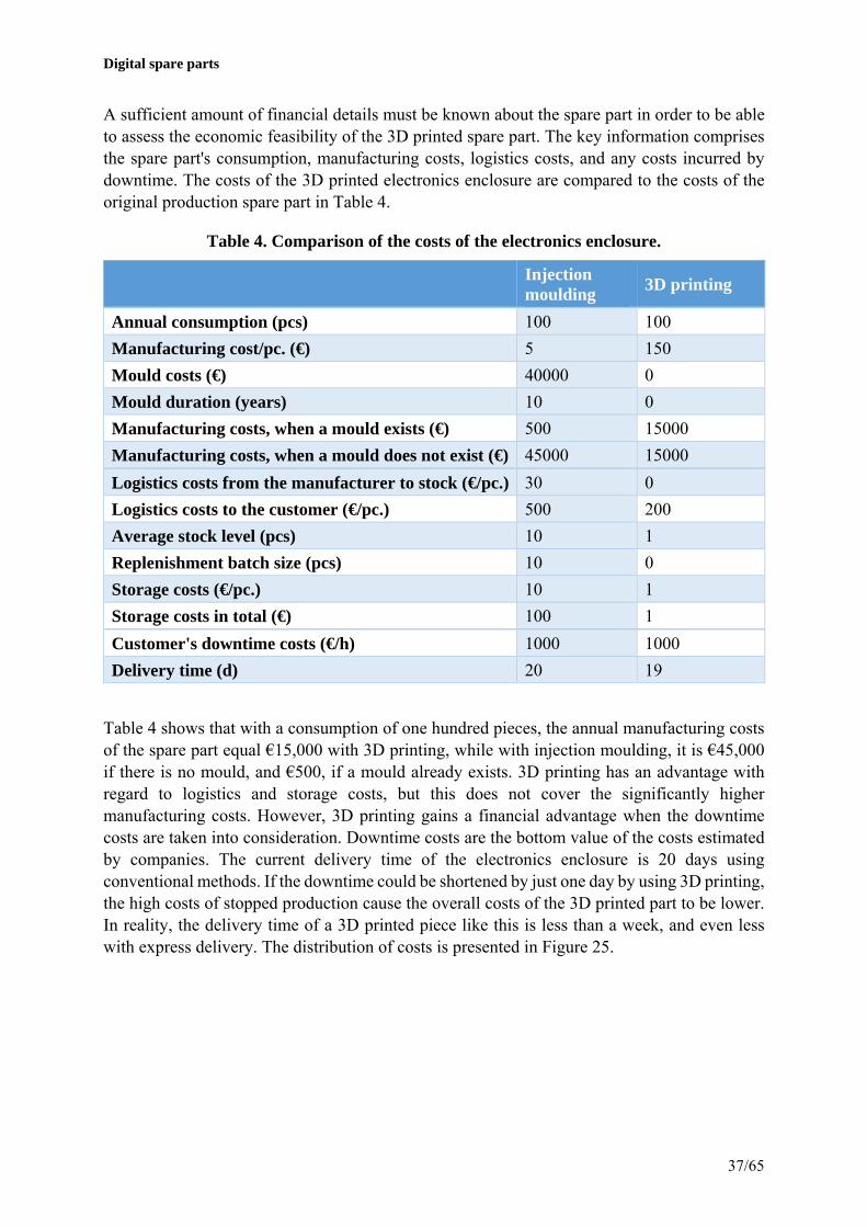
Digital spare parts
37/65
A sufficient amount of financial details must be known about the spare part in order to be able to assess the economic feasibility of the 3D printed spare part. The key information comprises the spare part's consumption, manufacturing costs, logistics costs, and any costs incurred by downtime. The costs of the 3D printed electronics enclosure are compared to the costs of the original production spare part in Table 4.
Table 4. Comparison of the costs of the electronics enclosure.
Injection moulding
3D printing
Annual consumption (pcs) 100 100
Manufacturing cost/pc. (€) 5 150
Mould costs (€) 40000 0
Mould duration (years) 10 0
Manufacturing costs, when a mould exists (€) 500 15000
Manufacturing costs, when a mould does not exist (€) 45000 15000
Logistics costs from the manufacturer to stock (€/pc.) 30 0
Logistics costs to the customer (€/pc.) 500 200
Average stock level (pcs) 10 1
Replenishment batch size (pcs) 10 0
Storage costs (€/pc.) 10 1
Storage costs in total (€) 100 1
Customer's downtime costs (€/h) 1000 1000
Delivery time (d) 20 19
Table 4 shows that with a consumption of one hundred pieces, the annual manufacturing costs of the spare part equal €15,000 with 3D printing, while with injection moulding, it is €45,000 if there is no mould, and €500, if a mould already exists. 3D printing has an advantage with regard to logistics and storage costs, but this does not cover the significantly higher manufacturing costs. However, 3D printing gains a financial advantage when the downtime costs are taken into consideration. Downtime costs are the bottom value of the costs estimated by companies. The current delivery time of the electronics enclosure is 20 days using conventional methods. If the downtime could be shortened by just one day by using 3D printing, the high costs of stopped production cause the overall costs of the 3D printed part to be lower. In reality, the delivery time of a 3D printed piece like this is less than a week, and even less with express delivery. The distribution of costs is presented in Figure 25.

Digital spare parts
38/65
Figure 25. Distribution of costs of the electronics enclosure.

Digital spare parts
39/65
5.The impact of digital spare parts on operating models and systems
Network and business models
The impact of digital spare parts on operating models can be conceptualised with the help of the five general supply chain models developed in the project, varying from a centralised to a distributed model (Figure 26): 1) OEM-centric model 2) Maintenance service provider centric model 3) 3D database operator centric model 4) 3D printing service provider centric model 5) End user centric model.
Figure 26. Five supply chain models.
The OEM-centric model (Figure 27) is suitable for situations such as ones involving major liability issues, such as safety-critical applications (e.g. medical equipment and aviation). In this model, IPR management is clear as the OEM controls the entire process. However, there is the question of whether this is the OEM's core competence. For the end user, this model is easy and reliable, albeit an inflexible model, because there are no alternative channels for transacting business.
Figure 27. OEM-centric model.
The maintenance service provider centric model (Figure 28) is particularly suitable for situations where the maintenance service provider has traditionally had a strong customer relationship with the end user, for example machines and equipment that require constant and regular maintenance. Additionally, the maintenance service provider is often geographically closer to the end user than the OEM, which makes co-operation easier.

Digital spare parts
40/65
Figure 28. Maintenance service provider centric model.
3D database operator centric model (Figure 29) can be seen as the most disruptive model, where an entirely new actor steps into a key role in the network. This role could also be suitable for some major global platform operator (e.g. Google, Amazon or eBay). In this model, the end user could access the spare part selection of many different OEMs through one 3D database operator. In this model, the end user is clearly more proactive than in the two previous models. For example, the end user is responsible for quality assurance and certain maintenance operations, so this model requires more expertise from the end user than the previous models.
Figure 29. 3D database operator centric model.
In a 3D printing service provider centric model (Figure 30), a conventional manufacturing company or component supplier can also play a key role. These actors likely have already some of the manufacturing process (such as the post-processing equipment), so the transition could be quite organic. The idea is that the end user aims to choose the actor that is geographically as close as possible. If there are several 3D printing service providers, their comparison can be challenging to the end user.

Digital spare parts
41/65
Figure 30. 3D printing service provider centric model.
The end user centric model (Figure 31) could well be described as a do-it-yourself distributed model, where the end user has a lot of power and choice. This model is mainly suitable for non-critical applications and generic spare parts. The model is fast and flexible for the end user, but also requires a lot of technical expertise and access to the required equipment. This model was seen to be best suited to the B2C market context.
Figure 31. End user centric model.
As a business, 3D printing is still taking its baby steps. Therefore, no clear dominating value chain models and networks are yet evident. As an example, many printing service companies involved in the project stated that they are operating customer-specifically via networks of various types, and this was not expected to change in the near future. Companies are thus still trying out different operating models to find what works. OEMs have no clear network model of the future, either, but the business logic must be constantly reassessed as the printing and scanning technologies develop.
Many companies are contemplating whether to focus on and invest in 3D printing technology. The factors holding up acquisitions are often seen to be the fact that the technology is still in a rapid development and reinvention phase and, on the other hand, the capacity obtained from a possible investment could not be utilised to a sufficiently large extent. These factors would

Digital spare parts
42/65
seem to point to 3D printing seeing progress in the near future particularly through the actions of specialised printing companies. This allows the centralised building of expertise and the achievement of a higher utilisation rate for the investments through a wider customer base.
Co-operation, competencies and management
Co-operation between different actors of the network related to 3D printed spare parts is currently relatively light, but its importance is estimated to increase in the future. As a rule, co-operation between the different actors is smooth. Problems will arise mainly due to delays in schedules and insufficient communications.
The problems in co-operation related to ordering, printing and the transport phase can mainly be reduced through active communications, functional negotiation relationships and quick reactions. Clear agreements, automation of the co-operation and electronic systems that create transparency to the partner network will improve the situation. In systematic and wide-scale operations with large customer companies in particular, functional Web systems will be required in the future, specifically for order management, instead of orders being placed via e-mail, for example. Co-operation also requires trust. Trust can be increased by, for example, agreements (NDA), limiting the contents if information is shared, and co-operation between actors who are already known and those found to be reliable.
The digitalisation of spare part production will radically change the competencies required of the companies. The importance of routine tasks would appear to decrease, while more demanding data-based tasks will increase in importance. The competencies required of the companies vary depending on their role in the digital spare parts network. The competencies can be divided into three categories, the first of which is connected to the general understanding of the 3D printing process. The second category includes commercial and business competence. It includes project management skills, logistics competence, delivery time management, legal knowledge (NDA), and skills in marketing and pricing. The third and last category includes social skills, meaning co-operation and communication skills, management skills and an ability for creative thinking.
Managing co-operation requires a shared view of the goals and tasks. The progress of the process must be transparent, which means open information sharing and rapid reaction to any problems and changes. With established co-operation partners, regular follow-up meetings, for example, will allow the prevention of problems and the building of trust.
ICT systems
Today, 3D printing is one alternative method of manufacturing the required part for Finnish companies. The chain of events related to the manufacturing of a 3D printed part is rather straightforward. Typically, the communications and information exchange related to the 3D printing of a spare part takes place by e-mail. The customer sends the model of the part to be printed either as a finished 3D model, a scan, or a paper drawing. Information on the part is delivered either as an e-mail attachment or as a link to the customer's document management system, as are any work or material instructions. In some cases, the actors in the supply network

Digital spare parts
43/65
have some access to each other's systems within the supply chain, but only to a very limited extent.
The customer may also only have a broken part for which there are no drawings whatsoever. In these cases, reverse engineering methods can be used involving either scanning of the broken part and editing the model to the necessary extent, or using an external partner for the CAD modelling of the part.
In time, there may also be several revisions of the parts, in which case the version management is typically done by using file naming practices. The storage and back-up copies of the 3D models are typically done using a third-party cloud service. The CAD system models are usually saved in the native format, and the converted STL models used in 3D printing are not usually collected in information systems.
The IPR of the models created of the parts is almost by default owned by the customer, i.e., the party who placed the order. Some of the customers require the deletion of the created model after printing, while some ask the printer to save the model for a possible later need. Customers of 3D printing companies were rarely interested in the issues related to the ownership or use of the created 3D model, only for the physical part obtained as the result.
To date, companies have not thus needed special investments related to the 3D printing information systems. They mostly use various CAD software for part design and creation of 3D models, and systems required for the operation of the 3D printer and planning the production.
From the perspective of information systems science, 3D printing can be considered to be one of the technologies enabling the digitalisation of production processes – it allows a more efficient customisation of products and a distributed production. In order to maximise the obtainable benefit, the production processes related to 3D printing should be digital to the greatest possible extent. In order to be able to manufacture a 3D printed part economically and with uniform quality in a distributed environment, all data related to the product specifications should be available in a digital format.
An increasing amount of manufacturing process-related data in usable format is available as the production becomes more digital, such as specifications, designs and measurement data. With suitable data management solutions, data related to the 3D printing process could be utilised by the companies much more efficiently than today, and new business opportunities could even be created based on it.
In the future, the stronger integration of the customers into the development and manufacturing of the 3D printable product will generate added value for the supply network. The amount of data generated during the manufacturing process will increase greatly, and this data could be utilised much more diversely than today, such as in product validation or in the simulation of its functionality. Information exchange should be increased both between the end user/customer and product development, and between product development and manufacturing. The digital model of a part or a product should contain all data essential to its high-quality manufacturing. Over the life cycle of a product, a "digital thread" is formed: all information related to the design, manufacturing and use of the part is gathered in digital form. The digital thread enables the sharing of the information within the organisation, with the members of the production networks, customers and end users. By adding its visibility in this way, the production network

Digital spare parts
44/65
will be able to make its operations more efficient and more automated, and to provide better service to the end user. A "digital twin" of the product or part is formed of all the gathered data that can be utilised in the further development of the product and production, and in the development of new business models.
As the amount of data constantly increases, the importance of information security is emphasised. As a rule, the copying and distribution of digital data is easy, so copyright protection and prevention of pirating will play an important role. In a similar vein, the correctness and integrity of the data are essential issues: a malicious actor could make changes to the 3D model of a spare part, making its structure dangerously weak. There are also open questions related to product safety: which member in the supply chain will be liable if the printed spare part breaks and causes a hazardous situation?

Digital spare parts
45/65
6. Future of digital spare parts
Development of 3D printing – forecast
According to forecasts on 3D printers, the size of their building chambers will increase, their material selection will become wider, and their printing processes will become more efficient. Table 5 shows that as early as in the next couple of years, the majority, or around 81 to 99%, of the 3D printable spare parts could be manufactured by 3D printing with respect to their size, depending on the printing process used.
Table 5. Chamber volume today and in 2020, and the shares of pieces that fit into the printers.
Largest building chamber volume
in 2017 [m3]
Share of pieces that fit into the printer in 2017
[%]
Estimated largest building chamber volume
in 2020 [m3]
Share of pieces that fit into the printer in 2020
[%]
Powder bed fusion (metal)
0.16 63.34 0.52 81.07
Binder jetting 0.3 72.25 0.7 86.27
Material jetting 0.4 76.73 0.8 88.7
Vat photo-polymerization
0.62 84.11 1.5 99
Powder bed fusion (plastic)
0.98 92.56 2.4 99
Sheet lamination 3 99 4.2 99
Binder jetting (sand) 8 99 11.5 99
Directed energy deposition
11.7 99 16 99
Material extrusion 25 99 25 99
The production speeds of 3D printing methods suitable for the manufacturing of industrial parts is expected to increase significantly over the next decade (Figure 32). A survey targeted at research institutes shows that the material extrusion technology is expected to achieve a manufacturing speed of 25,000 cm3/h in 2028, plastic-based binder jetting 10,000 cm3/h in 2025, and sand-based binder jetting to achieve a comparable manufacturing speed in 2028. Plastic-based powder bed fusion will achieve a manufacturing speed of 2,000 cm3/h after 2023, while metal-based powder bed fusion will achieve a manufacturing speed of 200 cm3/h after 2025.

Digital spare parts
46/65
Figure 32. Forecast of the development of the build speeds of 3D printers.
The increase in the size of the building chambers, the higher production speeds and the decrease in the prices of printing materials will likely significantly decrease the prices of 3D printed parts within the next couple of years. Figure 33 presents the future cost development of 3D printing as a function of time until year 2025. The Y axis shows the decrease of the per-part production costs of the sample geometry (timing wheel, volume 80 cm3). As the material and machine costs both decrease by 60%, the final costs may decrease by as much as 55%. According to our estimate, the most likely future scenario is that by 2025, the material costs will decrease by 60% while the machine costs remain unchanged, due to which the overall costs will decrease by 32%. The increasing competition and the increasing number of metal printers will presumably also lower the prices. Only a few companies are able to produce high-end metal 3D printers intended for the production of high-quality pieces. Due to this and regardless of the 60% drop in material costs, the machine costs may remain at the same level as before. Further improvements in production speed can be achieved, due to which the overall costs could potentially decrease by 40 to 45% by 2025.

Digital spare parts
47/65
Figure 33. Decrease of manufacturing costs as a function of time for the sample geometry.
Future outlook of digital spare parts
Digital spare parts involve many factors, and their development and readiness will largely determine how soon and to what extent companies will adopt digital spare parts. The most important factors are likely to be the development of the materials, 3D printing costs and the quality of 3D printed pieces, and their comparability with conventionally manufactured parts. The automation of the process is also essential for the cost-effectiveness of the process. Automation is required in both the order and delivery processes at the different phases of the manufacturing chain related to 3D printing.
The selection of 3D printing materials is constantly growing and the costs of 3D printing are decreasing, which will likely accelerate the adoption and utilisation of digital spare parts. 3D printing will also soon establish its foothold in the manufacturing of the originally delivered parts. Some of the spare parts will thus naturally become digital spare parts. The digitalisation of spare parts allows the constant updating of parts, due to which the availability of spare parts will be better in the future as well as customised according to the needs of the application. This

Digital spare parts
48/65
also applies to assemblies of which only the broken parts can be printed or, on the other hand, multiple-part assemblies can be printed in one go.
More comprehensive quality systems must be developed for digital spare parts. It must be possible to guarantee and verify that the performance and quality of parts manufactured with 3D printing processes are at a minimum equal to those of parts manufactured with conventional methods. Spare part libraries also require updating: in addition to 3D models, the libraries should include all manufacturing data including tolerances, materials data and the required post-processing. It is likely that various ecosystems will be built around digital spare parts in the future, where both manufacturing data and the 3D printed spare parts move securely between the different actors. It is also highly likely that digital spare parts will bring new actors into the ecosystems, such as companies that convert spare part models and their manufacturing data into a digital format and possibly also store and transmit data related to the spare parts between the different actors in the ecosystem. Digital spare parts can be manufactured in a distributed manner which shortens the supply chain, reduces the number and loss of parts unnecessarily manufactured for local stores, and decreases the need to transport parts.
Spare part concepts of the future
3D printing will create numerous new possibilities in the future. The 3D printed part does not necessarily need to be a direct copy of the original part; the part can be customised as necessary – for example, intelligence can be embedded into it, or the part can be designed to last only for a limited time (so-called first aid spare parts). Parts can also be repaired using 3D printing, or they can be manufactured in, for example, mobile 3D printing stations. The different spare part concepts of the future made possible by 3D printing are depicted in Table 6.
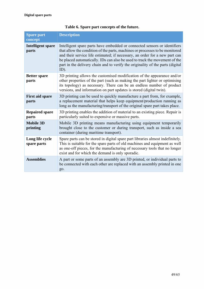
Digital spare parts
49/65
Table 6. Spare part concepts of the future.
Spare part concept
Description
Intelligent spare parts
Intelligent spare parts have embedded or connected sensors or identifiers that allow the condition of the parts, machines or processes to be monitored and their service life estimated; if necessary, an order for a new part can be placed automatically. IDs can also be used to track the movement of the part in the delivery chain and to verify the originality of the parts (digital ID).
Better spare parts
3D printing allows the customised modification of the appearance and/or other properties of the part (such as making the part lighter or optimising its topology) as necessary. There can be an endless number of product versions, and information on part updates is stored (digital twin).
First aid spare parts
3D printing can be used to quickly manufacture a part from, for example, a replacement material that helps keep equipment/production running as long as the manufacturing/transport of the original spare part takes place.
Repaired spare parts
3D printing enables the addition of material to an existing piece. Repair is particularly suited to expensive or massive parts.
Mobile 3D printing
Mobile 3D printing means manufacturing using equipment temporarily brought close to the customer or during transport, such as inside a sea container (during maritime transport).
Long life cycle spare parts
Spare parts can be stored in digital spare part libraries almost indefinitely. This is suitable for the spare parts of old machines and equipment as well as one-off pieces, for the manufacturing of necessary tools that no longer exist and for which the demand is only sporadic.
Assemblies A part or some parts of an assembly are 3D printed, or individual parts to be connected with each other are replaced with an assembly printed in one go.
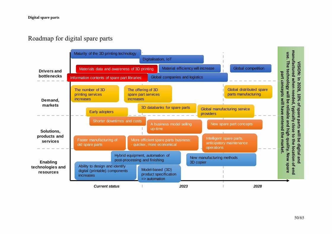
Digital spare parts
50/65
Roadmap for digital spare parts
VISION: In 2028, 10%
of spare parts will be digital and
manufactured w
hen needed, typically close to the location of end use. The technology w
ill be reliable and high quality. New
spare part concepts w
ill have entered the market.
Solutions, products and
services
Enabling technologies and
resources
Current status
Drivers and bottlenecks
2023 2028
Demand, markets
Ability to design and identify digital (printable) components increases
Shorter downtimes and costs
3D databanks for spare parts
Maturity of the 3D printing technology
Information contents of spare part libraries
Faster manufacturing of old spare parts
A business model selling up-time
More efficient spare parts business: - quicker, more economical
Intelligent spare parts, anticipatory maintenance operations
New spare part concepts
Hybrid equipment, automation of post-processing and finishing
New manufacturing methods 3D copier
Global companies and logistics
Material efficiency will increaseMaterials data and awareness of 3D printing
Digitalisation, IoT
Global competition
The number of 3D printing services increases
Early adopters
Global distributed spare parts manufacturing
Global manufacturing service providers
The offering of 3D spare part services increases
Model-based (3D) product specification => automation

Digital spare parts
51/65
7. Summary Digital spare parts is a concept where the spare parts and the related manufacturing data are stored and transferred in digital form. The spare parts are manufactured using 3D printing according to need, usually close to the end user’s premises. The digitalisation of spare parts aims for a better, more flexible and quicker availability of spare parts, and lower storage, manufacturing and transport costs. The quicker delivery of spare parts can also reduce downtime, which can mean significant cost savings.
It is essential in the digitalisation of the companies' spare parts to find the parts in the spare part libraries that bring the greatest benefit when they are stored in digital form and manufactured by 3D printing. Such parts include, in particular, parts of old equipment and machines and slowly circulating parts with complex geometries. Today, 3D printing can be used to manufacture high-performance pieces, and the method is excellently suited to the manufacturing of individual pieces or short-run batches; it also allows the improvement of the spare parts, with updated and intelligent spare parts as examples.
Information on a company's spare parts is scattered between multiple systems, and manufacturing data in particular may be difficult to find. At the initial stage, it is important to identify the 3D printable parts in the spare part libraries and digitalise them, not only with regard to 3D models but all other manufacturing data from materials and tolerances to the required post-processing data. The digitalisation of spare parts requires 3D design competence, knowledge of the 3D printing processes, and familiarisation with the printable materials.
Spare parts are rarely designed to be manufactured by 3D printing; on the other hand, the selection of 3D printable materials remains reasonably limited, due to which situations where a part is manufactured from a replacement material will likely occur. 3D printing processes produce their own kind of a structure and surface finish, due to which the post-processing of 3D printable parts, such as heat treatments and finishing, must be carefully chosen. The goal is that the properties of parts manufactured by 3D printing are at least as good as those of conventionally manufactured parts.
The vision of the roadmap for digital spare parts presented in the report is that after ten years or so, 10% of spare parts are digital, and the manufacturing technology is reliable and is of a high quality. In other words, quality verification, the extension of the related material selection and the automation of processes are required of the 3D printing technologies.
3D printing creates new possibilities for the development of the operation of parts, equipment or entire processes. IDs and sensors can be embedded into 3D printed parts, allowing the tracking of their movement in the supply network and anticipatory condition monitoring. A spare part of the future will be able to automatically order a new part from a digital spare part library so that it can be replaced by the new part just at the right time before the machine breaks down or the process stops.

Digital spare parts
52/65
8. Appendices

Digital spare parts
53/65
Appendix 1. Demonstration parts of the digital spare parts project. Picture of the piece Name Spare part
category Material (original)
Material (demo)
Available data Manufacturing method (original)/ post-processing
Manufacturing method (demo)/ post-processing
Heated cutter
Direct replacement spare part / updated spare part
ARNE tool grade steel
H13 tool grade steel
3D model, 2D drawing
Machined from a flat bar, finishing grinding,
heat treatment
SLM, machining, heat treatment, finishing grinding
Heated cutter
Direct replacement spare part / updated spare part
ARNE tool grade steel
42crmo4 3D model, 2D drawing
Machined from a flat bar, finishing grinding,
heat treatment
3D printed wax model + precision casting, machining, heat treatment, grinding
Mounting pin
Direct replacement spare part Inconel 718
2D drawing Casting, heat treatment, machining
SLM, heat treatments, machining
Seat ring Repaired spare part
NiCr Inconel 718 2D drawing Machining, heat treatment
Machining of the platform and sawing of the piece, SLM, machining

Digital spare parts
54/65
Seat ring Repaired spare part
NiCr NiCr + stellite 21
2D drawing Machining, heat treatment
Directed energy deposition, machining
Bushing Direct replacement spare part
CuSn12 CuSn10 3D model, 2D drawing
Machining SLM, machining
Bushing Direct replacement spare part
CuSn12 CuAl10Fe5Ni5 3D model, 2D drawing
Machining 3D printed wax model + precision casting, machining
Adapter Updated spare part
Bronze Bronze 2D drawing, topological optimisation
Casting 3D printed sand mould + casting

Digital spare parts
55/65
Spacer First aid spare part
ABS Nylon Existing piece Injection moulding 3D printing + riveting
Metal rail First aid spare part
Copper / tin - Existing piece
Electronics enclosure
Direct replacement spare part
ABS PA12 Existing piece Injection moulding Powder bed fusion

Digital spare parts
56/65
Button seat Direct replacement spare part
PC VeroBlue 2D drawing Injection moulding Material jetting
Panel sheet First aid spare part
Stainless steel 1.4301
Stainless steel 2D drawing Sheet machining Incremental sheet forming
Case of electric equipment
Direct replacement spare part
PC/ABS+V0 PP2210FR 3D model Injection moulding Powder bed fusion

Digital spare parts
57/65
Alarm button
Direct replacement spare part
Aluminium Aluminium through wax
2D drawing Die cutting 3D printed wax model + precision casting
Starter gear Direct replacement spare part / intelligent spare part
PA6 ABS Existing piece Injection moulding Fused deposition modeling
Car window closer
Direct replacement spare part
ABS PA12 Existing piece Injection moulding + assembly
Powder bed fusion
Dishwasher wheel
Direct replacement spare part
Nylon ABS 3D model Injection moulding + assembly
Fused deposition modeling
Memory card cover door for a laptop
Direct replacement spare part
ABS PA12 Existing piece Injection moulding Powder bed fusion

Digital spare parts
58/65
Suspension link
Updated spare part
AlSi7 Aluminium through a printed sand mould
Topological optimisation
Casting 3D printed sand mould + casting
Control arm of a vehicle
Updated spare part
AlSi7 Aluminium through a printed sand mould
Topological optimisation
Casting 3D printed sand mould + casting
Elastic seal Direct replacement spare part
Rubber Rubbery 3D printing materials
Existing piece Casting Material jetting, powder bed fusion, vat photopolymerization
Shell structure of the Suomi 100 satellite
Updated spare part
Ultem Ultem Geometrical optimisation
Machining Fused deposition modeling

Digital spare parts
59/65
Appendix 2. Inconel 718 microstructure images.
Image 2.1. Inconel 718 sample in as-built condition a) before etching, b) after etching.
Pri
ntin
g di
rect
ion
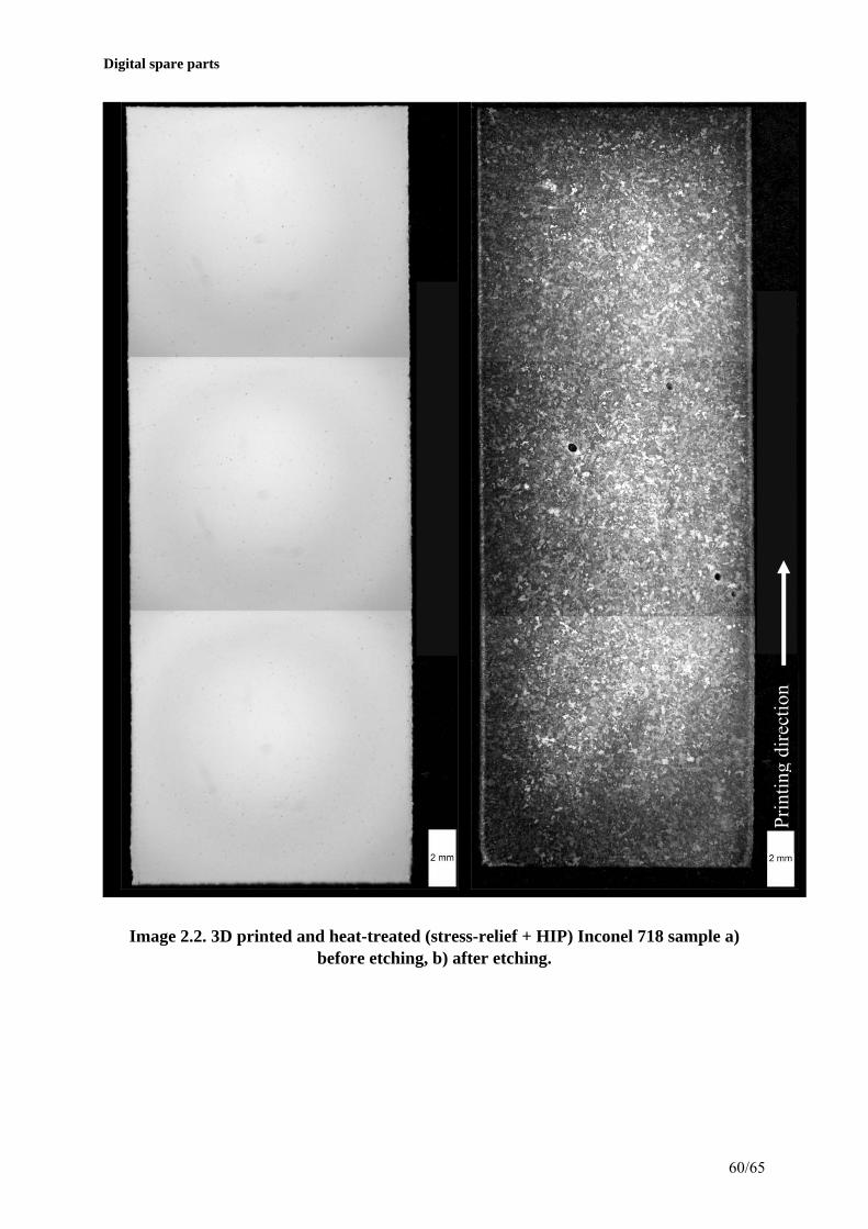
Digital spare parts
60/65
Image 2.2. 3D printed and heat-treated (stress-relief + HIP) Inconel 718 sample a) before etching, b) after etching.
Pri
ntin
g di
rect
ion

Digital spare parts
61/65
Image 2.3. 3D printed and heat-treated (stress-relief + HIP + solvent annealing + precipitation hardening) Inconel 718 sample a) before etching, b) after etching.
Pri
ntin
g di
rect
ion

Digital spare parts
62/65
Appendix 3. Inconel 718 SEM images.
Image 3.1. Inconel 718 in as-built condition SEM image at 2500x magnification.
Image 3.2. Inconel 718 in as-built condition SEM image at 25000x magnification.

Digital spare parts
63/65
Image 3.3. 3D printed and heat-treated (stress-relief + HIP) Inconel 718 SEM image at 2500x magnification.
Image 3.4. 3D printed and heat-treated (stress-relief + HIP) Inconel 718 SEM image at 25000x magnification.
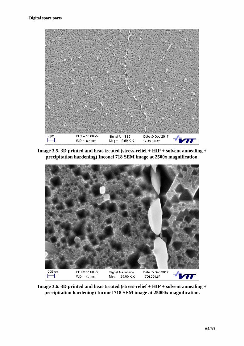
Digital spare parts
64/65
Image 3.5. 3D printed and heat-treated (stress-relief + HIP + solvent annealing + precipitation hardening) Inconel 718 SEM image at 2500x magnification.
Image 3.6. 3D printed and heat-treated (stress-relief + HIP + solvent annealing + precipitation hardening) Inconel 718 SEM image at 25000x magnification.

Digital spare parts
65/65
Appendix 4. Publications of Digital spare parts project. Chekurov, S., Metsä-Kortelainen, S., Salmi, M., Roda I., Jussila, A. The value of digital spare parts in the industry: an empirical investigation. In review.
Chekurov, S., Salmi, M. 2017. Additive Manufacturing in Offsite Repair of Consumer Electronics. Physics Procedia, 89:23–30.
Chekurov, S., Kretzschmar N., Rossani, M., Felice, D., Colombo, G. Axiomatic design of an additively manufactured non-assembly pump. Under preparation
Chekurov, S., Lantela, T. 2017. Selective laser melted digital hydraulic system. 3D printing and additive manufacturing, 4(4).
Jussila, A., Mikkola, M., Tanner, H. 2017. 3D printed spare parts: rethinking supply chains and business models. In Proceedings of the ISPIM Innovation Summit: Building the Innovation Century, Melbourne, Australia, 10-13 December 2017.
Kretzschmar, N., Chekurov, S., Salmi, M., Tuomi, J. Evaluating the Readiness Level of Additively Manufactured Digital Spare Parts. In review.
Reijonen, Joni. 2017. Identifying 3D-printable Spare Parts for a Digitalized Supply Chain. Proceedings. Tampere University of Technology, ss. 37–40. The 2nd Annual SMACC Research Seminar 2017, 7 November 2017, Tampere, Finland.
Vuorela, P. 2017. Spare parts applications of additively manufactured elastic sealing elements. Master thesis, Aalto University.