digital signal processing -...
TRANSCRIPT

Department of Information Technology CS2403-Digital Signal Processing
CS2403 -DIGITAL SIGNAL PROCESSING
UNIT-I
SIGNALS & SYSTEMS 1. Define Signal.
A Signal is defined as any physical quantity that varies with time, space or any
other independent variables.
2. Define a system.
A System is a physical device (i.e., hardware) or algorithm (i.e., software) that
performs an operation on the signal.
3. What are the steps involved in digital signal processing?
Converting the analog signal to digital signal, this is performed by A/D
converter
Processing Digital signal by digital system.
Converting the digital signal to analog signal, this is performed by D/A
converter.
4. Give some applications of DSP?
Speech processing – Speech compression & decompression for voice storage
system
Communication – Elimination of noise by filtering and echo cancellation.
Bio-Medical – Spectrum analysis of ECG,EEG etc.
5. Write the classifications of DT Signals.
Energy & Power signals
Periodic & Aperiodic signals
Even & Odd signals.
6. What is an Energy and Power signal?
Energy signal:
A finite energy signal is periodic sequence, which has a finite energy but zero
average power.
Power signal:
An Infinite energy signal with finite average power is called a power signal.
7. What is Discrete Time Systems?
The function of discrete time systems is to process a given input sequence to
generate output sequence. In practical discrete time systems, all signals are digital
signals, and operations on such signals also lead to digital signals. Such discrete time
systems are called digital filter.
8. Write the Various classifications of Discrete-Time systems.
Linear & Non linear system
Causal & Non Causal system
Stable & Un stable system
Static & Dynamic systems
Department of Information Technology CS2403-Digital Signal Processing
9. Define Linear system
A system is said to be linear system if it satisfies Super position principle. Let us
consider x1(n) & x2(n) be the two input sequences & y1(n) & y2(n) are the responses
respectively,
T[ax1(n) + bx2(n)] = a y1(n) + by2(n)
10. Define Static & Dynamic systems
When the output of the system depends only upon the present input sample, then it
is called static system, otherwise if the system depends past values of input then it is
called dynamic system
11. Define causal system.
When the output of the system depends only upon the present and past input
sample, then it is called causal system, otherwise if the system depends on future values
of input then it is called non-causal system
12. Define Shift-Invariant system.
If y(n) is the response to an input x(n), then the response to an input
X(n) = x(n-n0) then y(n) = y(n-n0)
When the system satisfies above condition then it is said to shift in variant, otherwise it
is variant.
13. Define impulse and unit step signal.
Impulse signal (n):
The impulse signal is defined as a signal having unit magnitude at n = 0 and zero
for other values of n.
(n) = 1; n = 0
0; n 0
Unit step signal u(n):
The unit step signal is defined as a signal having unit magnitude for all
values of n 0
u(n) = 1; n 0
0; n 0
14. What are FIR and IIR systems?
The impulse response of a system consist of infinite number of samples are called
IIR system & the impulse response of a system consist of finite number of samples are
called FIR system.
15. What are the basic elements used to construct the block diagram of discrete time
system?
The basic elements used to construct the block diagram of discrete time
Systems are Adder, Constant multiplier &Unit delay element.
16. What is ROC in Z-Transform?
The values of z for which z – transform converges is called region of convergence
(ROC). The z-transform has an infinite power series; hence it is necessary to mention
the ROC along with z-transform.
17. List any four properties of Z-Transform.
Linearity

Department of Information Technology CS2403-Digital Signal Processing
Time Shifting
Frequency shift or Frequency translation
Time reversal
18. What are the different methods of evaluating inverse z-transform?
Partial fraction expansion
Power series expansion
Contour integration (Residue method)
19. Define sampling theorem.
A continuous time signal can be represented in its samples and recovered back if
the sampling frequency Fs 2B. Here ‘Fs’ is the sampling frequency and ‘B’ is the
maximum frequency present in the signal.
20. Check the linearity and stability of g(n),
Since square root is nonlinear, the system is nonlinear.
As long as x(n) is bounded, its square root is bounded. Hence this system is
stable.
21. What are the properties of convolution?
1. Commutative property x(n) * h(n) = h(n) * x(n)
2. Associative property [x(n) * h1(n)]*h2(n) = x(n)*[h1(n) * h2(n)]
3. Distributive property x(n) *[ h1(n)+h2(n)] = [x(n)*h1(n)]+[x(n) * h2(n)]
UNIT-II
DISCRETE TIME SYSTEM ANALYSIS
1. Define DTFT.
Let us consider the discrete time signal x(n).Its DTFT is denoted as X(w).It is given as
X(w)= x(n)e-jwn
2. State the condition for existence of DTFT?
The conditions are
• If x(n)is absolutely summable then
|x(n)|<
• If x(n) is not absolutely summable then it should have finite energy for
DTFT to exit.
3. List the properties of DTFT.
Periodicity
Linearity
Time shift
Frequency shift
Scaling
Differentiation in frequency domain
Time reversal
Convolution
Multiplication in time domain
Parseval’s theorem
Department of Information Technology CS2403-Digital Signal Processing
4. What is the DTFT of unit sample?
The DTFT of unit sample is 1 for all values of w.
5. Define DFT.
DFT is defined as X(w)= x(n)e-jwn.
Here x(n) is the discrete time sequence
X(w) is the fourier transform ofx(n).
6. Define Twiddle factor.
The Twiddle factor is defined as WN=e-j2 /N
7. Define Zero padding.
The method of appending zero in the given sequence is called as Zero padding.
8. Define circularly even sequence.
A Sequence is said to be circularly even if it is symmetric about the point zero on
the circle. x(N-n)=x(n),1<=n<=N-1.
9. Define circularly odd sequence.
A Sequence is said to be circularly odd if it is anti symmetric about point x(0) on the circle
10. Define circularly folded sequences.
A circularly folded sequence is represented as x((-n))N. It is obtained by plotting x(n) in
clockwise direction along the circle.
11. State circular convolution.
This property states that multiplication of two DFT is equal to circular convolution of their
sequence in time domain.
12. State parseval’s theorem.
Consider the complex valued sequences x(n) and y(n).If
x(n)y*(n)=1/N X(k)Y*(k)
13. Define Z transform.
The Z transform of a discrete time signal x(n) is denoted by X(z) and is given
by X(z)= x(n)Z-n.
14. Define ROC.
The value of Z for which the Z transform converged is called region of convergence.
15. Find Z transform of x(n)={1,2,3,4}
x(n)= {1,2,3,4}
X(z)= x(n)z-n
= 1+2z-1
+3z-2
+4z-3.
= 1+2/z+3/z2+4/z
3.
16. State the convolution property of Z transform.
The convolution property states that the convolution of two sequences in time domain is
equivalent to multiplication of their Z transforms.
17. What z transform of (n-m)?
By time shifting property
Z[A (n-m)]=AZ-m
sin Z[ (n)] =1
Department of Information Technology CS2403-Digital Signal Processing
18. State initial value theorem.
If x(n) is causal sequence then its initial value is given by x(0)=lim X(z)
19. List the methods of obtaining inverse Z transform.
Inverse z transform can be obtained by using
Partial fraction expansion.
Contour integration
Power series expansion
Convolution.
20. Obtain the inverse z transform of X(z)=1/z-a,|z|>|a|
Given X(z)=z-1/1-az-1
By time shifting property
X(n)=an.u(n-1)
UNIT-III DISCRETE FOURIER TRANSFORM AND COMPUTATION
1. What is DFT?
It is a finite duration discrete frequency sequence, which is obtained by sampling one
period of Fourier transform. Sampling is done at N equally spaced points over the
period extending from w=0 to 2л.
2. Define N point DFT.
The DFT of discrete sequence x(n) is denoted by X(K). It is given by,
Here k=0,1,2…N-1
Since this summation is taken for N points, it is called as N-point DFT.
3. What is DFT of unit impulse δ(n)?
The DFT of unit impulse δ(n) is unity.
4. List the properties of DFT.
Linearity, Periodicity, Circular symmetry, symmetry, Time shift, Frequency shift,
complex conjugate, convolution, correlation and Parseval’s theorem.
5. State Linearity property of DFT.
DFT of linear combination of two or more signals is equal to the sum of linear
combination of DFT of individual signal.
6. When a sequence is called circularly even?
The N point discrete time sequence is circularly even if it is symmetric about the point
zero on the circle.
7. What is the condition of a sequence to be circularly odd?
An N point sequence is called circularly odd it if is antisymmetric about point zero on
the circle.
8. Why the result of circular and linear convolution is not same?
Circular convolution contains same number of samples as that of x (n) and h (n), while
in linear convolution, number of samples in the result (N) are,

Department of Information Technology CS2403-Digital Signal Processing
N=L+M-1
Where L= Number of samples in x (n)
M=Number of samples in h (n)
9. What is circular time shift of sequence?
Shifting the sequence in time domain by ‘1’ samples is equivalent to multiplying the
sequence in frequency domain by WNkl
10. What is the disadvantage of direct computation of DFT?
For the computation of N-point DFT, N2 complex multiplications and N[N-1] Complex
additions are required. If the value of N is large than the number of computations will
go into lakhs. This proves inefficiency of direct DFT computation.
11. What is the way to reduce number of arithmetic operations during DFT
computation?
Number of arithmetic operations involved in the computation of DFT is greatly reduced
by using different FFT algorithms as follows.
1. Radix-2 FFT algorithms.
-Radix-2 Decimation in Time (DIT) algorithm.
- Radix-2 Decimation in Frequency (DIF) algorithm.
2. Radix-4 FFT algorithm.
12. What is the computational complexity using FFT algorithm?
1. Complex multiplications = N/2 log2N
2. Complex additions = N log2N
13. How linear filtering is done using FFT?
Correlation is the basic process of doing linear filtering using FFT. The correlation is
nothing but the convolution with one of the sequence, folded. Thus, by folding the
sequence h (n), we can compute the linear filtering using FFT.
14. What is zero padding? What are its uses?
Let the sequence x (n) has a length L. If we want to find the N point DFT (N>L) of the
sequence x (n). This is known as zero padding. The uses of padding a sequence with
zeros are
(i) We can get ‘better display’ of the frequency spectrum.
(ii) With zero padding, the DFT can be used in linear filtering.
15. Why FFT is needed?
The direct evaluation of the DFT using the formula requires N2
complex multiplications
and N (N-1) complex additions. Thus for reasonably large values of N (inorder of 1000)
direct evaluation of the DFT requires an inordinate amount of computation. By using
FFT algorithms the number of computations can be reduced. For example, for an N-
point DFT, The number of complex multiplications required using FFT is N/2log2N. If
N=16, the number of complex multiplications required for direct evaluation of DFT is
256, whereas using DFT only 32 multiplications are required.
16. What is the speed of improvement factor in calculating 64-point DFT of a sequence
using direct computation and computation and FFT algorithms?
Or
Calculate the number of multiplications needed in the calculation of DFT and FFT
with 64-point sequence.

Department of Information Technology CS2403-Digital Signal Processing
The number of complex multiplications required using direct computation is
N2=642=4096.
The number of complex multiplications required using FFT is
N/2 log2N = 64/2log264=192.
Speed improvement factor = 4096/192=21.33
17. What is the main advantage of FFT?
FFT reduces the computation time required to compute discrete Fourier transform.
18. Calculate the number of multiplications needed in the calculation of DFT using
FFT algorithm with using FFT algorithm with 32-point sequence.
For N-point DFT the number of complex multiplications needed using FFT algorithm is
N/2 log2N.
For N=32, the number of the complex multiplications is equal to 32/2log232=16*5=80.
19. What is FFT?
The fast Fourier transforms (FFT) is an algorithm used to compute the DFT. It makes
use of the Symmetry and periodically properties of twiddles factor WK
N
to effectively reduce the DFT computation time. It is based on the fundamental
principle of decomposing the computation of the DFT of a sequence of length N into
successively smaller discrete Fourier transforms. The FFT algorithm provides speed-
increase factors, when compared with direct computation of the DFT, of approximately
64 and 205 for 256-point and 1024-point transforms, respectively.
20. How many multiplications and additions are required to compute N-point DFT
using redix-2 FFT?
The number of multiplications and additions required to compute N-point DFT using
redix-2 FFT are N log2N and N/2 log2N respectively.
21. What is meant by radix-2 FFT?
The FFT algorithm is most efficient in calculating N-point DFT. If the number of
output points N can be expressed as a power of 2, that is, N=2M
, where M is an integer,
Then this algorithm is known as radix-s FFT algorithm.
22. What is a decimation-in-time algorithm?
Decimation-in-time algorithm is used to calculate the DFT of a N-point Sequence. The
idea is to break the N-point sequence into two sequences, the DFTs of which can be
combined to give the DFT of the original N-point sequence. Initially the N-point
sequence is divided into two N/2-point sequences xe(n) and x0(n), which have the even
and odd members of x(n) respectively. The N/2 point DFTs of these two sequences are
evaluated and combined to give the N point DFT. Similarly the N/2 point DFTs can be
expressed as a combination of N/4 point DFTs. This process is continued till we left
with 2-point DFT. This algorithm is called Decimation-in-time because the sequence
x(n) is often splitted into smaller sub sequences.
23. What are the differences and similarities between DIF and DIT algorithms?
Differences:
1. For DIT, the input is bit reversal while the output is in natural order, whereas for
DIF, the input is in natural order while the output is bit reversed.
2. The DIF butterfly is slightly different from the DIT butterfly, the difference being
that the complex multiplication takes place after the add-subtract operation in DIF.
Similarities: Both algorithms require same number of operations to compute the DFT.
Both
Department of Information Technology CS2403-Digital Signal Processing
algorithms can be done in place and both need to perform bit reversal at some place
during the computation.
24. What are the applications of FFT algorithms?
1. Linear filtering
2. Correlation
3. Spectrum analysis
25. What is a decimation-in-frequency algorithm?
In this the output sequence X (K) is divided into two N/2 point sequences and each N/2
point sequences are in turn divided into two N/4 point sequences.
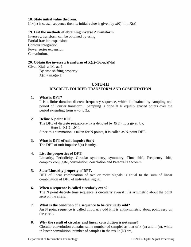
26. Distinguish between DFT and DTFT.
S.No DFT DTFT
1.
2.
Obtained by performing sampling
operation in both the time and
frequency domains.
Discrete frequency spectrum
Sampling is performed only in
time domain.
Continuous function of ω
27. Distinguish between Fourier series and Fourier transform.
S.No. Fourier Series Fourier transform
1
2.
Gives the harmonic content of a
periodic time function.
Discrete frequency spectrum
Gives the frequency information
for an aperiodic signal.
Continuous frequency spectrum
UNIT-IV
DESIGN OF DEGITAL FILTER 1) Define IIR filter?
IIR filter has Infinite Impulse Response.
2) What are the various methods to design IIR filters?
Approximation of derivatives
Impulse invariance
Bilinear transformation.
3) Which of the methods do you prefer for designing IIR filters? Why?
Bilinear transformation is best method to design IIR filter, since there is no aliasing
in it.
4) What is the main problem of bilinear transformation?
Frequency warping or nonlinear relationship is the main problem of bilinear
transformation.
5) What is prewarping?
Prewarping is the method of introducing nonlinearly in frequency relationship to
compensate warping effect.
Department of Information Technology CS2403-Digital Signal Processing
6) State the frequency relationship in bilinear transformation?
= 2 tan (w/2)
T
7) Where the j axis of s-plane is mapped in z-plane in bilinear transformation?
The j axis of s-plane is mapped on the unit circle in z-plane in bilinear
transformation
8) Where left hand side and right hand side are mapped in z-plane in bilinear
transformation?
Left hand side -- Inside unit circle
Right hand side – Outside unit circle
9) What is the frequency response of Butterworth filter?
Butterworth filter has monotonically reducing frequency response.
10) Which filter approximation has ripples in its response?
Chebyshev approximation has ripples in its pass band or stop band.
11) Can IIR filter be designed without analog filters?
Yes. IIR filter can be designed using pole-zero plot without analog filters
12) What is the advantage of designing IIR Filters using pole-zero plots?
The frequency response can be located exactly with the help of poles and zeros.
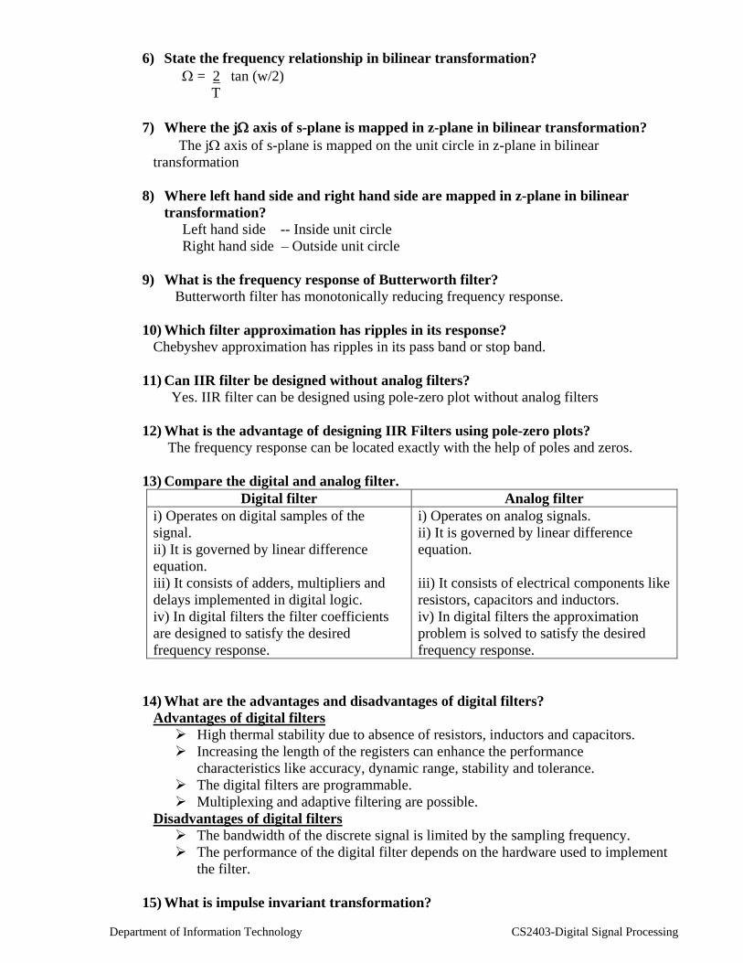
13) Compare the digital and analog filter.
Digital filter Analog filter
i) Operates on digital samples of the
signal.
ii) It is governed by linear difference
equation.
iii) It consists of adders, multipliers and
delays implemented in digital logic.
iv) In digital filters the filter coefficients
are designed to satisfy the desired
frequency response.
i) Operates on analog signals.
ii) It is governed by linear difference
equation.
iii) It consists of electrical components like
resistors, capacitors and inductors.
iv) In digital filters the approximation
problem is solved to satisfy the desired
frequency response.
14) What are the advantages and disadvantages of digital filters?
Advantages of digital filters
High thermal stability due to absence of resistors, inductors and capacitors.
Increasing the length of the registers can enhance the performance
characteristics like accuracy, dynamic range, stability and tolerance.
The digital filters are programmable.
Multiplexing and adaptive filtering are possible.
Disadvantages of digital filters
The bandwidth of the discrete signal is limited by the sampling frequency.
The performance of the digital filter depends on the hardware used to implement
the filter.
15) What is impulse invariant transformation?

Department of Information Technology CS2403-Digital Signal Processing
The transformation of analog filter to digital filter without modifying the impulse
response of the filter is called impulse invariant transformation.
16) Obtain the impulse response of digital filter to correspond to an analog filter with
impulse response ha(t) = 0.5 e-2t
and with a sampling rate of 1.0kHz using impulse
invariant method.
17) How analog poles are mapped to digital poles in impulse invariant
transformation?
In impulse invariant transformation the mapping of analog to digital poles are as
follows,
The analog poles on the left half of s-plane are mapped into the interior of unit
circle in z-plane.
The analog poles on the imaginary axis of s-plane are mapped into the unit circle
in the z-plane.
The analog poles on the right half of s-plane are mapped into the exterior of unit
circle in z-plane.
18) What is the importance of poles in filter design?
The stability of a filter is related to the location of the poles. For a stable analog filter
the poles should lie on the left half of s-plane. For a stable digital filter the poles should
lie inside the unit circle in the z-plane.
19) Why an impulse invariant transformation is not considered to be one-to-one?
In impulse invariant transformation any strip of width 2π/T in the s-plane for values
of s-plane in the range (2k-1)/T Ω (2k-1) π/T is mapped into the entire z-plane.
The left half of each strip in s-plane is mapped into the interior of unit circle in z-
plane, right half of each strip in s-plane is mapped into the exterior of unit circle in
z-plane and the imaginary axis of each strip in s-plane is mapped on the unit circle
in z-plane. Hence the impulse invariant transformation is many-to-one.
20) What is Bilinear transformation?
The bilinear transformation is conformal mapping that transforms the s-plane to z-
plane. In this mapping the imaginary axis of s-plane is mapped into the unit circle in z-
plane, The left half of s-plane is mapped into interior of unit circle in z-plane and the
right half of s-plane is mapped into exterior of unit circle in z-plane. The Bilinear
mapping is a one-to-one mapping and it is accomplished when
21) How the order of the filter affects the frequency response of Butterworth filter.
The magnitude response of butterworth filter is shown in figure, from which it can
be observed that the magnitude response approaches the ideal response as the order of
the filter is increased.
22) Write the properties of Chebyshev type –1 filters.
The magnitude response is equiripple in the passband and monotonic in the
stopband.
The chebyshev type-1 filters are all pole designs.
The normalized magnitude function has a value of at the cutoff
frequency c.
The magnitude response approaches the ideal response as the value of N
increases.
Department of Information Technology CS2403-Digital Signal Processing
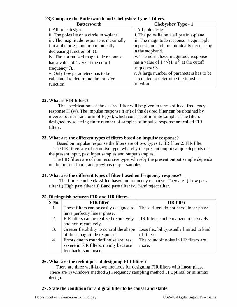
23) Compare the Butterworth and Chebyshev Type-1 filters.
Butterworth Chebyshev Type - 1
i. All pole design.
ii. The poles lie on a circle in s-plane.
iii. The magnitude response is maximally
flat at the origin and monotonically
decreasing function of .
iv. The normalized magnitude response
has a value of 1 / 2 at the cutoff
frequency c.
v. Only few parameters has to be
calculated to determine the transfer
function.
i. All pole design.
ii. The poles lie on a ellipse in s-plane.
iii. The magnitude response is equiripple
in passband and monotonically decreasing
in the stopband.
iv. The normalized magnitude response
has a value of 1 / (1+2) at the cutoff
frequency c.
v. A large number of parameters has to be
calculated to determine the transfer
function.
22. What is FIR filters?
The specifications of the desired filter will be given in terms of ideal frequency
response Hd(w). The impulse response hd(n) of the desired filter can be obtained by
inverse fourier transform of Hd(w), which consists of infinite samples. The filters
designed by selecting finite number of samples of impulse response are called FIR
filters.
23. What are the different types of filters based on impulse response?
Based on impulse response the filters are of two types 1. IIR filter 2. FIR filter
The IIR filters are of recursive type, whereby the present output sample depends on
the present input, past input samples and output samples.
The FIR filters are of non recursive type, whereby the present output sample depends
on the present input, and previous output samples.
24. What are the different types of filter based on frequency response?
The filters can be classified based on frequency response. They are I) Low pass
filter ii) High pass filter iii) Band pass filter iv) Band reject filter.
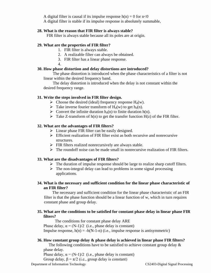
25. Distinguish between FIR and IIR filters.
S.No. FIR filter IIR filter
1.
2.
3.
4.
These filters can be easily designed to
have perfectly linear phase.
FIR filters can be realized recursively
and non-recursively.
Greater flexibility to control the shape
of their magnitude response.
Errors due to roundoff noise are less
severe in FIR filters, mainly because
feedback is not used.
These filters do not have linear phase.
IIR filters can be realized recursively.
Less flexibility,usually limited to kind
of filters.
The roundoff noise in IIR filters are
more.
26. What are the techniques of designing FIR filters?
There are three well-known methods for designing FIR filters with linear phase.
These are 1) windows method 2) Frequency sampling method 3) Optimal or minimax
design.
27. State the condition for a digital filter to be causal and stable.
Department of Information Technology CS2403-Digital Signal Processing
A digital filter is causal if its impulse response h(n) = 0 for n<0
A digital filter is stable if its impulse response is absolutely summable,
28. What is the reason that FIR filter is always stable?
FIR filter is always stable because all its poles are at origin.
29. What are the properties of FIR filter?
1. FIR filter is always stable.
2. A realizable filter can always be obtained.
3. FIR filter has a linear phase response.
4.
30. How phase distortion and delay distortions are introduced?
The phase distortion is introduced when the phase characteristics of a filter is not
linear within the desired frequency band.
The delay distortion is introduced when the delay is not constant within the
desired frequency range.
31. Write the steps involved in FIR filter design.
Choose the desired (ideal) frequency response Hd(w).
Take inverse fourier transform of Hd(w) to get hd(n).
Convert the infinite duration hd(n) to finite duration h(n).
Take Z-transform of h(n) to get the transfer function H(z) of the FIR filter.
32. What are the advantages of FIR filters?
Linear phase FIR filter can be easily designed.
Efficient realization of FIR filter exist as both recursive and nonrecursive
structures.
FIR filters realized nonrecursively are always stable.
The roundoff noise can be made small in nonrecursive realization of FIR filters.
33. What are the disadvantages of FIR filters?
The duration of impulse response should be large to realize sharp cutoff filters.
The non-integral delay can lead to problems in some signal processing
applications.
34. What is the necessary and sufficient condition for the linear phase characteristic of
an FIR filter?
The necessary and sufficient condition for the linear phase characteristic of an FIR
filter is that the phase function should be a linear function of w, which in turn requires
constant phase and group delay.
35. What are the conditions to be satisfied for constant phase delay in linear phase FIR
filters?
The conditions for constant phase delay ARE
Phase delay, α = (N-1)/2 (i.e., phase delay is constant)
Impulse response, h(n) = -h(N-1-n) (i.e., impulse response is antisymmetric)
36. How constant group delay & phase delay is achieved in linear phase FIR filters?
The following conditions have to be satisfied to achieve constant group delay &
phase delay.
Phase delay, α = (N-1)/2 (i.e., phase delay is constant)
Group delay, β = π/2 (i.e., group delay is constant)
Department of Information Technology CS2403-Digital Signal Processing
Impulse response, h(n) = -h(N-1-n) (i.e., impulse response is antisymmetric)
37. What are the possible types of impulse response for linear phase FIR filters?
There are four types of impulse response for linear phase FIR filters
Symmetric impulse response when N is odd.
Symmetric impulse response when N is even.
Antisymmetric impulse response when N is odd.
Antisymmetric impulse response when N is even.
38. List the well-known design techniques of linear phase FIR filters.
There are three well-known design techniques of linear phase FIR filters. They are
Fourier series method and window method
Frequency sampling method.
Optimal filter design methods.
39. What is Gibb’s phenomenon (or Gibb’s Oscillation)?
In FIR filter design by Fourier series method the infinite duration impulse
response is truncated to finite duration impulse response. The abrupt truncation of
impulse response introduces oscillations in the passband and stopband. This effect is
known as Gibb’s phenomenon (or Gibb’s Oscillation).
40. When cascade form realization is preferred in FIR filters?
The cascade form realization is preferred when complex zeros with absolute
magnitude less than one.
41. What are the desirable characteristics of the frequency response of window
function?
The desirable characteristics of the frequency response of window function are
The width of the mainlobe should be small and it should contain as much of the
total energy as possible.
The sidelobes should decrease in energy rapidly as w tends to π.
42. Write the procedure for designing FIR filter using frequency-sampling method.
Choose the desired (ideal) frequency response Hd(w).
Take N-samples of Hd(w) to generate the sequence
Take inverse DFT of to get the impulse response h(n).
The transfer function H(z) of the filter is obtained by taking z-transform of
impulse response.
43. What are the drawback in FIR filter design using windows and frequency
sampling method? How it is overcome?
The FIR filter design using windows and frequency sampling method does not have
Precise control over the critical frequencies such as wp and ws.
This drawback can be overcome by designing FIR filter using Chebyshev
approximation technique.In this technique an error function is used to approximate the
ideal frequency response, in order to satisfy the desired specifications.
44. Write the characteristic features of rectangular window.
The mainlobe width is equal to 4π/N.
The maximum sidelobe magnitude is –13dB.
The sidelobe magnitude does not decrease significantly with increasing w.
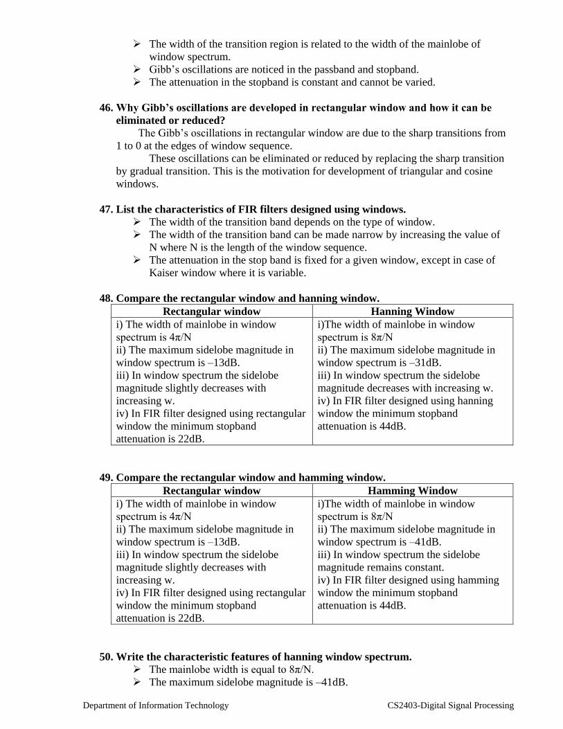
45. List the features of FIR filter designed using rectangular window.
Department of Information Technology CS2403-Digital Signal Processing
The width of the transition region is related to the width of the mainlobe of
window spectrum.
Gibb’s oscillations are noticed in the passband and stopband.
The attenuation in the stopband is constant and cannot be varied.
46. Why Gibb’s oscillations are developed in rectangular window and how it can be
eliminated or reduced?
The Gibb’s oscillations in rectangular window are due to the sharp transitions from
1 to 0 at the edges of window sequence.
These oscillations can be eliminated or reduced by replacing the sharp transition
by gradual transition. This is the motivation for development of triangular and cosine
windows.
47. List the characteristics of FIR filters designed using windows.
The width of the transition band depends on the type of window.
The width of the transition band can be made narrow by increasing the value of
N where N is the length of the window sequence.
The attenuation in the stop band is fixed for a given window, except in case of
Kaiser window where it is variable.
48. Compare the rectangular window and hanning window.
Rectangular window Hanning Window
i) The width of mainlobe in window
spectrum is 4π/N
ii) The maximum sidelobe magnitude in
window spectrum is –13dB.
iii) In window spectrum the sidelobe
magnitude slightly decreases with
increasing w.
iv) In FIR filter designed using rectangular
window the minimum stopband
attenuation is 22dB.
i)The width of mainlobe in window
spectrum is 8π/N
ii) The maximum sidelobe magnitude in
window spectrum is –31dB.
iii) In window spectrum the sidelobe
magnitude decreases with increasing w.
iv) In FIR filter designed using hanning
window the minimum stopband
attenuation is 44dB.
49. Compare the rectangular window and hamming window.
Rectangular window Hamming Window
i) The width of mainlobe in window
spectrum is 4π/N
ii) The maximum sidelobe magnitude in
window spectrum is –13dB.
iii) In window spectrum the sidelobe
magnitude slightly decreases with
increasing w.
iv) In FIR filter designed using rectangular
window the minimum stopband
attenuation is 22dB.
i)The width of mainlobe in window
spectrum is 8π/N
ii) The maximum sidelobe magnitude in
window spectrum is –41dB.
iii) In window spectrum the sidelobe
magnitude remains constant.
iv) In FIR filter designed using hamming
window the minimum stopband
attenuation is 44dB.
50. Write the characteristic features of hanning window spectrum.
The mainlobe width is equal to 8π/N.
The maximum sidelobe magnitude is –41dB.

Department of Information Technology CS2403-Digital Signal Processing
The sidelobe magnitude remains constant for increasing w.
51. What is the mathematical problem involved in the design of window function?
The mathematical problem involved in the design of window function(or
sequence) is that of finding a time-limited function whose Fourier Transform best
approximates a band limited function. The approximation should be such that the
maximum energy is confined to mainlobe for a given peak sidelobe amplitude.
52. List the desirable features of Kaiser Window spectrum.
The width of the mainlobe and the peak sidelobe are variable.
The parameter α in the Kaiser Window function is an independent variable that
can be varied to control the sidelobe levels with respect to mainlobe peak.
The width of the mainlobe in the window spectrum can be varied by varying the
length N of the window sequence.
53. Compare the hamming window and Kaiser window.
Hamming Window Kaiser Window
i)The width of mainlobe in window
spectrum is 8π/N
ii) The maximum sidelobe magnitude in
window spectrum is –41dB.
iii) In window spectrum the sidelobe
magnitude remains constant.
iv) In FIR filter designed using hamming
window the minimum stopband
attenuation is 44dB.
i) The width of mainlobe in window
spectrum depends on the values of α & N.
ii) The maximum sidelobe magnitude with
respect to peak of mainlobe is variable
using the parameter α.
iii) In window spectrum the sidelobe
magnitude decreases with increasing w.
iv) In FIR filter designed using Kaiser
window the minimum stopband
attenuation is variable and depends on the
value of α.
UNIT V
1. Write short notes on general purpose DSP processors
General-purpose digital signal processors are basically high speed microprocessors
with hard ware architecture and instruction set optimized for DSP operations. These
processors make extensive use of parallelism, Harvard architecture, pipelining and
dedicated hardware whenever possible to perform time consuming operations
.
2. Write notes on special purpose DSP processors.
There are two types of special; purpose hardware.
(i) Hardware designed for efficient execution of specific DSP algorithms such
as digital filter, FFT.
(ii) Hardware designed for specific applications, for example
telecommunication, digital audio.
3. Briefly explain about Harvard architecture.
The principal feature of Harvard architecture is that the program and the data
memories lie in two separate spaces, permitting full overlap of instruction fetch and
execution.
Typically these types of instructions would involve their distinct type.
1. Instruction fetch
2. Instruction decode

Department of Information Technology CS2403-Digital Signal Processing
3. Instruction execute
4. Briefly explain about multiplier accumulator.
The way to implement the correlation and convolution is array multiplication
Method.
For getting down these operations we need the help of adders and multipliers. The
combination of these accumulator and multiplier is called as multiplier accumulator.
5. What are the types of MAC is available?
There are two types MAC’S available
1. Dedicated & integrated
2. Separate multiplier and integrated unit
6. What is meant by pipeline technique?
The pipeline technique is used to allow overall instruction executions to overlap.
That is where all four phases operate in parallel. By adapting this technique,
execution speed is increased.
7. What are four phases available in pipeline technique?
The four phases are
(i) Fetch
(ii) Decode
(iii) Read
(iv) Execution
8. In a non-pipeline machine, the instruction fetch, decode and execute take 30
ns, 45 ns and 25 ns respectively. Determine the increase in throughput if the
instruction were pipelined. Assume a 5ns pipeline overhead in each stage and ignore
other delays.
The average instruction time is = 30 ns+45 ns + 25 ns = 100 ns
Each instruction has been completed in three cycles = 45 ns * 3 = 135ns
Throughput of the machine =
The average instruction time/Number of M/C per instruction
= 100/135 = 0.7407
But in the case of pipeline machine, the clock speed is determined by the speed of the
slowest stage plus overheads.
In our case is = 45 ns + 5 ns =50 ns
The respective throughput is = 100/50 = 2.00
The amount of speed up the operation is = 135/50 = 2.7 times
9.Assume a memory access time of 150 ns, multiplication time of 100 ns, addition
time of 100 ns and overhead of 10 ns at each pipe stage. Determine the throughput
of MAC
After getting successive addition and multiplications
The total time delay is 150 + 100 + 100 + 5 = 355 ns
System throughput is = 1/355 ns.
10.Write down the name of the addressing modes.
Direct addressing.
Indirect addressing.
Bit-reversed addressing.
Immediate addressing.
i. Short immediate addressing.

Department of Information Technology CS2403-Digital Signal Processing
ii. Long immediate addressing.
Circular addressing.
11.What are the instructions used for block transfer in C5X Processors?
The BLDD, BLDP and BLPD instructions use the BMAR to point at the
source or destination space of a block move. The MADD and MADS also use
the BMAR to address an operand in program memory for a multiply
accumulator operation
12.Briefly explain about the dedicated register addressing modes.
The dedicated-registered addressing mode operates like the long
immediate addressing modes, except that the address comes from one of two
special-purpose memory-mapped registers in the CPU: the block move address
register (BMAR) and the dynamic bit manipulation register (DBMR).
The advantage of this addressing mode is that the address of the block of
memory to be acted upon can be changed during execution of the program.
13. Briefly explain about bit-reversed addressing mode?
In the bit-reversed addressing mode, INDX specifies one-half the size of the
FFT. The value contained in the current AR must be equal to 2n-1, where n is
an integer, and the FFT size is 2n. An auxiliary register points to the physical
location of a data value. When we add INDX t the current AR using bit reversed
addressing, addresses are generated in a bit-reversed fashion. Assume that the
auxiliary registers are eight bits long, that AR2 represents the base address of the
data in memory (0110 00002), and that INDX contains the value 0000 10002.
14. Briefly explain about circular addressing mode.
Many algorithms such as convolution, correlation, and finite impulse response
(FIR) filters can use circular buffers in memory to implement a sliding window;
which contains the most recent data to be processed. The ‘C5x supports two
concurrent circular buffer operating via the ARs. The following five memory-
mapped registers control the circular buffer operation.
1. CBSR1- Circular buffer 1 start register.
2. CBSR2- Circular buffer 2 start Register,
3. CBER1- Circular buffer 1 end register
4. CBER2- Circular buffer 2 end register
5. CBCR - Circular buffer control register.
15. Write the name of various part of C5X hardware.
1. Central arithmetic logic unit (CALU)
2. Parallel logic unit (PLU)
3. Auxiliary register arithmetic unit (ARAU)
4. Memory-mapped registers.
5. Program controller.
16. Write short notes about arithmetic logic unit and accumulator.
The 32-bit general-purpose ALU and ACC implement a wide range of arithmetic
and logical functions, the majority of which execute in a single clock cycle.
Once an operation is performed in the ALU, the result is transferred to the ACC,
where additional operations, such as shifting, can occur. Data that is input to the
ALU can be scaled by the prescaler.
The following steps occur in the implementation of a typical ALU instruction:
Department of Information Technology CS2403-Digital Signal Processing
1. Data is fetched from memory on the data bus,
2. Data is passed through the prescaler and the ALU, where the arithmetic
is performed, and
3. The result is moved into the ACC.
The ALU operates on 16-bit words taken from data memory or derived from
immediate instructions. In addition to the usual arithmetic instructions, the ALU
can perform Boolean operations, thereby facilitating the bit manipulation ability
required of high-speed controller. One input to the ALU is always supplied by
the ACC. The other input can be transferred from the PREG of the multiplier,
the ACCB, or the output of the prescaler. After the ALU has performed the
arithmetic or logical operation, the result is stored in the ACC.
17. Write short notes about parallel logic unit.
The parallel logic unit (PLU) can directly set, clear, test, or toggle multiple bits
in control/status register pr any data memory location. The PLU provides a
direct logic operation path to data memory values without affecting the contents
of the ACC or the PREG.
18. What is meant by auxiliary register file?
The auxiliary register file contains eight memory-mapped auxiliary registers
(AR0-AR7), which can be used for indirect addressing of the data memory or for
temporary data storage. Indirect auxiliary register addressing allows placement
of the data memory address of an instruction operand into one of the AR. The
ARs are pointed to by a 3-bit auxiliary register pointer (ARP) that is loaded with
a value from 0-7, designating AR0-AR7, respectively.
19. Write short notes about circular registers in C5X.
The ‘C5x devices support two concurrent circular buffers operating in
conjunction with user-specified auxiliary register. Two 16-bit circular buffer
start registers (CBSR1 and CBSR2) indicate the address where the circular
buffer starts. Two 16-bit circular buffer end registers (CBER1 and CBER2)
indicate the address where the circular buffer ends. The 16-bit circular buffer
control register (CBCR) controls the operation of these circular buffers and
identifies the auxiliary registers to be used.