digital servoproportional 3-way cartridges - atos · atos digital proportionals valves are ce...
TRANSCRIPT

FS340
Table FS340-4/E
LIQZO-LEB, LIQZP-LEB LIQZO-LES, LIQZP-LES
Digital servoproportional 3-way cartridges specifically designed for high speed closed loop controls. They are equipped with two LVDT position transducers for best dynamics in directional controls and not compensated flow regulations. The cartridge execution for blocks installation grants high flow capabili-ties and minimized pressure drops. LEB basic execution with analog reference signal and USB port for software functional parameters setting. LES full execution which includes also optional alternated P/Q controls and fieldbus interfaces for functional parameters setting, reference signals and real-time diagnostics.
LIQZO: Size: 25 ÷ 40 Max flow: 500 ÷ 1050 l/min Max pressure: 350 bar
LIQZP: Size: 50 ÷ 80 Max flow: 2000 ÷ 5000 l/min Max pressure: 420 bar
Digital servoproportional 3-way cartridges piloted, with on-board driver and two LVDT transducers
�
�
�
�
�
�
�
�
�
zMain spool
Sleeve
Main stage LVDT transducer
Pilot valve On-board digital driver
USB connector
Fieldbus connectors
Main connector
Pilot valve LVDT transducer
Air bleeding
Air suction port
X Y
T
A
LES
LIQZO-LES-SN-BP-323L4/A
Fieldbus interfaces, USB port always present: NP = Not present BC = CANopen EW = POWERLINK BP = PROFIBUS DP EI = EtherNet/IP EH = EtherCAT EP = PROFINET RT/IRT
LEB = basic on-board digital driver (1) LES = full on-board digital driver
��
Hydraulic options (2): A = reversal hydraulic configuration of main spool:
P-A in rest position
Electronic options (2): C = current feedback for pressure transducer 4÷20mA
(omit for std voltage ±10VDC) - only LES-SP, SL F = fault signal I = current reference input and monitor 4÷20mA
(omit for std voltage ±10VDC) Q = enable signal Z = double power supply, enable, fault and
monitor signals - 12 pin connector (3)
LIQZO / /- 25 3 L4 * * *
Spool type regulating characteristics:
L4 = linear
Configuration: 3 = 3 way
1
Valve size, see section :
LIQZO = 25 32 40 l/min 185 330 420
LIQZP = 50 63 80 l/min 780 1250 2100
Nominal flow (l/min) at Δp 5 bar
7
Servoproportional 3-way cartridge, piloted
LIQZO = size 25 to 40, Pmax 350 bar
LIQZP = size 50 to 80, Pmax 420 bar
Alternated P/Q controls: SN = none SP = pressure control (1 pressure transducer) SL = force control (1 load cell)
-- - NPSN
functional symbol: Standard
simplified symbol: Standard
option /A
option /A
(1) Only in version SN-NP (2) For possible combined options, see section (3) Double power supply only for LES13
P
Series number
Seals material, see section :
- = NBR PE = FKM BT = HNBR
9
MODEL CODE
�
�
�
�
�
�
�
2 GENERAL NOTES
Atos digital proportionals valves are CE marked according to the applicable directives (e.g. Immunity and Emission EMC Directive). Installation, wirings and start-up procedures must be performed according to the general prescriptions shown in tech table FS900 and in the user manuals included in the E-SW-* programming software.
Fieldbus allows valve direct communication with machine control unit for digital reference, valve diagnostics and settings. These execution allow to operate the valves through fieldbus or analog signals available on the main connector.
4 FIELDBUS - only for LES, see tech. table GS510
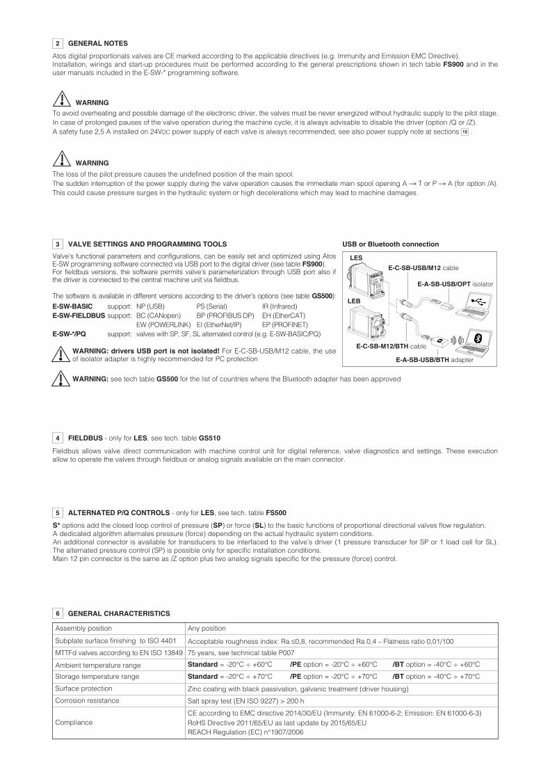
3 VALVE SETTINGS AND PROGRAMMING TOOLS
Valve's functional parameters and configurations, can be easily set and optimized using Atos E-SW programming software connected via USB port to the digital driver (see table FS900). For fieldbus versions, the software permits valve's parameterization through USB port also if the driver is connected to the central machine unit via fieldbus.
USB or Bluetooth connection
LES
LEB
E-C-SB-USB/M12 cable
E-A-SB-USB/OPT isolator
The software is available in different versions according to the driver’s options (see table GS500):
E-SW-BASIC support: NP (USB) PS (Serial) IR (Infrared) E-SW-FIELDBUS support: BC (CANopen) BP (PROFIBUS DP) EH (EtherCAT) EW (POWERLINK) EI (EtherNet/IP) EP (PROFINET) E-SW-*/PQ support: valves with SP, SF, SL alternated control (e.g. E-SW-BASIC/PQ)
WARNING: drivers USB port is not isolated! For E-C-SB-USB/M12 cable, the use of isolator adapter is highly recommended for PC protection
E-C-SB-M12/BTH cable
E-A-SB-USB/BTH adapter
WARNING: see tech table GS500 for the list of countries where the Bluetooth adapter has been approved
The loss of the pilot pressure causes the undefined position of the main spool. The sudden interruption of the power supply during the valve operation causes the immediate main spool opening A n T or P n A (for option /A). This could cause pressure surges in the hydraulic system or high decelerations which may lead to machine damages.
WARNING
WARNING
To avoid overheating and possible damage of the electronic driver, the valves must be never energized without hydraulic supply to the pilot stage. In case of prolonged pauses of the valve operation during the machine cycle, it is always advisable to disable the driver (option /Q or /Z). A safety fuse 2,5 A installed on 24VDC power supply of each valve is always recommended, see also power supply note at sections . 15
5 ALTERNATED P/Q CONTROLS - only for LES, see tech. table FS500
S* options add the closed loop control of pressure (SP) or force (SL) to the basic functions of proportional directional valves flow regulation. A dedicated algorithm alternates pressure (force) depending on the actual hydraulic system conditions. An additional connector is available for transducers to be interfaced to the valve’s driver (1 pressure transducer for SP or 1 load cell for SL). The alternated pressure control (SP) is possible only for specific installation conditions. Main 12 pin connector is the same as /Z option plus two analog signals specific for the pressure (force) control.
6 GENERAL CHARACTERISTICS
Assembly position Any position
Subplate surface finishing to ISO 4401 Acceptable roughness index: Ra ≤0,8, recommended Ra 0,4 – Flatness ratio 0,01/100
MTTFd valves according to EN ISO 13849 75 years, see technical table P007
Ambient temperature range Standard = -20°C ÷ +60°C /PE option = -20°C ÷ +60°C /BT option = -40°C ÷ +60°C
Storage temperature range Standard = -20°C ÷ +70°C /PE option = -20°C ÷ +70°C /BT option = -40°C ÷ +70°C
Surface protection Zinc coating with black passivation, galvanic treatment (driver housing)
Corrosion resistance Salt spray test (EN ISO 9227) > 200 h
ComplianceCE according to EMC directive 2014/30/EU (Immunity: EN 61000-6-2; Emission: EN 61000-6-3) RoHS Directive 2011/65/EU as last update by 2015/65/EU REACH Regulation (EC) n°1907/2006

FS340
7 HYDRAULIC CHARACTERISTICS - based on mineral oil ISO VG 46 at 50 °C
8 ELECTRICAL CHARACTERISTICS
Note: a maximum time of 800 ms (depending on communication type) have be considered between the driver energizing with the 24 VDC power supply and when the valve is ready to operate. During this time the current to the valve coils is switched to zero.
9 SEALS AND HYDRAULIC FLUIDS - for other fluids not included in below table, consult our technical office
Seals, recommended fluid temperature NBR seals (standard) = -20°C ÷ +60°C, with HFC hydraulic fluids = -20°C ÷ +50°C FKM seals (/PE option) = -20°C ÷ +80°C HNBR seals (/BT option) = -40°C ÷ +60°C, with HFC hydraulic fluids = -40°C ÷ +50°C
Recommended viscosity 20÷100 mm2/s - max allowed range 15 ÷ 380 mm2/s
Hydraulic fluid Suitable seals type Classification Ref. Standard
Mineral oils NBR, FKM, HNBR HL, HLP, HLPD, HVLP, HVLPD DIN 51524
Flame resistant without water FKM HFDU, HFDRISO 12922
Flame resistant with water NBR, HNBR HFC
Max fluid contamination level
see also filter section at www.atos.com or KTF catalog
normal operation longer life
ISO4406 class 18/16/13 NAS1638 class 7 ISO4406 class 16/14/11 NAS1638 class 5
Power supplies Nominal : +24 VDC Rectified and filtered : VRMS = 20 ÷ 32 VMAX (ripple max 10 % VPP)
Max power consumption 50 W
Max. solenoid current 2,6 A
Coil resistance R at 20°C 3 ÷ 3,3 Ω
Analog input signals Voltage: range ±10 VDC (24 VMAX tollerant) Input impedance: Ri > 50 kΩ Current: range ±20 mA Input impedance: Ri = 500 Ω
Monitor outputs Output range: voltage ±10 VDC @ max 5 mA current ±20 mA @ max 500 Ω load resistance
Enable input Range: 0 ÷ 5 VDC (OFF state), 9 ÷ 24 VDC (ON state), 5 ÷ 9 VDC (not accepted); Input impedance: Ri > 10 kΩ
Fault output Output range: 0 ÷ 24 VDC (ON state > [power supply - 2 V] ; OFF state < 1 V ) @ max 50 mA; external negative voltage not allowed (e.g. due to inductive loads)
Pressure/Force transducer power supply (only for SP, SL) +24VDC @ max 100 mA (E-ATR-8 see tech table GS465)
AlarmsSolenoid not connected/short circuit, cable break with current reference signal, over/under temperature, valve spool transducer malfunctions, alarms history storage function
Insulation classH (180°) Due to the occuring surface temperatures of the solenoid coils, the European standards ISO 13732-1 and EN982 must be taken into account
Protection degree to DIN EN60529 IP66 / IP67 with mating connectors
Duty factor Continuous rating (ED=100%)
Tropicalization Tropical coating on electronics PCB
Additional characteristicsShort circuit protection of solenoid’s current supply; 3 leds for diagnostic; spool position control (SN) or pressure/force control (SP, SL) by P.I.D. with rapid solenoid switching; protection against reverse polarity of power supply
Communication interfaceUSB Atos ASCII coding
CANopen EN50325-4 + DS408
PROFIBUS DP EN50170-2/IEC61158
EtherCAT, POWERLINK, EtherNet/IP, PROFINET IO RT / IRT EC 61158
Communication physical layernot insulated USB 2.0 + USB OTG
optical insulated CAN ISO11898
optical insulated RS485
Fast Ethernet, insulated 100 Base TX
Recommended wiring cable LiYCY shielded cables, see section 18
(1) With step reference input 0÷100% (2) With pilot pressure = 140 bar, see datailed diagrams in section 10.2
Ports P, A, T = 350 X = 350 Y � 10
Ports P, A, T = 420 X = 350 Y � 10
≤ 0,1
min: 40% of system pressure max 350 recommended 140 ÷ 160
± 0,1
zero point displacement < 1% at ΔT = 40°C
Size
Max pressure [bar]LIQZO
LIQZP
Nominal flow of pilot valve at Δp = 70 bar [l/min]
Leakage of pilot valve at P = 100 bar [l/min]
Piloting pressure [bar]
Piloting volume [cm3]
Piloting flow (1) [l/min]
Response time 0 ÷ 100% step signal (2) [ms]
Hysteresis [% of the max regulation]
Repeatability [% of the max regulation]
Thermal drift
185 260 500
2,16
6,5
21
25
330 470 850
7,2
20
22
32
420 590 1050
8,9
25
22
40
780 1100 2000
17,7
43
25
50
1250 1750 3100
33,8
68
30
63
2100 3000 5000
42,7
76
34
80
4 0,2
8 0,2
28 0,5
40 0,7
100 0,7
100 0,7
Δp = 5 bar Δp = 10 bar
Max permissible flow
Nominal flow Δp P-A or A-T [l/min]
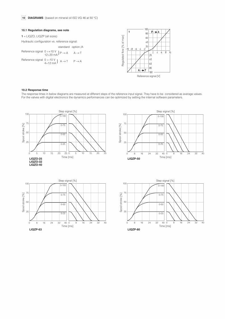
10 DIAGRAMS (based on mineral oil ISO VG 46 at 50 °C)
10.1 Regulation diagrams, see note 1 = LIQZO, LIQZP (all sizes)
Reg
ulat
ed fl
ow [
% o
f max
]
Reference signal [V]
1
Hydraulic configuration vs. reference signal: standard option /A
Reference signal 0 ÷+10 V P n A A n T 12÷20 mA Reference signal 0 ÷-10 V A n T P n A 4÷12 mA
10.2 Response time The response times in below diagrams are measured at different steps of the reference input signal. They have to be considered as average values. For the valves with digital electronics the dynamics performances can be optimized by setting the internal software parameters.
Time [ms] Time [ms]
Time [ms]
Sp
ool s
trok
e [%
]
Sp
ool s
trok
e [%
]
Sp
ool s
trok
e [%
]
Step signal [%] Step signal [%]
Step signal [%]
0-100
0-75
0-50
0-25
0-100
0-75
0-50
0-25
0-100
0-75
0-50
0-25
Time [ms]
Sp
ool s
trok
e [%
]
Step signal [%]
0-100
0-75
0-50
0-25
}
}
LIQZO-25 LIQZO-32 LIQZO-40
LIQZP-50
LIQZP-63 LIQZP-80
100
75
50
25
0 5 1510 20 25 0 5 1510 20 25
100
75
50
25
0 8 2416 32 40 0 8 2416 32 40
100
75
50
25
0 8 2416 32 40 0 8 2416 32 40
100
75
50
25
0 8 2416 32 40 0 8 2416 32 40

FS340
10.3 Pressure gain diagram
PA
Am
plit
ude
ratio
[d
B]
Frequency [Hz]
3 43 4
Pha
se [
deg
rees
]
Am
plit
ude
ratio
[d
B]
5 65 6
Pha
se [
deg
rees
]
Frequency [Hz]
10.4 Bode diagrams
Am
plit
ude
ratio
[d
B]
Frequency [Hz]
1 21 2 P
hase
[d
egre
es]
7 87 8
9 109 10
11 1211 12
1 = LIQZO-L*-253L4: ± 90% 2 = LIQZO-L*-253L4: ± 5% 3 = LIQZO-L*-323L4: ± 90% 4 = LIQZO-L*-323L4: ± 5%
5 = LIQZO-L*-403L4: ± 90% 6 = LIQZO-L*-403L4: ± 5% 7 = LIQZP-L*-503L4: ± 90% 8 = LIQZP-L*-503L4: ± 5%
9 = LIQZP-L*-633L4: ± 90% 10 = LIQZP-L*-633L4: ± 5% 11 = LIQZP-L*-803L4: ± 90% 12 = LIQZP-L*-803L4: ± 5%
Pre
ssur
e at
por
t A [
% o
f inl
et p
ress
ure]
Spool stroke [%]
100
90
80
70
60
50 40
30 20 10
0
-4-6 -242 6
+2
0
-3
+2
0
-3
10 10050
90°
45°
0°
90°
45°
0°10 10050
+2
0
-3
90°
45°
0°10 10050

AIR BLEEDING14
Sizes 63 to 80Size 50Size 25 to 40
SP
MB
MA
SP
MB
MA
SP
MB
MA
6
1
2
1
62
6
1
2
13 POSSIBLE COMBINED OPTIONS
12 ELECTRONICS OPTIONS
F = This option permits to monitor the eventual fault condition of the driver, as for example the solenoid short circuit/not connected, reference signal cable broken for option /I, spool position transducer broken, etc. - see 13.7 for signal specifications.
I = This option provides 4 ÷ 20 mA current reference and monitor signals, instead of the standard 0 ÷ 10 VDC. Input signal can be reconfigured via software selecting between voltage and current, within a maximum range of ±10 VDC or ±20 mA. It is normally used in case of long distance between the machine control unit and the valve or where the reference signal can be affected by electrical noise; the valve functioning is disabled in case of reference signal cable breakage.
Q = This option permits to inhibit the valve function without removing the power supply to the driver. Upon disable command the current to the solenoid is zeroed and the valve’s spool moves to rest position. The option /Q is suggested for all cases where the valve has to be frequently inhibited during the machine cycle – see 13.5 for signal spe-cifications.
Z = This option provides, on the 12 pin main connector, the following additional features: Fault output signal - see above option /F Enable input signal - see above option /Q Repeat enable output signal - only for LEB (see 13.6)
Power supply for driver’s logics and communication - only for LES (see 13.2)
C = This option is available to connect pressure (force) transducers with 4 ÷ 20 mA current output signal, instead of the standard ±10 VDC. Input signal can be reconfigured via software selecting between voltage and current, within a maximum range of ±10 VDC or ±20 mA.
11 HYDRAULIC OPTIONS
A option A = The standard valve version provides the hydraulic configuration A-T of main spool in
absence of electric power supply to the valve. The option /A provides the reverse configuration P-A of main spool in absence of
electric power supply to the valve. This execution is particularly requested in vertical presses for safety reasons, becau-
se in case of electric power breakdown the P-A configuration of the main spool pre-vents the uncontrolled and dangerous downstroke of the press ram.
LEB-SN, LES-SN /AF, /AI, /AQ, /AZ, /FI, /IQ, /IZ, /AFI, /AIQ, /AIZ
LES-SP, SL /AC, /CI, /ACI
1 Plugged port - do not open
2 Air bleeding:
N° 2 plugs G1/4”
At the machine commissioning it is advisable to bleed the air from piloting chambers, by loosening the 2 plugs shown in the picture.
Operate the valve for few seconds at low pressure and then lock the plugs.

FS340
15.11 Multiple PID selection (D_IN0 and D_IN1) - only NP execution for LES-SP, SL
Two on-off input signals are available on the main connector to select one of the four pressure (force) PID parameters setting, stored into the driver.
Switching the active setting of pressure PID during the machine cycle allows to optimize the system dynamic response in different hydraulic working conditions (volume, flow, etc.).
Supply a 24 VDC or a 0 VDC on pin 9 and/or pin 10, to select one of the PID settings as indica-ted by binary code table at side. Gray code can be selected by software.
PID SET SELECTION
PIN SET 1 SET 2 SET 3 SET 4
9 0 24 VDC 0 24 VDC
10 0 0 24 VDC 24 VDC
15 POWER SUPPLY AND SIGNALS SPECIFICATIONS
Generic electrical output signals of the valve (e.g. fault or monitor signals) must not be directly used to activate safety functions, like to switch-ON/OFF the machine’s safety components, as prescribed by the European standards (Safety requirements of fluid technology systems and components-hydraulics, ISO 4413).
15.1 Power supply (V+ and V0)
The power supply must be appropriately stabilized or rectified and filtered: apply at least a 10000 μF/40 V capacitance to single phase rectifiers or a 4700 μF/40 V capacitance to three phase rectifiers. In case of separate power supply see 15.2.
15.2 Power supply for driver’s logic and communication (VL+ and VL0) - only for /Z option and LES-SP, SL with fieldbus
The power supply for driver’s logic and communication must be appropriately stabilized or rectified and filtered: apply at least a 10000 μF/40 V capacitance to single phase rectifiers or a 4700 μF/40 V capacitance to three phase rectifiers.
The separate power supply for driver's logic on pin 9 and 10, allow to remove solenoid power supply from pin 1 and 2 maintaining active the diagnostics, USB and fieldbus communications.
A safety fuse is required in series to each power supply: 2,5 A time lag fuse.
A safety fuse is required in series to each driver’s logic and communication power supply: 500 mA fast fuse.
15.3 Flow reference input signal (Q_INPUT+)
The driver controls in closed loop the valve spool position proportionally to the external reference input signal. Reference input signal is factory preset according to selected valve code, defaults are 0 ÷ 10 VDC for standard and 4 ÷ 20 mA for /I option. Input signal can be reconfigured via software selecting between voltage and current, within a maximum range of ±10 VDC or ± 20 mA. Drivers with fieldbus interface can be software set to receive reference signal directly from the machine control unit (fieldbus reference).
Analog reference input signal can be used as on-off commands with input range 0 ÷ 24VDC.
15.4 Pressure or force reference input signal (F_INPUT+) - only for LES-SP, SL
Functionality of F_INPUT+ signal (pin 7), is used as reference for the driver pressure/force closed loop (see tech. table FS500). Reference input signal is factory preset according to selected valve code, defaults are 0 ÷ 10 VDC for standard and 4 ÷ 20 mA for /I option. Input signal can be reconfigured via software selecting between voltage and current, within a maximum range of ±10 VDC or ± 20 mA. Drivers with fieldbus interface can be software set to receive reference signal directly by the machine control unit (fieldbus reference). Analog reference input signal can be used as on-off commands with input range 0 ÷ 24VDC.
15.5 Flow monitor output signal (Q_MONITOR) - not for /F
The driver generates an analog output signal proportional to the actual spool position of the valve; the monitor output signal can be software set to show other signals available in the driver (e.g. analog reference, fieldbus reference, pilot spool position).
Monitor output signal is factory preset according to selected valve code, defaults are ±10 VDC for standard and 4 ÷ 20 mA for /I option. Output signal can be reconfigured via software selecting between voltage and current, within a maximum range of ±10 VDC or ± 20 mA.
15.6 Pressure or force monitor output signal (F_MONITOR) - only for LES-SP, SL
The driver generates an analog output signal proportional to alternated pressure/force control; the monitor output signal can be software set to show other signals available in the driver (e.g. analog reference, force reference).
Monitor output signal is factory preset according to selected valve code, defaults are 0 ÷ 10 VDC for standard and 4 ÷ 20 mA for /I option. Output signal can be reconfigured via software selecting between voltage and current, within a maximum range of ±10 VDC or ± 20 mA.
15.7 Enable input signal (ENABLE) - not for standard and /F
To enable the driver, supply a 24 VDC on pin 3 (pin C): Enable input signal allows to enable/disable the current supply to the solenoid, without removing the electrical power supply to the driver; it is used to active the communication and the other driver functions when the valve must be disabled for safety reasons. This condition does not comply with norms IEC 61508 and ISO 13849.
Enable input signal can be used as generic digital input by software selection.
15.8 Repeat enable output signal (R_ENABLE) - only for LEB with /Z option
Repeat enable is used as output repeater signal of enable input signal (see 15.7).
15.9 Fault output signal (FAULT) - not for standard and /Q
Fault output signal indicates fault conditions of the driver (solenoid short circuits/not connected, reference signal cable broken for 4 ÷ 20 mA input, spool position transducer cable broken, etc.). Fault presence corresponds to 0 VDC, normal working corresponds to 24 VDC.
Fault status is not affected by the Enable input signal. Fault output signal can be used as digital output by software selection.
15.10 Remote pressure/force transducer input signal - only for LES-SP, SL
Analog remote pressure transducers or load cell can be directly connected to the driver (see 16.4). Analog input signal is factory preset according to selected valve code, defaults are ±10 VDC for standard and 4 ÷ 20 mA for /C option. Input signal can be reconfigured via software selecting between voltage and current, within a maximum range of ±10 VDC or ± 20 mA. Refer to pressure/force transducer characteristics to select the transducer type according to specific application requirements (see tech
table FS500).

EH, EW, EI, EP fieldbus execution, connector - M12 - 4 pin
PIN SIGNAL TECHNICAL SPECIFICATION (1)1 TX+ Transmitter2 RX+ Receiver3 TX- Transmitter4 RX- Receiver
Housing SHIELD
BC fieldbus execution, connector - M12 - 5 pin
PIN SIGNAL TECHNICAL SPECIFICATION (1)1 CAN_SHLD Shield2 not used - pass-through connection (2)3 CAN_GND Signal zero data line4 CAN_H Bus line (high)5 CAN_L Bus line (low)
USB connector - M12 - 5 pin always present
PIN SIGNAL TECHNICAL SPECIFICATION (1)1 +5V_USB Power supply2 ID Identification3 GND_USB Signal zero data line 4 D- Data line - 5 D+ Data line +
BP fieldbus execution, connector - M12 - 5 pin
PIN SIGNAL TECHNICAL SPECIFICATION (1)1 +5V Termination supply signal2 LINE-A Bus line (high)3 DGND Data line and termination signal zero4 LINE-B Bus line (low)5 SHIELD
16.3 Communications connectors -
(1) Shield connection on connector’s housing is recommended (2) Pin 2 can be fed with external +5V supply of CAN interface
1 2
3
4 5
6
7
8 9
10
11
PE
Input - power supply Gnd - power supply
Input - on/off signal
Input - analog signal Software selectable Input - analog signal Output - analog signal Software selectable Gnd - analog signal Input - analog signal Software selectable Output - on/off signal Output - analog signal Software selectable Input - power supply Input - on/off signal Gnd - power supply Input - on/off signal
Output - on/off signal
PIN TECHNICAL SPECIFICATIONS NOTESLEB-SN /Z LES-SN /Z Fieldbus NPPower supply 24 VDC Power supply 0 VDC
Enable (24 VDC) or disable (0 VDC) the valve
Flow reference input signal: ±10 VDC / ±20 mA maximum range Defaults are 0 ÷ 10 VDC for standard and 4 ÷ 20 mA for /I option Negative reference input signal for Q_INPUT+ and F_INPUT+ Flow monitor output signal: ±10 VDC / ±20 mA maximum range Defaults are 0 ÷ 10 VDC for standard and 4 ÷ 20 mA for /I option Analog ground Do not connect Pressure/Force reference input signal: ±10 VDC / ±20 mA maximum range Defaults are ±10 VDC for standard and 4 ÷ 20 mA for /I option Repeat enable, output repeter signal of enable input, referred to V0 Do not connect Pressure/Force monitor output signal: ±10 VDC / ±20 mA maximum range Defaults are ±10 VDC for standard and 4 ÷ 20 mA for /I option Do not connect Power supply 24 VDC for driver’s logic and communication Multiple pressure/force PID selection, referred to V0 Do not connect Power supply 0 VDC for driver’s logic and communication Multiple pressure/force PID selection, referred to V0
Fault (0 VDC) or normal working (24 VDC)
Internally connected to the driver housing
LES-SP, SL
A B
C
D
E F
G
Input - power supply Gnd - power supply Gnd - analog signal Input - on/off signal Input - analog signal Software selectable Input - analog signal Output - analog signal Software selectable Output - on/off signal
TECHNICAL SPECIFICATIONS NOTESStandard /Q /F
Power supply 24 VDC Rectified and filtered: VRMS = 20 ÷ 32 VMAX (ripple max 10 % VPP) Power supply 0 VDC Analog ground Enable (24 VDC) or disable (0 VDC) the valve, referred to V0 Flow reference input signal: ±10 VDC / ±20 mA maximum range Defaults are 0 ÷ 10 VDC for standard and 4 ÷ 20 mA for /I option Negative reference input signal for Q_INPUT+ Flow monitor output signal: ±10 VDC / ±20 mA maximum range Defaults are 0 ÷ 10 VDC for standard and 4 ÷ 20 mA for /I option Fault (0 VDC) or normal working (24 VDC) Internally connected to the driver housing
16.1 Main connector signals - 7 pin - standard, /F and /Q options
16 ELECTRONIC CONNECTIONS AND LEDS
16.2 Main connector signals - 12 pin - /Z option and SP, SL
PIN
V+ V0 AGND AGND
ENABLE
Q_INPUT+
INPUT- Q_MONITOR referred to: AGND V0
FAULT EARTH
V+ V0 ENABLE referred to: V0 VL0 VL0 V0
Q_INPUT+ INPUT- Q_MONITOR referred to: AGND VL0 VL0 V0 AGND
NC
F_INPUT+
R_ENABLE
NC F_MONITOR referred to: VL0 V0
NC VL+
D_IN0 NC
VL0 D_IN1
FAULT referred to: V0 VL0 VL0 V0 EARTH

16.5 LEB connections layout
MAIN CONNECTORS
A2 A4A3A1A2
A4
A1
A3
Ø 2
8Ø
29
~ 93
~ 100
PG13.5
PG16
Ø 2
8
Ø 2
9
~ 60
~ 76PG11
PG11
B
35.5
~ 23
~ 50
Ø15
ZM-12P - 12 pin - metallic (1)
ZH-12P - 12 pin - plastic
ZM-7P - 7 pin - metallic (1)
ZH-7P - 7 pin - plastic
TRANSDUCER AND USB CONNECTOR
E-C-SB-USB/M12 USB CABLE
cable lenght 4m
SPOOL POSITION MAIN STAGE
male - 7 pin (2) male - 12 pin (2)
USB
Standard, /Q, /F /Z
(1) Use of metallic connectors is strongly recommended in order to fulfill EMC requirements (2) Pin layout always referred to driver’s view
B
13.5
Ø14
PLASTIC PROTECTION CAP - supplied with the valves
USB cap
Tightening torque: 0,6 Nm
DO NOT REMOVE
(1) Single/double transducer configuration is software selectable
Remote pressure transducers connection - example
1 VF+ 24V 1 V+ 1 V+
2 TR1 4 TR 3 TR
3 AGND 3 V0 4 NC
4 NC 2 NC 2 NC
5 NC 5 NC 5 NC
for SP option
ZH-5PM/1.5 ZBE-08 1
4
2
3
5
to be connected to pressure transducer E-ATR
Voltage signal Current signal1
2
3
4
5
Note: pin layout always referred to driver’s view
to be connected to electronic driver
16.4 Remote pressure transducer connector - M12 - 5 pin - only for SP, SL
PIN SIGNAL TECHNICAL SPECIFICATION Voltage Current
1 VF +24V Power supply +24VDC Connect Connect
2 TR Signal transducer ±10 VDC / ±20 mA maximum range, software selectable Defaults are ±10 VDC for standard and 4 ÷ 20 mA for /C option Connect Connect
3 AGND Common GND for transducer power and signals Connect /
4 NC Not Connect / /
5 NC Not Connect / /
FS340
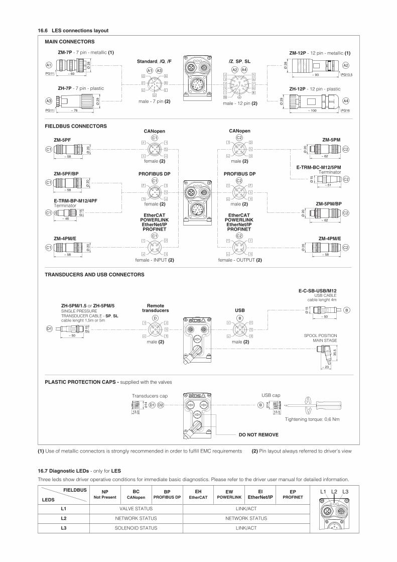
16.6 LES connections layout
Three leds show driver operative conditions for immediate basic diagnostics. Please refer to the driver user manual for detailed information.
16.7 Diagnostic LEDs - only for LES
NP Not Present
BC CANopen
BP PROFIBUS DP
EH EtherCAT
EW POWERLINK
EI EtherNet/IP
EP PROFINET
L1 VALVE STATUS LINK/ACT
L2 NETWORK STATUS NETWORK STATUS
L3 SOLENOID STATUS LINK/ACT
FIELDBUS
LEDS
L1 L2 L3
MAIN CONNECTORS
A2
A4
A1A2
A3
A4A3A1
Ø 2
8Ø
29
~ 93
~ 100
PG13.5
PG16
Ø 2
8
Ø 2
9
~ 60
~ 76PG11
PG11
Ø 1
5
~ 62
Ø 2
0
~ 51
~ 62
Ø 2
0Ø
20
~ 58
~ 46
Ø 2
0Ø
20
~ 58
~ 58
Ø 1
5
Ø 2
0
~ 58
D
BØ
15
~ 50
35.5
~ 23
~ 50
Ø 1
5
BD2D1
13.5
Ø14
13.5
Ø14
ZM-12P - 12 pin - metallic (1)
ZH-12P - 12 pin - plastic
ZM-7P - 7 pin - metallic (1)
ZH-7P - 7 pin - plastic
FIELDBUS CONNECTORS
PROFIBUS DP
ZM-5PM/BP
ZM-5PMZM-5PF
ZM-4PM/E
CANopen
ZM-5PF/BPE-TRM-BC-M12/5PM
Terminator
male (2)female (2)
female - INPUT (2)
ZM-4PM/E
E-TRM-BP-M12/4PF Terminator
TRANSDUCERS AND USB CONNECTORS
E-C-SB-USB/M12 USB CABLE
cable lenght 4m
male (2) male (2)
PROFIBUS DP
EtherCAT POWERLINK EtherNet/IP PROFINET
CANopen
PLASTIC PROTECTION CAPS - supplied with the valves
USB cap
Tightening torque: 0,6 Nm
Transducers cap
DO NOT REMOVE
female - OUTPUT (2)
EtherCAT POWERLINK EtherNet/IP PROFINET
male - 7 pin (2) male - 12 pin (2)
Remote transducers
USB
Standard, /Q, /F /Z, SP, SL
ZH-5PM/1.5 or ZH-5PM/5 SINGLE PRESSURE TRANSDUCER CABLE - SP, SL cable lenght 1,5m or 5m
male (2)female (2)
(1) Use of metallic connectors is strongly recommended in order to fulfill EMC requirements (2) Pin layout always referred to driver’s view
SPOOL POSITION MAIN STAGE

18 CONNECTORS CHARACTERISTICS - to be ordered separately
CONNECTOR TYPE POWER SUPPLY POWER SUPPLY
CODE ZM-7P ZH-7P
Type 7pin female straight circular 7pin female straight circularStandard According to MIL-C-5015 According to MIL-C-5015Material Metallic Plastic reinforced with fiber glassCable gland PG11 PG11
Recommended cable LiYCY 7 x 0,75 mm2 max 20 m (logic and power supply) or LiYCY 7 x 1 mm2 max 40 m (logic and power supply)
LiYCY 7 x 0,75 mm2 max 20 m (logic and power supply) or LiYCY 7 x 1 mm2 max 40 m (logic and power supply)
Conductor size up to 1 mm2 - available for 7 wires up to 1 mm2 - available for 7 wiresConnection type to solder to solderProtection (EN 60529) IP 67 IP 67
CONNECTOR TYPE POWER SUPPLY POWER SUPPLY
CODE ZM-12P ZH-12P
Type 12pin female straight circular 12pin female straight circularStandard DIN 43651 DIN 43651Material Metallic Plastic reinforced with fiber glassCable gland PG13,5 PG16
Recommended cable LiYCY 12 x 0,75 mm2 max 20 m (logic and power supply) LiYCY 10 x 0,14mm2 max 40 m (logic) LiYY 3 x 1mm2 max 40 m (power supply)
Conductor size 0,5 mm2 to 1,5 mm2 - available for 12 wires 0,14 mm2 to 0,5 mm2 - available for 9 wires
0,5 mm2 to 1,5 mm2 - available for 3 wires Connection type to crimp to crimpProtection (EN 60529) IP 67 IP 67
18.1 Main connectors - 7 pin
A3
A4
18.3 Fieldbus communication connectors
CONNECTOR TYPE BC CANopen (1) BP PROFIBUS DP (1) EH EtherCAT, EW POWERLINK, EI EtherNet/IP, EP PROFINET (2)
CODE ZM-5PF ZM-5PM ZM-5PF/BP ZM-5PM/BP ZM-4PM/E
Type 5 pin female straight circular
5 pin male straight circular
5 pin female straight circular
5 pin male straight circular
4 pin male straight circular
Standard M12 coding A – IEC 61076-2-101 M12 coding B – IEC 61076-2-101 M12 coding D – IEC 61076-2-101Material Metallic Metallic MetallicCable gland Pressure nut - cable diameter 6÷8 mm Pressure nut - cable diameter 6÷8 mm Pressure nut - cable diameter 4÷8 mmCable CANbus Standard (DR 303-1) PROFIBUS DP Standard Ethernet standard CAT-5Connection type screw terminal screw terminal terminal blockProtection (EN 60529) IP67 IP 67 IP 67
(1) E-TRM-** terminators can be ordered separately - see tech table GS500 (2) Internally terminated
18.2 Main connectors - 12 pin
17 IN / OUT FIELDBUS COMMUNICATION CONNECTORS
Two fieldbus communication connectors are always available for digital drivers executions BC, BP, EH, EW, EI, EP. This features allows considerable technical advantages in terms of installation simplicity, wirings reduction and also avoid the usage expensive T-connectors. For BC and BP executions the fieldbus connectors have an internal pass-through connection and can be used like end point of the fieldbus network, using an external terminator (see tech table GS500). For EH, EW, EI and EP executions the external terminators are not required: each connector is internally terminated.
BC and BP pass-through connection
fieldbus network
fieldbus interface
fieldbus network
CONNECTOR TYPE SP, SL - Single transducer
CODE ZH-5PM/1.5 ZH-5PM/5
Type 5 pin male straight circularStandard M12 coding A – IEC 61076-2-101Material Plastic
Cable gland Connector moulded on cables 1,5 m lenght 5 m lenght
Cable 5 x 0,25 mm2
Connection type molded cableProtection (EN 60529) IP 67
18.4 Pressure/Force transducer connectors - only for SP, SL
FS340
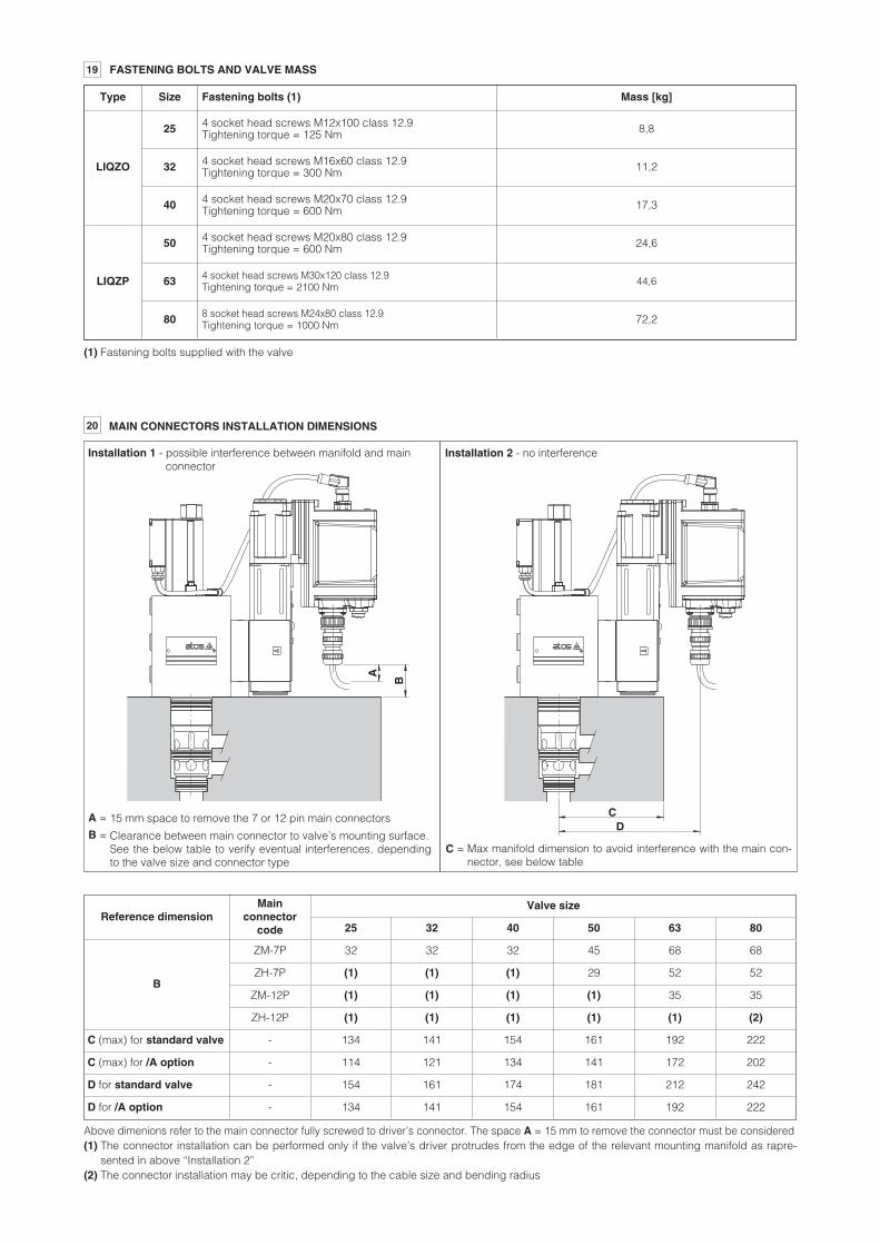
20 MAIN CONNECTORS INSTALLATION DIMENSIONS
(1) Fastening bolts supplied with the valve
Type Size Fastening bolts (1) Mass [kg]
LIQZO
25 4 socket head screws M12x100 class 12.9 Tightening torque = 125 Nm 8,8
32 4 socket head screws M16x60 class 12.9 Tightening torque = 300 Nm 11,2
40 4 socket head screws M20x70 class 12.9 Tightening torque = 600 Nm 17,3
LIQZP
50 4 socket head screws M20x80 class 12.9 Tightening torque = 600 Nm 24,6
63 4 socket head screws M30x120 class 12.9 Tightening torque = 2100 Nm 44,6
80 8 socket head screws M24x80 class 12.9 Tightening torque = 1000 Nm 72,2
19 FASTENING BOLTS AND VALVE MASS
Reference dimensionMain
connector code
Valve size
25 32 40 50 63 80
B
ZM-7P 32 32 32 45 68 68
ZH-7P (1) (1) (1) 29 52 52
ZM-12P (1) (1) (1) (1) 35 35
ZH-12P (1) (1) (1) (1) (1) (2)
C (max) for standard valve - 134 141 154 161 192 222
C (max) for /A option - 114 121 134 141 172 202
D for standard valve - 154 161 174 181 212 242
D for /A option - 134 141 154 161 192 222
Above dimenions refer to the main connector fully screwed to driver’s connector. The space A = 15 mm to remove the connector must be considered (1) The connector installation can be performed only if the valve’s driver protrudes from the edge of the relevant mounting manifold as rapre-
sented in above “Installation 2” (2) The connector installation may be critic, depending to the cable size and bending radius
Installation 1 - possible interference between manifold and main connector
A
B
CD
15 mm space to remove the 7 or 12 pin main connectors
Clearance between main connector to valve’s mounting surface. See the below table to verify eventual interferences, depending to the valve size and connector type
A =
B = Max manifold dimension to avoid interference with the main con-nector, see below table
C =
Installation 2 - no interference

21 INSTALLATION DIMENSIONS [mm]
Note: for mounting surface and cavity dimensions, see table P006
2
= Space to remove the connectors
= The dimensions of all connectors must be considered, see section 16.5 and 16.6 For main connectors installation, see also section . 20
1
LIQZO-LEB-253 LIQZO-LES-253
LIQZO-LEB-323 LIQZO-LES-323
LIQZO-LEB-**-403 LIQZO-LES-**-403
237
LIQZP-LEB-503 LIQZP-LES-503
110
80 92
15
85x85 20523
7
105
30 92
100X100 205
240
120
39
92
15
125x125 205
317
129
49
105
15
140x140 205
15
140
155 for SP, SL, EW - POWERLINK, EI - EtherNet/IP, EP - PROFINET IRT
140
155 for SP, SL, EW - POWERLINK, EI - EtherNet/IP, EP - PROFINET IRT
140
155 for SP, SL, EW - POWERLINK, EI - EtherNet/IP, EP - PROFINET IRT
140
155 for SP, SL, EW - POWERLINK, EI - EtherNet/IP, EP - PROFINET IRT
1
2
2
1
2
2
1
2
2
1
2
2
FS340

11/19
22 RELATED DOCUMENTATION
Note: for mounting surface and cavity dimensions, see table P006
2
= Space to remove the connectors
= The dimensions of all connectors must be considered, see section 16.5 and 16.6 For main connectors installation, see also section . 20
1
LIQZP-LEB-803 LIQZP-LES-803
LIQZP-LEB-633 LIQZP-LES-633
336
142
76 15
128
45
162
356
128
180x180 405
Ø250 405
150
165 for SP, SL, EW - POWERLINK, EI - EtherNet/IP, EP - PROFINET IRT
150
165 for SP, SL, EW - POWERLINK, EI - EtherNet/IP, EP - PROFINET IRT
1
2
2
15
1
2
2
FS001 Basics for digital electrohydraulics FS500 Digital proportional valves with P/Q control FS900 Operating and maintenance information for proportional valves GS500 Programming tools GS510 Fieldbus
K800 Electric and electronic connectors P006 Mounting surfaces and cavities for cartridge valves QB340 Quickstart for LEB valves commissioning QF340 Quickstart for LES valves commissioning