digital radiography 101 or how to be a digital radiography expert in 1 easy lesson by walter golub,...
TRANSCRIPT

Digital Radiography 101Digital Radiography 101oror
How to be a How to be a Digital Radiography Expert Digital Radiography Expert
in 1 Easy Lesson in 1 Easy Lesson
By Walter Golub, DMD

About This CourseAbout This Course This course is not intended to sell you This course is not intended to sell you on the idea of going digital. on the idea of going digital.
Claims being made can be confusing, if Claims being made can be confusing, if not misleading.not misleading.
This course will help the clinician This course will help the clinician understand how the technology works.understand how the technology works.
A Brief HistoryA Brief History Late 1980’s – the first sensorsLate 1980’s – the first sensors
Very largeVery large Used TV – not computerUsed TV – not computer No way to store or manipulate the images electronically.No way to store or manipulate the images electronically. Very expensiveVery expensive
Mid 1990s’s – the next generationMid 1990s’s – the next generation Multiple size sensors (more like film)Multiple size sensors (more like film) Personal computer became affordablePersonal computer became affordable Sensor prices became affordableSensor prices became affordable
TodayToday Many different systemsMany different systems Technology is provenTechnology is proven How do you choose?How do you choose?

2 Kinds of Digital Radiography2 Kinds of Digital Radiography
Phosphor Plates – ‘just like film’ in many regards, except Phosphor Plates – ‘just like film’ in many regards, except more time consuming and more expensivemore time consuming and more expensive..
Research shows phosphor plates need to be replaced after as Research shows phosphor plates need to be replaced after as few as 50 uses* – few as 50 uses* – making it far more expensive .making it far more expensive .
This technology is not covered in this courseThis technology is not covered in this course
Direct SensorsDirect Sensors This is the technology that I recommend.This is the technology that I recommend.
Citation: Bedard A, Davis TD, Angelopoulos C. Storage Phosphor Plates: How Durable are they as a DigitalDental Radiographic System? J Contemp Dent Pract 2004 May;(5)2:057-069.

Digital System BasicsDigital System Basics
Every Digital Radiography System Every Digital Radiography System Consists of these 6 components:Consists of these 6 components: X-ray SourceX-ray Source SensorSensor InterfaceInterface ComputerComputer MonitorMonitor SoftwareSoftware

Digital System BasicsDigital System Basics
Interface
Monitor
Personal Computer
Software
X-ray SourceSensor

Notes On Image QualityNotes On Image Quality
The sensor is the single most important The sensor is the single most important component in regards to image quality.component in regards to image quality.
The monitor is the second most important.The monitor is the second most important.
Software cannot compensate for a poor Software cannot compensate for a poor raw image (the image created by the raw image (the image created by the sensor) – Garbage in = Garbage Outsensor) – Garbage in = Garbage Out
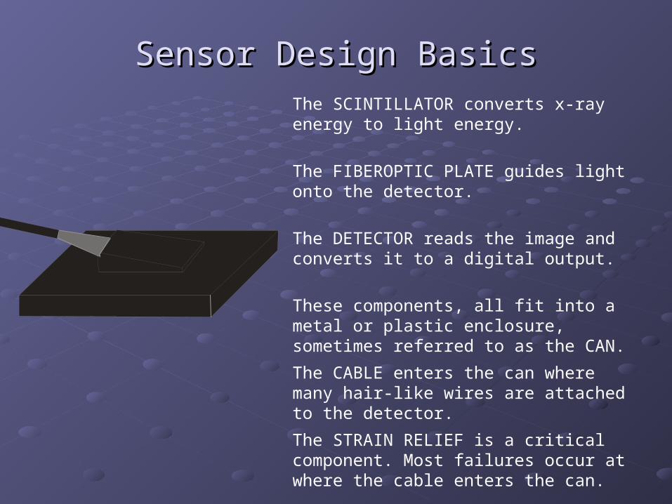
Sensor Design BasicsSensor Design Basics
The DETECTOR reads the image and converts it to a digital output.
The FIBEROPTIC PLATE guides light onto the detector.
The SCINTILLATOR converts x-ray energy to light energy.
These components, all fit into a metal or plastic enclosure, sometimes referred to as the CAN.
The CABLE enters the can where many hair-like wires are attached to the detector.
The STRAIN RELIEF is a critical component. Most failures occur at where the cable enters the can.

The ScintillatorThe Scintillator
The detectors in digital radiography sensors are not digital radiography sensors are not sensitive to x-rayssensitive to x-rays, they are sensitive to visible light. The SCINTILLATOR converts x-ray energy to light energy.
When x-rays pass through a SCINTILLATOR, it emits a glow of visible light. The more or less radiation – the brighter or dimmer the glow. This converts the x-ray pattern of the radiograph into a pattern of visible light.
scintillator

The Fiberoptic PlateThe Fiberoptic PlateThe FIBEROPTIC PLATE (F.O.P.) serves 3 very important functions.
11. It protects the detector (CCD or CMOS) from being damaged by the high energy x-rays.
22. It prevents the detector (CCD or CMOS) from reading the x-ray energy as light (and therefore interpreting it as image data)
33. It takes the image created by the scintillator and focuses it on the detector, keeping the image sharp and coherent.
F.O.P.

Radiation passes through the sensor
The scintillator glows (in all directions). The brightness of a given spot is in proportion to the x-ray energy that hits it.
The FOP guides the light from the scintillator down to the pixel.
The Fiberoptic PlateThe Fiberoptic Plate
Sensors without a Fiber Optic Plate can be made much thinner, but they lack all of the advantages that the FOP provides:
1. Protection of the detector from damaging x-rays
2. Protection from false image data caused by x-rays being ‘read’ by the detector.
3. The focused transmission of the scintillator image onto the pixels.
The Detector (CCD or CMOS)The Detector (CCD or CMOS)CCD and CMOS refer to either the design (CCD) or the CCD and CMOS refer to either the design (CCD) or the material (CMOS) of the detector.material (CMOS) of the detector.
Several years ago – CCD were considered a superior detector, Several years ago – CCD were considered a superior detector, now CMOS is considered equal, if not better.now CMOS is considered equal, if not better.
Either technology is capable of producing excellent image Either technology is capable of producing excellent image quality.quality.
There is only ONE significant advantage of one over the other There is only ONE significant advantage of one over the other – CMOS requires very little power compared to CCD.– CMOS requires very little power compared to CCD.
This means CMOS systems generally have smaller interfaces and/or This means CMOS systems generally have smaller interfaces and/or more flexible installation options (i.e. no external power needed)more flexible installation options (i.e. no external power needed)
Detector TYPE is Detector TYPE is not importantnot important

How the Detector Creates an How the Detector Creates an ImageImage
The Original Image

1
11
11
11
111
11
11
11
1
11
11
11
111
11
11
11
1
11
11
12
222
11
11
11
1
11
12
2
22
11
11
1
11
22
2
21
11
1
11
2
46
5
4
6
21
11
1
12
11
7
45
2
11
1
12
6
2
11
1
12
3
6
2
11
1
12
69
54
2
11
1
11
2
4
51
21
11
1
11
22
2
21
11
1
11
11
2
22
11
11
1
11
11
12
222
11
11
11
1
11
11
11
111
11
11
11
1
11
11
11
111
11
11
11
38
333
33
33
3 3
3
3
3
3
3
3
3
3
8
3
3
3
3
3 3 3
3
3 3
3
3
3
3
3
3
3
3
3
33
3
3 3
3 3 3 3
3 3 3 3
3
3
33 3
How the Detector Creates an How the Detector Creates an ImageImage
The scintillator glows in proportion to the radiation that hits it. This creates a pattern of bright and dim pixels.
This light intensity is measured by each pixel, based upon the level of light/dark the pixel ‘sees’.
It converts that quantity into a number.
For purposes of this example we’ll use the numbers from 1 to 9.

1
11
11
11
111
11
11
11
1
11
11
11
111
11
11
11
1
11
11
12
222
11
11
11
1
11
12
2
22
11
11
1
11
22
2
21
11
1
11
2
46
5
4
6
21
11
1
12
1
7
45
2
11
1
12
6
2
11
1
12
3
6
2
11
1
12
69
54
2
11
1
11
2
4
51
21
11
1
11
22
2
21
11
1
11
11
2
22
11
11
1
11
11
12
222
11
11
11
1
11
11
11
111
11
11
11
1
11
11
11
111
11
11
11
38
333
33
33
3 3
3
3
3
3
3
3
3
3
8
3
3
3
3
3 3 3
3
3 3
3
3
3
3
3
3
3
3
3
33
3
3 3
3 3 3 3
3 3 3 3
3
3
33 3
How the Detector Creates an How the Detector Creates an ImageImage
Here is the pixel value map without the original image overlaid.
Each of the pixel values is then sent to the computer.
Since the computer ‘knows’ the location of each pixel…

How the Detector Creates an How the Detector Creates an ImageImage
It is a simple matter to reconstruct the pixel value data into a similar size grid.
The jagged effect is caused when the pixel lies along a transition in density. This effect is called ‘pixelization’
This image may not look very good, but you have to consider the scale involved…

So you can begin to realize how excellent these sensors are…
This square would be far less than a millimeter across…
<1 mm
How the Detector Creates an How the Detector Creates an ImageImage
At resolving extremely minute details…
If this image were taken by a good digital sensor…
As small as 8/100th of a mm…
Specifications and Sensor Image Specifications and Sensor Image QualityQuality
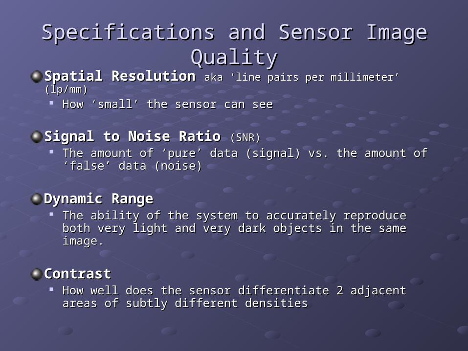
Spatial ResolutionSpatial Resolution aka ‘line pairs per millimeter’ (lp/mm)aka ‘line pairs per millimeter’ (lp/mm) How ‘small’ the sensor can seeHow ‘small’ the sensor can see
Signal to Noise RatioSignal to Noise Ratio (SNR)(SNR) The amount of ‘pure’ data (signal) vs. the amount of ‘false’ data The amount of ‘pure’ data (signal) vs. the amount of ‘false’ data
(noise)(noise)
Dynamic RangeDynamic Range The ability of the system to accurately reproduce both very light The ability of the system to accurately reproduce both very light
and very dark objects in the same image. and very dark objects in the same image.
ContrastContrast How well does the sensor differentiate 2 adjacent areas of subtly How well does the sensor differentiate 2 adjacent areas of subtly
different densitiesdifferent densities

Spatial Resolution aka ‘Line Pairs’Spatial Resolution aka ‘Line Pairs’
22 or 23 lp/mm = must be a ‘theoretical value’
12.5 lp/mm = the ability to see an Item of 0.04 mm diameter
This is a radiograph of a ‘line pair’ phantom.
Each pair of converging lines (1 light/1 dark) equals one ‘line pair’.
Ask a sales rep to create a 20+ lp/mm image in your office. THEY CAN’T
Many companies use this specification to ‘prove’ image quality.

Spatial Resolution aka ‘Line Pairs’ Spatial Resolution aka ‘Line Pairs’
Why so much confusion about this specification?Why so much confusion about this specification?
It’s easy to ‘visualize’.It’s easy to ‘visualize’. Companies that promote this specification use it to convince a doctor of image Companies that promote this specification use it to convince a doctor of image
quality quality without taking a single live imagewithout taking a single live image in their office.in their office.
Why doesn’t lp/mm work as an indicator of image quality?Why doesn’t lp/mm work as an indicator of image quality?
Increasing spatial resolution is easy:Increasing spatial resolution is easy: use use lots and lotslots and lots of of very small pixelsvery small pixels
The problem:The problem: a small pixel a small pixel generates more noisegenerates more noise than a larger pixel than a larger pixel
lots and lots of small pixels = lots and lots of small pixels = lots and lots of NOISElots and lots of NOISE

Spatial Resolution aka ‘Line Pairs’ Spatial Resolution aka ‘Line Pairs’
A very A very misleadingmisleading specification. specification.
FACT – ‘High resolution’ sensors (20+ lp/mm) have FACT – ‘High resolution’ sensors (20+ lp/mm) have inherently more noiseinherently more noise. This is a . This is a
physical attribute of small pixels that cannot be avoided. physical attribute of small pixels that cannot be avoided. Noise hurts image qualityNoise hurts image quality..
FACT - ‘High resolution’ sensors FACT - ‘High resolution’ sensors require more radiationrequire more radiation to get good images – due to to get good images – due to
the increased in noise they generate.the increased in noise they generate.
FACT – 12.5 lp/mm sensors can resolve to 0.04mm. How small do you need to see?FACT – 12.5 lp/mm sensors can resolve to 0.04mm. How small do you need to see?
FACT - The difference between the resolving power of 20 lp/mm and 12.5 lp/mm is FACT - The difference between the resolving power of 20 lp/mm and 12.5 lp/mm is
negligible – 0.015 mm. negligible – 0.015 mm.
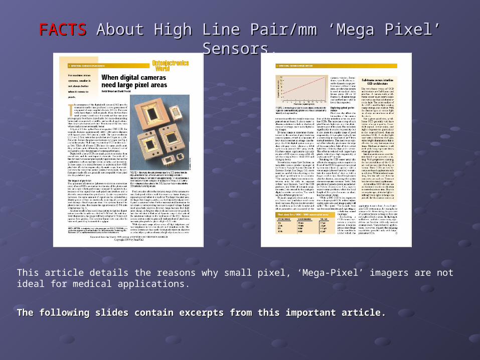
FACTSFACTS About High Line Pair/mm ‘Mega Pixel’ About High Line Pair/mm ‘Mega Pixel’ Sensors.Sensors.
This article details the reasons why small pixel, ‘Mega-Pixel’ imagers are not ideal for medical applications.
The following slides contain excerpts from this important article.The following slides contain excerpts from this important article.

FACTSFACTS About High Line Pair/mm About High Line Pair/mm ‘Mega Pixel’ Sensors.‘Mega Pixel’ Sensors.
1.1. ……the consumer market has produced a new generation of mega-the consumer market has produced a new generation of mega-pixel CCDs. But even with more than a million pixels, these pixel CCDs. But even with more than a million pixels, these devices have small physical pixels areas that…have drawbacks devices have small physical pixels areas that…have drawbacks for more demanding industrial, scientific, and medical for more demanding industrial, scientific, and medical applications. Here, applications. Here, larger pixel areas are betterlarger pixel areas are better..
2.2. Responsivity is a measure of the signal that each pixel can Responsivity is a measure of the signal that each pixel can produce and is directly proportional to pixel area. As responsivity produce and is directly proportional to pixel area. As responsivity increases, the same amount of signal can be collected in a increases, the same amount of signal can be collected in a shorter period of time. Or…more signal can be realized during a shorter period of time. Or…more signal can be realized during a fixed exposure time.fixed exposure time.
Article Excerpts:

FACTSFACTS About High Line Pair/mm About High Line Pair/mm ‘Mega Pixel’ Sensors.‘Mega Pixel’ Sensors.
3.3. Another benefit of increased responsivity is… the image will have Another benefit of increased responsivity is… the image will have a higher signal/noise ratio and appear less grainy.a higher signal/noise ratio and appear less grainy.
4.4. Pixel [size] also affects the dynamic range of the [system]. Each Pixel [size] also affects the dynamic range of the [system]. Each pixel is like a well that stores up [data] before it is read out. The pixel is like a well that stores up [data] before it is read out. The larger the pixel area, the larger the [data] capacity, and the larger the pixel area, the larger the [data] capacity, and the higher the signal level.higher the signal level.
5.5. …dynamic range allows areas of high brightness and low …dynamic range allows areas of high brightness and low brightness to be seen clearly and simultaneously… [and] thus brightness to be seen clearly and simultaneously… [and] thus easily distinguish objects in shadows. It is also easier to discern easily distinguish objects in shadows. It is also easier to discern variations in dark or shadowed areas of an image, such as in variations in dark or shadowed areas of an image, such as in digital x-ray images.digital x-ray images.
Article Excerpts:
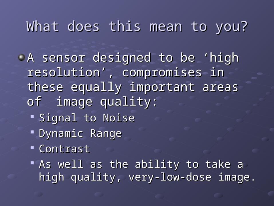
What does this mean to you?What does this mean to you?
A sensor designed to be ‘high resolution’, A sensor designed to be ‘high resolution’, compromises in these equally important compromises in these equally important areas of image quality:areas of image quality: Signal to Noise Signal to Noise Dynamic RangeDynamic Range ContrastContrast As well as the ability to take a high quality, As well as the ability to take a high quality,
very-low-dose image.very-low-dose image.

Signal to Noise RatioSignal to Noise Ratio
‘‘Noise’ can be defined as any image data that is not Noise’ can be defined as any image data that is not 100% accurate.100% accurate.
By contrast, ‘signal’ is image data that accurately By contrast, ‘signal’ is image data that accurately represents the image.represents the image.
‘‘Noise’ makes the image look grainyNoise’ makes the image look grainy

Signal to Noise RatioSignal to Noise Ratio
‘‘FACT: High lp/mm sensors have poorer signal to noise FACT: High lp/mm sensors have poorer signal to noise ratio due to their small pixel size. This results in ratio due to their small pixel size. This results in GRAINIER IMAGESGRAINIER IMAGES
The noise created by smaller pixels most likely The noise created by smaller pixels most likely eliminates any advantage created by the increase in eliminates any advantage created by the increase in spatial resolution.spatial resolution.

Signal to Noise RatioSignal to Noise Ratio
Most digital radiography systems offer a wide range of Most digital radiography systems offer a wide range of noise filtering software as part of their tool set.noise filtering software as part of their tool set.
These ‘filters’ can not compensate for poor original image data These ‘filters’ can not compensate for poor original image data coming from the pixels on the sensor.coming from the pixels on the sensor.
Many of these filter actually create artifacts of their own.Many of these filter actually create artifacts of their own. GIGO = Garbage in, Garbage out.GIGO = Garbage in, Garbage out.
For this reason - when evaluating/comparing digital For this reason - when evaluating/comparing digital systems – it important to make sure any software filters systems – it important to make sure any software filters are turned OFF.are turned OFF.

Signal to Noise RatioSignal to Noise RatioHere is an image with no ‘enhancements’ or software filters.
Note how easy it is to see distinct line pairs all the way to the bottom of the image.

Signal to Noise RatioSignal to Noise Ratio
Here is a close-up of the same image with the software filter enhancements turned ‘ON’
Note how much worse the lp/mm rating becomes.

Always evaluate image quality with ALL Always evaluate image quality with ALL software filters ‘OFF’software filters ‘OFF’
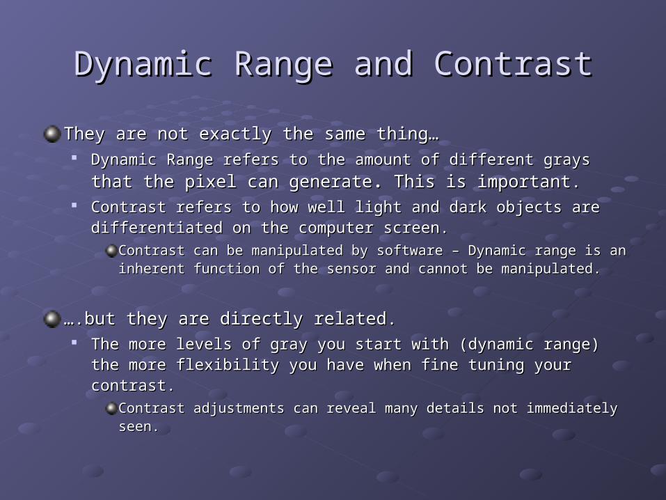
Dynamic Range and ContrastDynamic Range and Contrast
They are not exactly the same thing…They are not exactly the same thing… Dynamic Range refers to the amount of different grays Dynamic Range refers to the amount of different grays that the pixel that the pixel
can generatecan generate.. This is important. This is important. Contrast refers to how well light and dark objects are differentiated on Contrast refers to how well light and dark objects are differentiated on
the computer screen. the computer screen.
Contrast can be manipulated by software – Dynamic range is an inherent Contrast can be manipulated by software – Dynamic range is an inherent function of the sensor and cannot be manipulated.function of the sensor and cannot be manipulated.
…….but they are directly related..but they are directly related. The more levels of gray you start with (dynamic range) the more The more levels of gray you start with (dynamic range) the more
flexibility you have when fine tuning your contrast.flexibility you have when fine tuning your contrast.
Contrast adjustments can reveal many details not immediately seen.Contrast adjustments can reveal many details not immediately seen.

Dynamic Range and ContrastDynamic Range and Contrast
Dynamic range is expressed in ‘bits’Dynamic range is expressed in ‘bits’ 8 bit = 256 levels of gray8 bit = 256 levels of gray 10 bit = 1024 levels of gray10 bit = 1024 levels of gray 12 bit = 4096 levels of gray12 bit = 4096 levels of gray
A common trick of manufacturers is to quote the dynamic A common trick of manufacturers is to quote the dynamic range of the analog-to-digital converter (ADC) range of the analog-to-digital converter (ADC)
The ADC is the microchip that takes the pixel output and The ADC is the microchip that takes the pixel output and converts it to a digital signal). converts it to a digital signal).
The ADC very often can support a MUCH higher dynamic range The ADC very often can support a MUCH higher dynamic range than the output of the sensor pixels. than the output of the sensor pixels.
Though the high dynamic range of the ADC may sound Though the high dynamic range of the ADC may sound impressive, it does absolutely zero for image quality if it the impressive, it does absolutely zero for image quality if it the pixels cannot support it.pixels cannot support it.
Larger Pixels = lower lp/mm = BETTER DYNAMIC Larger Pixels = lower lp/mm = BETTER DYNAMIC RANGERANGE
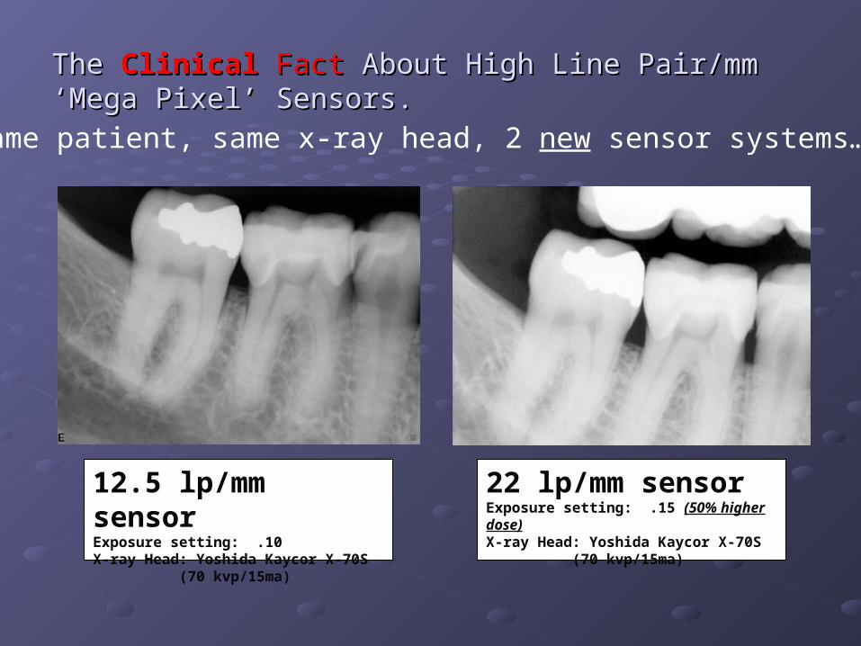
The The ClinicalClinical FactFact About High Line Pair/mm ‘Mega About High Line Pair/mm ‘Mega Pixel’ Sensors.Pixel’ Sensors.
12.5 lp/mm sensor
Exposure setting: .10 X-ray Head: Yoshida Kaycor X-70S
(70 kvp/15ma)
Same patient, same x-ray head, 2 new sensor systems…
22 lp/mm sensor Exposure setting: .15 (50% higher dose)X-ray Head: Yoshida Kaycor X-70S
(70 kvp/15ma)

What have we learned about What have we learned about specifications?specifications?
1.1. They are confusing – and don’t always They are confusing – and don’t always mean what you think they mean.mean what you think they mean.
2.2. Some manufacturers use them to Some manufacturers use them to mislead potential buyers.mislead potential buyers.
3.3. Don’t use them as a basis to judge Don’t use them as a basis to judge image quality.image quality.

Part Three - How to Choose a Part Three - How to Choose a SystemSystem
1.1. Take some x-rays in your office BEFORE Take some x-rays in your office BEFORE you make any commitment.you make any commitment.
2.2. Only use the x-rays that YOU take to Only use the x-rays that YOU take to evaluate the system’s image quality.evaluate the system’s image quality.
3.3. Take a variety of images on a live Take a variety of images on a live volunteer.volunteer.
Take some x-rays in your office Take some x-rays in your office BEFORE you make ANY BEFORE you make ANY
commitment.commitment.
Live images ensure the system will work Live images ensure the system will work with your existing equipment x-ray heads.with your existing equipment x-ray heads. A sales rep or experienced user should be A sales rep or experienced user should be
present show you how to operate the system.present show you how to operate the system.

Only use the x-rays that YOU take to Only use the x-rays that YOU take to evaluate the system’s image quality.evaluate the system’s image quality.
All companies have a set of ‘perfect All companies have a set of ‘perfect images’ they use during sales images’ they use during sales presentations.presentations. These are not ‘typical clinical images’These are not ‘typical clinical images’ The history of these images is unknown.The history of these images is unknown.
Exposure setting?Exposure setting?
What type x-ray head?What type x-ray head?
Cadaver or live patient?Cadaver or live patient?
Modified?Modified?

Take a variety of images on a live Take a variety of images on a live volunteer.volunteer.
This is critical. By actually taking images on This is critical. By actually taking images on yourself or a staff member, you’ll answer yourself or a staff member, you’ll answer questions you may not even know to ask;questions you may not even know to ask; Can it take vertical bitewings?Can it take vertical bitewings? Is the sensor to big/small?Is the sensor to big/small? Do the positioners work?Do the positioners work? Is it comfortable?Is it comfortable? Is there some other operating ‘issue’ – such as a Is there some other operating ‘issue’ – such as a
remote button to push – that is unwieldy?remote button to push – that is unwieldy?

Evaluating Digital Systems – Evaluating Digital Systems – Image QualityImage Quality
Resize all images to fill the screen before evaluation.Resize all images to fill the screen before evaluation. This is how you’ll most often view.This is how you’ll most often view. Some systems have the original image come up very small. This Some systems have the original image come up very small. This
can hide image defects.can hide image defects.
No enhancementsNo enhancements Turn off all software filters. They can make a poor image look Turn off all software filters. They can make a poor image look
good at first glance.good at first glance. Diagnostic quality is only as good as the original, raw image.Diagnostic quality is only as good as the original, raw image.
Check Exposure SettingsCheck Exposure Settings Ensure images to be evaluated are properly exposed.Ensure images to be evaluated are properly exposed. Check the exposure setting; it should be much lower than what Check the exposure setting; it should be much lower than what
you now use for film.you now use for film.

Evaluating Digital Systems – Evaluating Digital Systems – UsabilityUsability
Vertical BitewingsVertical Bitewings Not all systems can take a vertical bitewing. If this is important to Not all systems can take a vertical bitewing. If this is important to
you, make sure you try taking some during the live demo.you, make sure you try taking some during the live demo.
BitewingsBitewings The most common intraoral image.The most common intraoral image. How many teeth are captured with each image? Are you getting How many teeth are captured with each image? Are you getting
as many with the size 2 sensor as you would with size 2 film?as many with the size 2 sensor as you would with size 2 film?
PediatricPediatric Does the system have a solution for small mouths?Does the system have a solution for small mouths?

Evaluating Digital Systems – Evaluating Digital Systems – SoftwareSoftware
Auto-template AdvanceAuto-template Advance When taking multiple images (e.g. FMX series) you shouldn’t When taking multiple images (e.g. FMX series) you shouldn’t
have to reset the system – keystroke, button, etc - in any way have to reset the system – keystroke, button, etc - in any way between images.between images.
RetakesRetakes This common task should be automated so it’s quick and easy.This common task should be automated so it’s quick and easy.
Auto-saveAuto-save Each image should be saved immediately and automatically Each image should be saved immediately and automatically
upon acquisition. Individual saving of each image is tedious and upon acquisition. Individual saving of each image is tedious and may lead to accidentally deleted imagesmay lead to accidentally deleted images
Evaluating Digital Systems – Evaluating Digital Systems – SoftwareSoftware
Image file typeImage file type All images should be saved in a non-proprietary file All images should be saved in a non-proprietary file
format, without the need for conversion. This allows format, without the need for conversion. This allows you great flexibility for sharing and future expansion.you great flexibility for sharing and future expansion.
Viewable image size upon captureViewable image size upon capture Does the image appear in full screen mode Does the image appear in full screen mode
automatically? automatically? This is esp. valuable when taking more than one This is esp. valuable when taking more than one
image – it allows the operator to quickly check image – it allows the operator to quickly check positioning/exposure/etc. from across the room if positioning/exposure/etc. from across the room if needed.needed.

Evaluating Digital Systems – Evaluating Digital Systems – WarrantyWarranty
Compare all costs for at least 5 years, assuming 2 Compare all costs for at least 5 years, assuming 2 sensor replacements per yearsensor replacements per year
What is covered?What is covered? What is the companies policy on accidental damage?What is the companies policy on accidental damage?
Replacement costReplacement cost What are the costs associated with sensors under the ongoing What are the costs associated with sensors under the ongoing
service plan (the post-warranty period)?service plan (the post-warranty period)?
Replacement turnaround time.Replacement turnaround time. What is the quoted turnaround time on replacements?What is the quoted turnaround time on replacements? Is this guaranteed?Is this guaranteed? Can it be confirmed by referrals?Can it be confirmed by referrals?

Evaluating Digital Systems – Evaluating Digital Systems – ServiceService
800# Tech Support800# Tech Support Call during the demo. How long does it take to get a tech on the line?Call during the demo. How long does it take to get a tech on the line?
Local Installer/ Service TechnicianLocal Installer/ Service Technician Who is it and where are they located?Who is it and where are they located? Are they a direct employee of the company selling the sensor?Are they a direct employee of the company selling the sensor? What is the typical wait time for a service call? Can it be verified by What is the typical wait time for a service call? Can it be verified by
referral?referral?
Routine VisitsRoutine Visits Will a representative of the company be willing and able to visit your Will a representative of the company be willing and able to visit your
office regularly, after the sale is complete, if desired?office regularly, after the sale is complete, if desired?
What if you’re not happy with the sale?What if you’re not happy with the sale? Does the company have any satisfaction guarantee in writing?Does the company have any satisfaction guarantee in writing? What is the return policy if you are not satisfied?What is the return policy if you are not satisfied?

Evaluating Digital Systems – Evaluating Digital Systems – ReferencesReferences
Are they local?Are they local?
How long have they had the system? How long have they had the system?
What do they like/dislike about the What do they like/dislike about the system?system?

Evaluating Digital Systems – Evaluating Digital Systems – PricePrice
““Cheap things are seldom good, and good things are seldom cheap” – Cheap things are seldom good, and good things are seldom cheap” – Zig ZiglarZig Ziglar
No other dental technology saves you moneyNo other dental technology saves you money – by – by
eliminating films – eliminating films – at the same time it makes you moneyat the same time it makes you money – – by increasing productivity.by increasing productivity.
Digital radiography is a no lose financial proposition, assuming:Digital radiography is a no lose financial proposition, assuming: You buy everything you need to go film-lessYou buy everything you need to go film-less Don’t cut corners – spend a little more to get high quality Don’t cut corners – spend a little more to get high quality
equipment/service equipment/service Use it everyday, on every patientUse it everyday, on every patient

Evaluating Digital Systems – Evaluating Digital Systems – PricePrice
How much can you afford to spend? How much can you afford to spend?
Step 1 - Take what you spent on film, processing chemicals, processor Step 1 - Take what you spent on film, processing chemicals, processor maintenance last year.maintenance last year.
Step 2 - Multiply the number of films you took last year and increase Step 2 - Multiply the number of films you took last year and increase your fee by $1 each.your fee by $1 each.
Step 3 - Add the above two $ numbers together and divide by 12.Step 3 - Add the above two $ numbers together and divide by 12.
You now have the amount you can spend on a monthly lease payment, You now have the amount you can spend on a monthly lease payment, without costing you a pennywithout costing you a penny more than what you already are more than what you already are spending!spending!

Why Go Digital?Why Go Digital?
EfficiencyEfficiency
Patient CommunicationPatient Communication
ALARAALARA
Reduction of overheadReduction of overhead
Practice Marketing/New Patient referralsPractice Marketing/New Patient referrals
ConsistencyConsistency

DownloadsDownloads
Download a checklist that outlines the digital radiography Download a checklist that outlines the digital radiography evaluation process covered in this presentation.evaluation process covered in this presentation.
Click hereClick here
Download other documents referenced in this Download other documents referenced in this presentation from the internet.presentation from the internet.
UMKC study – Durability of Phosphor PlatesUMKC study – Durability of Phosphor Plateshttp://www.thejcdp.com/issue018/index.htmhttp://www.thejcdp.com/issue018/index.htm
Optoelectronics World – The Need for Large PixelsOptoelectronics World – The Need for Large Pixelshttp://www.kodak.com/US/en/digital/pdf/largePixels.pdfhttp://www.kodak.com/US/en/digital/pdf/largePixels.pdf
Dr. AG Farman - Digital Radiography ’04Dr. AG Farman - Digital Radiography ’04http://www.aadmrt.com/static.aspx?content=currents/farman_spring_04http://www.aadmrt.com/static.aspx?content=currents/farman_spring_04

About the AuthorAbout the Author
Walter Golub, DMDWalter Golub, DMD1962 Rutgers University1966 Tufts University School of Dental Medicine1966-68 US Air Force Active Duty1968-70 Full-time Faculty -Tufts 1970-91 Private Practice of Dentistry (3 locations)1989-1994 Co-Developer of the Victor Voice Chart; 2001-2003 Discus Dental Software-National Sales Mgr. 2003-present Schick Technologies Director of Clinical Affairs
Dr. Golub has traversed the dental landscape. His career includes teaching, private practice, software development, writer and lecturer.
In his younger days, he was heavily involved in rugby both playing and coaching, and he has served as a small town school board member and a justice of the peace.
He is not licensed to perform marriages in Canada.