digital power meter user manual dpm380 - itmikro.com · b) insert the power meter through the hole...
TRANSCRIPT

Digital Power Meter User ManualDPM380
No.1, Jalan TP7/7, Sime UEP Industrial Park,40400 Shah Alam, Selangor, Malaysia. Website: www.itmikro.com Tel: +(603)51927155 Fax: +(603)51927166
v1.0

HAZARD CATAGORIES AND SPECIAL SYMBOL
Read all instruction carefully and check the device before installing or service it. The following safety alert symbol may appear throughout this manual or on device to warn any potential hazards or to call for attention.
PLEASE NOTEThe power meter should be installed, operated, serviced and maintained only by qualifi ed personnel. No responsibility is assumed by the manufacturer for any consequences arising out of the use of this material.
DISCLAIMERMikro shall not be liable for errors contained herein including any incidential and/or consequential damages arising from the use of this material. Mikro also reserves the right to vary the product from that described in this material without prior notice.
COPYRIGHTThe licensed software contaioned in the product is proprietary software owned by Mikro or its third party suppliers and shall be used solely in connection with the product.

BEFORE YOU BEGIN• Apply appropriate personal protective equipment and
follow safe electrical work practices. • NEVER work alone.• Turn-off all power supplying the power meter and the
equipment in which it is installed before working on it.• Always use a properly rated voltage sensing device to
confi rm that all power is off .• Before closing all covers and doors, carefully inspect the
work area for tools and objects that may have been left inside the equipment.
• NEVER bypass external fusing.• NEVER open circuit a CT; use the shorting block to short
circuit the leads of the CT before removing the connec-tion from the power meter.
• Before performing hi-pot testing on any equipment in which the power meter is installed, disconnect all input and output wires to the power meter. High voltage test-ing may damage electronic components contained in the power meter.
• The power meter should be installed in a suitable electri-cal enclosure.
Failure to follow this instruction may result in serious injury.

CONTENTS
1. Introduction 1.1.Content of box 1.2.Part of power meter
2. Installation Guide 2.1.Precautions 2.2.Mounting 2.3. Wiring
3. Meter parameters
4. Display and Buttons
5. Function
6. Setting up 6.1.Access programming mode 6.2.Setup CT ratio 6.3.Setup PT ratio 6.4.Neutral current 6.5.Setup communication confi guration 6.6.Demand setting 6.7.System setting 6.8. Reset all energy register 6.9. Reset demand register 6.10. Reset maximum & minimum value 6.11. Remote set 6.12. Scroll mode setting
112
4447
11
12
13
15151617181920212223242526

6.13. Scroll delay setting 6.14. Reset Hour on register 6.15. Backlight setting 6.16. Exit from programming mode 6.17. Setup new password
7. Specifi cations
8. Modbus table
9. Maintenance and troubleshooting
10. Dimensions
11. Appendix 11.1. Demand calculation 11.2. Data read format from modbus
2728293031
33
36
50
51
535354

FIGURES
1. Parts of power meter2. Recommendation cut-out3. 3-phase 4-wire system with 4 CTs4. 3-phase 4-wire system with 3 CTs5. 3-phase 3-wire with 3CTs and 3VTs6. 3-phase 3-wire with 2CTs and 3VTs7. Menu map for the normal mode8. Flow map for the programming mode
24789
101314
TABLE
1. Parts list2. Location and part label3. Model information4. Specifi cation5. Data length nomenclature6. Device and communication register7. Operation data registers8. Setting data registers
123
3336373749

Thank you for purchasing the DPM380 Digital Power Meter. This multifunction power meter measuring the following parameters:
• True RMS phase voltage ( L-N )• True RMS line voltage (L-L )• True RMS phase and neutral current• Active, reactive and apparent power• Total active, reactive and apparent energy• Total and displacement power factor• Frequency• Voltage and current total harmonic distortion (THD)• Demand and maximum demand for total active, reactive
and apparent power• Maximum and minimum phase and line voltage• Maximum and minimum phase and neutral current• Maximum and minimum total active, reactive ad appar-
ent power
1.2. CONTENT OF BOXUpon opening this box, you should fi nd the following item shown in table 1:
No Description Quantity1 DPM380 power meter 1
2 Retainer clip 23 Quick guide 1
Table 1 : Parts list
1.Introduction

2
5
1 2
34
1 2 3 4 57 8
14131211109
L1
+-
100V~300VDC90V~415VAC
201918171615
6
L2 L3 Ln
Gnd +-
Modbus RTU RS485
I1 I2 I3 In
S1S1S1S1 S2 S2 S2 S2
CURRENT INPUTS ... / 5A (6A MAX.)
3VA
AUX
50/60HzVOLTAGE INPUT L-N 300V MAX. 50/60HzCategory III
56
6
Number Part Description1 Current inputs Current metering connec-
tions.2 RS485 port The RS485 port is used for
communication with remote monitoring and control system.
3 Power supply input
Connection to power the meter
4 Voltage inputs Voltage metering connec-tions.
5 Retainer clips Used to hold power meter in place.
6 Retainer clips slot
To slot in retainer clips in place
Table 2: Location and part label
1.3. PARTS OF POWER METER
Figure 1 : Parts of power meter

3
Model InformationDPM380-415AD Auxiliary 90~415VAC or
100~300VDC; with Modbus
Table 3: Model information

4
2.2. MOUNTINGa) Provide a cut out hole on the switchgear panel according to the dimension below.
Figure 2:Recommended out-cut.
91
0.5m
m
91 0.5mm
2. Installation Guide
Before installing the power meter,please check that the environment meets the following condition:
• Operating temperature -10 Celcius to +55 Celcius.• Humidity 5% to 95%, non-condensing• Dust free environmental away from electrical noise and
radiation
2.1. PRECAUTIONS

5
b) Insert the power meter through the hole and slide in the retainer clip along the slots on left and right sides or bottom and top sides of the power meter until the device is tightly secured on the switchgear panel. The orientation of the retainer clips is shown in fi gure 1.
The retainer clip can be removed by lifting the tab lightly at the handle end.
c) Connect the metering voltage input, current input, communcation and auxiliary according to the wiring schemes shown in section 2.2 fi gure 3 to 6 on the next page.
d) The recomended wire size is as below:
• voltage input and auxiliary - AWG16~22• current input - AWG12~18• Modbus-RTU - AWG22 or thicker, shielded twisted pair
NOTE: Polarity marks must be followed as shown for CTs (S1 and S2).
Please make sure the power to the current meter-ing input is totally shunted. Under no circumstances can the CT connection be left open circuit. Use a CT shorting block if necessary.

6
e) When connecting the power meter, please make sure the polarity to the terminal is correctly aligned.
f) If the Modbus-RTU is used, it can be connected up to 32 devices in a daisy chain fashion and the cable total length should not be more than 1000m.
NOTE: For Modbus-RTU connection, avoid running the cable near sources of electrical noise. The network cable sheild should be grounded at only one end.

7
Figure 3: 3 Phase 4-Wire System with 4CTs connection, direct voltage input.
2.3. WIRING
19
201234
567
8
15
16
17
18
14
13
12

8
Figure 4: 3-Phase 4-Wire System with 3CTs connection, direct voltage input.
NOTE: Neutral current measurement is based on the vector sum of 3 CTs.
19
201234
567
8
15
16
17
18
14
13
12

9
Figure 5: 3-phase 3-wire with 3CTs and 3VTs connection.
19
201234
56
7
8
15
16
17
18
14
13
12

10
Figure 6: 3-phase 3-wire with 2CTs and 3VTs connection.
NOTE: I2 current measurement is based on the vector sum of 2 CTs.
19
201234
56
78
15
16
17
18
14
13
12

11
3. Meter parameters
Before commencing operation, the meter has to be set up. To do this, the meter must be powered up by the meter control power supply.
Under section 6, the following parameters should be reviewed against the default value if necessary:
• CT ratio• PT ratio• Neutral current input• Modbus-RTU setting• Demand setting• System setting • Scroll mode setting and delay time• Backlight setting
The fl ow maps for the meter is under section 5. It is guideline for the user to fl ip to the desire window whether in normal mode or programming mode.
12
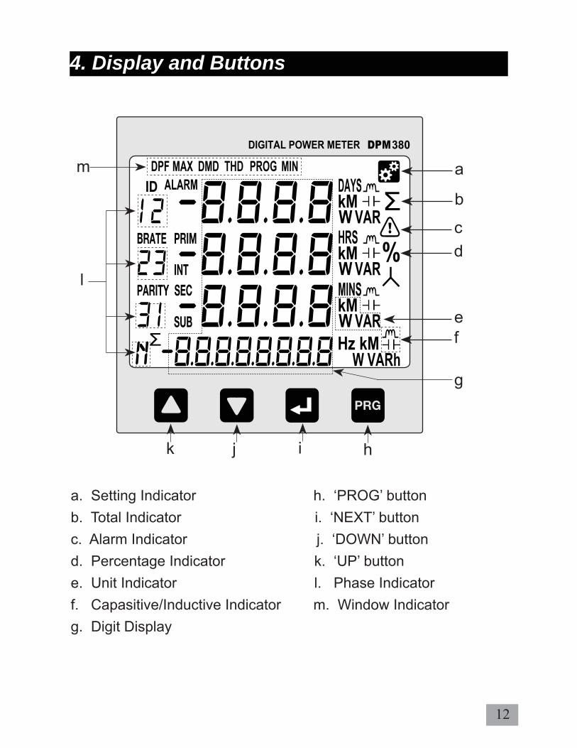
a. Setting Indicator h. ‘PROG’ buttonb. Total Indicator i. ‘NEXT’ buttonc. Alarm Indicator j. ‘DOWN’ buttond. Percentage Indicator k. ‘UP’ buttone. Unit Indicator l. Phase Indicatorf. Capasitive/Inductive Indicator m. Window Indicatorg. Digit Display
4. Display and Buttons
a
b
cd
ef
g
hijk
l
m

13
Figure 7 below shows menu map for the power meter. It includes the setting and measurement display for the power meter. These menus can be accessed by pressing NEXT, UP, PROG & DOWN buttons.
Figure 7 : Menu map for normal mode.
5. Function
Line Current (A) Current Min. (A)
Current Max. (A)
Line Voltage (V) PhaseVoltage (V)
Min. LineVoltage(V)
Min. PhaseVoltage(V)
Max. LineVoltage(V)
Max. Phase Voltage(V)
Power factor(PF) & Frequency(Hz)
True Power factor(PF)
Displacement Power Factor (DPF)
Total Power(W, VAR, VA)
Min. Real Power (W)
Min. Total Power (W,VAR, VA)
Demand (W,VAR,VA)
Max. Demand (W,VAR,VA)
Total RealEnergy (Wh)
Total Neg.Real Energy (-kWh)
Total Reactive Energy (VARh)
THD Current (A)
THD Voltage (V)
Hour On(Days, Hrs, Mins)
Real Power(W)
Reactive Power(VAR)
Apparent Power(VA)
Max. Real Power (W)
Max. Total Power (W,VAR, VA)
Min. Reactive Power (VAR)
Max. Reactive Power (VAR)
Min. ApparentPower (VA)
Max. Apparent Power (VA)
Total Neg. Reac. Energy (-VARh)
Total Apparent Energy (VAh)

14Figure 8 : Menu map for programming mode
PROG Mode
CT Ratio Setting (A)
To change value range 5 - 9999A for primary and 5A for secondary
PT Ratio Setting (V)
To change value range 100 - 33kV for primary and 100 -120V for secondary
Neutral Current Setting (Ln)
Reset All Energy Regsiter
Reset (Yes/No)
Reset Demand Register
Reset (Yes/No)
Scroll Display Setting
To scroll display in idle mode (ON/OFF)
Demand Setting
Remote Set
Reset Max/Min
Reset (Yes/No)
System Setting
Scroll DelayTime
To set interval time for scroll display (1-10secs)
Reset Hour-On Register
Reset (Yes/No)
Backlight Setting

15
The power meter comes with factory default settings. These values may be changed by navigating to the appropriate screens and entering new values. Use the instructions in the following sections to change the values.
a. Press the PROG button to enter programming mode. The fi rst number will blink to enter password.
b. Use the UP or DOWN button to change display value and the NEXT button to shift to next number.
c. Press the PROG button to confi rm and enter programming mode. Setup CT ratio will be display. If the password is incorrect, the meter will return to normal mode.
d. To exit press the PROG button and display will return to normal mode.
6.1. ACCESS PROGRAMMING MODE
6. Setting up
NOTE: Default password is “0000”

16
a. CT ratio setting is the fi rst item display in programming mode.
b. Press the NEXT button to change. The fi rst digit will blink.
c. Use the UP or DOWN button to change the primary CT value.
d. Press the NEXT button for the next digit. Repeat step (b) & (c) to change, or else press NEXT button till the digit stop blinking.
e. To proceed next setting press DOWN button. To exit programming mode, press the PROG button. The user will be prompted to confi rm the saving of settings if change is made. Refer section 6.16.
6.2. SETUP CT RATIO
NOTE: CT ratio default value is 5/5A

17
a. Scroll in programming mode until ”Pt“ is displayed using the UP or DOWN button.
b. This parameter is to change the PT value if the Power Transformer (PT) is connected.
c. Press the NEXT button to change. The “V” symbol for primary will blink.
d. Press the UP or DOWN button to change the value of setting.
e. Press the NEXT button to confi rm the new setting and proceed for secondary setting.
f. Repeat step (c) & (d) to change for secondary. Once confi rm, press the NEXT button again to confi rm. The secondary “V” will stop blinking.
g. To exit programming mode, press the PROG button. Refer section 6.16.
6.3. SETUP PT RATIO
NOTE: PT ratio default value is 100/100V

18
a. Scroll in programming mode until ”Ln“ is displayed using the UP or DOWN button.
b. This parameter is to display neutral current if the neutral current (Ln) is connected.
c. Press the NEXT button to change. The “PROG” symbol will blink.
d. Press the UP or DOWN button to toggle the symbol “ON” for enable or “OFF” for disable.
e. Press the NEXT button to confi rm the new setting.
f. To proceed to the next setting, press the DOWN button.
g. To exit programming mode, press the PROG button. The user will be prompted to confi rm the saving of settings if change is made. Refer section 6.16.
6.4. NEUTRAL CURRENT
NOTE: Neutral current default value is ON

19NOTE: Default value for the communication ID is 0001, baudrate is 38400 bps and parity set to none.
6.5. SETUP COMMUNICATION CONFIGURATIONS
a. Scroll until ”ID BRATE PARITY“ is displayed using the UP or DOWN button.
b. Press the NEXT button. The “PROG” and “-” symbol next to “ID” will blink. Use the UP or DOWN button to change the device ID.
c. Next, press the NEXT button and “-”symbol next to “BRATE” will blink to change baudrate. Repeat step (b) to change.
d. Press NEXT button to change parity and “-” symbol next to “PARITY” will blink. Repeat step (b) to change.
e. Then press the NEXT button to confi rm new setting. The “PROG” will stop blinking.
f. To proceed next setting press DOWN button. To exit programming mode, press the PROG button. The user will be prompted to confi rm the saving of settings if change is made. Refer section 6.16.

20
6.6. DEMAND SETTING
a. Scroll until ”DMD“ is displayed using the UP or DOWN button.
b. Press the NEXT button to change interval value. The “PROG” symbol will displayed and “-”symbol next to “INT” will blink.
c. Use UP or DOWN button to change value and press NEXT button to confi rm and change sub-interval setting. The “-” symbol next to “SUB” will blink. Press UP or DOWN button to change and NEXT button to confi rm.
d. To proceed next setting press DOWN button. To exit programming mode, press the PROG button. The user will be prompted to confi rm the saving of settings if change is made. Refer section 6.16.
NOTE: Demand setting default value is 60/4

21
6.7. SYSTEM SETTING
a. Scroll in programming mode until ”SYSt sEt“ is displayed using the UP or the DOWN button.
b. Press the NEXT button. The “PROG” symbol will blink. Use the UP or DOWN button to toggle 3-phase 4-wire “3P4r” or 3-phase 3-wire “3P3r” symbols.
c. Press the NEXT button to confi rm new setting.
d. To proceed next setting press DOWN button. To exit programming mode, press the PROG button. The user will be prompted to confi rm the saving of settings if change is made. Refer section 6.16.
NOTE: System setting default value is 3-phase 4-wire

22
6.8. RESET ALL ENERGY REGISTER
a. Scroll in programming mode until ”EnEr rSEt“ is displayed using the UP or the DOWN button.
b. Press the NEXT button. The “PROG” symbol will blink. Use the UP or DOWN button to toggle “YES” or “NO” symbols.
c. To abort clearing energy register values, select “NO”. To clear all energy values select “YES”.
d. Press the NEXT button to confi rm the new setting.
e. To proceed next setting press DOWN button.
f. To exit programming mode, press the PROG button. The user will be prompted to confi rm the saving of settings if change is made. Refer section 6.16.

23
6.9. RESET DEMAND REGISTER
a. Scroll in programming mode until ”dMd rSt“ is displayed using the UP or the DOWN button.
b. Press the NEXT button. The “PROG” symbol will blink. Use the UP or DOWN button to toggle “YES” or “NO” symbols.
c. To abort clearing demand register, select “NO”. To clear all demand register select “YES”.
d. Press the NEXT button to confi rm the new setting.
e. To proceed next setting, press DOWN button.
f. To exit programming mode, press the PROG button. The user will be prompted to confi rm the saving of settings if change is made. Refer section 6.16.

24
6.10. RESET MAXIMUM AND MINIMUM VALUE
a. Scroll until ”rSEt“ is displayed using the UP or the DOWN button.
b. Press the NEXT button. The “PROG” symbol will blink. Use the UP or DOWN button to toggle “YES” or “NO” symbols.
c. To abort clearing max. and min. values, select “NO”. To clear all max. and min. values select “YES”.
d. Press the NEXT button to confi rm new setting.
e. To proceed next setting press DOWN button.To exit programming mode, press the PROG button. The user will be prompted to confi rm the saving of settings if change is made. Refer section 6.16.

25
NOTE: Enabling the remote set allows the remote terminal to read and write the meter setting via Modbus-RTU, otherwise the setting data can only be read. Default value is ON.
6.11. REMOTE SET
a. Scroll until ”rMt SEt“ is displayed using the UP or the DOWN button.
b. Press the NEXT button. The “PROG” symbol will blink. Use the UP or DOWN button to toggle Enable “ON” or disable “OFF” symbols.
c. Press the NEXT button to confi rm new setting.
d. To proceed next setting press DOWN button. To exit programming mode, press the PROG button. The user will be prompted to confi rm the saving of settings if change is made. Refer section 6.16.

26
6.12. SCROLL SETTING
a. Scroll in programming mode until ”Scrl SEt“ is displayed using the UP or the DOWN button.
b. This function is to turn ON/OFF scroll mode. If turn on, when the display is idle the meter will shows each window in normal mode base on the scroll delay setting time.
c. Press the NEXT button. The “PROG” symbol will blink. Use the UP or DOWN button to toggle “OFF” or “ON” symbols.
d. Press the NEXT button to confi rm the new setting.
e. To proceed next setting, press DOWN button.
f. To exit programming mode, press the PROG button. The user will be prompted to confi rm the saving of settings if change is made. Refer section 6.16.
NOTE: Scroll setting default value is OFF

27
6.13. SCROLL DELAY SETTING
a. Scroll in programming mode until ”Scrl dELY“ is displayed using the UP or the DOWN button.
b. This function is to set time interval for scroll window.
c. Press the NEXT button. The “PROG” symbol will blink. Use the UP or DOWN button to set 1sec to 10secs interval.
d. Press the NEXT button to confi rm the new setting.
e. To proceed next setting, press DOWN button.
f. To exit programming mode, press the PROG button. The user will be prompted to confi rm the saving of settings if change is made. Refer section 6.16.
NOTE: Scroll delay time default value is 10 seconds.

28
6.14. RESET HOUR-ON REGISTER
a. Scroll in programming mode until ”Hron rSt“ is displayed using the UP or the DOWN button.
b. This function is to clear hour-on register.
c. Press the NEXT button. The “PROG” symbol will blink. Use the UP or DOWN button to toggle “YES” or “NO” symbols.
d. To abort clearing hour-on register, select “NO”. To clear hour-on register select “YES”.
e. Press the NEXT button to confi rm the new setting.
f. To proceed next setting, press DOWN button.
g. To exit programming mode, press the PROG button. The user will be prompted to confi rm the saving of settings if change is made. Refer section 6.16.

29
6.15. BACKLIGHT SETTING
a. Scroll in programming mode until ”bcLt“ is displayed using the UP or the DOWN button.
b. This function is to turn off backlight after 10minutes idle.
c. Press the NEXT button. The “PROG” symbol will blink. Use the UP or DOWN button to toggle “OFF” or “ON” symbols.
d. Press the NEXT button to confi rm the new setting.
e. To proceed next setting, press DOWN button.
f. To exit programming mode, press the PROG button. The user will be prompted to confi rm the saving of settings if change is made. Refer section 6.16.
NOTE: Backlight setting default value is OFF

30
6.16. EXIT FROM PROGRAMMING MODE
a. Use the PROG button exit from programming mode window. Any changes made in the setting will be prompted to confi rm saving. The “SAVE SET” display will appear.
b. Use the UP or DOWN button to select “YES” or “NO” symbols.
c. To exit without saving the new value, select “NO” or else select “YES”. To confi rm, press PROG button.
d. If select “YES”, the window display “SAVE” for few seconds to save new setting.
e. Then, meter will exit from programing mode to normal mode.
If select “Yes”

31
a. Press the NEXT and PROG buttons simultaneously until the password ID request window is displayed. Key in the current password. Refer to section 6.1 on how to do this.
b. After pressing the PROG button, the “new id” window will be displayed. At this stage, the user needs to key in the new password. Use the UP or DOWN button to change the digit value and the NEXT button to shift to next digit. Once confi rmed, press the PROG button.
6.17. SETUP THE PASSWORD

32
c. Next, the “SAVE SEt” will be displayed. Use the UP or DOWN buttons to toggle the ”YES“ and ”NO“ symbols to save the new password. Once confi rmed, press the PROG button and the meter will return to normal display mode.
33
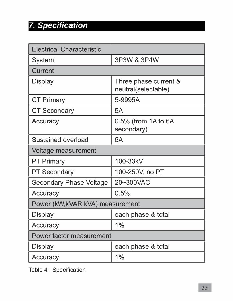
7. Specifi cation
Electrical CharacteristicSystem 3P3W & 3P4WCurrent Display Three phase current &
neutral(selectable) CT Primary 5-9995ACT Secondary 5AAccuracy 0.5% (from 1A to 6A
secondary)Sustained overload 6AVoltage measurementPT Primary 100-33kVPT Secondary 100-250V, no PTSecondary Phase Voltage 20~300VACAccuracy 0.5%Power (kW,kVAR,kVA) measurementDisplay each phase & totalAccuracy 1%Power factor measurementDisplay each phase & totalAccuracy 1%
Table 4 : Specifi cation

34
Frequency measurementRange 45~65HzAccuracy 0.5%Energy measurementActive IEC62053-21:Class 1Reactive IEC62053-23:Class 2Demand measurement Demand interval 60 to 1800 secondsDemand sub-interval 1 to 120 CommunicationHardware Interface Isolated RS485Protocol Modbus-RTUID 1 to 255Baudrate 2400, 4800, 9600, 19200,
38400 Parity None, even, oddOperating ConditionAuxiliary Supply 90~415VAC or 100~300VDCOperating Temperature -10 C ~ +55 CStorage Temperature -20 C ~ +70 COperating time (on hour) Up to 9999 days, 23 hours,
59 minutes.
Table 4: Specifi cation (cont)

35
Mechanical CharacteristicDimensionCase L96mm x W96mm x H105mmMounting type PanelLCD view area 76mmx56.5mmWeight 480gElectromagnetic Compatibility (EMC)Part 6-2: Generic Standards IEC61000-6-2
Immunity for industrial environments
Part 6-4: Generic Standards IEC61000-6-4
Emission standard for industrial environments
Table 4: Specifi cation (cont)

36
8. Modbus Data Register
By default, the data format in each register is unsigned 16-bit word. Shorter data may be encoded in the unsigned 8-bit byte format whereas longer data may be encoded either in the unsigned 32-bit double word format, signed 32-bit integer format or signed 64-bit long integer format. Two’s comple-ment is used to represent signed numbers. The nomencla-ture used in this manual is shown in Table 5.
8.1 Data Type
Data Length Unsigned Signed4-bit nibble -8-bit byte -16-bit word short32-bit dword int64-bit qword long
Table 5: Data length nomenclatureFor data with length shorter than 16 bits, the upper unused bits, nibbles or bytes can be ignored. In cases where multiple registers are required, the big endian convention shall apply unless otherwise specifi ed.
8.2 List Register
Tables 6 and 7 show the read only variables (function code 0x03 or 0x04) for device & communication info, operations, power factor and harmonics data respectively whereas Table 8 shows the read and write variables (function codes 0x03, 0x04 or 0x06) for the settings data.

37
Table 6: Device and communication register
Read Only (Function 0x03 or 0x04)
0-1 Reserved
2-3 Device Type
4-5 Version
Read Only (Function 0x03 or 0x04)
1000 Device ID 1-255
1001 Parity 1=none 2=even 3=odd
1002 Baudrate 1=2400 2=4800 3=9600 4=19200 5=38400
Table 7: Operation data registers
Read Only (Function 0x03 or 0x04)
Register Description Type Min. Unit Range
4000-4001
Negative Real Energy dword 1kWh 0~1000000M
4002-4003 Positive Real Energy dword 1kWh 0~1000000M
4004-4005 Reserved
4006-4007 Apparent Energy dword 1kVAh 0~1000000M
38
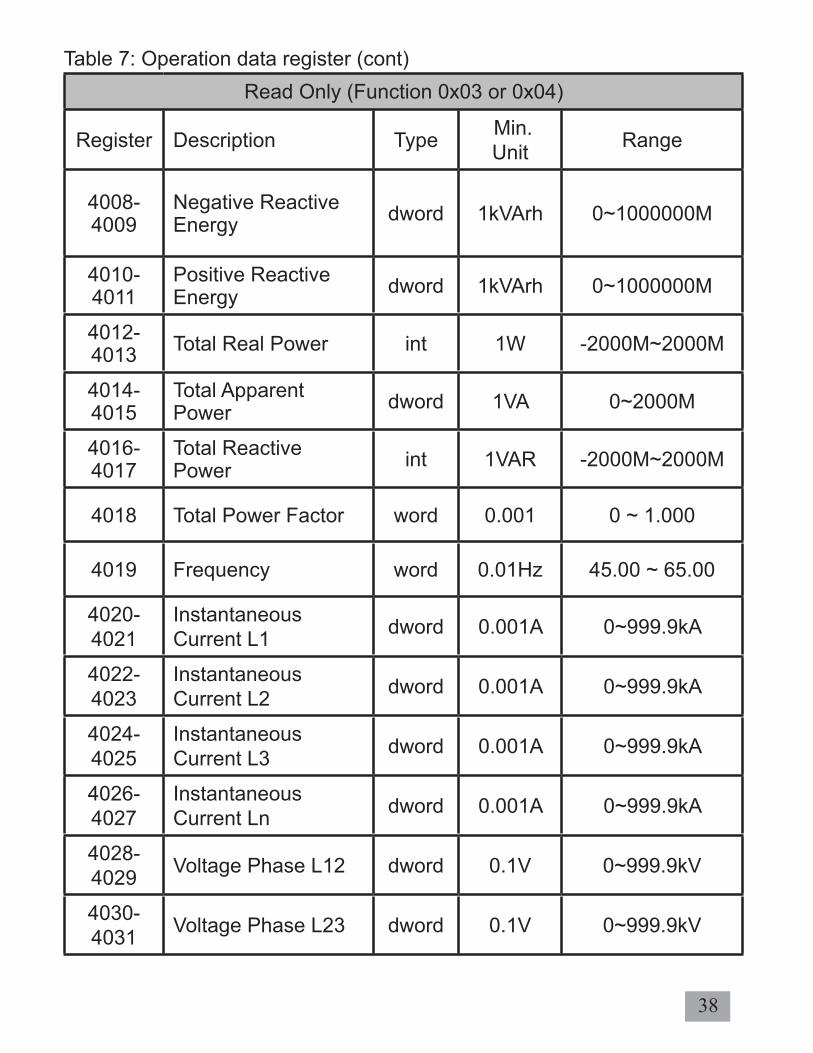
Read Only (Function 0x03 or 0x04)
Register Description Type Min. Unit Range
4008-4009
Negative Reactive Energy dword 1kVArh 0~1000000M
4010-4011
Positive Reactive Energy dword 1kVArh 0~1000000M
4012-4013 Total Real Power int 1W -2000M~2000M
4014-4015
Total Apparent Power dword 1VA 0~2000M
4016-4017
Total Reactive Power int 1VAR -2000M~2000M
4018 Total Power Factor word 0.001 0 ~ 1.000
4019 Frequency word 0.01Hz 45.00 ~ 65.00
4020-4021
Instantaneous Current L1 dword 0.001A 0~999.9kA
4022-4023
Instantaneous Current L2 dword 0.001A 0~999.9kA
4024-4025
Instantaneous Current L3 dword 0.001A 0~999.9kA
4026-4027
Instantaneous Current Ln dword 0.001A 0~999.9kA
4028-4029 Voltage Phase L12 dword 0.1V 0~999.9kV
4030-4031 Voltage Phase L23 dword 0.1V 0~999.9kV
Table 7: Operation data register (cont)

39
Read Only (Function 0x03 or 0x04)
Register Description Type Min. Unit Range
4032-4033
Voltage Phase L31 dword 0.1V 0~999.9kV
4034-4035 Voltage Phase L1 dword 0.1V 0~999.9kV
4036-4037 Voltage Phase L2 dword 0.1V 0~999.9kV
4038-4039 Voltage Phase L3 dword 0.1V 0~999.9kV
4040-4041 Real Power L1 int 1W -2000M~2000M
4042-4043 Real Power L2 int 1W -2000M~2000M
4044-4045 Real Power L3 int 1W -2000M~2000M
4046-4047
Apparent Power L1 dword 1VA 0 ~999.9M
4048-4049
Apparent Power L2 dword 1VA 0~999.9M
4050-4051
Apparent Power L3 dword 1VA 0~999.9M
4052-4053
Reactive Power L1 int 1VAR -2000M~2000M
4054-4055
Reactive Power L2 int 1VAR -2000M~2000M
4056-4057
Reactive Power L3 int 1VAR -2000M~2000M
Table 7: Operation data register (cont)

40
Read Only (Function 0x03 or 0x04)
Register Description Type Min. Unit Range
4058-4059
Total Demand Reactive Power int 1VAR -2000M~2000M
4060-4061
Max.Total Demand Reactive Power int 1VAR -2000M~2000M
4062-4063 Reserved
4064-4065
Total Demand Real Power int 1W -2000M~2000M
4066-4067
Max. Total Demand Real Power int 1W -2000M~2000M
4068-4069 Reserved
4070-4071
Total Demand Apparent Power dword 1VA 0~2000M
4072-4073
Max. Total Demand Apparent Power dword 1VA 0~2000M
4074-4075 Reserved
4076 Displacement Power Factor L1 word 0.001 0 ~ 1.000
4077 Displacement PF sign L1 word - 0=Resistive;
1=ind; 2=cap
4078 Displacement Power Factor L2 word 0.001 0 ~ 1.000
4079 Displacement PF sign L2 word - 0=Resistive;
1=ind; 2=cap
Table 7: Operation data register (cont)

41
Read Only (Function 0x03 or 0x04)
Register Description Type Min. Unit Range
4080 Displacement Power Factor L3 word 0.001 0 ~ 1.000
4081 Displacement PF sign L3 word - 0=Resistive;
1=ind; 2=cap
4082 THD Current L1 word 0.1% 0 ~ 1000
4083 THD Current L2 word 0.1% 0 ~ 1000
4084 THD Current L3 word 0.1% 0 ~ 1000
4085 THD Voltage L1 word 0.1% 0 ~ 1000
4086 THD Voltage L2 word 0.1% 0 ~ 1000
4087 THD Voltage L3 word 0.1% 0 ~ 1000
4088 Energy Full Flag word
*Energy fl agbit 7 to 5 = reservedbit 4 = (-)kVARhbit 3 = (-) kWhbit 2 = kVAhbit 1 = (+)kVARhbit 0 = (+)kWh
4089 Power Factor L1 word 0.001 0 ~ 1.000
4090 Sign Power Factor L1 word - 0=Resistive;
1=ind; 2=cap
4091 Power Factor L2 word 0.001 0 ~ 1.000
4092 Sign Power Factor L2 word - 0=Resistive;
1=ind; 2=cap
4093 Power Factor L3 word 0.001 0 ~ 1.000
4094 Sign Power Factor L3 word - 0=Resistive;
1=ind; 2=cap*if the energy is full, the bit is set to 1, else bit is 0.
Table 7: Operation data register (cont)

42
Read Only (Function 0x03 or 0x04)
Register Description Type Min. Unit Range
4095 Sign Total Power Factor word - 0=Resistive;
1=ind; 2=cap
4096- 4097 Current L1 Max. dword 0.001A 0~999.9kA
4098-4099 Reserved
4100- 4101 Current L2 Max. dword 0.001A 0~999.9kA
4102-4103 Reserved
4104- 4105 Current L3 Max. dword 0.001A 0~999.9kA
4106-4107 Reserved
4108- 4109 Current Ln Max. dword 0.001A 0~999.9kA
4110-4111 Reserved
4112- 4113 Voltage L1 Max. dword 0.1V 0~999.9kV
4114-4115 Reserved
4116- 4117 Voltage L2 Max. dword 0.1V 0~999.9kV
4118-4119 Reserved
Table 7: Operation data register (cont)

43
Read Only (Function 0x03 or 0x04)
Register Description Type Min. Unit Range
4120- 4121
Voltage L3 Max. dword 0.1V 0~999.9kV
4122-4123 Reserved
4124- 4125
Voltage L12 Max. dword 0.1V 0~999.9kV
4126-4127 Reserved
4128- 4129
Voltage L23 Max. dword 0.1V 0~999.9kV
4130-4131 Reserved
4132-4133
Voltage L31 Max. dword 0.1V 0~999.9kV
4134-4135 Reserved
4136- 4137
Total Real Power Max. int 1W -2000M~2000M
4138-4139 Reserved
4140- 4141
Total Apparent Power Max. dword 1VA 0~2000M
4142-4143 Reserved
4144- 4145
Total Reactive Power Max. int 1VAR -2000M~2000M
Table 7: Operation data register (cont)

44
Read Only (Function 0x03 or 0x04)
Register Description Type Min. Unit Range
4146-4147 Reserved
4148- 4149
Max. Real Power L1 int 1W -2000M~2000M
4150-4151 Reserved
4152- 4153
Max. Real Power L2 int 1W -2000M~2000M
4154-4155 Reserved
4156- 4157
Max. Real Power L3 int 1W -2000M~2000M
4158-4159 Reserved
4160- 4161
Max. Apparent Power L1 dword 1VA 0~2000M
4162-4163 Reserved
4164- 4165
Max. Apparent Power L2 dword 1VA 0~2000M
4166-4167 Reserved
4168- 4169
Max. Apparent Power L3 dword 1VA 0~2000M
Table 7: Operation data register (cont)

45
Read Only (Function 0x03 or 0x04)
Register Description Type Min. Unit Range
4170-4171 Reserved
4172- 4173
Max. Reactive Power L1 int 1VAR -2000M~2000M
4174-4175 Reserved
4176- 4177
Max. Reactive Power L2 int 1VAR -2000M~2000M
4178-4179 Reserved
4180- 4181
Max. Reactive Power L3 int 1VAR -2000M~2000M
4182-4183 Reserved
4184- 4185
Current L1 Min. dword 0.001A 0~999.9kA
4186-4187 Reserved
4188- 4189
Current L2 Min. dword 0.001A 0~999.9kA
4190-4191 Reserved
4192- 4193
Current L3 Min. dword 0.001A 0~999.9kA
4194-4195 Reserved
Table 7: Operation data register (cont)

46
Read Only (Function 0x03 or 0x04)
Register Description Type Min. Unit Range
4196- 4197 Current Ln Min. dword 0.001A 0~999.9kV
4198-4199 Reserved
4200- 4201 Voltage L1 Min. dword 0.1V 0~999.9kV
4202-4203 Reserved
4204- 4205 Voltage L2 Min. dword 0.1V 0~999.9kV
4206-4207 Reserved
4208- 4209 Voltage L3 Min. dword 0.1V 0~999.9kV
4210-4211 Reserved
4212- 4213 Voltage L12 Min. dword 0.1V 0~999.9kV
4214-4215 Reserved
4216- 4217 Voltage L23 Min. dword 0.1V 0~999.9kV
4218-4219 Reserved
4220- 4221
Voltage L31 Min. dword 0.1V 0~999.9kV
Table 7: Operation data register (cont)

47
Read Only (Function 0x03 or 0x04)
Register Description Type Min. Unit Range
4222-4223 Reserved
4224-4225
Total Real Power Min. int 1W -2000M~2000M
4226-4227 Reserved
4228- 4229
Total Apparent Power Min. dword 1VA 0~2000M
4230-4231 Reserved
4232- 4233
Total Reactive Power Min. int 1VAR -2000M~2000M
4234-4235 Reserved
4236- 4237
Real Power Min. L1 int 1W -2000M~2000M
4238-4239 Reserved
4240- 4241
Real Power Min. L2 int 1W -2000M~2000M
4242-4243 Reserved
4244- 4245
Real Power Min. L3 int 1W -2000M~2000M
4246-4247 Reserved
Table 7: Operation data register (cont)
48
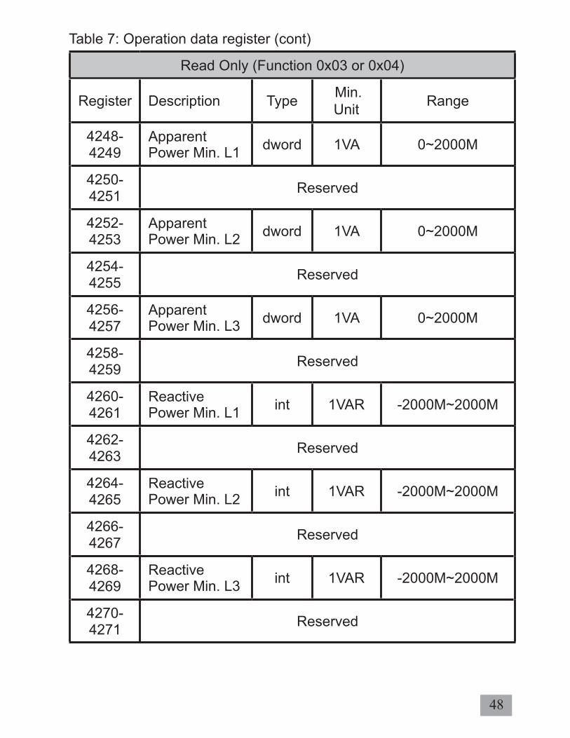
Read Only (Function 0x03 or 0x04)
Register Description Type Min. Unit Range
4248- 4249
Apparent Power Min. L1 dword 1VA 0~2000M
4250-4251 Reserved
4252- 4253
Apparent Power Min. L2 dword 1VA 0~2000M
4254-4255 Reserved
4256- 4257
Apparent Power Min. L3 dword 1VA 0~2000M
4258-4259 Reserved
4260-4261
Reactive Power Min. L1 int 1VAR -2000M~2000M
4262-4263 Reserved
4264- 4265
Reactive Power Min. L2 int 1VAR -2000M~2000M
4266-4267 Reserved
4268- 4269
Reactive Power Min. L3 int 1VAR -2000M~2000M
4270-4271 Reserved
Table 7: Operation data register (cont)

49
Read or write (Function 0x03,0x04 or 0x06)
Register Description Range100 PT ratio primary 100~33kV
101 PT ratio secondary 100~250V
102 CT ratio primary 5~9995A
103 CT ratio secondary 5A
104 Interval Demand 60~1800s
105 Sub-Interval Demand 1~120
106 System Confi guration 3P4W/ 3P3W
107 Backlight setting ON/OFF
108 System scroll setting ON/OFF
109 Scroll interval 1-10 secs
110 Neutral setting ON/OFF
111 Minutes 0-59mins
112 Hours 0-23hrs
113 Days 0-9999day
NOTE: Register list is based on fi rmware version 1.0
Table 8: Setting data register

50
The power meter does not contain any user-serviceable parts. If the power meter requires service, please contact your local sales representative. Do not open the power me-ter. Opening the power meter voids the warranty.
NOTE: We reserve the right to alter or modify the information contained herein at any time in line with our product de-velopment without prior notifi cation. We also reserve the right to discontinue production & delivery of product.
9. Maintenance and Troubleshooting
51
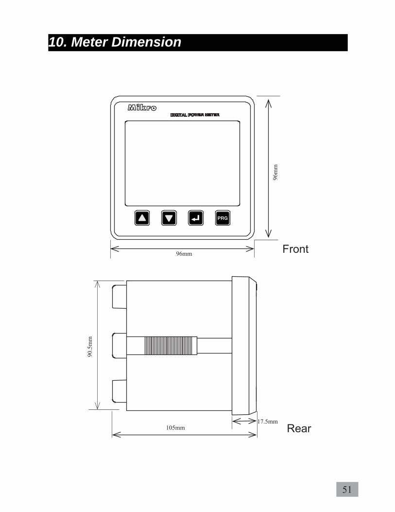
Rear
10. Meter Dimension
96mm
96m
m
90.5
mm
105mm17.5mm
Front

52
Back
90.5mm
90.5mm
1 2 3 4 5 6 7 8
9 10 11 12 13 14
15 16 17 18 19 20

53
11. Appendix
11.1. DEMAND CALCULATION 11.1. DEMAND CALCULATION
Demand parameters are used to show average values over a demand interval.This power meter using sliding block method. The demand value is based on interval divide by sub-interval time. Example is shown below:
SETTING: Interval time = 180 seconds ; sub-interval = 3
Measurement= interval time/sub-interval= 180/3= 60 seconds
is1 is2 is3 is4 is5
---------
---------
id1=(is1+is2+is3)/3
60s60s
60s60s
60s
id2=(is2+is3+is4)/3
id3=(is3+is4+is5)/3
---------
---------

54
11.2. DATA READ FORMAT FROM MODBUS 11.2. DATA READ FORMAT FROM MODBUS
a) 4000-4001 : Negative Real Energy
Address 4000 Address 4001MSB LSB MSB LSB0x00 0x01 0x23 0x34
Negative Real Energy = 0x00012334 =74548 x 1kWh (min value) =74548kWh
b) 4012-4013 : Total Real Power; (Signed register)
Address 4012 Address 4013MSB LSB MSB LSB0xFF 0xFB 0x6C 0x20
Total Real Power = 0xFFFB6C20If MSB is “1”, it is negative value;Total Real Power = 0xFFFB6C20 x (-1); = 0x493E0; 300 000 = 300000 x 1W(min value) = -300kW