digital power factor correction using xmc4400...power factor correction is achieved by forcing the...
TRANSCRIPT
Appl icat ion Guide V1.0 2013-06
XMC4000 Microcontroller Series for Industrial Applications
Digi ta l Power Factor Correct ion using XMC4400
Microcontrol lers
Edition 2013-06
Published by Infineon Technologies AG,
81726 Munich, Germany.
© 2013 Infineon Technologies AG
All Rights Reserved.
LEGAL DISCLAIMER
THE INFORMATION GIVEN IN THIS APPLICATION NOTE IS GIVEN AS A HINT FOR THE
IMPLEMENTATION OF THE INFINEON TECHNOLOGIES COMPONENT ONLY AND SHALL NOT BE
REGARDED AS ANY DESCRIPTION OR WARRANTY OF A CERTAIN FUNCTIONALITY, CONDITION OR
QUALITY OF THE INFINEON TECHNOLOGIES COMPONENT. THE RECIPIENT OF THIS APPLICATION
NOTE MUST VERIFY ANY FUNCTION DESCRIBED HEREIN IN THE REAL APPLICATION. INFINEON
TECHNOLOGIES HEREBY DISCLAIMS ANY AND ALL WARRANTIES AND LIABILITIES OF ANY KIND
(INCLUDING WITHOUT LIMITATION WARRANTIES OF NON-INFRINGEMENT OF INTELLECTUAL
PROPERTY RIGHTS OF ANY THIRD PARTY) WITH RESPECT TO ANY AND ALL INFORMATION GIVEN IN
THIS APPLICATION NOTE.
Information
For further information on technology, delivery terms and conditions and prices, please contact the nearest
Infineon Technologies Office (www.infineon.com).
Warnings
Due to technical requirements, components may contain dangerous substances. For information on the types in
question, please contact the nearest Infineon Technologies Office.
Infineon Technologies components may be used in life-support devices or systems only with the express written
approval of Infineon Technologies, if a failure of such components can reasonably be expected to cause the
failure of that life-support device or system or to affect the safety or effectiveness of that device or system. Life
support devices or systems are intended to be implanted in the human body or to support and/or maintain and
sustain and/or protect human life. If they fail, it is reasonable to assume that the health of the user or other
persons may be endangered.
Digital Power Factor Correction using XMC4400
Application Guide 3 V1.0, 2013-06
Trademarks of Infineon Technologies AG
AURIX™, C166™, CanPAK™, CIPOS™, CIPURSE™, EconoPACK™, CoolMOS™, CoolSET™,
CORECONTROL™, CROSSAVE™, DAVE™, DI-POL™, EasyPIM™, EconoBRIDGE™, EconoDUAL™,
EconoPIM™, EconoPACK™, EiceDRIVER™, eupec™, FCOS™, HITFET™, HybridPACK™, I²RF™,
ISOFACE™, IsoPACK™, MIPAQ™, ModSTACK™, my-d™, NovalithIC™, OptiMOS™, ORIGA™,
POWERCODE™; PRIMARION™, PrimePACK™, PrimeSTACK™, PRO-SIL™, PROFET™, RASIC™,
ReverSave™, SatRIC™, SIEGET™, SINDRION™, SIPMOS™, SmartLEWIS™, SOLID FLASH™,
TEMPFET™, thinQ!™, TRENCHSTOP™, TriCore™.
Other Trademarks
Advance Design System™ (ADS) of Agilent Technologies, AMBA™, ARM™, MULTI-ICE™, KEIL™,
PRIMECELL™, REALVIEW™, THUMB™, µVision™ of ARM Limited, UK. AUTOSAR™ is licensed by
AUTOSAR development partnership. Bluetooth™ of Bluetooth SIG Inc. CAT-iq™ of DECT Forum.
COLOSSUS™, FirstGPS™ of Trimble Navigation Ltd. EMV™ of EMVCo, LLC (Visa Holdings Inc.). EPCOS™
of Epcos AG. FLEXGO™ of Microsoft Corporation. FlexRay™ is licensed by FlexRay Consort ium.
HYPERTERMINAL™ of Hilgraeve Incorporated. IEC™ of Commission Electrotechnique Internationale. IrDA™
of Infrared Data Association Corporation. ISO™ of INTERNATIONAL ORGANIZATION FOR
STANDARDIZATION. MATLAB™ of MathWorks, Inc. MAXIM™ of Maxim Integrated Products, Inc.
MICROTEC™, NUCLEUS™ of Mentor Graphics Corporation. MIPI™ of MIPI Alliance, Inc. MIPS™ of MIPS
Technologies, Inc., USA. muRata™ of MURATA MANUFACTURING CO., MICROWAVE OFFICE™ (MWO) of
Applied Wave Research Inc., OmniVision™ of OmniVision Technologies, Inc. Openwave™ Openwave Systems
Inc. RED HAT™ Red Hat, Inc. RFMD™ RF Micro Devices, Inc. SIRIUS™ of Sirius Satellite Radio Inc.
SOLARIS™ of Sun Microsystems, Inc. SPANSION™ of Spansion LLC Ltd. Symbian™ of Symbian Software
Limited. TAIYO YUDEN™ of Taiyo Yuden Co. TEAKLITE™ of CEVA, Inc. TEKTRONIX™ of Tektronix Inc.
TOKO™ of TOKO KABUSHIKI KAISHA TA. UNIX™ of X/Open Company Limited. VERILOG™, PALLADIUM™
of Cadence Design Systems, Inc. VLYNQ™ of Texas Instruments Incorporated. VXWORKS™, WIND RIVER™
of WIND RIVER SYSTEMS, INC. ZETEX™ of Diodes Zetex Limited.
Last Trademarks Update 2011-11-11

Digital Power Factor Correction using XMC4400
Application Guide 4 V1.0, 2013-06
Revision History
Major changes since previous revision
Date Version Changed By Change Description
12 Jun 2013 1.0 Initial version
We Listen to Your Comments
Is there any information in this document that you feel is wrong, unclear or missing?
Your feedback will help us to continuously improve the quality of our documentation.
Please send your proposal (including a reference to this document title/number) to:
Digital Power Factor Correction using XMC4400
Application Guide 5 V1.0, 2013-06
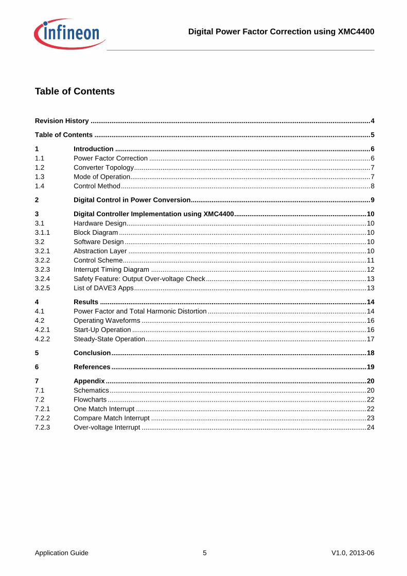
Table of Contents
Revision History .................................................................................................................................................... 4
Table of Contents .................................................................................................................................................. 5
1 Introduction ....................................................................................................................................... 6 1.1 Power Factor Correction ..................................................................................................................... 6 1.2 Converter Topology ............................................................................................................................. 7 1.3 Mode of Operation............................................................................................................................... 7 1.4 Control Method .................................................................................................................................... 8
2 Digital Control in Power Conversion............................................................................................... 9
3 Digital Controller Implementation using XMC4400 ...................................................................... 10 3.1 Hardware Design............................................................................................................................... 10 3.1.1 Block Diagram ................................................................................................................................... 10 3.2 Software Design ................................................................................................................................ 10 3.2.1 Abstraction Layer .............................................................................................................................. 10 3.2.2 Control Scheme................................................................................................................................. 11 3.2.3 Interrupt Timing Diagram .................................................................................................................. 12 3.2.4 Safety Feature: Output Over-voltage Check ..................................................................................... 13 3.2.5 List of DAVE3 Apps ........................................................................................................................... 13
4 Results ............................................................................................................................................. 14 4.1 Power Factor and Total Harmonic Distortion .................................................................................... 14 4.2 Operating Waveforms ....................................................................................................................... 16 4.2.1 Start-Up Operation ............................................................................................................................ 16 4.2.2 Steady-State Operation ..................................................................................................................... 17
5 Conclusion ....................................................................................................................................... 18
6 References ....................................................................................................................................... 19
7 Appendix .......................................................................................................................................... 20 7.1 Schematics ........................................................................................................................................ 20 7.2 Flowcharts ......................................................................................................................................... 22 7.2.1 One Match Interrupt .......................................................................................................................... 22 7.2.2 Compare Match Interrupt .................................................................................................................. 23 7.2.3 Over-voltage Interrupt ....................................................................................................................... 24
Digital Power Factor Correction using XMC4400
Introduction
Application Guide 6 V1.0, 2013-06
1 Introduction
This application guide describes the implementation of digital Power Factor Correction (PFC) operating in
Continuous Conduction Mode (CCM) using XMC4400, a 32-bit ARM Cortex M4-based microcontroller from
Infineon.
1.1 Power Factor Correction
The power factor quality in an AC system can be analysed by looking at two factors:
The displacement angle
The Total Harmonic Distortion (THD) of the input current waveform against input voltage
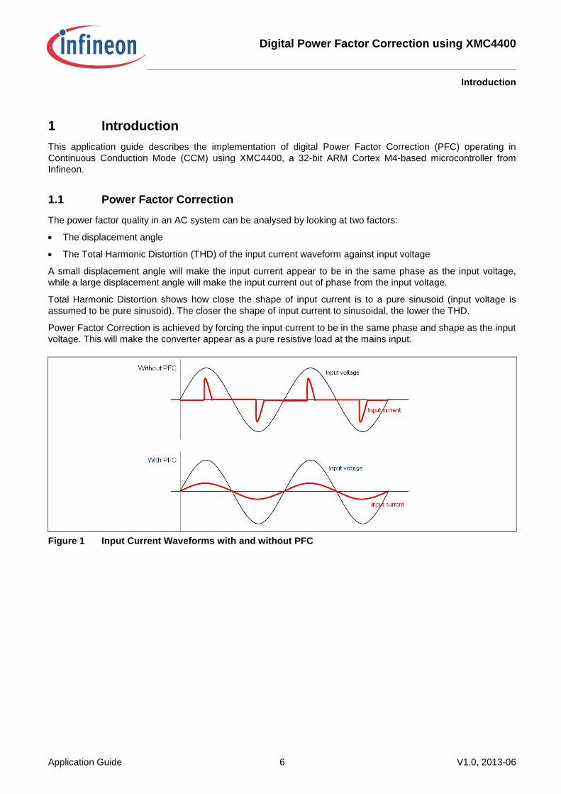
A small displacement angle will make the input current appear to be in the same phase as the input voltage,
while a large displacement angle will make the input current out of phase from the input voltage.
Total Harmonic Distortion shows how close the shape of input current is to a pure sinusoid (input voltage is
assumed to be pure sinusoid). The closer the shape of input current to sinusoidal, the lower the THD.
Power Factor Correction is achieved by forcing the input current to be in the same phase and shape as the input
voltage. This will make the converter appear as a pure resistive load at the mains input.
Figure 1 Input Current Waveforms with and without PFC
Digital Power Factor Correction using XMC4400
Introduction
Application Guide 7 V1.0, 2013-06
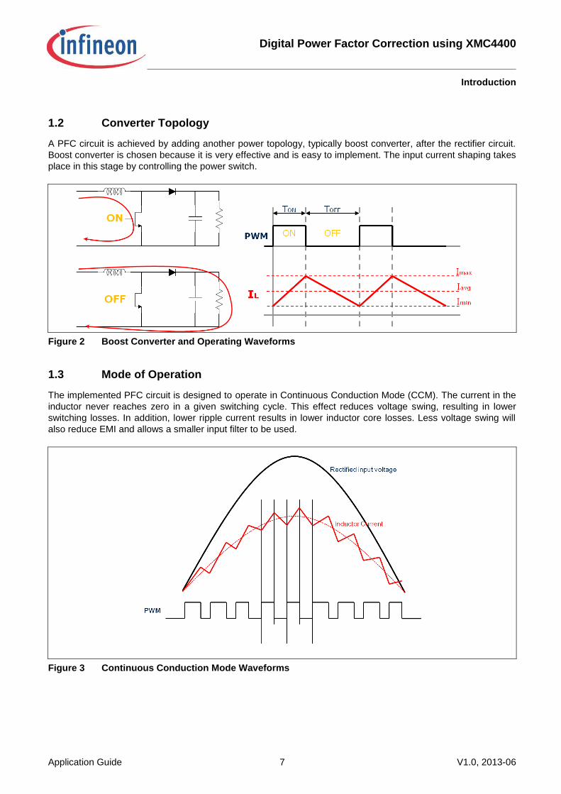
1.2 Converter Topology
A PFC circuit is achieved by adding another power topology, typically boost converter, after the rectifier circuit.
Boost converter is chosen because it is very effective and is easy to implement. The input current shaping takes
place in this stage by controlling the power switch.
Figure 2 Boost Converter and Operating Waveforms
1.3 Mode of Operation
The implemented PFC circuit is designed to operate in Continuous Conduction Mode (CCM). The current in the
inductor never reaches zero in a given switching cycle. This effect reduces voltage swing, resulting in lower
switching losses. In addition, lower ripple current results in lower inductor core losses. Less voltage swing will
also reduce EMI and allows a smaller input filter to be used.
Figure 3 Continuous Conduction Mode Waveforms
Digital Power Factor Correction using XMC4400
Introduction
Application Guide 8 V1.0, 2013-06
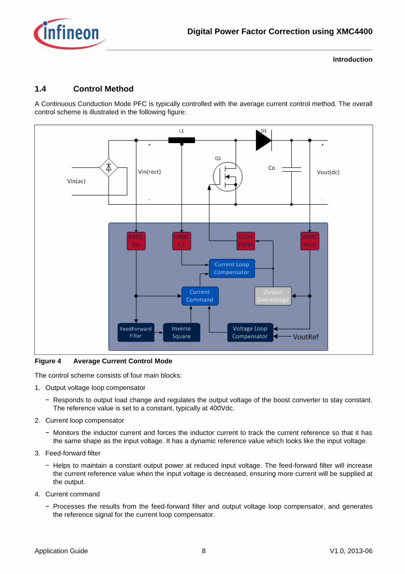
1.4 Control Method
A Continuous Conduction Mode PFC is typically controlled with the average current control method. The overall
control scheme is illustrated in the following figure:
Figure 4 Average Current Control Mode
The control scheme consists of four main blocks:
1. Output voltage loop compensator
− Responds to output load change and regulates the output voltage of the boost converter to stay constant.
The reference value is set to a constant, typically at 400Vdc.
2. Current loop compensator
− Monitors the inductor current and forces the inductor current to track the current reference so that it has
the same shape as the input voltage. It has a dynamic reference value which looks like the input voltage.
3. Feed-forward filter
− Helps to maintain a constant output power at reduced input voltage. The feed-forward filter will increase
the current reference value when the input voltage is decreased, ensuring more current will be supplied at
the output.
4. Current command
− Processes the results from the feed-forward filter and output voltage loop compensator, and generates
the reference signal for the current loop compensator.
Digital Power Factor Correction using XMC4400
Digital Control in Power Conversion
Application Guide 9 V1.0, 2013-06
2 Digital Control in Power Conversion
In the past, a Switched-Mode Power Supply (SMPS) was controlled using an analog solution. With the
availability of low-cost, high-performance microcontrollers however, it is now possible to control SMPS digitally.
Digital control in power conversion offers several benefits over the analog counterpart. First, it offers a
communication capability, which enables the power supply to detect and report fault conditions and notify the
user. Several power supplies can be combined together for load sharing. The power supplies will communicate
to balance the power supplied to the load.
Secondly, SMPS is a non-linear system. Using digital control, it is possible to implement complex, non-linear
control algorithms to compensate for the non-linearity of the SMPS. In addition, since all the controllers can be
implemented digitally, it reduces the component count for such complex control circuits, and hence reduces the
overall power supply costs.
The PFC controller described in this application note is implemented using XMC4400, a 32-bit ARM Cortex M4
based microcontroller from Infineon. It has a single-cycle Multiply-Accumulate (MAC) instruction and Floating-
Point Unit dedicated for calculation intensive algorithms. In addition, it also has dedicated control peripherals
such as the Capture Compare Unit 4 (CCU4) module for PWM generation and a Versatile Analog-to-Digital
(VADC) module for analog signal measurement, making it suitable for applications that require fast, cycle-by-
cycle calculation such as the Average Current Control mode.
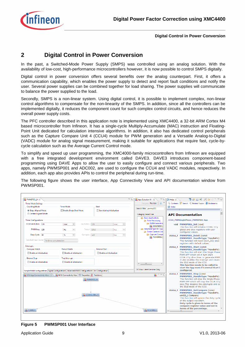
To simplify and speed up user programming, the XMC4000-family microcontrollers from Infineon are equipped
with a free integrated development environment called DAVE3. DAVE3 introduces component-based
programming using DAVE Apps to allow the user to easily configure and connect various peripherals. Two
apps, namely PWMSP001 and ADC002, are used to configure the CCU4 and VADC modules, respectively. In
addition, each app also provides APIs to control the peripheral during run-time.
The following figure shows the user interface, App Connectivity View and API documentation window from
PWMSP001.
Figure 5 PWMSP001 User Interface
Digital Power Factor Correction using XMC4400
Digital Controller Implementation using XMC4400
Application Guide 10 V1.0, 2013-06
3 Digital Controller Implementation using XMC4400
3.1 Hardware Design
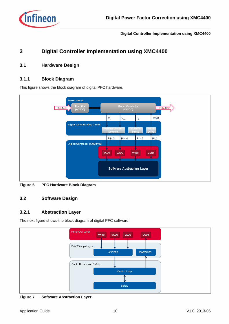
3.1.1 Block Diagram
This figure shows the block diagram of digital PFC hardware.
Figure 6 PFC Hardware Block Diagram
3.2 Software Design
3.2.1 Abstraction Layer
The next figure shows the block diagram of digital PFC software.
Figure 7 Software Abstraction Layer
Digital Power Factor Correction using XMC4400
Digital Controller Implementation using XMC4400
Application Guide 11 V1.0, 2013-06
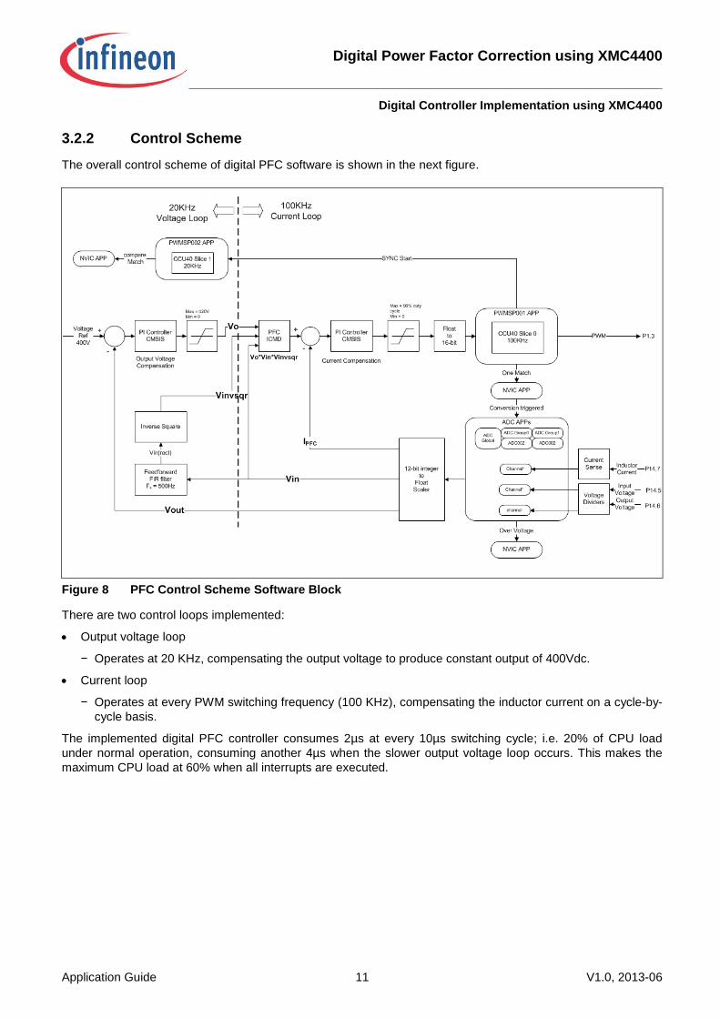
3.2.2 Control Scheme
The overall control scheme of digital PFC software is shown in the next figure.
Figure 8 PFC Control Scheme Software Block
There are two control loops implemented:
Output voltage loop
− Operates at 20 KHz, compensating the output voltage to produce constant output of 400Vdc.
Current loop
− Operates at every PWM switching frequency (100 KHz), compensating the inductor current on a cycle-by-
cycle basis.
The implemented digital PFC controller consumes 2µs at every 10µs switching cycle; i.e. 20% of CPU load
under normal operation, consuming another 4µs when the slower output voltage loop occurs. This makes the
maximum CPU load at 60% when all interrupts are executed.
Digital Power Factor Correction using XMC4400
Digital Controller Implementation using XMC4400
Application Guide 12 V1.0, 2013-06
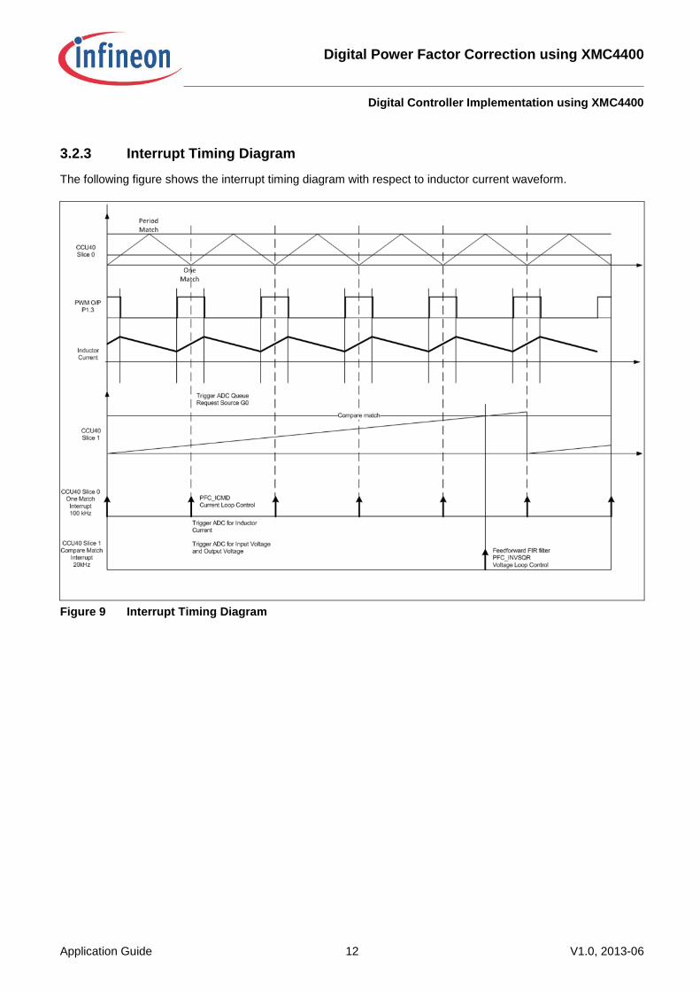
3.2.3 Interrupt Timing Diagram
The following figure shows the interrupt timing diagram with respect to inductor current waveform.
Figure 9 Interrupt Timing Diagram
Digital Power Factor Correction using XMC4400
Digital Controller Implementation using XMC4400
Application Guide 13 V1.0, 2013-06
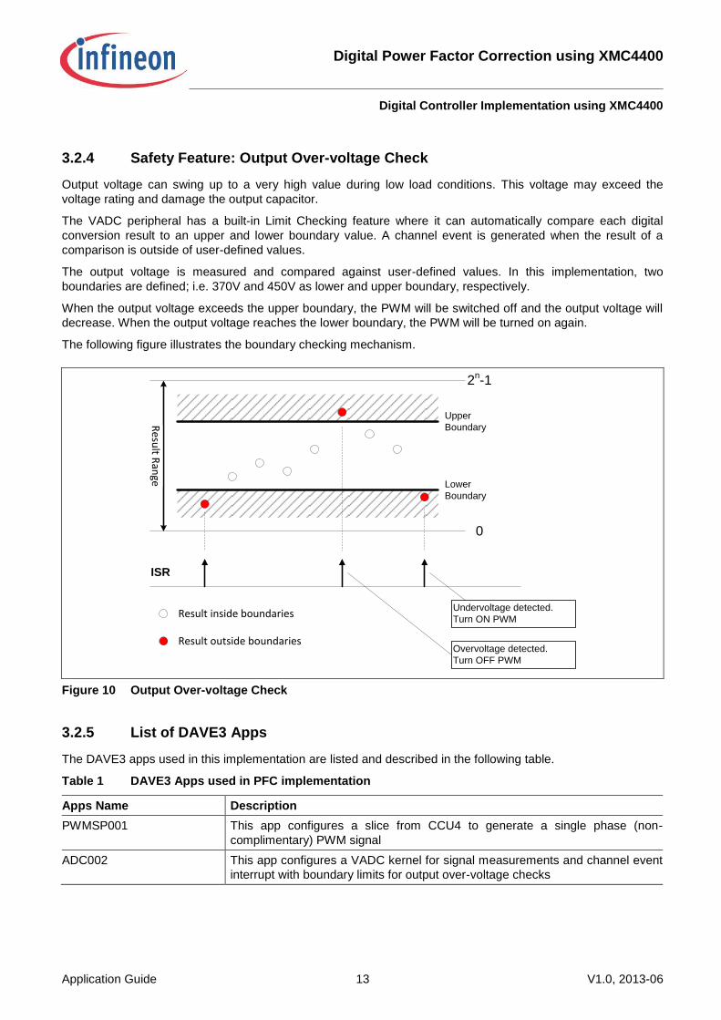
3.2.4 Safety Feature: Output Over-voltage Check
Output voltage can swing up to a very high value during low load conditions. This voltage may exceed the
voltage rating and damage the output capacitor.
The VADC peripheral has a built-in Limit Checking feature where it can automatically compare each digital
conversion result to an upper and lower boundary value. A channel event is generated when the result of a
comparison is outside of user-defined values.
The output voltage is measured and compared against user-defined values. In this implementation, two
boundaries are defined; i.e. 370V and 450V as lower and upper boundary, respectively.
When the output voltage exceeds the upper boundary, the PWM will be switched off and the output voltage will
decrease. When the output voltage reaches the lower boundary, the PWM will be turned on again.
The following figure illustrates the boundary checking mechanism.
Figure 10 Output Over-voltage Check
3.2.5 List of DAVE3 Apps
The DAVE3 apps used in this implementation are listed and described in the following table.
Table 1 DAVE3 Apps used in PFC implementation
Apps Name Description
PWMSP001 This app configures a slice from CCU4 to generate a single phase (non-
complimentary) PWM signal
ADC002 This app configures a VADC kernel for signal measurements and channel event
interrupt with boundary limits for output over-voltage checks
2n-1
0
Upper
Boundary
Lower
Boundary
Resu
lt Ran
geISR
Result inside boundaries
Result outside boundaries
Undervoltage detected.
Turn ON PWM
Overvoltage detected.
Turn OFF PWM
Digital Power Factor Correction using XMC4400
Results
Application Guide 14 V1.0, 2013-06
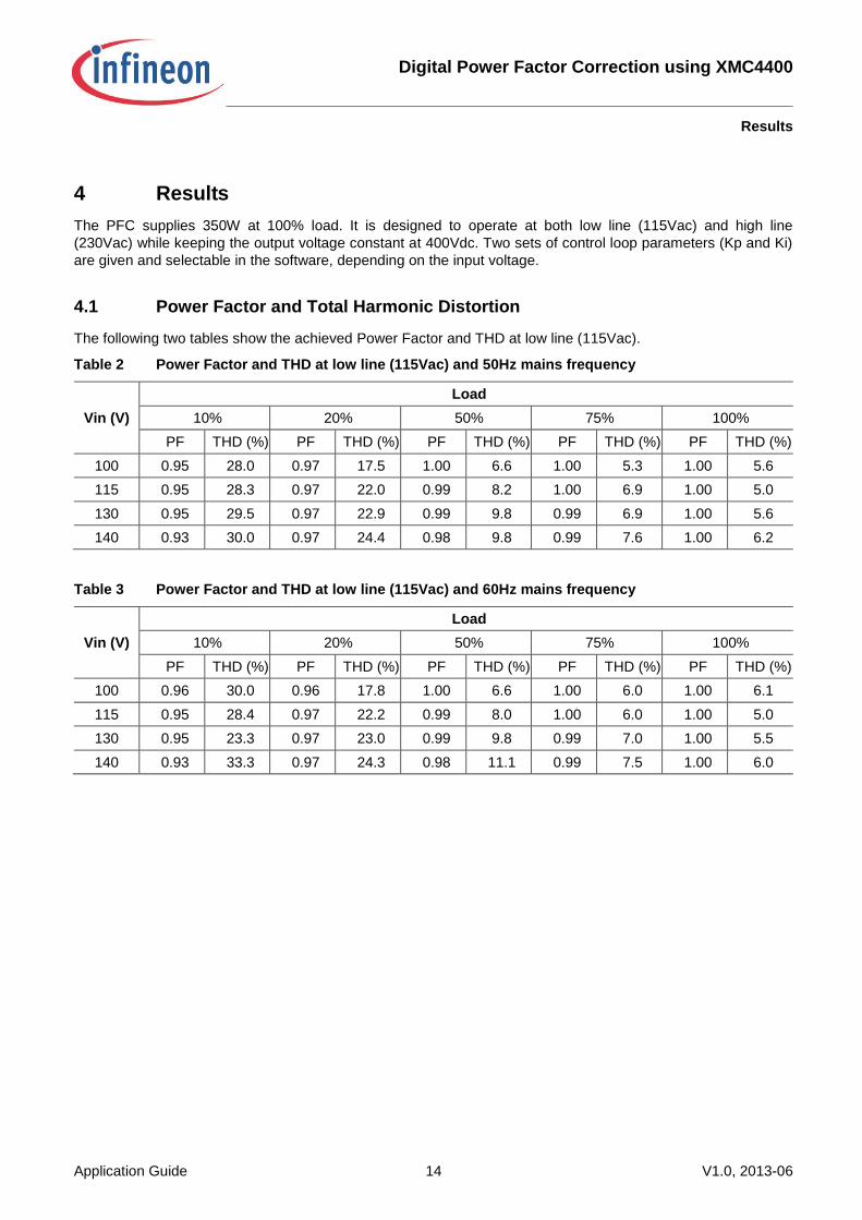
4 Results
The PFC supplies 350W at 100% load. It is designed to operate at both low line (115Vac) and high line
(230Vac) while keeping the output voltage constant at 400Vdc. Two sets of control loop parameters (Kp and Ki)
are given and selectable in the software, depending on the input voltage.
4.1 Power Factor and Total Harmonic Distortion
The following two tables show the achieved Power Factor and THD at low line (115Vac).
Table 2 Power Factor and THD at low line (115Vac) and 50Hz mains frequency
Vin (V)
Load
10% 20% 50% 75% 100%
PF THD (%) PF THD (%) PF THD (%) PF THD (%) PF THD (%)
100 0.95 28.0 0.97 17.5 1.00 6.6 1.00 5.3 1.00 5.6
115 0.95 28.3 0.97 22.0 0.99 8.2 1.00 6.9 1.00 5.0
130 0.95 29.5 0.97 22.9 0.99 9.8 0.99 6.9 1.00 5.6
140 0.93 30.0 0.97 24.4 0.98 9.8 0.99 7.6 1.00 6.2
Table 3 Power Factor and THD at low line (115Vac) and 60Hz mains frequency
Vin (V)
Load
10% 20% 50% 75% 100%
PF THD (%) PF THD (%) PF THD (%) PF THD (%) PF THD (%)
100 0.96 30.0 0.96 17.8 1.00 6.6 1.00 6.0 1.00 6.1
115 0.95 28.4 0.97 22.2 0.99 8.0 1.00 6.0 1.00 5.0
130 0.95 23.3 0.97 23.0 0.99 9.8 0.99 7.0 1.00 5.5
140 0.93 33.3 0.97 24.3 0.98 11.1 0.99 7.5 1.00 6.0
Digital Power Factor Correction using XMC4400
Results
Application Guide 15 V1.0, 2013-06
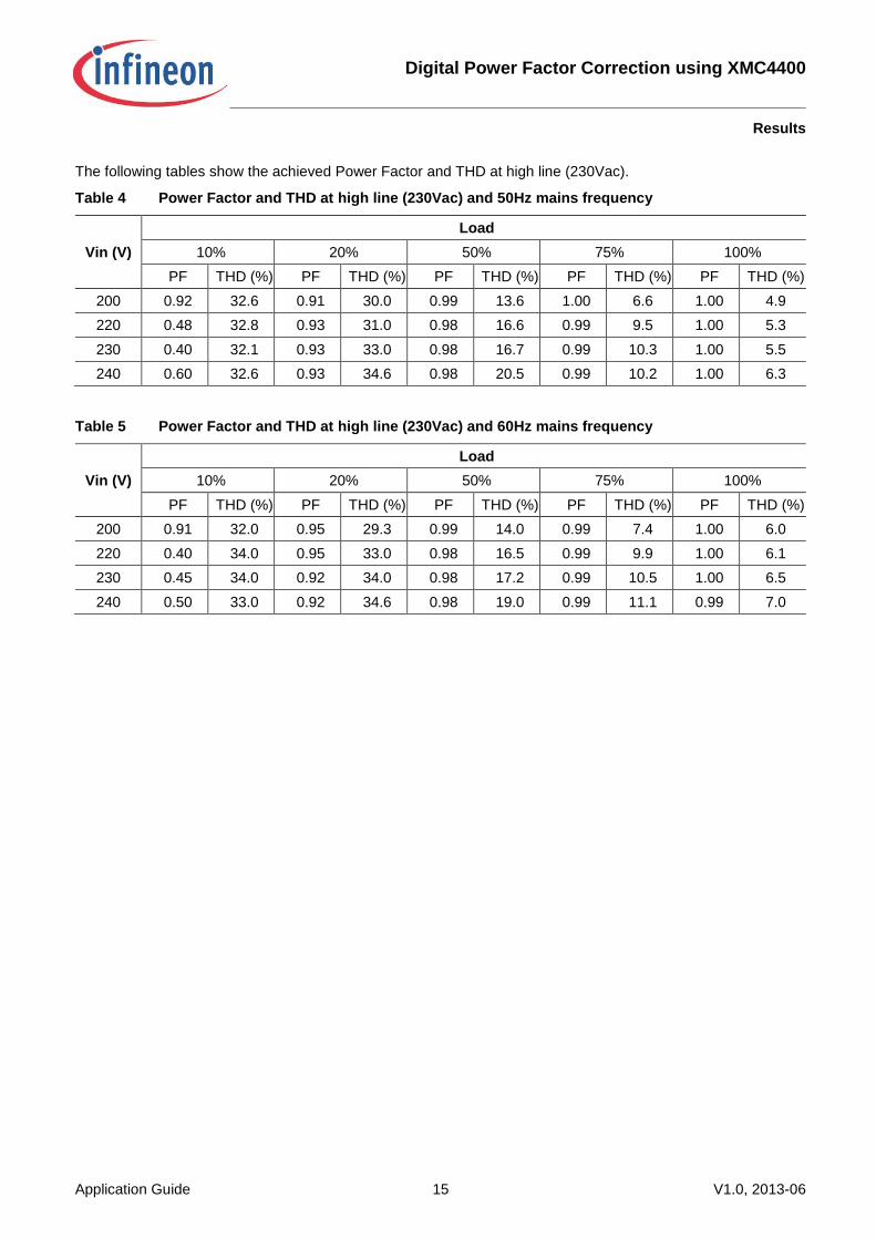
The following tables show the achieved Power Factor and THD at high line (230Vac).
Table 4 Power Factor and THD at high line (230Vac) and 50Hz mains frequency
Vin (V)
Load
10% 20% 50% 75% 100%
PF THD (%) PF THD (%) PF THD (%) PF THD (%) PF THD (%)
200 0.92 32.6 0.91 30.0 0.99 13.6 1.00 6.6 1.00 4.9
220 0.48 32.8 0.93 31.0 0.98 16.6 0.99 9.5 1.00 5.3
230 0.40 32.1 0.93 33.0 0.98 16.7 0.99 10.3 1.00 5.5
240 0.60 32.6 0.93 34.6 0.98 20.5 0.99 10.2 1.00 6.3
Table 5 Power Factor and THD at high line (230Vac) and 60Hz mains frequency
Vin (V)
Load
10% 20% 50% 75% 100%
PF THD (%) PF THD (%) PF THD (%) PF THD (%) PF THD (%)
200 0.91 32.0 0.95 29.3 0.99 14.0 0.99 7.4 1.00 6.0
220 0.40 34.0 0.95 33.0 0.98 16.5 0.99 9.9 1.00 6.1
230 0.45 34.0 0.92 34.0 0.98 17.2 0.99 10.5 1.00 6.5
240 0.50 33.0 0.92 34.6 0.98 19.0 0.99 11.1 0.99 7.0

Digital Power Factor Correction using XMC4400
Results
Application Guide 16 V1.0, 2013-06
4.2 Operating Waveforms
4.2.1 Start-Up Operation
The following figures show the start-up waveform of output voltage and input current at 100% load.
Figure 11 Start-Up Operating Waveforms at Low Line
Figure 12 Start-Up Operating Waveforms at High Line
Digital Power Factor Correction using XMC4400
Results
Application Guide 17 V1.0, 2013-06
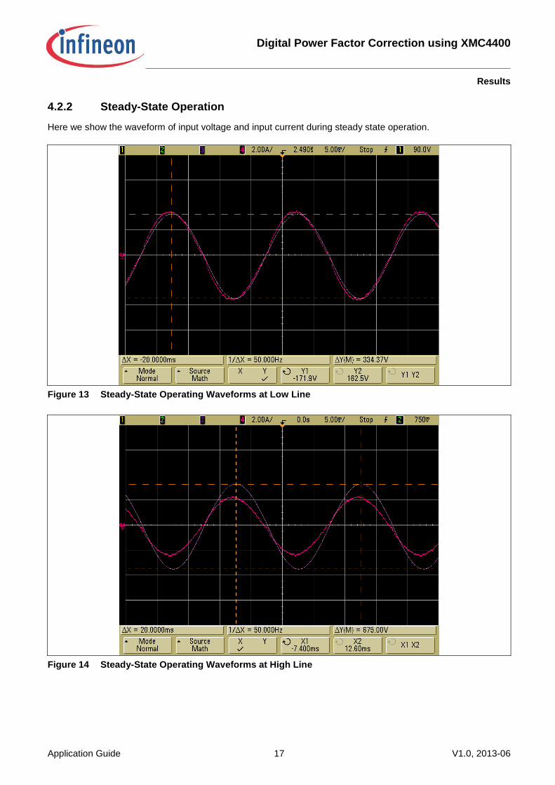
4.2.2 Steady-State Operation
Here we show the waveform of input voltage and input current during steady state operation.
Figure 13 Steady-State Operating Waveforms at Low Line
Figure 14 Steady-State Operating Waveforms at High Line
Digital Power Factor Correction using XMC4400
Conclusion
Application Guide 18 V1.0, 2013-06
5 Conclusion
This application guide has described digital Power Factor Correction operating in Continuous Conduction Mode
implemented on the XMC4400, an ARM Cortex M4-based microcontroller from Infineon. Two peripherals,
namely VADC and CCU4, are used to implement the PFC controller. The PFC is controlled with the Average
Current Control method operating at 100 KHz with an average of 20% CPU load.
The PFC is designed to operate at both low line (115Vac) and high line (230Vac), while keeping constant output
voltage at 400Vdc. Two sets of control loop parameters are tuned and optimized for each operating line and are
selectable by software. This feature highlights the benefit of digital control over the analog counterpart in which
only one set of control loop parameters can be implemented and optimized across operating input voltage.
The PFC supplied 350W at 100% full load. The measurements are taken at low line and high line, 50Hz and
60Hz mains frequencies. The results show that the PFC can achieve a Power Factor close to 1.0 and THD at
around 5.5% at full load.
This application guide has demonstrated the implementation of a digital controller for PFC with average CCM,
which demands high processing power from the controller. The implementation shows that the XMC4400 is able
to provide such processing power and the measurement results indicate that the digital controller can match, if
not outperform, the performance of the analog controller.

Digital Power Factor Correction using XMC4400
References
Application Guide 19 V1.0, 2013-06
6 References
[1] M. Xie, “Digital Control for Power Factor Correction”, Virginia Polytechnic Institute and State University,
2003
[2] L.H. Dixon, “Average Current Mode Control of Switching Power Supplies”, Unitrode Power Supply Design
Seminar Manual SEM700, 1990
[3] L.H. Dixon, “High Power Factor Switching Preregulator Design Optimization”, Unitrode Power Supply
Design Seminar Manual SEM700, 1990
[4] XMC4400 Reference Manual version 1.1, November 2012
Digital Power Factor Correction using XMC4400
Appendix
Application Guide 20 V1.0, 2013-06
7 Appendix
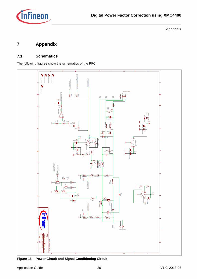
7.1 Schematics
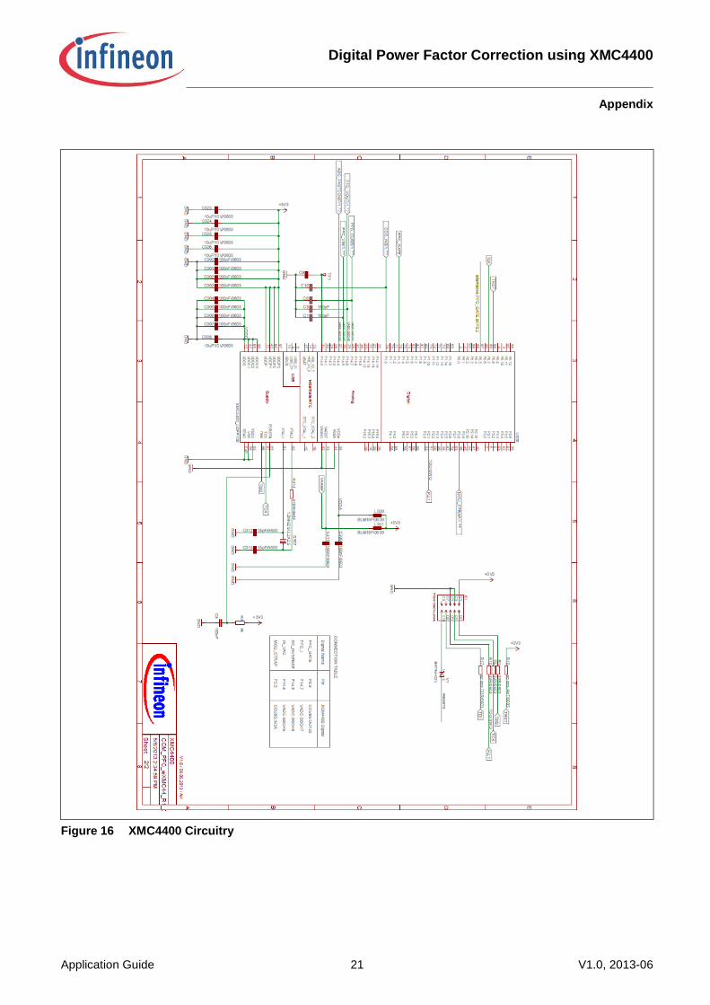
The following figures show the schematics of the PFC.
Figure 15 Power Circuit and Signal Conditioning Circuit
Digital Power Factor Correction using XMC4400
Appendix
Application Guide 21 V1.0, 2013-06
Figure 16 XMC4400 Circuitry

Digital Power Factor Correction using XMC4400
Appendix
Application Guide 22 V1.0, 2013-06
7.2 Flowcharts
7.2.1 One Match Interrupt
Figure 17 One Match Interrupt Flowchart
Digital Power Factor Correction using XMC4400
Appendix
Application Guide 23 V1.0, 2013-06
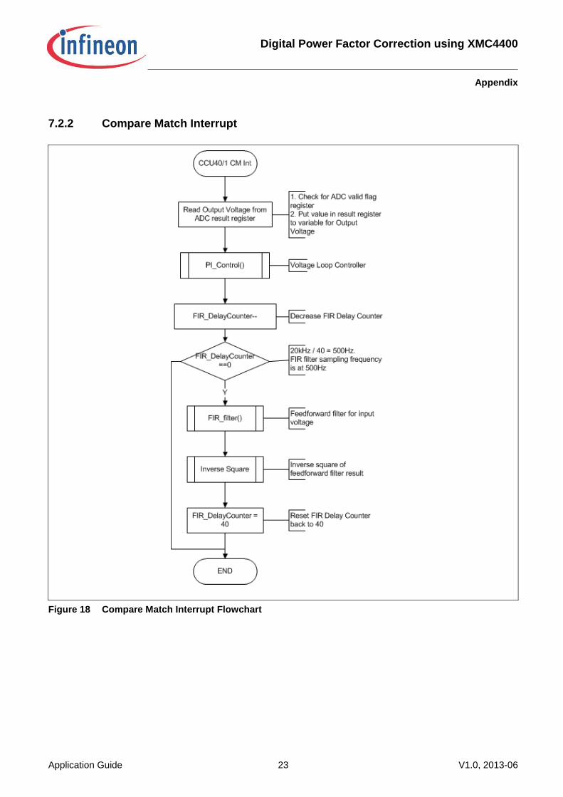
7.2.2 Compare Match Interrupt
Figure 18 Compare Match Interrupt Flowchart
Digital Power Factor Correction using XMC4400
Appendix
Application Guide 24 V1.0, 2013-06
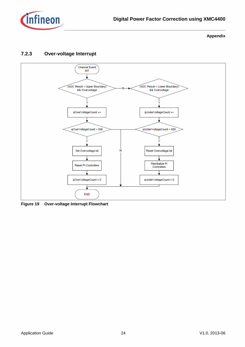
7.2.3 Over-voltage Interrupt
Figure 19 Over-voltage Interrupt Flowchart

w w w . i n f i n e o n . c o m
Published by Infineon Technologies AG