digital logic designdigitallogicdesign.weebly.com/uploads/1/3/5/4/13541180/lecture_1.pdf ·...
TRANSCRIPT

DIGITAL LOGIC DESIGN (ELE 241)
Ali Mustafa Lecture # 01

Instructor Introduction
Ali Mustafa
BSC Computer Engineering
(Comsats Pakistan)
MS Mobile Communication
(University of Bradford England)
Worked as
GSM Engineer in I-Track
Telecom Engineer in UFONE
WiMAX Engineer in NUST
Get in Touch with Instructor
Class Meeting Times & Locations: Monday 10:00 am – 11:30 am
Wed 11:30 am – 1:00 pm
Instructor Name: Ali Mustafa
Instructor Telephone: 057-9316329-137
Instructor E-Mail Address: [email protected]
Instructor Office Hours:
Tuesday 9:00 am -4:30 pm
Instructor Office Location* : Engineers Room – DLD Lab EE Department
(* Will confirm later)

Subject Information
SUBJECT CODE & NAME: ELE 241, DLD
CREDIT HRS : 03
CONTACT HRS : 03 per week
TEXT BOOK : Digital Design (4th Edition)
M. Morris Mano, Michael D. Ciletti
REFERANCE BOOK : Digital Fundamentals (9th Edition)
Floyd

Objectives
Understand theory of operation for most of digital
electronic devices.
Analyzing how can a digital computer perform the
complex operations based on simply manipulating
bits (zeros and ones).
Design of digital logic systems.

Topics to be covered
Digital Systems and Binary Systems
Boolean Algebra and Logic Gates
Gate-Level Minimization
Combinational Logic
Synchronous Sequential Logic
Registers And Counters
Digital Integrated Circuits

Evaluation Plan
The Course assessment will be made up of the
following four components;
1. Sessionals --- 25%
2. Quizzes --- 15%
3. Assignments --- 10%
4. Final Examination --- 50%

Students are responsible for:
1. Attendance. If a student misses more than 3 class sessions they may be dropped.
2. Arriving to each class on time. Late comers are disruptive to the class.
3. Letting the instructor know if you require any special considerations such as special seating.
4. Turning off all cell phones while in class.
5. Conducting themselves in a professional manner; refraining from talking in class except as part of a classroom discussion or to ask a question.

Students are responsible for:
6. Knowing and adhering to due dates for all
assignments, mid-term and final exam.
7. Taking or acquiring class notes.
8. Knowing COMSATS policies and procedures, This
includes plagiarism and cheating.
9. Letting the instructor know if you are having
difficulty with any part of the course. Special time
can be arranged for individual assistance.

Student Introduction
Welcome to COMSATS
Welcome to this Course
Brief Introduction
About yourself
Last semester experience
Suggestions
NOTE: Medium of communication will be English in the class.
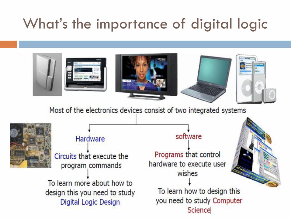
What’s the importance of digital logic

Flash back on Digital logic history
1850: George Boole invents Boolean algebra.
1946: ENIAC: 1s telectronic computer
18,000 vacuum tubes
5,000 operations per second
1,000 square feet
It really cost a lot of power to turn on the switch?

And it went on………
1947: Shockley, Brittain, and Bardeen invent the transistor
replaces vacuum tubes
enable integration of multiple devices into one package
1955: TRADIC: AT&T Bell Laboratories announced the first fully transistorized
1958: 1stIntegrated Circuit
1972: Intel’s 8088 1stmicroprocessor.

Applications of logic design
Conventional computer design
CPUs, busses, peripherals
Networking and communications
Phones, modems, routers
Embedded products
Cars
Toys
Appliances
Entertainment devices, e.g. MP3 players, PS3, and many others

Classification of Signals/Systems
They are classify into two categories
Analog Signal:
They have infinite number of different magnitudes or values.
They varies continuously with time.
Digital Signal:
A signal is known as digitised if it has finite number of
magnitudes.

Analog Signals
An analog or analogue signal is any variable
signal continuous in both time and amplitude.
e.g. Sound
ExampleThey have infinite number of values
They are continuous in nature
Source of signals can be signal generator
Sine wave is an example

Digital Signals
Digital describes any system based on discontinuous
data or events.
Computers are digital machines because at their most
basic level they can distinguish between just two
values, 0 and 1, or off and on.
Number of values can be finite (2,8,16)
Nature of signals are discrete
Source can be computer or A to D converter
Binary signal is an example

Advantages of Analog signals
They are used in
Filter design
Amplifier circuits
Signal Generators
Motor Speed Controller

Drawback of Analog System
Less accurate
Less reliable
Memory/Storage is an issue
Performance changes as temperature varies
Distortion and noise

Advantages of Digital System
It manipulates discrete element of information such
as decimal digits or alphabets.
Signal in digital system represented by a binary
digit called a bit.
Discrete elements of information are represented by
a group of bits called Binary Codes.
They are reliable,flexible,programmable and
updating technology.

Basic Digital Devices
Logic Gates
Combinational circuits
Sequential circuits
ICs

Logic Gates
Digital Logic Gates are the basic unit to build any
digital circuit.
It operates on a number of binary inputs to perform
a logical function.
There are different types of gates available ,e.g
AND,OR,NOT,NAND,EX-OR,NOR

Combinational Circuits
When number of logical gates are connected
together to produce specified output by
combination of input variables.
It has no memory element.
Combinational Logic Circuit N Inputs M Outputs

Sequential Circuits
The circuit in which digital outputs are required to
be generated in accordance with the specified
sequence.
It has the memory interface (Flip Flop)
Combinational
Circuit
Memory Element Input
Output

Integrated IC
For complex circuits which involves number of
gates,IC is used.
Small Scale IC (SSI) 20 gates circuit
Medium Scale IC(MSI) 20-200
Large Scale IC(LSI) 200 – 200,000
Very Large Scale IC(VLSI) 1,000,000

Binary Logic
Logic is defined as a statement which is true ,if
some condition is satisfied or vice versa.
Binary logic has two levels
High (1)
Low (0)
Lamp
OFF , LOW (Logic 0)
Negative
ON , High (Logic 1)
Positive

Negative & Positive Logic
Electrical Signals [ voltages or currents ] that exist throughout a digital system is in either of two recognizable values [ logic 1 or logic 0 ]
Logic 0 and 1 can be represented by another way of logic
Positive Logic Logic 0 (Low) 0V
Logic 1 (High ) +5V
Negative Logic Logic 0 (Low) +5V
Logic 1 (High ) 0V

Introduction to Number System
Number system is basis for counting various items.
Modern computer operated in binary number
system.
Decimal,Octal,Hexa,BCD represents more bits in a
binary numbers in a compressed form.
Base/Radix of the number systems are 2,8,10,16
Base decides the total no of digits available in a
system E.g Binary Base 2 0 or 1

Introduction to Number System
1st digit is always zero and last digit is always base
-1.
Each digit position represent different multiples of
base.
3 4 9 . 2 5
Radix Point
Power 0 Power1 Power 2 Power -1 Power -2

Different Number Systems
Decimal
Binary
Octal
HexaDecimal
Conversion of Number System
Examples