digital ecosystems: challenges and proposed solutions
TRANSCRIPT

A. R. Razavi, P. Krause and S. Moschoyiannis Department of Computing, University of Surrey, UK
Abstract: Current research and development in ICT has opened new opportunities
and threats for both large corporations and SMEs alike. Many SMEs see the new Digital Ecosystem as a new open frontier where they can enter, innovate and compete with large corporations on an equal footing. This paper examines the role of the large corporations (the keystones) in the digital ecosystem and presents solutions about the emergence of two major problems that if left unanswered will result in the creation of major entry barriers for SMEs. Our proposed distributed coordination and high connectivity between SMEs can provide a more appropriate business environment for fair competition and collaboration.
Key Terms: long-running transactions, lock schemes, concurrency control, partial
results, scale-free networks, connectivity, Virtual Super Peers, reconfiguration, digital ecosystems, keystones, digital economy, service innovation.
INTRODUCTION The aim of this chapter is to introduce the concept of Digital Ecosystems, analyse the challenges, and then discuss some of the proposed solutions and ongoing research in this domain. Our main thesis is that current digital infrastructures for collaborative working introduce serious barriers to adoption of, and innovation within, the digital economy by Small to Medium-sized Enterprises (SMEs) and micro-enterprises. Using the ecosystem metaphor, this implies that currently Digital Ecosystems favour “keystone species”. Yet it is the long tail of less-dominant “species” that typically provides the pool of innovation and response diversity (in cases of external shocks to the system) in healthy ecosystems. To address this bias, we will argue that advanced Peer-to-Peer architectures are critical in order to fully realise the potential of the World Wide Web to collaborative business and knowledge sharing. We will discuss these risks in more detail in the next section. Since 2002, the EU funded DBE and, subsequently, OPAALS projects have been developing approaches to addressing these risks and empowering SMEs in the digital economy. Following the review section, we will then progress with discussion of the architecture, formal framework, detailed design and implementation of a digital infrastructure that supports collaboration and service innovation amongst enterprises, without violating the “local autonomy” of the participants.
DIGITAL ECOSYSTEM: A SHORT HISTORICAL REVIEW (FROM METAPHOR TO REALITY) The concept of “business ecosystem” appears to have been first introduced in a well-cited article of James F. Moore in 1993 (“Predators and Prey: The New Ecology of Competition” (Moore, 1993)), where he compared the business environment to an ecological system. The metaphor “business ecosystem” is used to describe the business environment as an economic community, which “is supported by a foundation of interacting organizations and individuals – the organisms of the
Digital Ecosystems: challenges and proposed solutions

2
business world” (Moore, 1993). This comparison of economy to biology has been seen as extremely relevant and useful, not only because it improves our understanding of the roles and interconnectedness of various actors in the business ecosystem, but also because it explicates the increasing connectivity and complexity of these systems. Of course, one can consider an economy to be a national business ecosystem (Rothschild, 1995) composed of many smaller systems, all of which are directly or indirectly interconnected. What many call an industry can now be considered to be either an ecosystem in itself or part of a larger one. These business ecosystems are populated by (some loosely) interconnected organisms: businesses, consumers, the government and other stakeholders. As far as the business population of each business ecosystem is concerned, the majority is composed of Small and Medium size Enterprises (SMEs) along with a few large ones, the so-called keystones. Marco Iansiti and Roy Levin compare the role of these keystone companies to those of keystone species in nature (Iansiti & Levien, 2004). They argue that we live in an interconnected world, the landscape of which is made of a network of networks, with keystones at the hubs and niche players surrounding the hubs. In nature a Keystone species is defined as “a species whose effect is large and disproportionately large relative to its abundance” (Power et al., 1996). It is also argued that Keystones help in determining or regulating the number and type of other species in their communities. The keystone concept has been adopted in both computer and business literature but recently the correctness of the analogy has been questioned. As an example, Payton et al. (Payton, Fenner, & Lee, 2002) provides some of these arguments on the concept in its original context, namely the definition and role of keystones in ecology. Technological innovations have always led to the creation of new companies by entrepreneurs who have tried to take advantage of those innovations to create a competitive advantage for themselves in the marketplace; which in turn necessitated the adaptation of those innovations by the older established companies. The Industrial age and Business Ecosystems Until relatively recently, the rate of diffusion and adaption of new technologies was rather slow. Lack of speedy communication was one of the reasons behind this glacial diffusion rate. For example, new machines were invented and used in one part of the world without being introduced and used in other parts. A good example of this is the printing press, which was invented in China a few hundred years prior to its “re-invention” in Germany in 1439. However, the industrial revolution (1760-1840) (Iansiti & Levien, 2004) reduced the distance between the continents. The improvements in steam engines (steam locomotives, 1804), invention of telegraph in 1830s and later the telephone in the 1860s effectively reduced distances between towns, countries and continents. This reduction in distance also opened new markets, allowing manufacturers and producers to increase production capacity, which in turn led to increasing size of these companies. Indeed the origins of the modern diversified corporations can be traced back to the creation of large corporations at the beginning of the last century; when mass-production (brought about by innovations in work methods and mechanical automation) allowed many companies to grow rapidly and prosper at a rate that had never been seen before in history. Companies such as Ford, General Motors, Standard

3
Oil Company and others grew from small businesses to large corporations (keystones), whose turnover matched the GNP of many small nations. In this era competition, by and large, was seen as “dominate or absorb” with one exception: the creation of cartels. “Price competition among large-scale rivals proved mutually destructive to profits and after a brief period of cut-throat competition, business enterprise turned to cartels, trusts and other monopolistic forms of organisation designed to eliminate price competition” (Dillard, 1967). Here the theories of Cournot (Cournot, 1960) (monopoly, duopoly, and oligopoly), first published in 1838, were put to work. This allowed the owners, the so-called “robber barons” (Josephson, 1962), to concentrate on increasing internal efficiency of their organisations. Part of this internal efficiency was achieved by focusing on economies of scale, i.e. to produce a product faster, better and cheaper than competitors, using mass-production (changes in the supply side). As the competition intensified and marketing and customer demand became more important, these companies began to change their focus to economies of scope (Chandler, 1990); that is producing “different products” faster, better and cheaper. But by entering to the Information age, the rules and playground has changed substantially. Information age and Digital Business Ecosystems A Digital Business Ecosystem or Innovation Ecosystem results from the structurally coupled and co-evolving digital ecosystem and business ecosystem (Nachira, 2002) and (Nachira, Dini, Nicolai, Louarn, & Leon, 2007). A network of digital ecosystems will offer opportunities of participation in the global economy to SMEs and to less developed or remote areas. These new forms of dynamic business interactions and global co-operation among organisations and business communities, enabled by digital ecosystem technologies, are deemed to foster local economic growth. The role of keystones has dramatically changed from the industrial age to the information age. Technological evolutions usually give birth to new industries where start-ups and existing SMEs, because of their size (agility), typically enter first, becoming the first movers. First movers generally have the advantage of registering patents, establishing brand names and changing the economics of the market; ultimately making it difficult for others to enter and compete and so on. In young industries, first movers have the ability to, in a very short time, become industry leaders or keystones. We have seen this with Microsoft and personal computer operating systems. In the connected digital world, this first mover advantage has been very rewarding for these companies. First movers have managed to become strong hubs with many links, becoming almost impervious to competition from smaller actors. By considering the Internet as a provided network for digital ecosystems, the network can be described as a network that has no predetermined structure and expands in a random fashion. New nodes (computers) constantly connect and disconnect themselves to the network via links (vertices) to other computers. Studies (Barabási & Albert, 1999), (Barabási, Albert, & Jeong, 2000) have shown that the topology of this network follows a power-law distribution; which means that often a few nodes evolve in such a way to attract a large number of links while many nodes continue to exist with only a few links. This is especially true for the World Wide Web (WWW) where page links act as links to other pages and hence internet sites. This gives those nodes with large number of links, and companies that own them, a disproportionate power in the network; First movers have managed early-on to become large hubs.

4
SMEs in this sector have very little chance of becoming hubs. The entry barriers in this sector are getting higher and higher. If by chance or design an SME manages to acquire a number of links (e.g., Alibaba.com in China), it is bought (Alibaba was acquired by Yahoo) and integrated into the existing hub. In such an environment, first movers take advantage of their position and try to establish themselves as the industry leaders. As such they constantly try to either set the industry standard or change the proposed standards to their own advantage. So here we see two distinct problems: the first being the structure of the networks where hubs try to dominate1 and the second being the question of standards being set for the creation of applications that will be running on those networks2. The other challenge is the coordination of information systems of different enterprises over the net. The ideal solution, as has been proposed and pursued, is to establish mechanisms that allow different businesses with different practices, equipment and technologies to seamlessly and effectively communicate with each other. One of the solutions that is being widely explored by major players and other organisations has been Service Oriented Architecture (SOA). But note that this is more of a mind-set or a development philosophy than anything else. As such the concept has been around for a number of years and did not become interesting for major software developers and vendors until the emergence of the concept of a Web Service (WS). A WS is defined as “a software system designed to support interoperable machine-to-machine interaction over a network” (Booth et al., 2004). The whole concept of SOA revolves around services and loose coupling (Singh & Huhns, 2005). “The goal of SOA is to allow fairly large chunks of functionality to be strung together to form ad hoc applications which are built almost entirely from existing software services. The larger the chunks, the fewer the interface points required to implement any given set of functionality; however, very large chunks of functionality may not be granular enough to be easily reused. Each interface brings with it some amount of processing overhead, so there is a performance consideration in choosing the granularity of services. The great promise of SOA is that the marginal cost of creating the n-th application is zero, as all of the software required already exists to satisfy the requirements of other applications. Only orchestration is required to produce a new application.” (“Service-oriented architecture - Wikipedia, the free encyclopedia”). However, currently there is a foundational problem. Both of the currently extant coordination protocols for business transactions, violate loose coupling on one side and offer just one pattern of behaviour (this is important as it relates to clarifying the completion protocol in a transaction and determining the recovery method in respect to that protocol (Razavi, Krause, & Moschoyiannis, 2006)) for participants of transactions, on the other (Vogt, Zambrovski, Gruschko, Furniss, & Green, 2005). This tight coupling results in the participants (e.g. SMEs) losing their local autonomy
1 The power of these hubs is so strong that even large companies with sufficient financial resources and know-how such as Microsoft have trouble competing effectively in these segments. Similarly, as Microsoft used its size and financial resources (derived from its operating system) to spread its wings and expand into different segments, these hubs are also trying to establish themselves as Goliaths in other areas. 2 Example of this is variety of protocols and standards on security, resource sharing, identity, etc which in several cases are not compatible or are in contrast with each other.

5
(their local state of business will be visible to the coordinator). At the same time the pattern of behaviour supported by the coordinator framework (do-compensate (Furnis & Green, 2005)), forces participants to apply specific methods of fault recovery during a transaction failure (Razavi, Moschoyiannis, & Krause, 2007), (Razavi, Moschoyiannis, & Krause, 2007c). This not only enforces a specific problem solving method in the event of a failure (which is known by the companies supporting the protocols) but also imposes the responsibility of sorting the failure out to participants. The other crucial concerns related to digital ecosystems have been raised by a new generation of applications on the Internet, the so-called Web 2.0 (OREILLY, 2005). Apart from unclear security and safety measures, digital ecosystems are extending their business models behind the boundary of conventional business environments. As a result, the coordination model is freely granted full access to an individual’s social network. Despite the currently formative business plans of these large organisations, the potential side effects of such violations of privacy offer considerable benefits to those organisations, with minimal benefit to the individuals (some of the general issues have been discussed in (Barnes, 2006)). These problems provide significant barriers to the inclusion of SMEs and micro-enterprises in the digital economy. They also act as major barriers to service innovation. We will now explore our proposed solutions to these problems.
DIGITAL ECOSYSTEMS: DISTRIBUTED AGENTS As discussed in the previous section, current protocols in transaction frameworks targeted at supporting business activities between networked organizations provide a centralized solution, which not only violates the primary concept of SOC (loose-coupling) but also does not cover all aspects of their business activities. This creates tight dependencies which are susceptible to the risk that comes with a single point of failure in the framework. In contrast, our purposed model, from the very beginning and early prototypes, advocates a fully distributed solution and relies on the P2P interactions between the platforms (here, participants) (Razavi et al., 2006), (Razavi, Moschoyiannis, & Krause, 2007a). As the kernel of each platform, we have designed a software agent which is responsible for coordinating the participant’s business activities (transactions). This local agent also archives the information related to these activities (corresponding VPTNs) and improves the general connectivity of the network (its digital ecosystem), and in doing so it contributes to the so-called network growth (Razavi et al., 2007a). This is an important aspect when it comes to sustainability, especially in a fully distributed solution. This leads up to the main definition of a digital ecosystem (recall section II) which is represented in Fig 1, highlighting the fact that there should be no centralized point of command and control in a digital ecosystem.

6
Fig. 1 Local Agent for each participant
Fig. 1 shows the structure of the local software agent of each participant. The ‘local coordinator’ component coordinates the service requests to and from the local platform. In other words, it deploys services of the platform, coordinates the transactions and archives their information in the ‘local service repository’. In this way, all participants of a transaction will keep the archived information of the transaction. The ‘local web service informer’ component updates any changes of local services in the ‘local service repository’ and relevant participants can be notified of the changes through the ‘web service promoter’. The links to other participants will be kept in the ‘global service repository’. Note that at this stage, participants of different VPTNs are connected to each other [in (Razavi et al., 2007a) this is called the birth stage of the underlying network]. For reducing the possibility of failures and increasing the network stability (Section V), the network connectivity, i.e. the number of links to other participants, may change. These changes will be done by two components; the ‘web service information investor’, for updating new links to the global repository and the ‘web service promoter’, for promoting new links to other participants [in (Razavi et al., 2007a) this is referred to as the growth stage]. Fig 2 shows a diagram, where four agents are communicating; Agent A and B are Participating in a Transaction (Section IV) and Agent D and C are involved in the network growth for increasing the connectivity (Section V).

7
Fig. 2 Local Agents Communication Diagram
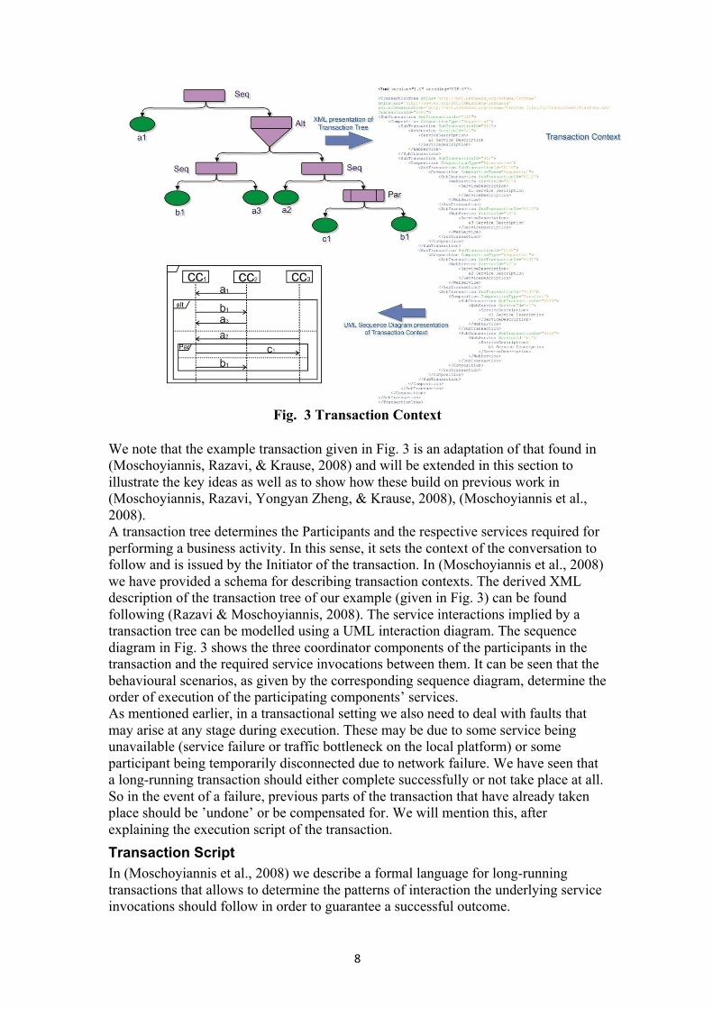
DIGITAL ECOSYSTEMS: LOCAL COORDINATION Transaction Context In previous work (Razavi et al., 2007c) we have described the use of a tree structure to represent transactions that involve the execution of services. This allows us to capture nested sub-transactions - the internal actions that need to take place in the course of execution of the transaction. To respect the loose-coupling of the underlying services, which is a basic premise of Service-Oriented Computing (SOC) (Papazoglou, 2003), (Papazoglou & Georgakopoulos, 2003), each participant provides its services and requests services of others through a coordinator component. Its purpose is to manage the communication between the different participants’ platforms and the deployment of the corresponding services. Drawing upon the latest work on the SOC computing paradigm (Papazoglou, Traverso, Dustdar, Leymann, & Kramer, 2006), we have considered different composition types which allow for various modes of service interaction in our model. Fig. 3 shows a transaction tree with five basic services - a1, a2 and a3 of a local platform with coordinator component CC1, b1 of CC2, and c1 of CC3 - whose order of execution is determined by the corresponding composition types [transaction context symbols are based on the notation that first appeared in (Haghjoo & Papazoglou, 1992)].
8
Fig. 3 Transaction Context
We note that the example transaction given in Fig. 3 is an adaptation of that found in (Moschoyiannis, Razavi, & Krause, 2008) and will be extended in this section to illustrate the key ideas as well as to show how these build on previous work in (Moschoyiannis, Razavi, Yongyan Zheng, & Krause, 2008), (Moschoyiannis et al., 2008). A transaction tree determines the Participants and the respective services required for performing a business activity. In this sense, it sets the context of the conversation to follow and is issued by the Initiator of the transaction. In (Moschoyiannis et al., 2008) we have provided a schema for describing transaction contexts. The derived XML description of the transaction tree of our example (given in Fig. 3) can be found following (Razavi & Moschoyiannis, 2008). The service interactions implied by a transaction tree can be modelled using a UML interaction diagram. The sequence diagram in Fig. 3 shows the three coordinator components of the participants in the transaction and the required service invocations between them. It can be seen that the behavioural scenarios, as given by the corresponding sequence diagram, determine the order of execution of the participating components’ services. As mentioned earlier, in a transactional setting we also need to deal with faults that may arise at any stage during execution. These may be due to some service being unavailable (service failure or traffic bottleneck on the local platform) or some participant being temporarily disconnected due to network failure. We have seen that a long-running transaction should either complete successfully or not take place at all. So in the event of a failure, previous parts of the transaction that have already taken place should be ’undone’ or be compensated for. We will mention this, after explaining the execution script of the transaction. Transaction Script In (Moschoyiannis et al., 2008) we describe a formal language for long-running transactions that allows to determine the patterns of interaction the underlying service invocations should follow in order to guarantee a successful outcome.

9
Fig. 4 Transaction Script A transaction T is associated with a set of coordinator components C and a set of actions M. Our interest is in the observable events on the coordinator components and thus actions can be understood as service invocations between the participating components, as shown for example in the scenario of Fig. 4. Hence, each component in C is associated with a set of actions which correspond to deploying (its own) or requesting (others') services. If we denote this set by µ (i), for each i∈C, the previous sentence can be expressed more formally by defining the function µ : C→P(M)3 and requiring that
Ci∈
µ (i) ⊆M.
As can be seen in Fig. 3, a transaction has a number of activation or access points, namely the interfaces of the coordinator components participating in the interaction. Thus, instead of modelling the behaviour of a transaction by a sequential process, which would generate a trace of a single access point, we consider a number of such sequences, one for each component, at the same time. This draws upon Shields' vector languages (Shields, 1997) and leads to the definition of the so-called transaction vectors. Transaction vectors. Let T be a transaction. We define VT to be the set of all functions v: C→M* such that v(i) µ∈ (i)*. By µ (i)* we denote the set of finite sequences over µ (i). Mathematically, the set VT is the Cartesian product of the sets µ (i)*, for each i. Effectively, transaction vectors are n-tuples of sequences where each coordinate corresponds to a coordinator component in the transaction (hence, n is the number of leaves) and contains a finite 3 P(M) denoting the power set, or set of all possible subsets of M.

10
sequence of actions that have occurred on (coordinator of) that component. When an action occurs in the transaction, that is to say when a service is called on a coordinator component, it appears on a new transaction vector and at the appropriate coordinate. The idea is that the particular subset of transaction vectors, for a given transaction, expresses the ordering constraints necessary in the corresponding orchestration of the underlying services. For instance, in the transaction of Fig. 4, following action a1, there is a choice between b1 on the coordinator component CC2 and a2 on CC1. Whenever b1 happens, it is followed by a3 on component CC1 whereas a2 is followed by c1 and b1 which happen concurrently on CC3 and CC2, respectively. Notice that the order structure in case of concurrent actions (as in b1 and c1 here) exhibits the characteristic structure of a finite lattice: A lattice is simply a mathematical way of representing partial orders in some set of entities (actions in our case). This means that after the behaviour described by vector u = (a1a2, Λ, Λ) both independent action vectors α1 = (Λ, b1, Λ) and α2 = (Λ, Λ, c1) take place, resulting in the behaviour described by vector v = (a1a2, b1, c1), which is their least upper bound (i.e. no other action can be “squeezed in” before v). The additional structure provided by the notion of independence allows to go round the lozenge once and always end up with the behaviour in which both actions happened concurrently (this can be seen in (Moschoyiannis et al., 2008)). As we will see in the next subsection, this also applies to going backwards and allows to compensate concurrently for concurrent forward actions. The order structure of the transaction language determines the pattern the underlying service interactions between the coordinator components in the transaction should follow. Starting with the empty vector, and following the pattern of Fig. 3, each subsequent action (or concurrent actions) take place in going forward until the transaction as a whole terminates successfully. In (Moschoyiannis et al., 2008), we have provided a schema for deriving the XML description of the order structure of a transaction language. These so-called transaction scripts describe the interactions between different coordinator components (recall Fig. 2) and determine the order in which the underlying services need to be deployed. Fig. 4 shows the transaction script generated from the vector-based behavioural description of the transaction in our approach Transaction scripts reflect the corresponding transaction languages and hence describe the dependencies between services of different participants’ coordinator components, in terms of the orderings of the underlying service invocations. This means that when the scripts are parsed they provide the full transaction history, resulting from the actual deployment of the transaction, but based on the associated formal semantics of the transaction. The XML schemas and further details on transaction scripts can be found (downloaded) following (Razavi & Moschoyiannis, 2008). Execution History So far we have described the use of transaction languages in expressing the forward behaviour of a transaction in terms of the orderings of the underlying service executions, and these can be analysed prior to deployment in determining the set of allowed sequences of actions. In our approach, the transaction history is captured in the order structure of the corresponding transaction language which is used to express forward behaviour and is reflected in the derived transaction scripts. As shown in Fig. 4 a transaction language which includes alternative actions will have different allowed execution paths. These start from the empty vector and lead to (one of) the largest vectors in the language. The largest vectors describe maximal behaviour of the

11
transaction, in the sense that they do not describe an earlier part of behaviour than any other vector does. In the transaction language of Fig. 4 there are two maximal vectors, namely v1 = (a1a3, b1, Λ ) and v2 = (a1a2, b1, c1). This means that one allowed sequence of execution is a1 → b1 → a3 and the other is a1 → a2 → (b1 concurrently with c1). Note that both allowed sequences end up in a maximal vector which corresponds to the behaviour exhibited when the transaction executes successfully until it terminates. Thus, in both cases the transaction produces a consistent state. In other words, transaction consistency is attained by reaching a maximal vector in the transaction language. The existence of two maximal transaction vectors in this case means that there are two alternative execution traces that lead to successful completion of the transaction.
Fig. 5 Execution History
When the transaction is actually deployed, then of course only one of the allowed sequences of actions can occur. In our example, this would depend on how the choice between a2 and b1, after a1 has occurred, is resolved. Fig. 5 shows the case where a2 occurred after a1, and hence the right branch of the Hasse diagram with the transaction language was actually deployed. It can be seen that each vector in turn is obtained by coordinate-wise concatenation with the appropriate action vector, according to the allowed sequence of actions along the particular execution path. This distinction between the set of all allowed sequences of actions and the allowed sequence of actions that actually takes place when the transaction is deployed is important when considering compensations. Naturally, when a failure makes further progress impossible, we would only want to compensate for actions that actually happened up to that point and not for every possible action in the transaction. We will refer to the actual path of execution during a run of the transaction as the execution history of the particular deployment of the transaction. In Fig. 5 it appears there are two execution histories but these are the result of concurrency (between b1 and c1) and therefore, they are equivalent. This is because the series of concatenations with action vectors differ only in the order of the independent action vectors α1 = (Λ, b1, Λ) and α2 = (Λ, Λ, c1), and consequently they correspond to the same allowed sequence of actions. This notion of independence is what allows us to identify equivalent behaviours in the presence of concurrency, something that is not possible when adopting an interleaving model, as done in (Butler, Hoare, & Ferreira). The benefit of being able to identify equivalent execution histories can perhaps be seen most clearly when it comes to compensation in transaction recovery, where as we will see it is only required to compensate once for all equivalent execution histories.

12
Coordination and Transaction Failure In this part we extend our approach to coordinating long-running transactions to handle compensations. This is to address occasions where some failure happens mid-way through execution in which case we need to have a way to express compensating sequences of actions that need to take place in going ‘backwards’ while effectively undoing all previously successful forward actions. The operation per coordinator is called right-cancellation, which it is equivalent to calling a cancelation for a service [a formal definition of this can be found in (Moschoyiannis et al., 2008) and (Razavi, Moschoyiannis, & Krause, 2007b)]. Fig. 6 shows the case where a failure occurs after service a2 of component CC2 has been invoked. This means that it is no longer possible for the transaction to produce a consistent state by reaching the maximal vector (a1a2, b1, c1), as dictated by the allowed sequence of actions in its execution history. Consequently, the transaction needs to be recovered and this implies returning to the (consistent) state the system was in before the transaction started.
Fig. 6 Transaction life-cycle
We have seen how right-cancellation can be applied to generate compensating sequences of actions for the full recovery of a transaction. Full recovery however, can be costly in terms of resources, delays, business relations and so on. Additionally, in a highly transactional environment dependencies may also exist across transactions so the effect of a recovered transaction may be magnified. For this reason it is desirable to avoid full recovery wherever possible. One way to do this is to design transactions with a number of alternative scenarios of execution; in other words, allow for multiple execution histories in the corresponding transaction script. In such cases, our approach comes with the provision for forward recovery which is a mechanism for avoiding full recovery. The aim is during compensation to explore whether there is any possibility for successfully terminating the transaction following a different execution history to the one originally deployed, instead of compensating for the whole execution history.

13
This is possible in our approach because all the execution histories are captured in the transaction language. Hence, in recovering a given execution history which failed, after the next forward action(s) is compensated for we check whether the resulting vector is also part of a different execution history. If this is the case, then we attempt to go forward by performing the execution in accordance with the allowed sequence of actions in that alternative execution history. As shown in the green box, Fig. 6, in going backwards, and while cancelling out one action (or a set of concurrent actions) at a time, we look each time whether there is an alternative path from the vector we arrived on (after applying the compensating action(s)) leading to a maximal vector (successful outcome). For those familiar with logic programming, this is directly analogous to the use of backtracking when searching for a successful solution to a goal. Data inconsistency in business transactions According to the definition of (Gray & Reuter, 1993), a transaction that is started when a system is in a consistent state may make the state temporarily inconsistent, but it must terminate by producing a new consistent state. In conventional transactions, this has been provided by applying isolation theorems [This maintains the illusion that each transaction runs in Isolation. The conventional mechanism for doing so is to use an S/X (Share/eXclusive) Lock, (Bernstein, Hadzilacos, & Goodman, 1987) and (Gray & Reuter, 1993)]. Violation of the isolation property is related to various dependency cycles. As with conventional transactions, cyclic dependencies in long-running transactions are categorized into three generic forms [full details can be found in most transactional or database books such as (Date, 2003) or (Gray & Reuter, 1993)];
• Lost updates: The first sub-transaction’s write (deploying the data) is overwritten by the second sub-transaction which uses write based on the initial value of the object.
• Dirty read: A sub-transaction reads an object which has been written before by another uncommitted sub-transaction which also writes to it again after the read action. This means the first sub-transaction may find inconsistency in the object.
• Unrepeatable read: A sub-transaction reads an object that is then read by another sub-transaction which also writes to it after its read action and commits. Meanwhile, the first sub-transaction reads the object again, and may find an inconsistency in the object.
These show cycles in access to objects, called a wormhole, which we explain later in this section. First we should to formalize the long-running transaction’s execution according to its accessing of objects. In defining an execution of a long-running transaction we use the standard term schedule. A schedule of a long-running transaction is any sequence-preserving merge of the actions (i.e. reading, writing, aborting, committing) of a set of sub-transactions into a single sequence for the set of sub-transactions and is denoted by:
Each step of the history <st,a,o> is an action a by sub-transaction st on object o. By
analysing a history, we can capture all dependencies (WRITE→WRITE, WRITE→READ and READ→WRITE) into a dependency relation DEP[H], where two sub-transactions are dependent if they engage in actions on a common version of an object.

14
Wormhole Theorem
This theorem is a well-known theorem in isolation theory. In what follows we outline how it can be adapted to determine wormhole-free transactions of the kind considered in our approach, i.e. long-running transactions. Hence, before using the classic theorem and its proof (Gray & Reuter, 1993) we introduce the equivalent concept and notation in long-running transactions, and then adapt the proof to long-running transactions. The dependencies in the history of a long-running transaction can define a time ordering of the sub-transactions. Conventionally this ordering is signified by the relation <<<H , (or simply by <<< when the history is clear from context), and is the transitive closure of the dependency relation, DEP[H]. <<<H is the smallest relation satisfying:
In terms of the dependency graph, we can say that ST<<<ST’ if there is a path in
the dependency graph from sub-transaction ST to sub-transaction ST’. The <<< ordering defines the set of all sub-transactions that run before or after ST;
If ST is fully isolated (i.e., it is the only sub-transaction, or it’s read and write
objects are not accessed by any other sub-transactions), then its BEFORE and AFTER sets are empty, and it can be scheduled in any way. When a sub-transaction is both after and before another distinct sub-transaction (ST here), it is called wormhole transaction (ST’ here):
It is not hard to see that serial histories do not have wormholes - in a serial history,
all the actions of one transaction precede the actions of another, i.e. the first cannot depend on the outputs of the second.
Based on the wormhole theorem, a history is isolated if, and only if it has no wormhole sub-transactions (Gray & Reuter, 1993). On the other hand, the isolated histories have the unique property of having no wormholes. The theorem dictates that a history that is not isolated has at least one wormhole; ST<<<ST´<<<ST. (i.e. ST´ has critical dependencies on an uncommitted transaction).
In graphical terms we can say that if the dependency graph has a cycle in it, then the history is not equivalent to any serial history because some sub-transaction is both before and after another sub-transaction. A wormhole in a particular history is a sub-transaction pair in which ST ran before ST´ which ran before ST. In the next section, we propose a mechanism for avoiding wormholes using our distributed coordinators.
Internal dependencies We have shown that by avoiding wormholes we can release results between sub-
transactions of a long-running transaction. In doing so, we use the dependency graph to trace released data items (objects) between each participant. This graph is updated

15
regularly and potential cycles (wormholes) can be detected in each step. As this graph captures dependencies between sub-transactions of a transaction we call it the Internal Dependency Graph (IDG).
For clarifying access-rights, inside of each participant we use a simple lock mechanism which is compatible with the conventional S/X Lock. The only difference with an S/X Lock is the UN-Lock mechanism. Since participants are executing a sub-transaction and the result can only be visible in that particular long-running transaction, instead of unlocking the data we introduce an internal lock I-Lock which unlocks the data items in the context of a particular transaction. This means the data item will only be available for other sub-transactions of the transaction, which are executing in other participants. As mentioned in the beginning of the section, the execution of a transaction will be performed by the ‘local coordinator’ of the participants. Fig 7 shows a simple example.
Fig. 7 Internal Dependency Diagram
Fig. 7 shows part of a long-running transaction, where a parallel composition
between services c1 and b1 has a data-dependency. We have assumed that service c1 is a service offered by participant P1 and service b1 is provided by participant P2. Based on the transaction context described in the beginning of this section, c1 and b1 can be deployed in the context of two sub-transactions (STc1 and STb1). When participant P1, deploys the service c1 the service creates a data-item K as the output (notice that P1 uses X-Lock for writing/creating the object) and sub-transaction STc1 commits and releases the result for other sub-transactions. To do this P1 uses I-Lock and a pre-request for the object while the IDG is created for the object. Our example illustrates the case where participant P2 needs the output of c1 (STc1). It can use the result, which has been released by I-Lock, and if there is a dependency between the two sub-transactions present in the corresponding IDG (STc1 <<< STb1), also shown in the figure, P2 uses S-Lock for reading K and proceeds to use it as the input in

16
service b1. Then P2 can again release it by using I-Lock on the data-item. Any subsequent usage of the data-item will be done by checking and updating the IDG. In this way, local coordinators can avoid any cycle (e.g., STc1 <<< STb1<<<...<<< STc1).
Partial results by using Conditional Commit As the life-cycle of long-running transactions is long, occasionally releasing results
between these transactions before their termination (commit/rollback) can be valuable for a digital ecosystem (Razavi et al., 2006), (Moschoyiannis et al., 2008) in covering a range of B2B scenarios. However, these ‘partial results’ can be costly - in case of abortion of the first long-running transaction we may face cascading abortion (Razavi et al., 2007b). Earlier in this chapter, we provided a mechanism for forward recovery and here we consider a similar approach in term of data-orientation (in case of abortion of the first transaction - this is further discussed in the next section). As the partial results are released before the actual commit of a long-running transaction, the mechanism for releasing them is called Conditional Commit. For conditional commit again we use a dependency graph in combination with the wormhole theorem. It is important to note that: • In the first place two long-running transactions had full invisibility towards each
other. therefore the released data-item from the first long-transaction has to be read by the second transaction
• As all the data-items are in the deployment level they will be created by the transaction in the first place. This means the first operation on a data-item for any long-running transaction will be a write (in fact, it can take place in one of its sub-transactions but this is the primary assumption of SOA).
Therefore in any conditional commit between transaction T1 and T2 there is a write
→read dependency and as the first transaction is not fully committed, any write operation can create a wormhole (T1<<<T2<<<T1 in terms of write →read →write). That is why after releasing the partial result the data-item will be read-only and this cannot change until the first transaction commits. Note also that the second transaction cannot commit before the first one does and as a result it will have a commit dependency. For addressing this limitation, we define a C-Lock for the conditional commit of partial results and the dependency graph for releasing these data-items is called External Dependency Graph (EDG). In addition to capturing the dependencies on particular data-items released between transactions, this graph also captures the commit dependency. By using the EDG the second transaction can not commit unless it receives a confirmation from the first transaction that it has committed. Figure 8 shows an example of using conditional commit.

17
Fig. 8 External Dependency Graph
In Fig. 8 transaction T1 releases the partial result (data-item K) to transaction T2.
As a result, the related External Dependency Graph (EDG) will be created by coordination of Participant P1 (one of T1’s participants which has done the last action on data-item K), and the graph is shared by P3 (one of T2’s participants which is going to do the first read operation on data-item K). The important point is that the C-Lock has been used for data-item K and the lock will be inherited by any participants which are going to use the data-item. In this way, the data-item will remain ‘Locked’ until the transaction, the one which has created the data-item (originator transaction; here, T1), commits. Meanwhile, in terms of abortion in the originator transaction, all dependent transactions should be rolled back. In the next section we describe the recovery procedure that needs to take place.
Recovery We start with the well-known ‘Rollback theorem’ and build our recovery procedure
around the concepts of degenerating the transactions and, of course, avoiding wormholes. In this respect we use the rollback theorem (A transaction that unlocks an exclusive lock and then does a ‘Rollback’ is not well-formed and is a potential wormhole, unless the transaction is degenerate). As the theorem is well known, we refer the interested reader to (Gray & Reuter, 1993) for the actual proof. The important point of the theorem is that we have to degenerate the transaction to effect rollback. For this purpose we can use the logs provided by the dependency graphs and trace them. The only caveat is that the digital ecosystem network is distributed and therefore there is no centralised synchronisation. This entails that there is a risk for wormholes.
Two phase recovery
For avoiding wormholes, we have designed the recovery procedure in line with our consistency model (logs/locks) for concurrency control. Overall, Recovery Management in combination with the concurrency control procedure runs in two phases:

18
• Preparation phase: This consists of sending a message (abort/restart) to the participants of all sub-transactions that puts them (and their data) into an isolated mode (preparing for recovery). This helps avoid any propagation of inconsistent data and possibility for creating wormhole during the actual rollback.
• Atomic Recovery Transaction routine: The recovery routine will be run as an atomic procedure that can rollback and cancel deployed services of sub-transactions by using correct data-items.
Both phases in recovery management rely strongly on tracing the corresponding dependency graphs. This is where the necessary information for finding the changes on data-items, in different participants, and to undo them and bring back the system to a consistent state. Figure 9 shows a sample scenario that extends that presented earlier in Fig 8.
Fig. 9 Recovery Procedure
According to Figure 9, a failure happens for T1 while participant P1 was trying to
execute the transaction. The participant P1 has to stop any further progress on T1 and uses its EDG and IDG for informing about the failure on T1. As shown in the figure, participant P3 uses some results from P1 for transaction T2, which means P3 has to start a similar procedure for transaction T2. This is the external dependency. Participant P3 now uses its IDG, which indicates that the participant P2 needs to be informed for stopping the potential execution of transaction T1 (in this case, it will be the sub-transaction STb1 of transaction T1). In fact, it has to inform any dependent transaction or sub-transactions by checking its related graphs to cater for all internal dependencies. Now for stopping the transaction progress (isolation of T1 affection) upon failure, we need an internal structure inside of the local coordinator.
DIGITAL ECOSYSTEMS: NETWORKING AND CONNECTIVITY Digital Ecosystem as a Network of Business participants
A digital ecosystem can be conceptualized as the result of several business transactions where each transaction creates a private network, the so-called Virtual Private Transaction Network (VPTN). Conceptually, we consider DU as all Digital Ecosystems, where TU is all of the possible transactions in these Ecosystems and PU all possible participants of the Ecosystem. Each transaction is the result of

19
compositions of services from several participants. This can be described by the pair (t, Pt), where Pt is the set of participants which are involved in a transaction t. The universe of digital ecosystems comprises all of the possible transactions and their participants and can be defined as:
We define a specific Digital Ecosystem DE, as a subset of DU, where all of its
participants, by engaging in its transactions, are connected. Each VPTN can be recognised by the transaction of its participants (t, Pt) where
In this paradigm, the maximum number of links which any one participant may
have is just the number of participants minus one (they do not link to themselves):
In our transaction model, coordination of the underlying services is distributed and addresses both the order and the data dependencies, and hence the actual number of links in a single transaction is always less than this:
EQ. 1 But based on the definition of a digital ecosystem, individual VPTNs can have
overlaps that make a connected network (participants can engage in multiple transactions). Therefore, nodes can be involved in several VPTNs and as a result, they will have additional links through this participation in different transactions. Studies show most business networks follow the power-law distribution degree (Barabási & Albert, 1999), which means that a very small number of nodes are involved in the majority of the transactions, and even in each transaction these “keystones” will have the maximum numbers of links.
Figure 13 shows a simple digital ecosystem, where ‘Participant 4’ and ‘Participant 3’, are involved in all of the VPTNs, and in each VPTN they get the majority of links.
Fig. 10 Digital Ecosystem of connected VPTNs
This has as a drawback that any problem in either ‘Participant 4’ or ‘Participant 3’
(or both) can cause serious disruptions in all the VPTNs. In addition, a simple failure on ‘Participant 4’ or ‘Participant 3’ can fragment the network, which means even if the involvement of ‘Participant 4’ or ‘Participant 3’ was restricted to alternative

20
service composition, still the transactions may not be executed. Moreover, since ‘Participant 4’ and ‘Participant 3’ have gotten this important role based solely on their business transactions they may not be the best candidate for providing connectivity for the network. In other words, their emergence as a highly connected node has been driven by the volume of transactions they take part in and no other factor. This raises the question of whether it is desirable for a digital business ecosystem to rely on very few nodes in general. Before addressing such aspects, we show how each VPTN will react to a failure and how it can be recovered, how the cost of failure can be reduced, and how full abortion of the transaction can be avoided. After that, we examine how the possibility for failures can be reduced all together. Link replication, and connectivity
Normally the connections (links) to other participants of the digital ecosystem have been established by the ‘global service repository’, where the addresses of other service providers (participants) and the description of their services have been kept. For inserting (or modifying) a new participant to the repository and its services, the ‘web service information investor’ component will be involved. For introducing the participant to another participant the ‘web service promoter’ will be used.
It can be seen that for increasing the connectivity we use three components of the component-based design of each participant. Fig 11 shows the relationships between these components of three participants (their software agents). Participant B (‘Agent B’), receives all of the connections of Participant A (‘Agent A’) through its ‘web service information investor’ when participant A (‘Agent A’) provides them through its ‘web service promoter’. Similarly, participant B (‘Agent B’) provides its connections (links to the other participants) to the ‘web service information investor’ of participant C (‘Agent C’). We call this procedure Link Replication. It is important to mention that it is possible to have partial link replication where there is no need to replicate or pass to other participants all of the connections of a given participant.
Fig. 11 Link Replication
Fully connected VPTN and Digital Ecosystem As we mentioned at the beginning of this section, one of the significant risks for the

21
VPTNs of a digital ecosystem (transactions of the network) is disconnection between participants of a transaction which amounts to low connectivity inside the VPTNs. It seems the primary solution for the problem is to use the link replication procedure between the participants. By repeating link replication in each participant, within a limited time, all participants in a VPTN will be connected together. As a result we will have a fully connected VPTN, which if it is built based on transaction t and participant Pt each node will have |Pt| - 1 links.
Where this may seem like an ideal solution for each VPTN, the result can in fact be devastating for the digital ecosystem and consequently the majority of transactions could fail. As a digital ecosystem is a connected network through its transactions, the VPTNs have overlaps on some of the their participants (there are some intersections between different VPTNs’ participants) and as mentioned, studies show most business networks follow the power-law distribution degree (Barabási & Albert, 1999). This means that he digital ecosystem relies on very few participants (nodes) to stay connected and these small numbers of participants are involved in the majority of the transactions, i.e. these few participants will be in most VPTNs.
Now if we apply link replication: each participant in the VPTN will have
links. Therefore a participant R which is involved in transactions
will have up to
links. Based on the second point above, very few participants are involved in the majority
of transactions. Therefore by applying link replication in this way this small number of participants will have a very large increase of links. This increases their traffic dramatically and it is highly probable they may collapse as a result, which means a potentially large number of transactions will be failed. More importantly, based on the first point, as the digital ecosystem relies on them to stay connected, the whole digital ecosystem will be fragmented. Figure 12 shows this situation which his generally rather difficult for a network to recover from.
Fig. 12 Fully disconnected VPTNs

22
On the left side of Fig 12 VPTN4 from the sample digital ecosystem presented in Figure 10, is shown, and on the right-side we can see the result of link replication on all participants of the VPTN4. As link replication in a similar way has been applied for all other VPTNs, participant 3 and participant 4 which are involved in several transactions face the large increases of links which can bring traffic complexity. While the link replication itself seems quite useful for increasing connectivity, the way and on which participant it is applied can be crucial for the general performance of the digital ecosystem (and even each VPTN). Stable nodes, link replication and permanent clusters
In general, we can say the best candidates for link replication inside each VPTN and connecting VPTNs together are the most stable participants (nodes) in each VPTN [the stability function, according to the DE sector this can vary, the general function in (Razavi, Moschoyiannis, & Krause, 2008) can be used ]. Connecting these participants, the link replication can be done by using the ‘Global Service Repository’ of each candidate-participant from each VPTN (as has been shown in Fig. 2). However, we cannot warranty full stability of the network and still cannot avoid the occasional fragmentations. Even in the best case, this is still dependent on each candidate-participant’s availability and if the total online time of all stable nodes cannot cover the full ‘active-time’ of the network, the network will collapse for some period of time, precisely that in which all candidates are not available.
Therefore, in contrast with conventional super peers, we try in our network design to move towards a more dynamic architecture which does not rely on just a few permanent nodes. Central to our approach is finding permanent clusters on the network. More specifically, we are identifying aggregations of stable nodes, where node stability is determined as in the previous section. For doing so, the most stable nodes from different time zones must be chosen, in a way that they cover the digital ecosystem’s ‘active-time’ (for reasonably large ecosystems, 24 hours). More specifically, we are trying to find permanent clusters through the most stable nodes.
The important part in determining permanent clusters is discovering different aggregations of these time zones which can cover 24 hour availability. Any union of the stable nodes in the aggregations (which provides the full ‘active-time’ - 24 hour availability coverage) are actual permanent clusters. Figure 13, shows the simple situation in which the most stable nodes have been selected from two sets of time zones which can cover 24 hour service availability to form permanent clusters.
Virtual Super Peers By using stable nodes from permanent clusters, as shown in Fig. 13, we can create
Virtual Super Peers (VSPs) which are effectively permanent clusters of nodes in the network. These can provide the desired stability for the digital ecosystem. The strong connection between the virtual super peers themselves on one hand and the connection between them and their nodes decrease the probability for fragmentation. Depending on the level of reliability required for the network, it is possible to include further redundant stable platforms from each available time zone. For example, in Figure 13 we have included two stable nodes from one time-zone and three stable nodes from the other one (the green and creamy coloured signs show different time zones).

23
Fig. 13 Permanent Clusters and Virtual Super Peers
In this manner, the good connectivity can cause more reliable transactions at the
VPTNs level. Meanwhile the traffic is spread over the virtual super peers and there is less risk of bottleneck at peak time. Participants (nodes) within a virtual super peer need to keep information only about nodes in their cluster and about neighbouring VSPs so at off-peak time the amount of redundant information processing is reduced dramatically as compared to the classical Super Peers solution.
Since choosing stable participants (nodes) is done based on the stability measurement which is given by a function of their Expected Availability Time (EAT) and the Disconnection Period of a node during EAT, whose value varies over time, is a dynamic process and hence the virtual super peers are also formed dynamically. This means the topology can change from time to time and new nodes can be added to the permanent clusters as the structure of the virtual super peers changes. A node can become part of a virtual super peer, when its node stability increases and overcomes some threshold, and nodes that are super peers may not be able to cope with the increased number of connections they get, and possibly increased number of transactions they perform and lose their virtual peer status. Within a digital ecosystem for business, SMEs would be expected to invest at that time (in hardware, processing power, bandwidth etc.) and become again part of a virtual super peer in future. It is in this sense that the topology evolves to reflect the usage and demands of the participants who benefit from and contribute to the ‘sustainability’ of the network.
Additionally, network congestion can change the maximum level of node stability which in turn affects the selection of the most stable nodes in forming the permanent clusters. High congestion of packages can increase or decrease network reliability (higher traffic on few virtual super peers can potentially create a bottleneck and even cause fragmentation). In a digital business ecosystem, the major part of the traffic is the result of business activities, which are effectively long-lived transactions. These have been virtualised in VPTNs and therefore, using the effect of VPTNs for making VSPs and their client nodes, can increase stability of each virtual super peer. Furthermore, we expect a reasonable cluster coefficient on account of having VPTNs as the main building blocks, which we have seen are formed from transactions. This means its participants are in relevant domains – by connecting them to several VSPs

24
we actually increase the probability for that. We also expect a fair distribution degree on the account of propagating links to VSPs. This means that instead of being concerned with individual links for each node, aggregate links of VSPs come into play.
Finally, reusing business activity results (or service-on-fly as a result of composite services (Papazoglou, 2005)(Papazoglou et al., 2006)) and explorative service composition (Yang, Papazoglou, & van den Heuvel, 2002) are other factors which can be considered for higher performance within a digital business ecosystem and can provide potential for creating so-called virtual vendors (Razavi et al., 2007a).
The dynamic mechanism for choosing VSPs In the first step, the most stable participant in each VPTN (participants of a
transaction) should be selected for keeping vital information about the transaction and its participants. In this sense, the network provides a level of durability with minimum cost from participants and it provides a greater chance for forward recovery even in terms of failure in one of the participants of a transaction. Effectively, this makes our mechanism, fully effective with regard to what is referred to as (in purely transactional literature, the solved problem is called) omitted results, which is a problem relating to preserving as much progress-to-date as possible in the event of aborting a transaction (the details about complexity of the problem can be found in our previous work (Razavi et al., 2007)).
In the next step, by connecting the most stable nodes of each VPTN together, the first level of strong connectivity and suitable nodes for VSPs are created. Figure 14 shows the internal structure of each VPTN and the connection between VPTNs. The internal structure of a VPTN contains a lot of information from the transaction level such as log structures, lock schemes for ensuring consistency in recovery mentioned above, local coordinator design, formal analysis of the required interactions and recoverability (Razavi et al, 2007b), along with alternative scenarios for forward recovery. Now by using the most stable node, we let the optimisation in transactions to be performed and any waste of resources as the result of weak connectivity will be avoided.
Fig. 14 Dynamic Mechanism for increasing stability
The direct effect of connecting VPTNs together is a raising of the cluster coefficient for the network. Conversely, connecting the most stable nodes of VPTNs together

25
provides the opportunity of choosing the best candidate locally between these stable nodes for the permanent cluster. Choosing nodes of the permanent cluster in this way results in a virtual super peer that provides fair traffic distribution at the VSN level (each virtual super peer will take care of its local VPTNs). The main concept behind forming permanent clusters stays the same, i.e., selecting the most stable nodes from different time zones which can cover 24 hours online time.
JXTA and DE model We have started to work with IPTI in Brazil (‘Instituto de Pesquisas em Tecnologia
e Inovação’ http://ipti.org.br/) for providing an implementation of the model. The aim here is to exploit the characteristics of the transaction model, mostly in terms of interaction-based service composition and the fine-grained lock scheme, in supporting complex interactions within the collaborative platform guigoh (http://www.guigoh.com/Home.do) and improve its social network aspects. In the first instance we have been looking at reducing the traffic complexity of the interactions and adding provision for business services.
The first implementation uses JXTA protocols, which are defined as a set of XML messages which allow any device connected to a network to exchange messages and collaborate independently of the underlying network topology (https://jxta.dev.java.net/). The first prototype of this work, together with preliminary documentation, can be found in the opensource project ‘flypeer’ and can be downloaded from (http://kenai.com/projects/flypeer). Based on our roadmap, by growth of participants, the dynamicity of VSPs comes into play and the consistency model can be fully distributed. At the moment, in collaboration with IPTI we have examined the transaction context, through sample service-oriented scenarios, where the main services are optimised for creating parallel, sequential and alternative compositions of virtual online conferences. This has included the full distributed transactional communication (exchange of messages, initiating a transaction, and terminating the transaction). The P2P relationship between participants and their services has been supported in a purely loosely-coupled manner.
In the next steps, we plan to extend the implementation prototype by considering more complex scenarios and introducing additional traffic complexity through incorporating more heavy services, such as voice and video streams. In addition, we are looking at introducing a larger number of transaction participants and work is in progress in integrating the user interface for monitoring the model.
The model on an XMPP implementation Our work on distributed coordination of long-running transactions involving the
deployment of services started in the Digital Business Ecosystem (DBE) project. The support for a distributed transaction model initially targeted the DBE Studio (Razavi et al, 2006) which can be understood as a service container for search and deployment of services from various service providers, and specifically SMEs. The DBE Studio implemented by TechIdeas (http://techideas.es/) uses the so-called FADA network. Experience with FADA has shown the network to become unstable in certain respects. Subsequent analysis and further experimentation under the real DBE studio implementation revealed certain problems relating to connectivity and fragmentation. Such aspects have also been highlighted by our simulations reported earlier.
Currently, the work led by TechIdeas is steered towards using XMPP (http://xmpp.org/tech/) protocols and a first implementation of this is a new platform

26
called Sironta (http://www.sironta.com/). XMPP at its core is a technology for streaming XML over a network. Our transaction framework is concerned with optimising transactions in terms of the XML context, the consistency model for the interactions. In the OPAALS project (“OPAALS Website - Opaals Home Page”) there is a roadmap for integrating this work with Techideas’ implementation in order to provide a customised infrastructure for the service-oriented platform Sironta.
Fig. 15 XMPP implementation for digital ecosystem Figure 15 outlines the general idea behind the integration of the two approaches
which involves modelling XMPP servers onto customised SME’s servers. In this case, the digital ecosystem infrastructure described in this paper can act as a SMEs transactional cloud, which dynamically optimises itself to respond to the usage that is being made of it based on the transactions taking place between participating organisations.
DIGITAL ECOSYSTEMS: DISCUSSIONS AND FURTHER POTENTIALS FOR RESEARCH This chapter has provided a snapshot of the development of an infrastructure to
support open collaborations within Digital Ecosystems, as it moves towards implementation. The key feature of this work is that it expands the concept of P2P computing to include full sharing of the infrastructure that supports collaboration and orchestration of business activities. We should also mention that, although it is outside the scope of the current chapter, the infrastructure is also supported by a fully distributed identity and trust model.
This can be thought of as a move towards Community Cloud Computing, “C3”, in which all the computational resources (both hardware and software) needed to support a community/ecosystem are provided from within that community. There are potential environmental benefits to this, since the processing resources are provided through spare capacity within the ecosystem. Our simulations indicate this could significantly reduce the need for dedicated server farms. But most importantly, this frees the community from any dependencies on third parties or specific individuals within the community. And it ensures that all the added value that is generated by that community, business services and knowledge resources, can be fairly traded.
27
As well as the high-level view, there are also some more detailed benefits of this infrastructure. For example, the proposed lock scheme, here considered within the transaction model, allows for simultaneous editing on different parts of a document without conflict. This is being incorporated in the guigoh e-learning collaborative platform in collaboration with IPTI as outlined in the previous section.
As mentioned before, a digital ecosystem is a highly dynamic environment for a variety of reasons and failures of various types are to be expected. Therefore, our efforts so far have been targeted at providing a stable network that exhibits increased connectivity and resilience to fragmentation.
In order to get a handle on how the network topology evolves under the events of nodes joining and leaving the network, we have been looking at biological models of growth in living organisms. Of particular interest seems to be the study of molecular networks of lipids and proteins in (Rzhetsky & Gomez, 2001) which exhibit scale-free characteristics and have interesting properties with respect to connectivity. Preliminary investigations show that these aspects are driven by the major evolutionary events in growth in molecular networks, namely domain duplication and innovation. We are currently examining ways to inform the reaction of the network, possibly in terms of the neighbouring nodes, to the event of a node joining the network or leaving. This can be coupled with the component-based design of the local software agent on each participating node, and this is certainly an aspect of the work that we are keen to investigate further.
REFERENCES: Barabási, A. L., & Albert, R. (1999). Emergence of Scaling in Random Networks.
Science, 286(5439), 509. Barabási, A. L., Albert, R., & Jeong, H. (2000). Scale-free characteristics of random
networks: the topology of the world-wide web. Physica A: Statistical Mechanics and its Applications, 281(1-4), 69-77.
Barnes, S. B. (2006). A privacy paradox: Social networking in the United States. First Monday, 11(9).
Bernstein, P. A., Hadzilacos, V., & Goodman, N. (1987). Concurrency control and recovery in database systems. Addison-Wesley Longman Publishing Co., Inc. Boston, MA, USA.
Booth, D., Haas, H., McCabe, F., Newcomer, E., Champion, M., Ferris, C., et al. (2004). Web Services Architecture, W3C Working Group Note 11 February 2004. World Wide Web Consortium, article available from: http://www. w3. org/TR/ws-arch.
Butler, M., Hoare, T., & Ferreira, C. A trace semantics for long-running transactions. In Proceedings of (Vol. 25, pp. 133–150). Springer.
Chandler, A. D. (1990). Scale and Scope: The Dynamics of Industrial Capitalism. Harvard University Press.
Cournot, A. A. (1960). Researches into the mathematical principles of the theory of wealth, 1838 (p. 213). A.M. Kelley.
Date, C. (2003). An Introduction to Data Base Systems (8th ed., p. 1024). Pearson Education.
Dillard, D. D. (1967). Economic Development of the North Atlantic Community: Historical Introduction to Modern Economics/Dudley Dillard. Prentice-Hall.
Furnis, P., & Green, A. (2005). Choreology Ltd. Contribution to the OASIS WS-Tx Technical Committee relating to WS-Coordination, WS-AtomicTransaction,

28
and WS-BusinessActivity (November 2005), Ihttp. www. oasis-open. org/committees/download. php/15808.
Gray, J., & Reuter, A. (1993). Transaction Processing: Concepts and Techniques. Morgan Kaufmann.
Haghjoo, M. S., & Papazoglou, M. P. (1992). TrActorS: a transactional actor system for distributed queryprocessing. In Distributed Computing Systems, 1992., Proceedings of the 12th International Conference on (pp. 682-689).
Iansiti, M., & Levien, R. (2004). The Keystone Advantage: What the New Dynamics of Business Ecosystems Mean for Strategy, Innovation, and Sustainability (p. 304). Harvard Business School Press.
Josephson, M. (1962). The Robber Barons: the Great American Capitalists: 1861-1901. A Harvest Book.
Moore, J. F. (1993). Predators and Prey: A New Ecology of Competition. HARVARD BUSINESS REVIEW, 71, 75-83.
Moschoyiannis, S., Razavi, A. R., & Krause, P. (2008). Transaction Scripts: Making Implicit Scenarios Explicit. In ETAPS 2008 - FESCA’08, ENTCS. Elsevier, 2008. To appear.
Moschoyiannis, S., Razavi, A. R., Yongyan Zheng, & Krause, P. (2008). Long-running Transactions: Semantics, schemas, implementation. In Digital Ecosystems and Technologies, 2008. DEST 2008. 2nd IEEE International Conference on (pp. 20-27). doi: 10.1109/DEST.2008.4635168.
Nachira, F. (2002). Towards a Network Of Digital Business Ecosystems Fostering the Local Development. .
Nachira, F., Dini, P., Nicolai, A., Louarn, M., & Leon, L. (2007). Digital Business Ecosystems. European Commission, 2007.
OPAALS Website - Opaals Home Page. . Retrieved December 22, 2008, from http://www.opaals.org/.
OREILLY, T. (2005). What is Web 2.0: Design Patterns and Business Models for the Next Generation of Software. .
Papazoglou, M. P. (2003). Service-Oriented Computing: Concepts, Characteristics and Directions. In Proceedings of the Fourth International Conference on Web Information Systems Engineering (Vol. 3). Washington: IEEE Computer Society Press, December.
Papazoglou, M. P. (2005). Extending the Service-Oriented Architecture. Business Integration Journal, 7(1), 18-21.
Papazoglou, M. P., & Georgakopoulos, D. (2003). Service-Oriented Computing. Communications of the ACM, 46(10), 25-28.
Papazoglou, M. P., Traverso, P., Dustdar, S., Leymann, F., & Kramer, B. J. (2006). Service-oriented computing: A research roadmap. Service Oriented Computing (SOC).
Payton, I. J., Fenner, M., & Lee, W. G. (2002). Keystone Species: The Concept and Its Relevance for Conservation Management in New Zealand. Dept. of Conservation.
Power, M. E., Tilman, D., Estes, J. A., Menge, B. A., Bond, W. J., Mills, L. S., et al. (1996). Challenges in the quest for keystones. Bioscience, 46(8), 609-620.
Razavi, A., Krause, P., & Moschoyiannis, S. (2006). Deliverable D24.5: DBE Distributed Transaction Model. Project Acronym: DBE, European Community, Framework, Contract No: 507953.

29
Razavi, A., Moschoyiannis, S., & Krause, P. (2007). Concurrency Control and Recovery Management in Open e-Business Transactions. Proc. WoTUG Communicating Process Architectures (CPA 2007), 267–285.
Razavi, A. R., & Moschoyiannis, S. (2008). FESCA WORKSHOP 2009 xml Sources. . Retrieved December 22, 2008, from http://www.computing.surrey.ac.uk/personal/st/S.Moschoyiannis/trnscripts/.
Razavi, A. R., Moschoyiannis, S., & Krause, P. (2007a). Preliminary Architecture for Autopoietic P2P Network focusing on Hierarchical Super-Peers, Birth and Growth Models. . OPAALS Project (OPAALS project Deliverable D3.1). Retrieved from http://files.opaals.org/OPAALS/Year_1_Deliverables/WP03/OPAALS_D3.1-final_submitted.pdf.
Razavi, A. R., Moschoyiannis, S., & Krause, P. (2007b). Report on formal analysis of autopoietic P2P network, together with predictions of performance. . OPAALS project (Deliverable D3.2). Retrieved from http://files.opaals.org/OPAALS/Year_1_Deliverables/WP03/OPAALS_D3.2_final.pdf.
Razavi, A. R., Moschoyiannis, S. K., & Krause, P. J. (2007c). A Coordination Model for Distributed Transactions in Digital Business EcoSystems. Digital Ecosystems and Technologies (DEST 2007), IEEE Computer Society Press, Los Alamitos.
Razavi, A. R., Moschoyiannis, S. K., & Krause, P. J. (2008). A scale-free business network for digital ecosystems. In Digital Ecosystems and Technologies, 2008. DEST 2008. 2nd IEEE International Conference on (pp. 241-246).
Rothschild, M. (1995). Bionomics: Economy As Ecosystem (Reissue., p. 448). Henry Holt & Company.
Rzhetsky, A., & Gomez, S. M. (2001). Birth of scale-free molecular networks and the number of distinct DNA and protein domains per genome (Vol. 17, pp. 988-996). Oxford Univ Press.
Service-oriented architecture - Wikipedia, the free encyclopedia. . Retrieved December 21, 2008, from http://en.wikipedia.org/wiki/Service-oriented_architecture.
Shields, M. W. (1997). Semantics of parallelism. Springer New York. Singh, M. P., & Huhns, M. N. (2005). Service-Oriented Computing: Semantics,
Processes, Agents. Wiley. Vogt, F. H., Zambrovski, S., Gruschko, B., Furniss, P., & Green, A. (2005).
Implementing Web Service Protocols in SOA: WS-Coordination and WS-BusinessActivity. CECW, 5, 21–28.
Yang, J., Papazoglou, M. P., & van den Heuvel, W. J. (2002). Tackling the Challenges of Service Composition in e-Marketplaces. In Proceedings of the 12th International Workshop on Research Issues on Data Engineering: Engineering E-Commerce/E-Business Systems (RIDE-2EC 2002), San Jose, CA, USA.