digital design lecture 10 sequential design. state reduction equivalent circuits –identical input...
TRANSCRIPT

Digital DesignLecture 10
Sequential Design

State Reduction
• Equivalent Circuits– Identical input sequence– Identical output sequence
• Equivalent States– Same input same output– Same input same or
equivalent next state
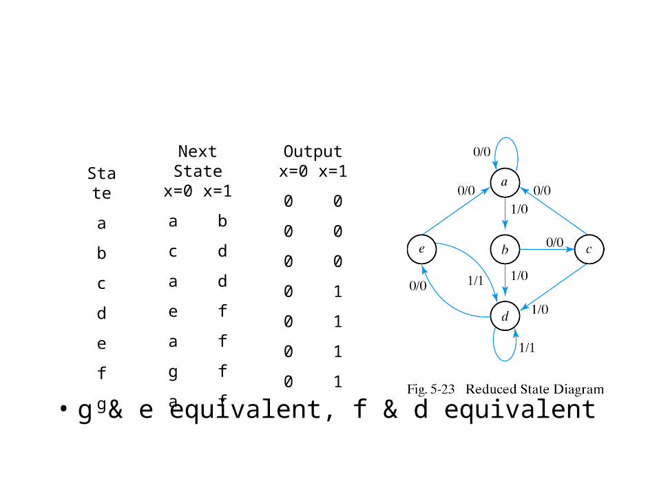
• g & e equivalent, f & d equivalent
State
a
b
c
d
e
f
g
Next Statex=0 x=1
a b
c d
a d
e f
a f
g f
a f
Outputx=0 x=1
0 0
0 0
0 0
0 1
0 1
0 1
0 1

State Assignment
Stateabcde
Binary000001010011100
Gray Code000001011010110
One-Hot0000100010001000100010000

Reduced State Table:Binary State Assignment
State
001
010
011
100
101
Next Statex=0 x=1
000 001
010 011
000 011
100 011
000 011
Outputx=0 x=1
0 0
0 0
0 0
0 1
0 1
Table 5-10

Design Procedure
• Develop State Diagram From Specs
• Reduce States
• Assign Binary values to States
• Write Binary-coded State Table
• Choose Flip-Flops
• Derive Input and Output Equations
• Draw the Logic Diagram
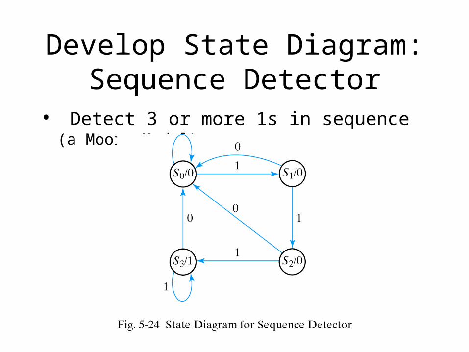
Develop State Diagram:Sequence Detector
• Detect 3 or more 1s in sequence (a Moore Model)

D Flip-Flop Input Equations
A(t+1) = DA(A,B,x) = (3,5,7) B(t+1) = DB(A,B,x) = (1,5,7)
y(A,B,x) = (6,7)
StateA B
0 00 00 10 11 01 01 11 1
Next StateA B
0 00 10 01 00 01 10 01 1
Output y
0 0 0 00011
Input x
0 1 0 10101
Input equations come directly from the next state in D Flip-Flop design

Simplified Boolean Equations
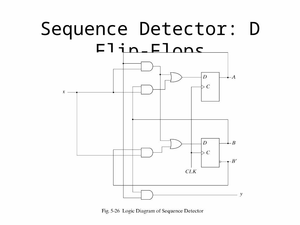
Sequence Detector: D Flip-Flops
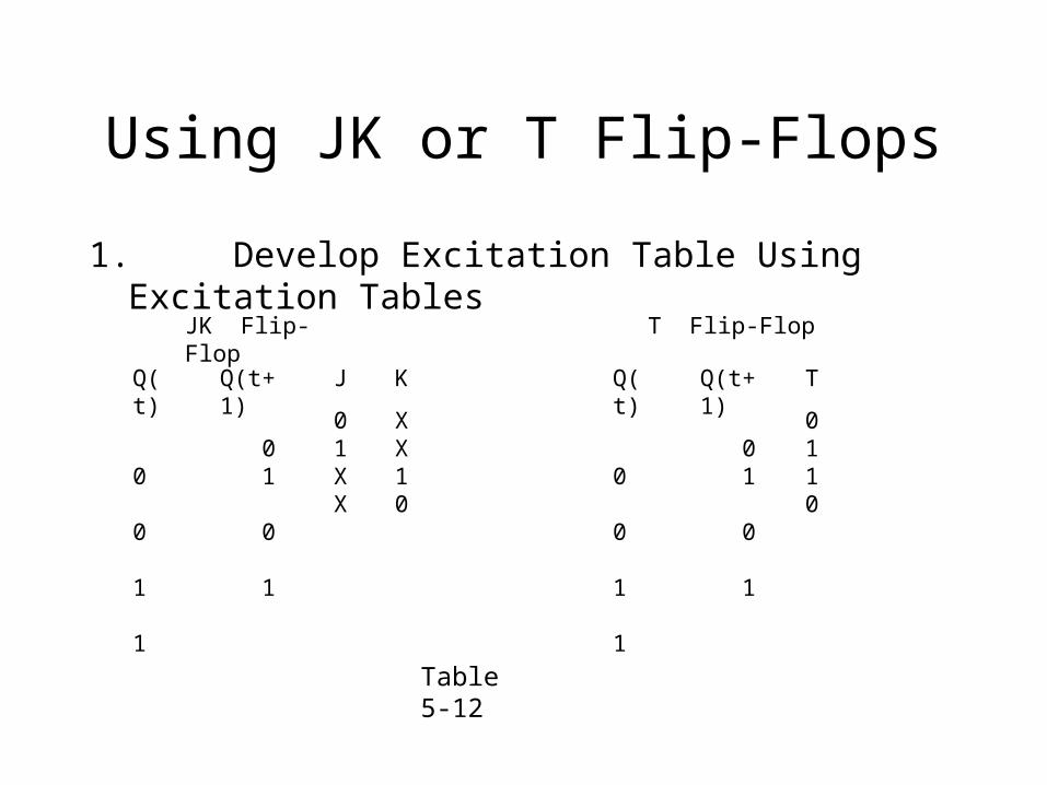
Using JK or T Flip-Flops
1. Develop Excitation Table Using Excitation Tables
Table 5-12
K
XX10
J
01XX
Q(t+1)
0 1 0 1
JK Flip-Flop
Q(t)
0 0 1 1
T
0110
T Flip-Flop
Q(t+1)
0 1 0 1
Q(t)
0 0 1 1
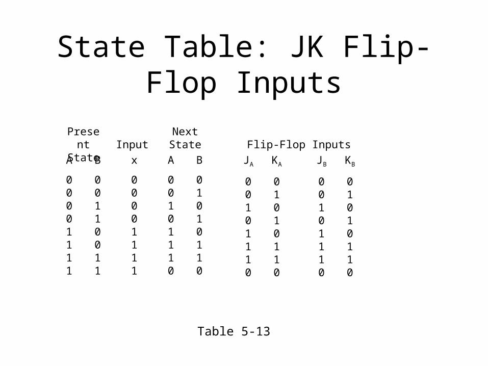
State Table: JK Flip-Flop Inputs
B
00110011
A
00001111
PresentState
x
00001111
Input
B
01010110
A
00101110
NextState
KA
01010110
JA
00101110
KB
01010110
JB
00101110
Flip-Flop Inputs
Table 5-13

Maps for J and K Input Equations
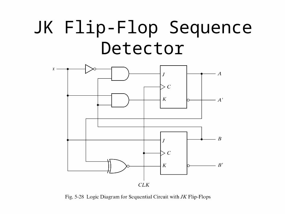
JK Flip-Flop Sequence Detector
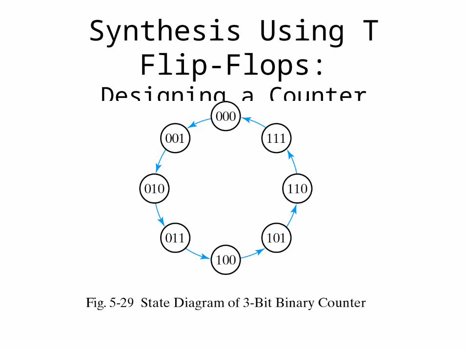
Synthesis Using T Flip-Flops:Designing a Counter

3-Bit Counter State Table
A1
00110011
A2
00001111
Present State
A0
01010101
A1
01100110
A2
00011110
TA1
01010111
TA2
00010001
TA0
11111111
Flip-Flop InputsNext State
A0
10101010
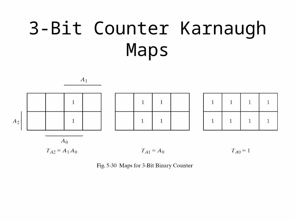
3-Bit Counter Karnaugh Maps

The 3-Bit Counter