digital axle counters - indian railways
TRANSCRIPT

GOVERNMENT OF INDIA
MINISTRY OF RAILWAYS
Handbook on Troubleshooting
of
DIGITAL AXLE COUNTERS
CAMTECH/S/PROJ/2013-14/HB- DAC (T) SEPTEMBER 2013
MAHARAJPUR, GWALIOR – 474 005

FOREWORD
Diagnostics and troubleshooting procedures of any equipment help the engineers and technicians in rectifying their failures quickly and in correct manner thereby minimizing the failure time. As Digital Axle Counters have been installed in station yards as well as in Block sections and Automatic Signalling sections of Indian Railways, there is always a need for the availability of troubleshooting guidelines for quick reference. CAMTECH has made an effort in this direction by preparing this handbook for Signal maintenance personnel.
I hope that this handbook will help the signal maintenance personal in efficiently rectifying the failures of Digital Axle Counters. Any suggestions for further improvement are welcome.
CAMTECH Gwalior A.R.Tupe Date: 30.09.2013 Executive Director

PREFACE
Digital Axle Counters are microcontroller and software based systems. These are manufactured by different firms and hence the troubleshooting procedures are accordingly different. This handbook has been prepared to help the signal personnel in effectively rectifying the faults in the Digital Axle Counters installed in their section. This handbook is the sequel to the handbook on “Maintenance of Digital Axle Counters” earlier prepared by CAMTECH, hence for better understanding of the subject, this handbook may be also be referred along with the troubleshooting.
It is clarified that this handbook does not supersede any existing provisions laid down in Signal Engineering Manual, Railway Board publications and RDSO publications. This handbook is not statutory and instructions given in it are for the purpose of guidance only.
We are sincerely thankful to Shri S. Bandopahyay, Sr.D.S.T.E./ Bhopal/WCR, Shri M.Uppal, Sr D.S.T.E./Kota/WCR, M/s Eldyne Electro-systems, M/s Siemens, M/s Central Electronics Ltd, M/s G.G.Tronics and field personnel who helped us in preparation of the handbook.
Since technological upgradation and learning is a continuous process, you may feel the need for some addition/modification in this handbook. If so, please feel free to give your comments on email address [email protected] or write to us at Indian Railways Centre for Advanced Maintenance Technology, In front of Adityaz Hotel, Airport Road, Maharajpur, Gwalior (M.P.) 474005.
CAMTECH Gwalior D.K.M.Yadav Date: 30.09.2013 Jt .Director (S&T)

Contents
of
Handbook on Troubleshooting of Digital Axle Counters
Section Description Pages
Foreword IV
Preface VI
Contents VIII
Correction Slip X
Disclaimer XII
About Troubleshooting of Digital Axle Counters 1
I Troubleshooting – Eldyne AzLS Digital Axle Counter 1-9
II Troubleshooting – Eldyne AzLM Digital Axle Counter 1-24
III Troubleshooting- Siemens Az S 350 U Multi Section Digital Axle Counter
1-16
IV Troubleshooting - DACF 710 A & DACF 710 P CEL SSADC 1-27
V Troubleshooting of SSDAC-G36 G.G.Tronics Single Section Digital Axle Counter
1-5

ISSUE OF CORRECTION SLIPS
The correction slips to be issued in future for this handbook will be numbered as follows:
CAMTECH/S/PROJ/2013-14/HB-DAC(T)/2.0# XX date .......
Where “XX” is the serial number of the concerned correction slip (starting from 01 onwards).
CORRECTION SLIPS ISSUED
Sr. No. of Correction
Slip
Date of issue
Page no. and Item No. modified
Remarks

DISCLAIMER
It is clarified that the information given in this handbook does not supersede any
existing provisions laid down in the Signal Engineering Manual, Railway Board and
RDSO publications. This document is not statuary and instructions given are for
the purpose of guidance only. If at any point contradiction is observed, then SEM,
Railway Board/RDSO guidelines may be referred or prevalent Zonal Railways
instructions may be followed.
----------------------------------------------------------------------------------------------------
OUR OBJECTIVE
To upgrade Maintenance Technologies and Methodologies and achieve improvement in Productivity and Performance of all Railway assets and manpower which inter-alia would cover Reliability, Availability and Utilisation.
If you have any suggestion & any specific comments, please write to us:
Contact person: Director (Signal & Telecommunication)
Postal Address: Centre for Advanced Maintenance Technology, Maharajpur,
Gwalior (M.P.) Pin Code – 474 005
Phone : 0751 - 2470185
Fax : 0751 – 2470841
Email : [email protected]

Section I
Troubleshooting of
Eldyne AzLS Single Section Digital Axle Counter
CAMTECH/S/PROJ/2013-14/HB- DAC (T) September 2013

Contents Section I - Troubleshooting – Eldyne AzLS Digital Axle Counter
Clause No. Description Page No.
1.1 Introduction 1
1.2 LED indications on Analog card 1
1.3 Sequence of LED indications on Analog card with wheel movement over Sk1 & Sk2
1
1.4 LED indications on Digital Card 3
1.5 LED diagnostics after restart 4
1.6 Diagnostics through LED indications on Digital Card 5
1.7 Troubleshooting chart for analog card of AzLS 7
1.8 Troubleshooting chart for digital card of AzLS 9

CAMTECH/S/PROJ/13-14/HB-DAC (T)
Section I: Troubleshooting Eldyne AzLS September 2013
1
Section I Troubleshooting
Az LS Eldyne Single Section Digital Axle Counter 1.1 Introduction Troubleshooting in AzLS can be done with the help of LEDs provided on the Analog and Evaluator/Digital cards of the Trackside Electronic Unit (EAK) which indicate the status of the system. Diagnostics LED indications conforming to AzLS version V1.1 are given in the following paragraphs. 1.2 LED indications on Analog card
Fig. 1.1 : LED indications on Analog card (As viewed from top)
LED Colour Indication H1 - 1 Red On: Wheel on rail contact 1(Sk1); Off: No wheel on rail contact 1(Sk1) H1 - 2 Green Off: Wheel approaching; Flashing: Sensor voltage (MESSAB1) within
tolerance no wheel approaching. H2 - 1 Red On: Wheel on rail contact 2 (Sk2); Off: No wheel on rail contact 2 (Sk2) H2 - 2 Green Off: Wheel approaching; Flashing: Sensor voltage (MESSAB2) within
tolerance no wheel approaching. H3 - 1 Red On: Voltage H24V out of tolerance; Off: Voltage H24V within tolerance. H3 - 2 Green On: Voltage H5V O.K.; Off: Voltage H5V not O.K.
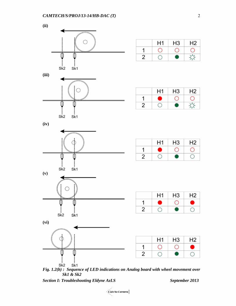
1.3 Sequence of LED indications on Analog card with wheel movement over
Sk1 & Sk2 (i)
→ LED ON (Steady)
☼ ☼ → LED ON (Blinking)
Ο Ο → LED OFF (Blank) Fig. 1.2(a) : Sequence of LED indications on Analog board with wheel movement over
Sk1 & Sk2
CAMTECH/S/PROJ/13-14/HB-DAC (T)
Section I: Troubleshooting Eldyne AzLS September 2013
2
(ii)
(iii)
(iv)
(v)
(vi)
Fig. 1.2(b) : Sequence of LED indications on Analog board with wheel movement over
Sk1 & Sk2

CAMTECH/S/PROJ/13-14/HB-DAC (T)
Section I: Troubleshooting Eldyne AzLS September 2013
3
(vii)
(viii)
(ix)
Fig. 1.2(c) : Sequence of LED indications on Analog board with wheel movement over
Sk1 & Sk2
1.4 LED indications on Digital card
Fig.1.3: LED indications on Digital Card (As viewed from top)

CAMTECH/S/PROJ/13-14/HB-DAC (T)
Section I: Troubleshooting Eldyne AzLS September 2013
4
^ Disturbance indicates an error in the system due to any problem in communication medium and/or power. System is re-settable after rectifying the problem and without putting the power off.
* Defect indicates an error in the system due to any problem in analog card and/or digital card and/or motherboard. Power to be made OFF and then ON for resetting the system after rectifying the problem.
1.5 LED diagnostics after restart
LED Colour ON State OFF State Blinking State
H1/1 & H5/1 Green N.A. No function N.A. H1/2 & H5/2 Green N.A. No function N.A. H2/1 & H6/1 Green CPU test started CPU test completed successfully
(after approx. 10 sec.) N.A.
H2/2 & H6/2 Green RAM test started
RAM test completed successfully (after approx. 1 sec.)
N.A.
H3/1 & H7/1 Red ROM test started
ROM test completed successfully (after approx. 30 sec.)
N.A.
H3/2 & H7/2 Green ROM test started
ROM test completed successfully (after approx. 30 sec.)
N.A.
H4/1 & H8/1 Red ROM test started
ROM test completed successfully (after approx. 30 sec.)
N.A.
H4/2 & H8/2 Red ROM test started
ROM test completed successfully (after approx. 30 sec.)
N.A.
LED Colour Indication if permanently ON
Indication if permanently OFF
Flashing
H1/H5 - 1 Green Preparatory reset is input Preparatory reset is not input
H1/H5 – 2 Green Voltage on relay coil (Section Clear)
No voltage on relay coil (Section Occupied/Disturbed/Defect)
H2/H6 – 1 Green Telegrams from all other detection point received
Telegram missing/Communication loss
H2/H6 – 2 Green No transmission of telegram
Transmission of telegram is taking place.
H3/H7 – 1 Red Negative axles in section After accepting reset After restart and after test phase.
H3/H7 – 2 Green Single point reset: Reset command accepted . Co-operative reset: Reset command accepted at one detection point.
No reset active or rejected.
Sweeping in progress (only for preparatory reset)
H4/H8 – 1 Red Disturbance^ of own detection point computer.
No disturbance Disturbance of other detection point received.
H4/H8 – 2 Red Defect* of own detection point computer
No defect Defect of other detection point received.

CAMTECH/S/PROJ/13-14/HB-DAC (T)
Section I: Troubleshooting Eldyne AzLS September 2013
5
1.6 Diagnostics through LED indications on Digital Board Status of a track section can be ascertained through pattern of lit LEDs during various
stages.
→ LED ON (Steady), ☼ ☼ → LED ON (Blinking), Ο Ο → LED OFF (Blank) Fig.1.4 (i) Pattern of lit LEDs on Digital Card during various stages of track section

CAMTECH/S/PROJ/13-14/HB-DAC (T)
Section I: Troubleshooting Eldyne AzLS September 2013
6
→ LED ON (Steady)
☼ ☼ → LED ON (Blinking)
Ο Ο → LED OFF (Blank) Fig.1.4 (ii) Pattern of lit LEDs on Digital Card during various stages of track section

CAMTECH/S/PROJ/13-14/HB-DAC (T)
Section I: Troubleshooting Eldyne AzLS September 2013
7
1.7 Troubleshooting charts for Analog Card of AzLS
Fig.1.5 (i): Troubleshooting chart for Analog Card of AzLS

CAMTECH/S/PROJ/13-14/HB-DAC (T)
Section I: Troubleshooting Eldyne AzLS September 2013
8
Fig.1.5 (ii): Troubleshooting chart for Analog Card of AzLS

CAMTECH/S/PROJ/13-14/HB-DAC (T)
Section I: Troubleshooting Eldyne AzLS September 2013
9
1.8 Troubleshooting chart for Digital Card AzLS
Fig.1.6 : Troubleshooting chart for Digital Card of AzLS If the AzLS system experiences frequent loss of telegram (due to fault in communication media or power supply), the system performs a safe act by halting the CPUs on the Digital Card. If the Digital card halts, the EAK is to be powered OFF and then ON to make it functional. To prevent the occurrence of Digital Card halt phenomena, the possibility of electromagnetic induction in the communication media is to be reduced. Following preventive measures are to be taken to arrest EMC/EMI problem and ensure trouble-free operation of the system:

CAMTECH/S/PROJ/13-14/HB-DAC (T)
Section I: Troubleshooting Eldyne AzLS September 2013
10
The cross pair conductors in quad cable (used for axle counter communication)
when exposed from the protective jacket of the quad cable, must be twisted to the
points of termination of the conductors.
Unused quad pairs inside location box must be earthed.
All cable segments to be earthed at one end only.
The ripple content of the power supply must be less than 20 mV AC.
A free wheeling diode (IN4007) must be connected across the coil of each Vital
and Reset relay.
LED indication Digital Card in halt state: Case 1 Case 2 Case 3
H2-1 (GREEN)-ON
H2-2 (GREEN)-ON
H2-2 (GREEN) - ON
H3-2 (GREEN) - ON
H4-2 (RED) -ON
H-1 (RED)-ON
H3-2 (GREEN)-ON
H3-1 (RED)- ON
H3-2 (GREEN)- ON
H6-2 (GREEN) - ON
H7-2 (GREEN) - ON
H8-2 (RED) -ON
H4-1 (RED)- ON
H4-2 (RED)- ON
H4-1 (RED)- ON
H4-2 (GREEN)- ON
H7-1 (RED)- ON
H7-2 (GREEN)- ON
H6-1 (GREEN)-ON
H6-2 (GREEN)-ON
H8-1 (RED)-ON
H8-2 (RED)-ON
H7-1 (RED)- ON
H7-2 (GREEN)- ON
H8-1 (RED)- ON
H8-2 (RED)- ON

Section II
Troubleshooting of
Eldyne AzLM
Multi Section Digital Axle Counter
CAMTECH/S/PROJ/2013-14/HB- DAC (T) September 2013

Contents
Section II - Troubleshooting – Eldyne AzLM Digital Axle Counter
Clause No. Description Page No.
2.1 Introduction 1
2.2 Diagnostics through LED indications on EAK 1
2.3 Diagnostics through LED indications on Axle Counter Evaluator (ACE) 2
2.4 System Diagnosis by Computer 6
2.5 Graphical Diagnostic Interface (GDI) – AzLM 9
2.6 Do’s & Don’ts 17
2.7 Troubleshooting Flowchart for Analog Card of AzLM 18
2.8 Troubleshooting Flowchart for Digital Card of AzLM 20
2.9 Troubleshooting Flowchart for serial I/O Card of AzLM 22
2.10 Troubleshooting Flowchart for section disturb/defect 24

CAMTECH/S/PROJ/13-14/HB-DAC (T)
Section II - Trouble shooting– Eldyne AzLM September 2013
1
Section II Troubleshooting
Az LM
Eldyne Multi Section Digital Axle Counter
2.1 Introduction Troubleshooting in AzLM can be done with the help of LED indications provided on the Analog and Evaluator/Digital cards of the Trackside Electronic Unit (EAK) as well as on the front panel of boards in Axle Counter Evaluator (ACE). A Diagnostic Interface Software is also provided as an additional tool which interrogates the system to determine its status.
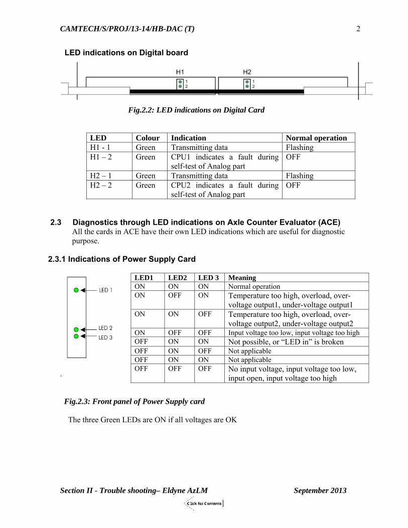
2.2 Diagnostics through LED indications on EAK LED indications on Analog board
Fig.2.1 :LED indications on Analog card (As viewed from top)
LED Colour Indication H1 - 1 Red On: Wheel on rail contact 1(Sk1); Off: No wheel on rail contact 1(Sk1) H1 - 2 Green Off: Wheel approaching; Flashing: Sensor voltage (MESSAB1) within
tolerance no wheel approaching. H2 - 1 Red On: Wheel on rail contact 2 (Sk2); Off: No wheel on rail contact 2 (Sk2) H2 - 2 Green Off: Wheel approaching; Flashing: Sensor voltage (MESSAB2) within
tolerance no wheel approaching. H3 - 1 Red On: Voltage H24V out of tolerance; Off: Voltage H24V within tolerance. H3 - 2 Green On: Voltage H5V O.K.; Off: Voltage H5V not O.K. Note: The Sequence of LED indications on Analog Board with wheel movement over Sk1 &
Sk2 is same as that of AzLS.
CAMTECH/S/PROJ/13-14/HB-DAC (T)
Section II - Trouble shooting– Eldyne AzLM September 2013
2
LED indications on Digital board
Fig.2.2: LED indications on Digital Card
LED Colour Indication Normal operation H1 - 1 Green Transmitting data Flashing H1 – 2 Green CPU1 indicates a fault during
self-test of Analog part OFF
H2 – 1 Green Transmitting data Flashing H2 – 2 Green CPU2 indicates a fault during
self-test of Analog part OFF
2.3 Diagnostics through LED indications on Axle Counter Evaluator (ACE) All the cards in ACE have their own LED indications which are useful for diagnostic
purpose.
2.3.1 Indications of Power Supply Card
. Fig.2.3: Front panel of Power Supply card
The three Green LEDs are ON if all voltages are OK
LED1 LED2 LED 3 Meaning ON ON ON Normal operation ON OFF ON Temperature too high, overload, over-
voltage output1, under-voltage output1 ON ON OFF Temperature too high, overload, over-
voltage output2, under-voltage output2 ON OFF OFF Input voltage too low, input voltage too high OFF ON ON Not possible, or “LED in” is broken OFF ON OFF Not applicable OFF ON ON Not applicable OFF OFF OFF No input voltage, input voltage too low,
input open, input voltage too high

CAMTECH/S/PROJ/13-14/HB-DAC (T)
Section II - Trouble shooting– Eldyne AzLM September 2013
3
2.3.2 Indications on CPU Card
Fig. 2.4.: Front panel of CPU card The alphanumeric display on the CPU Card shows the following indications: Start up: Initially the display is illuminated for a short while, then the screen goes blank for a short period. After that a ’_’ sign appers and stays for approximately 2.5 minutes. Then the normal operation begins. Normal operation: Rotating bar
Faults: Axle counter application stopped, diagnostic still available: Alternating x and X Axle counter application and diagnostic stopped: Standing bar in any orientation LED 1 The flashing LED shows the communication on the Ethernet interface LED 2 & 3 The flashing LEDs show the communication between the processors. In
normal operation both LEDs flash. LED 4 Not used
1. Ethernet interface 2. Reset Button 3. LED 1…4
LED1: The flashing LED shows the communication on the Ethernet interface. LED2 & 3: Flashing LEDs show the communication between the processors. In normal condition, both LEDs flash. LED4: Not used.
4. Alphanumeric display The display shows a rotating bar if the CPU is operational
5. Diagnostic interface The serial interface socket to which the serial interface of the diagnostic PC is connected.

CAMTECH/S/PROJ/13-14/HB-DAC (T)
Section II - Trouble shooting– Eldyne AzLM September 2013
4
2.3.3 Indications of Serial I/O Card The serial I/O interface consists of two independent ISDN transmission paths and one I/O
board is used for maximum two detection points.
Fig.2.5: Front panel of Serial I/O card
2.3.4 LED Diagnostics of Serial I/O Card
LEDON (Steady) ●LED ON (Flashing) LED OFF (Blank)
Fig.2.6: LED indications on Serial I/O card during different stages
LED ISDN-link channel 1 LED ISDN-link channel 2
• ON for link state “connected”(if the ISDN link to the associated detection point is operational)
• otherwise OFF LED ISDN-telegram channel 2 LED ISDN-telegram channel 1
• flashes while receiving an ISDN-telegram(if a valid ISDN telegram was received from the associated detection point)
• otherwise OFF
●●
The status of Detection Point is OK
Loss of communication between Detection Point and ACE
Detection Point computer not working; computer halted
Detection Point computer not working; computer halted

CAMTECH/S/PROJ/13-14/HB-DAC (T)
Section II - Trouble shooting– Eldyne AzLM September 2013
5
2.3.5 Parallel I/O Card: LED Diagnostics (AzLM)
Fig.2.7: LED diagnostics with Parallel I/O card
2.3.6 Indications of Parallel I/O Card
Fig.2.8: Front panel of Parallel card
LED row
Channel Colour Function (When ON)
1 1 & 2 Green Vital input 1 activated 2 1& 2 Green Vital input 2 activated 3 1 & 2 Green Section Clear, Relay
picked up (Voltage on Relay)
4
1 Yellow Non-vital output 1 activated
2 Yellow Non-vital output 2 activated
5 1 Yellow Non-vital output 3 activated
2 Yellow Non-vital output 4 activated
6 1 & 2 Green Polling
Key Switch Push button
Vital Input 1: Preparatory Reset without Acknowledgement Vital Input 2: Unconditional Reset Non-vital Output 1: Waiting for Operation (Train Movement) Non-vital Output 2: Technical Defect Non-vital Output 3: Not applicable Non-vital Output 4: Not applicable Fig.3.14: Details of Inputs and Outputs of Parallel I/O Card

CAMTECH/S/PROJ/13-14/HB-DAC (T)
Section II - Trouble shooting– Eldyne AzLM September 2013
6
2.4 System Diagnosis by Computer The diagnostic data are stored in the Computer Board as Historical data Element status The data is stored together with the associated internal system time of the ACE. The internal system time is converted to real time and displayed it together with the data. The historical data may be used to reconstruct the sequential occurrence of events. The element status indicates the momentary status of the following elements Sections Detection points Interfaces Computers Software Versions System diagnostics for AzLM can be done with the help of a PC loaded with diagnostic software. The diagnostic PC must be a Pentium PC having a serial interface RS-232 (19200 bps) port with Windows operating system. The serial interface has to be connected to the serial interface port on the CPU Card 1 of ACE by a Null-modem cable having female DB9 connector at both ends. After running the diagnostic software, the system data (viz. Elements current data and Historical data) can be downloaded and analyzed on the PC. The elements data includes status of section, detection point, interfaces, versions etc. The status of elements is displayed on the PC screen in a coded message format with date & time of occurrence. Note: The null-modem cable should always be kept connected at the CPU card end as well at the diagnostic PC end. In case the null-modem cable needs to get disconnected, it should be disconnected from both ends. Diagnostic Messages The following format of diagnostic messages is used in the history files and element data files generated by the diagnostic tool.
RNr Replica Date/Time Element
Type Element Number
Diagnostic Event
Parameter
Where RNr - CPU number from where the diagnostic messages are read out. Replica 0 - Message from all running CPUs 1 - Message from CPU1 (that is, CPU Card on left side of ACE subrack) 2 - Message from CPU2 (that is, CPU Card on right side of ACE subrack) 3 - Message from CPU1 and CPU2

CAMTECH/S/PROJ/13-14/HB-DAC (T)
Section II - Trouble shooting– Eldyne AzLM September 2013
7
Date/Time Date and time of occurrence of diagnostic event. Element Type There are several element types, e.g., section, detection point, parallel I/O card, serial I/O card etc. Element Number Each element has its own number (e.g., n = 1, 2, …) which is specified in the site specific data. These element numbers are listed in the element window of the diagnostic tool together with the names which are used in the layout plan. Diagnostic Event There are five types of diagnostic events, namely, operational name, site specific data, state, version and axles. Parameter Information about different events. Following is the example of display of a diagnostic message on the PC screen RNr Replica Date/Time Element
Type Element Number
Diagnostic Event
Parameter Explanation
1 3 yy:mm:dd hh:mm:ss:sss
Detection Point
n DP information
VERSATZ x (y) Counting fault of x axles in DP n. The new difference between the CPUs is y axles. Information: CPU 1 and 2 are sending a different number of counted axles. This may be caused by a miscount in one CPU due to non-standard small wheels
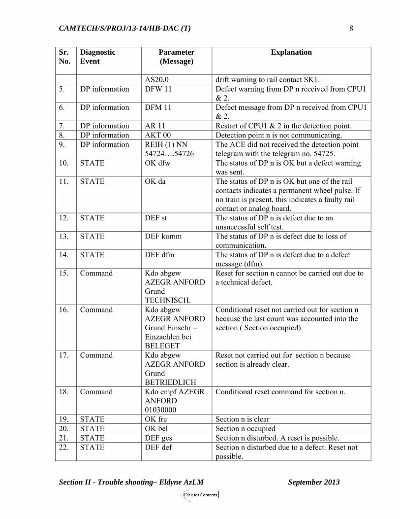
Some coded messages and there interpretations useful for diagnostic purposes are given below: Sr. No.
Diagnostic Event
Parameter (Message)
Explanation
1. DP information WLP ZPR 1+0+1 Wheel pulse longer than 3 seconds detected at DP n.
2. DP information VERSTAZI(1) Counting fault in DP n. 3. DP information STA 01 011 Self test of analog circuits failed in DP n
message received from SK1 4. DP information DRW AS11,1 Drift warning from DP n. CPU1 & 2 send a
CAMTECH/S/PROJ/13-14/HB-DAC (T)
Section II - Trouble shooting– Eldyne AzLM September 2013
8
Sr. No.
Diagnostic Event
Parameter (Message)
Explanation
AS20,0 drift warning to rail contact SK1. 5. DP information DFW 11 Defect warning from DP n received from CPU1
& 2. 6. DP information DFM 11 Defect message from DP n received from CPU1
& 2. 7. DP information AR 11 Restart of CPU1 & 2 in the detection point. 8. DP information AKT 00 Detection point n is not communicating. 9. DP information REIH (1) NN
54724….54726 The ACE did not received the detection point telegram with the telegram no. 54725.
10. STATE OK dfw The status of DP n is OK but a defect warning was sent.
11. STATE OK da The status of DP n is OK but one of the rail contacts indicates a permanent wheel pulse. If no train is present, this indicates a faulty rail contact or analog board.
12. STATE DEF st The status of DP n is defect due to an unsuccessful self test.
13. STATE DEF komm The status of DP n is defect due to loss of communication.
14. STATE DEF dfm The status of DP n is defect due to a defect message (dfm).
15. Command Kdo abgew AZEGR ANFORD Grund TECHNISCH.
Reset for section n cannot be carried out due to a technical defect.
16. Command Kdo abgew AZEGR ANFORD Grund Einschr = Einzaehlen bei BELEGET
Conditional reset not carried out for section n because the last count was accounted into the section ( Section occupied).
17. Command Kdo abgew AZEGR ANFORD Grund BETRIEDLICH
Reset not carried out for section n because section is already clear.
18. Command Kdo empf AZEGR ANFORD 01030000
Conditional reset command for section n.
19. STATE OK fre Section n is clear 20. STATE OK bel Section n occupied 21. STATE DEF ges Section n disturbed. A reset is possible. 22. STATE DEF def Section n disturbed due to a defect. Reset not
possible.

CAMTECH/S/PROJ/13-14/HB-DAC (T)
Section II - Trouble shooting– Eldyne AzLM September 2013
9
2.5 Graphical Diagnostic Interface (GDI) – AzLM GDI is a newly developed tool for diagnostics purposes in AzLM with a user friendly menu. Unlike in older version of Diagnostic software, the user need not refer to the list of coded messages (parameters) for failure diagnostics. The required information can be obtained simply by clicking on the menu available on the screen.
Troubleshooting using GDI For troubleshooting with the help of GDI, following steps are to be performed:
Connect the diagnostic PC with the diagnostic interface of ACE. Start the diagnostic PC Start the diagnostic program via icon Identify disturbed sections Identify disturbed detection points
GDI Menu
Fig.2.9: Screen showing GDI Menu Following is the description of the GDI Menu items: New - Creates new ACE data Open - Opens existing ACE data Close - Closes ACE data Exit - Exits Graphical Diagnostic Interface program Open Diagnostic Printout - Opens saved Diagnostic files (*.diag). Terminal - Opens a console window used by development engineers for text-base input and
output Refresh - If checked, the display on the GDI screen gets refreshed cyclically.

CAMTECH/S/PROJ/13-14/HB-DAC (T)
Section II - Trouble shooting– Eldyne AzLM September 2013
10
GDI - To Create a new ACE Data If the Diagnostic PC is connected to the ACE for the first time, ACE to be created by selecting ‘ACE’ ‘New’. Choose the type of ACE and interface.
Fig.2.10:Selecting the type of ACE and Interface Save ACE data in the Diagnostic PC. The name of the data file should be as same as the name of project site so that the data file can be easily identified later.
Fig.2.11: Assigning File Name and saving data in Diagnostic PC

CAMTECH/S/PROJ/13-14/HB-DAC (T)
Section II - Trouble shooting– Eldyne AzLM September 2013
11
GDI - To Open an ACE Select ‘ACE’ ‘Open’ to get the Open window Choose the required data file and open it.
Fig.2.12: Selecting the required data file for opening When an ACE is opened for the first time, it takes some time to get opened. Later the same ACE can be opened much faster.
Fig.2.13: Display on screen after opening ACE data file

CAMTECH/S/PROJ/13-14/HB-DAC (T)
Section II - Trouble shooting– Eldyne AzLM September 2013
12
Graphical Diagnostic Interface (GDI)
Fig.2.14: Front end screen of GDI
Graphical Diagnostic Interface (GDI) – Serial I/O
Fig.2.15: Display of Preprocessor1 state of Serial I/O Card

CAMTECH/S/PROJ/13-14/HB-DAC (T)
Section II - Trouble shooting– Eldyne AzLM September 2013
13
Fig.2.16: Display of Preprocessor 1 history of Serial I/O Card
Graphical Diagnostic Interface (GDI) – Parallel I/O
Fig.2.17: Display of state of Parallel I/O 1 Card

CAMTECH/S/PROJ/13-14/HB-DAC (T)
Section II - Trouble shooting– Eldyne AzLM September 2013
14
Fig.2.18: Display of Parallel I/O 1 Card history
Fig.2.19: Display of site specific data of Parallel I/O 1 Card

CAMTECH/S/PROJ/13-14/HB-DAC (T)
Section II - Trouble shooting– Eldyne AzLM September 2013
15
Graphical Diagnostic Interface (GDI) – CPU
Fig.2.20: Display of state of ACE in chronological order
Fig.2.21: Display of history of ACE

CAMTECH/S/PROJ/13-14/HB-DAC (T)
Section II - Trouble shooting– Eldyne AzLM September 2013
16
Fig.2.22: Display of site specific data of ACE
Fig 2.23.: Display of messages of operating system

CAMTECH/S/PROJ/13-14/HB-DAC (T)
Section II - Trouble shooting– Eldyne AzLM September 2013
17
Fig.2.24: Display of versions of DPs and preprocessors
2.6 Do’s & Don’ts Connect serial interface of diagnostic PC to the left-side CPU. Connect Ethernet interface of diagnostic PC to the right-side CPU.
Fig.2.25: Diagnostic interfaces of ACE Never connect the diagnostic PC to the serial interface as well as Ethernet interface in the ACE at same time. Never connect the diagnostic PC to more than one ACE at same time.
Left side CPU – connector for serial interface of diagnostic PC
Right side CPU – connector for Ethernet interface of diagnostic PC

CAMTECH/S/PROJ/13-14/HB-DAC (T)
Section II - Trouble shooting– Eldyne AzLM September 2013
18
2.7 Troubleshooting Flowchart for Analog Card of AzLM
Fig.2.26 (i): Troubleshooting Flowchart for Analog Card of AzLM

CAMTECH/S/PROJ/13-14/HB-DAC (T)
Section II - Trouble shooting– Eldyne AzLM September 2013
19
Fig.2.26 (ii): Troubleshooting Flowchart for Analog Card of AzLM

CAMTECH/S/PROJ/13-14/HB-DAC (T)
Section II - Trouble shooting– Eldyne AzLM September 2013
20
2.8 Troubleshooting Flowchart for Digital Card of AzLM
Fig.2.27: Troubleshooting Flowchart for Digital Card of AzLM

CAMTECH/S/PROJ/13-14/HB-DAC (T)
Section II - Trouble shooting– Eldyne AzLM September 2013
21
If the AzLM system experiences frequent loss of telegram (due to fault in communication media or power supply), the system performs a safe act by halting the CPUs on the Digital Card. If the Digital card halts, the EAK is to be powered OFF and then ON to make it functional. To prevent the occurrence of Digital Card halt phenomena, the possibility of electromagnetic induction in the communication media is to be reduced. Following preventive measures are to be taken to arrest EMC/EMI problem and ensure trouble-free operation of the system:
The cross pair conductors in quad cable (used for axle counter communication) when exposed from the protective jacket of the quad cable, must be twisted to the points of termination of the conductors.
Unused quad pairs inside location box must be earthed.
All cable segments to be earthed at one end only.
The ripple content of the power supply must be less than 20 mV AC.
A free wheeling diode (IN4007) must be connected across the coil of each Vital and Reset relay.
LED indication Digital Card in halt state:
H1-1 (GREEN)-ON H1-2 (GREEN)-ON
H2-1 (GREEN)- ON H2-2 (GREEN)- ON
CAMTECH/S/PROJ/13-14/HB-DAC (T)
Section II - Trouble shooting– Eldyne AzLM September 2013
22
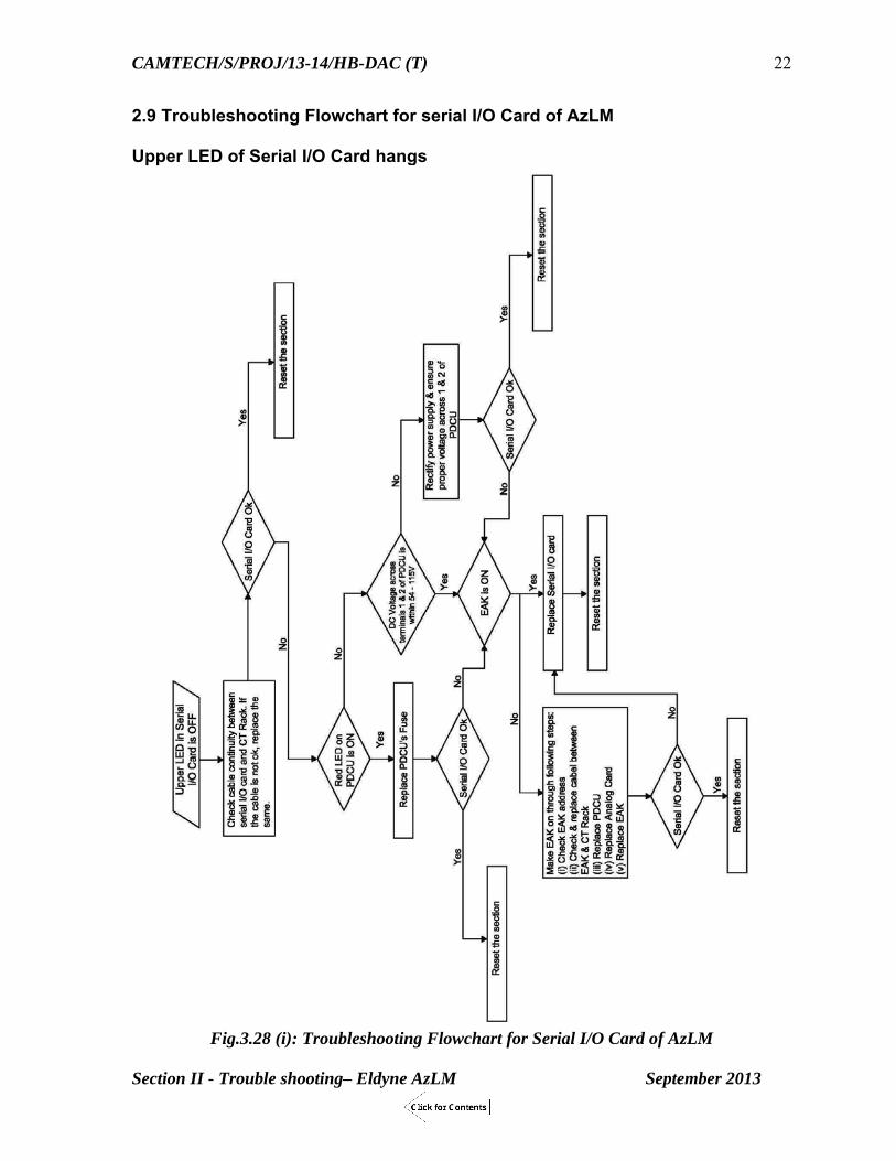
2.9 Troubleshooting Flowchart for serial I/O Card of AzLM Upper LED of Serial I/O Card hangs
Fig.3.28 (i): Troubleshooting Flowchart for Serial I/O Card of AzLM

CAMTECH/S/PROJ/13-14/HB-DAC (T)
Section II - Trouble shooting– Eldyne AzLM September 2013
23
Lower LED of Serial I/O Card is not blinking
Fig.2.28 (ii): Troubleshooting Flowchart for Serial I/O Card of AzLM

CAMTECH/S/PROJ/13-14/HB-DAC (T)
Section II - Trouble shooting– Eldyne AzLM September 2013
24
2.10 Troubleshooting Flowchart for section disturb/defect in AzLM
Fig. 2.29 : Troubleshooting Flowchart for Section disturb/defect in AzLM

Section III
Troubleshooting of
Siemens Az S 350 U
Multi Section Digital Axle Counter
CAMTECH/S/PROJ/2013-14/HB- DAC(T)
September 2013

Contents
Section III - Troubleshooting- Siemens Az S 350 U Multi Section Digital Axle Counter
Clause No. Description Page No.
3.1 Introduction 1
3.2 Outdoor equipment 1
3.3 Indoor Equipment 3
3.4 Fault finding and troubleshooting (Outdoor equipment) 4
3.5 Fault finding and troubleshooting (Indoor equipment) 5
3.6 Fault finding and troubleshooting - Indoor equipment 10
3.7 Rectifying failure of Evaluation Computer boards 10
3.8 Rectifying failure of Evaluation Computer boards after Emergency Shutdown
13
3.9 AzGrT Button Operation Error 14
3.10 Switching the Evaluation Computer On and Off 14
3.11 Replacing Boards 15
3.12 Restarting an Evaluation Computer 16
3.13 Special Board Replacement Conditions 16

CAMTECH/S/PROJ/13-14/HB-DAC (T)
Section III Troubleshooting Siemens Az S 350 U September 2013
1
Section III Troubleshooting
Az S 350 U
SIEMENS MULTI SECTION DIGITAL AXLE COUNTER
3.1 Introduction Az S 350 U consists of two main components:
Outdoor equipment Indoor equipment
The outdoor equipment is the ZP 43 wheel detection equipment (counting head) comprising a double wheel detector and a trackside connection box. Counting heads are installed at the limits of a track vacancy detection section. The indoor equipment consists of the evaluation computer. The counting head is connected to the Az S 350 U via a two-core cable Power Supply Following power supplies are required for functioning of the Axle Counter equipment:
5 V DC for internal operation 70 V DC for external operation of max. five counting heads
3.2 Outdoor equipment ZP 43 Wheel Detection Equipment
Fig.3.1: ZP43 Wheel Detection Equipment at site

CAMTECH/S/PROJ/13-14/HB-DAC (T)
Section III Troubleshooting Siemens Az S 350 U September 2013
2
3.2.1 Tools and Test Equipment required for adjustment Open-end, ring or box spanner, width across flats 13 Screwdriver 0.6 x 2.8 as per DIN 7437 Screwdriver 0.6 x 3.5 as per DIN 7437 Test equipment is Probe adapter board and multi-meter (Fluke-189 or equivalent) with measuring ranges. The probe adapter board SCN S25552-B43-D1 can be used during commissioning and maintenance for testing and adjusting work on the ZP 43 V Wheel Detection Equipment. Adjusting work (voltage and frequency measurements) can be performed using a commercially available multi-meter. Measuring sockets arranged in pairs are provided on the front. The multi-meter is connected to them.
Fig. 3.2: (i) ZP 43 V Wheel Detection Equipment with Probe Adapter Board (ii) Front panel of the Probe Adapter Board
Electrical parameters of ZP 43 V Wheel Detection Equipment Parameter Description Standard value Tolerance range
U60 WDE voltage 60 V DC 30 V to 72 V U24 Operating voltage 24 V DC 21.3 V to 22.4 V FS Transmitter frequency of
the double wheel detector43 kHz 42.8 kHz to 43.2
kHz F 1 Signal frequency 1 3.50 kHz 3.47 kHz to 3.53
kHz F 2
Signal frequency 2
6.37 kHz 6.31 kHz to 6.43 kHz
Ur1 Standard voltage 1 3.55 V DC 3.45 V to 3.65 V Ur2 Standard voltage 2 3.35 V DC 3.25 V to 3.45 V uE 1 Receiver voltage 1 AC 60 mV to 150 mV uE 2 Receiver voltage 2 AC 60 mV to 150 mV

CAMTECH/S/PROJ/13-14/HB-DAC (T)
Section III Troubleshooting Siemens Az S 350 U September 2013
3
3.3 Indoor Equipment Evaluation Computer The Evaluation Computer consists of plug-in circuit boards which are accommodated in a single-tier mounting frame with wiring backplane. Dummy boards are inserted in free slots for optional boards.
Fig. 3.3 : Front view of Az S 350 U Evaluation computer (including slot numbers)
3.3.1 Adjustments and measurements at Evaluation Computer On the front panel of each VESBA board, there are measuring sockets for fault diagnostics as well as LEDs for displaying the state of passage and a potentiometer for adapting to different cable lengths and setting the transmission level.
Sr. No.
Parameter Acceptable Range Observed Values CH1 CH2 CH3 CH4 CH5 CH6
1 Signal F1 2.9 to 3.1 V DC 2 Signal F2 2.9 to 3.1 V DC
Fig.3.4: VESBA board front panel view

CAMTECH/S/PROJ/13-14/HB-DAC (T)
Section III Troubleshooting Siemens Az S 350 U September 2013
4
3.4 Fault finding and troubleshooting (Outdoor equipment) ZP43 Wheel detection equipment WDE Supply Voltage U60 Fault : The WDE Supply voltage is below 30V DC.
Cause of fault Measure Break in signalling cable Check signalling cable WDE connected with reverse polarity Check polarity Short circuit or interruption in the lightening protection or jumper board
Replace lightning protection or jumper board
Voltage controller defective Replace band pass filter board . Generator board defective Replace generator board. No supply voltage from the indoor equipment
Locate Fault in the indoor equipment: Defective fuse: Check the signalling cable and interface boards in the evaluation unit for short circuit of the WDE supply voltage.
WDE Supply Voltage U24 Fault : The internal WDE voltage is lower than 21.3 V DC or higher than 22.4 V DC.
Cause of fault Measure Voltage controller defective Replace band pass filter board Fuse on the band pass filter board defective
Replace fuse.
Transmitter frequency fs
Fault: Transmitter frequency is out of the tolerance range. Frequency adjustment is not possible. Cause of fault Measure Generator defective Replace generator board Lightning protection elements defective Replace lightning protection board Frequency tuning board defective Replace mounting frame Double wheel detector (transmitter) defective
Replace double wheel detector (transmitter)
Signal frequencies f1 and f2 Fault: Signal frequency f1 and f2 is out of the tolerance range. Cause of fault Measure Double wheel detector loose Firmly tighten the fastening bolts.
Readjust transmitter frequency fs and signal frequencies f1 and f2.
Double wheel detector is installed incorrectly
Install double wheel detector correctly.

CAMTECH/S/PROJ/13-14/HB-DAC (T)
Section III Troubleshooting Siemens Az S 350 U September 2013
5
Receiver voltage UE1 and UE2 Fault: Receiver voltages are less than 60 mV. Cause of fault Measure Double wheel detector is defective or loose
Firmly tighten the fastening bolts or replace double wheel detector
The Double wheel detector is installed on a very high rail section
Check the double wheel detector for correct installation (drilling dimensions, secure fit of the screws, no stray metal parts in the vicinity). If UE1 and UE2 are at the least 54 mV and it is possible to adjust the signal frequencies to the set point no further measures are required.
3.5 Diagnostics through LED indications
SVK2150 (Power Supply) board The SVK2150 power supply board provides 5 V for the evaluation computer and 70 V or the counting heads. The SVK2150 board transforms the interlocking voltage into controlled voltages (5 V DC for computers, 12 V DC (used for predecessor systems only) and 70 V DC for counting heads). All voltages are monitored by voltage controllers. Input and output voltages are electrically isolated.
Fig.3.5: Front view of SVK2150 board The SVK2150 board is ready for operation when voltage is applied to the switching input. This is indicated by the yellow LED "Vin". When the switch on the front panel is set to "I", the yellow LEDs "5 V" and "70 V" ("12 V" is not used) indicate the presence of the voltages. In case of under-voltage, the output voltage is switched off. When the output voltage is missing, the control-circuit fuse (fuse 0.2 A; fast) on the front panel blows. The unit cannot go back into operation until this fuse has been replaced. If there is no voltage at all, the input fuse on the printed circuit board (fuse 8 A; slow-acting) has to be checked.

CAMTECH/S/PROJ/13-14/HB-DAC (T)
Section III Troubleshooting Siemens Az S 350 U September 2013
6
VAU board
The VAU processing and monitoring board, a CPU board, constitutes the failsafe microcomputer system (SIMIS C computer core). It provides monitoring and comparator functions for synchronous dual-channel microcomputer operation. Fig.3.6 : Indications of VAU board
STEU board - Normal display Display of operating states of the four track vacancy detection sections (TVDS) (during operation; operating state display). The display is shown in fig. below and the details are given on pages
Indication Description VGL(Yellow LED) Comparator SPW (Red LED) Voltage Controller PAB (Red LED) Program-controlled shutdown ANL (Red LED) Start-up Red button System reset
Fig. 3.7: Front view of STEU board; display of operating states for TVDS 1 to 4 Note The meaning of LED 4 (reset restriction) is only applicable to the AzGrT mode. In the vAzGrT mode LED 4 is permanently off.

CAMTECH/S/PROJ/13-14/HB-DAC (T)
Section III Troubleshooting Siemens Az S 350 U September 2013
7
3.5.1 Meaning of LEDS on STEU board –Normal display LED display *-Steady o-Flashing
Meaning/Fault Cause Effect Remedy
LED 0-* System reset Hardware reset Reset buttons on VAU boards have been pressed.
Power supply switched on
EC in permanently occupied state.
Obtain track clear indication via visual inspection.
Press AzGrT button after reset
LED 0-o Program controlled emergency shut down
EC fault resulting in asynchronous operation of the two channels.
AzGrT button has been pressed on one or both channels during hardware reset.
Asynchronism of block information.
For further possible causes refer operating manual.
Program controlled shutdown of EC results in permanently occupied state.
Program is caught in an endless loop.
On both VAU boards the LEDs VGL are switched off and the LEDS PAB are switched on.
Remove cause of fault.
Carry out hardware reset.
Obtain track clear indication via visual inspection.
Reset EC by pressing the AzGrT button.
LED 1-* Minus axle blocking effective
At least one axle more counted out than has been counted in.
Permanently occupied state caused by minus axle blocking.
Obtain track clear indication via visual inspection.
Reset EC by pressing AzGrT button.
Counting capacity exceeded (max. 32.767 axles)
Incorrect programming or counting direction of a counting head.
Counting head counting out is faulty.
Counting head maladjusted.
Permanently occupied state
Remove cause of fault.
Obtain track clear indication via visual inspection
Reset EC by pressing AzGrT button.

CAMTECH/S/PROJ/13-14/HB-DAC (T)
Section III Troubleshooting Siemens Az S 350 U September 2013
8
LED display *-Steady o-Flashing
Meaning/Fault Cause Effect Remedy
Undefined counted pulse
Inexplicable pulse detection by counting head
Permanently occupied state
Obtain track clear indication via visual inspection reset EC by pressing AzGrT button.
LED 2-* Count monitoring double wheel detector traversed on one channel only (e.g. shunting movement)
-- Permanently occupied state without counting.
Occupied state and display are maintained until next complete traversal of double wheel detector or next AzGrT operation.
--
Count monitoring counting head fault due to spurious pulse
Double wheel detector, after complete traversal, detected pulses on one channel only (more than 4ms.)
Double wheel detector during a traversal detected pulse due to spurious pulses (more than 4ms)
Double wheel detector without a traversal detected pulses due to spurious pulse (more than 4ms)
Counting error leading to a permanently occupied state
No counting error, at least one axle follows after the cause the track clear indication will be given after the train has passed display is switched off.
Occupied state without a train, occupied state and display are maintained until next traversal with track clear indication or until next AzGrT operation.
Check counting head concerned including cable.
Obtain track clear indication via visual inspection
Reset EC by pressing AzGrT button.
LED 3 -* Telegram transmis-sion faulty or switched off
Data transmission between Ecs is fully faulty.
Second EC has been switched off.
As long as the connection is interrupted or faulty data is received the TVDS with remote
Check connection between Ecs
Check whether second EC has

CAMTECH/S/PROJ/13-14/HB-DAC (T)
Section III Troubleshooting Siemens Az S 350 U September 2013
9
LED display *-Steady o-Flashing
Meaning/Fault Cause Effect Remedy
Second EC is in emergency shutdown state.
Data transmission between Ecs was faulty (DIP switch TELFM is set to off and double wheel detector detected no pulses).
counting heads remain in the occupied state.
Occupied state and display are maintained until next complete traversal of double wheel detector or next AzGrT operation (DIP switch TELFM set to off).
been switched off or is in an emergency shut down state (restart).
Reset EC by pressing AzGrT button.
Wait for train run. If TVDS remain occupied perform the measures above.
ED 4-* Reset restriction (RR)
One counting head of the TVDS detected pulses.
There are axles in the TVDS.
Time frame for simultaneous AzGrT operation exceeded (single channel operation).
RR effective and section is occupied.
Cancel RR via AzGrT button after section clear proving (according to station working rules).
If time frame was exceeded restart EC (after consultation with SM).
Reset restriction (RR)
Issue of track clear indication for TVDS via AzGrT operation
RR effective and the section is clear.
--
LED 5-* Section occupied
There is train in the section which has not yet been counted out (axle count = 0)
-- Obtain track clear indication via visual inspection
Reset EC by pressing AzGrT button
Section remains occupied
Axle count =0 e.g. due to counting error
-- Reset EC by pressing AzGrT button
LED 6-* to LED 11-*
Meaning as for LED 0 to LED 5
As above As above As above

CAMTECH/S/PROJ/13-14/HB-DAC (T)
Section III Troubleshooting Siemens Az S 350 U September 2013
10
3.6 Fault finding and troubleshooting - Indoor equipment Troubleshooting should start in the indoor equipment (evaluation computer).
Record and evaluate the current operating state displays.
�If the fault could not be eliminated by means of an axle count reset operation by
the authorized person press the AzGrH button on one channel in order to activate the statistics functions and record and evaluate the statistical data.
To pinpoint the causes of counting errors, re-measure the signal frequencies f1 of
3.50 kHz (tolerance range from 3.47 kHz to 3.53 kHz) and f2 of 6.37 kHz (tolerance range from 6.31 kHz to 6.43 kHz) at the measuring sockets "f1" for 3.50 kHz and "f2" for 6.37 kHz. In addition, re-measure the output voltages V1 (3.0 V DC) and V2 (3.0 V DC) at the measuring sockets "U" of the VESBA board. The values must lie within the admissible tolerance range (2.90 V to 3.10 V).
If the signal frequencies f1, f2 and the voltages V1, V2 are within the admissible
tolerance range, the cause of fault is most probably to be found in the evaluation computer.
If the voltages or signal frequencies f1 and/or f2 are outside the admissible
tolerance range, check the counting head. If the counting head proves fault-free, check the transmission path (cable).
Before checking the outdoor equipment, check whether the fuse on the VESBA
board (0.2 A) in the evaluation computer is fault-free and if there is WDE supply voltage present in the indoor equipment. The tests are carried out with the test adapter board for ZP 43 WDE in conjunction with a multi-meter and by comparison with the values given in the table on page. Faulty boards must be replaced.
Only the boards of a failed computer channel may be replaced with spare boards.
It is not allowed to insert boards of intact computer channels into a faulty computer channel. If a board of the evaluation computer has failed, the cause of the fault may be the failure of a peripheral board.
3.7 Rectifying failure of Evaluation Computer boards
Boards from a faulty computer channel may be replaced with spare boards only. If fault occurs without an emergency shutdown, carry out corrective maintenance to replace the boards and restart the evaluation computer, as given below: First check the LEDs of the boards to identify the faulty board. The VAU board might be faulty if the LEDs "VGL" or "SPW" are permanently on. The STEU board might be faulty if the LED "0" is flashing (emergency shutdown). The BLEA12 and SIRIUS2 boards show no external signs of being faulty. Note down the LED display (fault record) and interpret it for diagnostics.

CAMTECH/S/PROJ/13-14/HB-DAC (T)
Section III Troubleshooting Siemens Az S 350 U September 2013
11
Set the switch of the power supply board to "0". Replace the board(s) recognised as faulty with spare board(s). Observe "Special Board Replacement Conditions" of the manufacturer’s manual -
Maintenance Instructions for AzS 350 U. Make sure that the front connectors of the connecting cables are mounted correctly. Proceed as described in Section 3.10 "Switching On", page 14.
3.7.1 Failure of VESBA Board In normal operation, when the yellow LEDs on the front panel light up, they indicate that a train is traversing or occupying the track-installed wheel detector. These LEDs light up shortly depending on the speed of the train.
Fig.3.8: Front view of VESBA board
If one of the LEDs is permanently on, there is probably a wheel at the position where the wheel detector is mounted. If this is not the case, a fault can be assumed. The LEDs light up if no counting head is connected or if the voltage supply for the counting head is not present, interchanged or maladjusted (V < 1.3 V or counting head connected incorrectly). Approx. 60/70 V DC must be measured at the terminals for the counting heads. If no voltage is measured, the fuses must be checked. The counting heads are protected via fuse Si 1, which is mounted directly on the front panel, and another fuse on the printed circuit board.

CAMTECH/S/PROJ/13-14/HB-DAC (T)
Section III Troubleshooting Siemens Az S 350 U September 2013
12
Fault: Yellow LED of the VESBA card is continuously lit (i.e. no wheel on the detection point) Cause of fault Measure There is a fault at the counting head Check the counting head for loose
nut. Check if the frequencies f1 and f2 are in the given range. Check the fuse on the junction box.
The VESBA voltage is not adjusted to 3V.
Adjust the VESBA voltage to 3V. Check the fuse on the VESBA module.
3.7.2 Failure of SVK2150 (Power Supply) board
Probable cause: The fuse on the front panel (0.1 A) or on the printed circuit board (8 AT) of the SVK2150 power supply board may be faulty. Procedure Set the switch of the failed power supply board to "0". Replace the fuse(s) if faulty, or replace the failed power supply board with a spare board. Ensure that the power supply board is replaced with a board of the same type. Set the switches of the power supply boards to "I". On the front panel of the SVK2150 board, the LEDs "5 V" (computer supply voltage) and "70 V" (WDE supply voltage) must be on. If LED "5 V" is not on: Set the switch of the power supply board to "0" and check the fuse(s) of the power supply board. If one of them or both are faulty, it is likely that one of the boards is also faulty. Identify the faulty board by removing the boards. Replace the power supply fuse(s). Set the switch of the power supply board to "I" and check LEDs "5 V" and "70 V" again. If the LEDs are still not on, also replace the remaining boards of the channel with spare boards. If this is not successful, then notify the firm. If LED "70 V" is not on: Check the WDE cable (for short circuits). Check the WDE connection (wrong polarity). If power supply was faulty, continue maintenance work as described in Section 3.12 "Restarting an Evaluation Computer" on page 16. The SVK2150 board is ready for operation when voltage is applied to the switching input. This is indicated by the yellow LED "Vin". When the switch on the front panel is set to "I", the yellow LEDs "5 V" and "70 V" ("12 V" is not used) indicate the presence of the voltages.

CAMTECH/S/PROJ/13-14/HB-DAC (T)
Section III Troubleshooting Siemens Az S 350 U September 2013
13
In case of under-voltage, the output voltage is switched off. When the output voltage is missing, the control-circuit fuse (fuse 0.2 A; fast) on the front panel blows. The unit cannot go back into operation until this fuse has been replaced. If there is no voltage at all, the input fuse on the printed circuit board (fuse 8 A; slow-acting) has to be checked.
3.8 Rectifying failure of Evaluation Computer boards after Emergency Shutdown A board failure can also result in an emergency shutdown. If, in addition to the indication, an emergency shutdown occurs, carry out corrective maintenance, please follow the instructions given under section 3.12 "Restarting an Evaluation Computer" on page no.16.
3.8.1 Precautions after Emergency Shutdown The following precautions must be observed after an emergency shutdown: After an emergency shutdown corrective maintenance (evaluation computer disconnected) must be carried out within 8 days. If the evaluation computer is disconnected after an emergency shutdown for a longer time, the permissible out-of-service period is 5.5 months (only if supply voltage is switched off immediately after channel failure). If these times are exceeded, special safety measures must be performed. The evaluation computer may only be put into operation again by Siemens specialist staff.
Fig. 3.9 : Front view of STEU board, display for emergency shutdown (TVDS 1 to 4)

CAMTECH/S/PROJ/13-14/HB-DAC (T)
Section III Troubleshooting Siemens Az S 350 U September 2013
14
3.9 AzGrT Button Operation Error If the reset buttons for a track vacancy detection section have not been operated on two channels within the defined period of time (timeout), the operation will be blocked. The blocking can only be cancelled by restarting the evaluation computer.
3.9.1Detection of AzGrT operation error Symptom - Axle Count Reset for the track vacancy detection section (TVDS) affected not possible by pressing of AzGrT button due to Reset Restriction (RR) A lit LED 4 or LED 10 of the STEU board indicates the RR for the TVDS affected. Remedy - Restart the evaluation computer. (Refer section 3.12 on page 16). Reset restriction Depending on the configuration, the reset restriction is set according to different parameters. There might be a reset restriction, if one of the following is true: Pulse detection by a counting head belonging to the TVDS: There is an axle on or oscillating over the double wheel detector. The power supply of the counting heads is faulty. The double wheel detector or double wheel detector cable connections are faulty. Counting heads of the TVDS have been traversed within the last six seconds. The last test of switching capability (internal software test – SOPP) of the data
channels on the VAU board has not been successful. The axle last recorded by the evaluation computer in a track vacancy detection
section is an axle counted in.
3.9.2Cancelling a Reset Restriction There a two AzGrH buttons for each track vacancy detection section, i.e. one per channel. By pressing the two AzGrH buttons (dual channel operation), by an authorised person, the reset restriction is cancelled for the relevant track vacancy detection section. LED 4 or LED 10 of the TVDS affected goes OFF. Axle count reset is possible again for the affected track vacancy detection section. Note After AzGrH operation, the authorized person can, after verifying that track section is clear actuate the AzGrT button for an axle count reset. No train movements should be carried out during this operation.
3.10 Switching the Evaluation Computer On and Off
Switching ON Restarting an evaluation computer means switching on all computer channels either
for the first time or after a fault. Set the switches of the power supply boards to "I". Simultaneously press the red buttons (system reset) on both VAU boards of both
computer channels for approx. 1 sec.

CAMTECH/S/PROJ/13-14/HB-DAC (T)
Section III Troubleshooting Siemens Az S 350 U September 2013
15
After pressing the red buttons (system reset), the LED "ANL" must light up on both VAU boards for approx. 3 sec.
After the LED "ANL" on the VAU boards has gone off, the LED "VGL" will light up.
During computer start-up, all LEDs 0 to 11 on the STEU boards light up for max. 10 sec. As soon as the LEDs change to normal display (see Section "Normal Display"), the evaluation computer is operable (LED 0 shows steady light).
When an evaluation computer is restarted, it is guaranteed that all track vacancy detection sections are first indicated as being "occupied" and displayed accordingly. In accordance with the configured reset type (AzGrT or vAzGrT) and the railway regulations the authorised person must then perform the axle count reset. No train movement should be carried out during this procedure.
Switching OFF The evaluation computer may only be switched off in consultation with the SM/
authorised person. For switching OFF a computer for corrective maintenance or long-term shutdown
purposes: Set the switch of the power supply board to "0". In case of long-term computer shutdown, the supply voltage must be switched off. Do
not exceed the admissible out-of-service period as given in 4.8.1 on page 13.
3.11 Replacing Boards Only remove or insert boards and front connectors when the computer is in the de-energised state. Removing and inserting boards in the energised state may damage or destroy boards or computer.
3.11.1 Removing Boards To remove boards, proceed as follows:
Loosen the knurled screws at the upper and lower locking bars of the mounting frame (if present).
Remove both locking bars.
Fig. 3.10 : Extraction tool for boards

CAMTECH/S/PROJ/13-14/HB-DAC (T)
Section III Troubleshooting Siemens Az S 350 U September 2013
16
Loosen front connectors (if present). If the board is supplied with a handle, pull at the handle to remove the board.
Remove boards without a handle using the extraction tool. Pull out the board completely.
3.11.2 Inserting Boards
To insert boards, proceed as follows: Slightly press up the upper locking bar and insert the board into the mounting
frame according to the location diagram. Plug in front connectors (if present) previously prepared and tighten them. Tighten the knurled screws of the locking bars. Note: The VAU board must always be replaced in pairs
3.12 Restarting an Evaluation Computer
Proceed as follows: First check all LEDs of the computer channels. If all LEDs of the evaluation computer are off. Check that whether the power supply been switched off, or Whether the power supply cable to the evaluation computer is faulty, or Whether the fuses of the power supply are faulty.
Observe that
The LED "PAB" on the VAU board is on. The LED "0" is flashing (emergency shutdown). Note down the LED display (fault record) and interpret it for diagnostics.
If the failure of a board is identified, continue maintenance as described in Section
3.7 - "Rectifying failure of Evaluation Computer boards" on page 10.
Set the switches of all power supply boards to "0" (wait until all LEDs are off).
Proceed as described in Section 4.10 "Switching On", page 14.
3.13 Special Board Replacement Conditions Special Board replacement conditions must be observed while replacing boards. 3.13.1 Special Conditions for VAU Board The program revision level of the spare board must be the same as that of the faulty VAU board. Determine the program revision level of the VAU board by means of the Siemens code number For example for VAU board with code no.S25552 – B600U1-4/P-4/VAU-2, the program revision level is P-4. Replace the faulty VAU board with a spare board with the same program revision level.
CAMTECH/S/PROJ/13-14/HB-DAC (T)
Section III Troubleshooting Siemens Az S 350 U September 2013
17
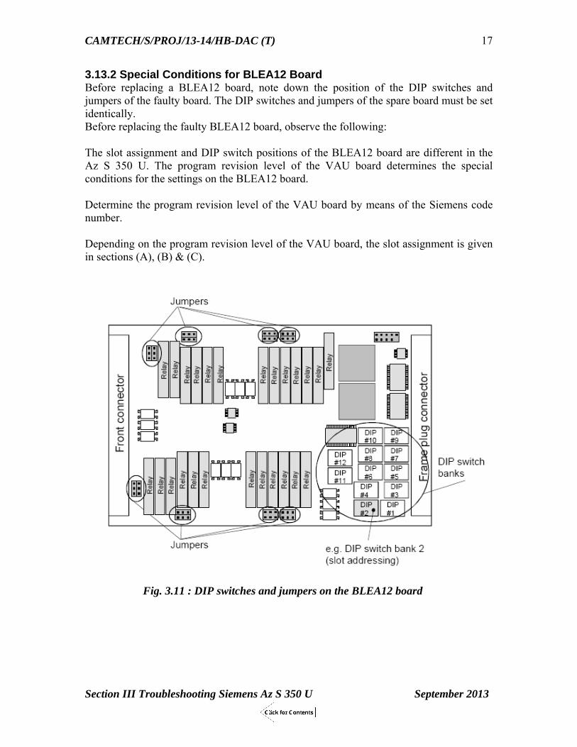
3.13.2 Special Conditions for BLEA12 Board Before replacing a BLEA12 board, note down the position of the DIP switches and jumpers of the faulty board. The DIP switches and jumpers of the spare board must be set identically. Before replacing the faulty BLEA12 board, observe the following: The slot assignment and DIP switch positions of the BLEA12 board are different in the Az S 350 U. The program revision level of the VAU board determines the special conditions for the settings on the BLEA12 board. Determine the program revision level of the VAU board by means of the Siemens code number. Depending on the program revision level of the VAU board, the slot assignment is given in sections (A), (B) & (C).
Fig. 3.11 : DIP switches and jumpers on the BLEA12 board

CAMTECH/S/PROJ/13-14/HB-DAC (T)
Section III Troubleshooting Siemens Az S 350 U September 2013
18
(A) Slot Assignment for VAU Program Revision Level <4 In this level, the BLEA 12 boards are paired as shown in figure below:
Fig.3.12.:Pairing of BLEA 12 Boards for The slot assignment and DIP switch positions must be as follows: DIP switch position (DIP switches 1 and 2 of switch bank 2)
Slot assignment
1 2 3 4 5 6 7 8 ON OFF
BLEA12 board in channel 1 (slot 11) 1st pair of BLEA12 boards
1 2 3 4 5 6 7 8 ON OFF
BLEA12 board in channel 2 (slot 63)
1 2 3 4 5 6 7 8 ON OFF
BLEA12 board in channel 1 (slot 19) 2nd pair of BLEA12 boards
1 2 3 4 5 6 7 8 ON OFF
BLEA12 board in channel 2 (slot 71)
Remove the faulty BLEA12 board. Set all DIP switches and jumpers on the spare board as on the faulty board The Fig on page shows all DIP switches and jumpers to be checked on the BLEA12 board. Insert the BLEA12 spare board in accordance with the slot assignment above.

CAMTECH/S/PROJ/13-14/HB-DAC (T)
Section III Troubleshooting Siemens Az S 350 U September 2013
19
(B) Slot Assignment for VAU Program Revision Level 4 In this level, the BLEA 12 boards are paired as shown in figure below:
The slot assignment and DIP switch positions must be as follows: DIP switch position (DIP switches 1 and 2 of switch bank 2)
Slot assignment
1 2 3 4 5 6 7 8 ON OFF
BLEA12 board in channel 1 (slot 11) 1st pair of BLEA12 boards
1 2 3 4 5 6 7 8 ON OFF
BLEA12 board in channel 2 (slot 71)
1 2 3 4 5 6 7 8 ON OFF
BLEA12 board in channel 1 (slot 19) 2nd pair of BLEA12 boards
1 2 3 4 5 6 7 8 ON OFF
BLEA12 board in channel 2 (slot 63)
Remove the faulty BLEA12 board. Set all DIP switches and jumpers on the spare board as on the faulty board The Fig on page shows all DIP switches and jumpers to be checked on the BLEA12 board. Insert the BLEA12 spare board in accordance with the slot assignment above.

CAMTECH/S/PROJ/13-14/HB-DAC (T)
Section III Troubleshooting Siemens Az S 350 U September 2013
20
(C) DIP Switch Positions for VAU Program Revision Level 5 When replacing the BLEA12 board, the DIP switch positions on switch bank 1 and switch bank 12 must be checked. This refers to the BLEA12 board in slot 11 and the BLEA12 board in slot 71 only. Remove the faulty BLEA12 board. Set DIP switch 6 of switch bank 1 of the spare board as indicated in the table below (Fig. on page shows switch bank 1 on the board).
VAU program revision level ≤4 Possible DIP switch positions of the faulty BLEA12 board
VAU program revision level ≥5 DIP switch positions of the BLEA12 spare board
BLEA12 board in channel 1 (slot 11)
BLEA12 board in channel 2 (slot 71)
BLEA12 board in channel 1 (slot 11)
BLEA12 board in channel 2 (slot 71)
1 2 3 4 5 6 7 8
ONOFF
1 2 3 4 5 6 7 8 ON
OFF
Use the same DIP switch positions
1 2 3 4 5 6 7 8 ON OFF
1 2 3 4 5 6 7 8 ON
OFF
1 2 3 4 5 6 7 8ON
OFF
Set the switches as shown
1 2 3 4 5 6 7 8ON OFF
Set the switches as shown
1 2 3 4 5 6 7 8 ON OFF
1 2 3 4 5 6 7 8 ON OFF
1 2 3 4 5 6 7 8 ON
OFF
1 2 3 4 5 6 7 8ON OFF
Use the same DIP switch positions
Set DIP switches 1 to 6 of switch bank 12 of the spare board as indicated in the table below (Fig. on page shows switch bank 12 on the board).
VAU program revision level ≤4 VAU program revision level ≥5 BLEA12 board in channel 1 (slot 11)
BLEA12 board in channel 2 (slot 71)
BLEA12 board in channel 1 (slot 11)
BLEA12 board in channel 2 (slot 71)
1 2 3 4 5 6 7 8 ON OFF
Set the switches as shown
1 2 3 4 5 6 7 8 ON OFF
Set the switches as shown
Use the same DIP switch positions as on the faulty board
Insert the spare board.
CAMTECH/S/PROJ/13-14/HB-DAC (T)
Section III Troubleshooting Siemens Az S 350 U September 2013
21
3.13.3 Special Conditions for VESBA Board When commissioning or replacing the VESBA board, the rectified voltages V1, V2 (which can be measured and adjusted on the front panel) must be adjusted to 3.0 V DC. Use a voltmeter with an internal resistance of ≥ 50 k_ for this purpose. Before switching on the evaluation computer, set the potentiometers (for V1, V2) as far to the left as they will go. After having replaced or moved the VESBA board to another slot, its proper operation must be checked by carrying out or simulating a train movement over the counting heads connected. 3.13.4 Special Conditions for DIGIDO Board The outputs of the DIGIDO board may be loaded with max. 10 mA/output. The voltage at the opto-coupler outputs may be 0 V to 5 V. 3.13.5 Special Conditions for SVK2150 Board A faulty SVK2150 power supply board may be replaced without switching off the supply voltage (interlocking power supply).

Section IV
Troubleshooting of
CEL DACF 710 A & DACF 710 P
Single Section Digital Axle Counter
CAMTECH/S/PROJ/2013-14/HB- DAC(T) SEPTEMBER 2013

Contents
Section IV -Troubleshooting - DACF 710 A & DACF 710 P CEL SSADC Clause No. Description Page No.
4.1 Introduction 1
4.2 LED indications on SSDAC unit 1
4.3 Recording of parameters 2
4.4 Troubleshooting through LED indications 5
4.5 System Error Codes 7
4.6 Reset box functions 17
4.7 Troubleshooting through Event Logger 20
4.8 Status chart of SSDAC for various conditions 29

CAMTECH/S/PROJ/13-14/HB-DAC (T)
Section IV - Troubleshooting - DACF 710 A & DACF 710 P CEL SSADC September 2013
1
Section IV Troubleshooting
DACF 710 A & DACF 710 P CEL SINGLE SECTION DIGITAL AXLE COUNTER
4.1 Introduction
The LED indications are provided on the facial plate i.e. on front side of different modules of SSDAC viz. SCC cards, MLB Cards, Modem Card, Relay Driver, DC-DC Converter and Event Logger to indicate OK or Error condition. These indications are helpful in the troubleshooting of DACF 710A & 710 P SSDAC.
4.2 LED indications on SSDAC unit SCC Cards Sr. No. LED Colour Information 1. OSC OK GREEN ON when TX coil & Oscillator are working normally.
OFF when these becomes faulty. 2. LD OK GREEN ON when signal from RX coils are normal and above
certain level, OFF when fault in RX coil or disconnection3. PULSE OK GREEN ON when signal from RX coil normal and pulse level in
Card OK. OFF when RX coil faulty, wrongly connected or disconnected
4. TP CON GREEN Permanently OFF as trolley suppression track circuit is not required in phase reversal type system.
MLB Cards Sr. No. LED Colour Information 1. 8 LED BLOCK All RED Normally OFF, ON when error appears 2. CLEAR GREEN ON for clear condition 3. OCCUPIED RED ON for occupied condition Modem Card Sr. No. LED Colour Information 1. Tx GREEN Transmitting the signal when LED is flashing. 2. RX GREEN Receiving the signal when LED is flashing 3. MODEM GREEN Normally OFF, Glows and again goes low when system is reset. 4. CD GREEN Carrier is detected when LED is flashing Relay Driver Sr. No. LED Colour Information 1. MLB 1 CLEAR GREEN ON when section clear, OFF when section occupied 2. MLB 1 CLOCK GREEN LED flashes when section is clear. 3. MLB 2 CLEAR GREEN ON when section clear, OFF when section occupied 4. MLB 2 CLOCK GREEN LED flashes when section is clear 5. RELAY DRIVE GREEN ON when section clear, OFF when section occupied.

CAMTECH/S/PROJ/13-14/HB-DAC (T)
Section IV - Troubleshooting - DACF 710 A & DACF 710 P CEL SSADC September 2013
2
Fig.5.1: Front view of SSDAC unit
DC-DC Converter Sr. No. LED Colour Information 1. +5V RED ON when +5V supply available 2. +12V RED ON when +12V supply available 3. +24V RED ON when +24V supply available 4. +15V ISO RED ON when +15V ISO supply available Event Logger Sr. No. LED Colour Information 1. RUN GREEN Blinks continuously indicating normal working of Event
Logger Card 2. LOG GREEN Blinks whenever data is being logged into the flash memory
(approx. after every 2 minutes) 3. DNLD GREEN ON when data is being downloaded from the flash memory of
the card, OFF when download is complete.
4.3 Recording of parameters For trouble-free performance of Single Section Digital Axle Counter various parameters are to be checked periodically. The various signal input and output levels and its limits which are to be recorded and adjusted to correct levels wherever necessary are given in following tables: 24 V DC Supply (Battery) Measure the DC 24 V input to the system with charger ON, charger OFF condition with all the units connected (i.e. on load) or using dummy load. S.No. Input Range near SSDAC unit
(In DC Volts) Actual measured value With Charger ON Charger OFF
1. 19.2 V to 28.8 V Note: Keep Charger OFF for 15 minutes before taking measurements.

CAMTECH/S/PROJ/13-14/HB-DAC (T)
Section IV - Troubleshooting - DACF 710 A & DACF 710 P CEL SSADC September 2013
3
Oscillator Output (TX Coils) Measure the oscillator output, frequency of TX coil of Axle detectors. S.No. Parameter Limit TX coil 1
(21 KHz) TX coil 2 (23 KHz)
1. Oscillator output 30V to 40V rms 2. Oscillator frequency (i) 20.80 to21.20 KHZ
(ii) 22.80 to 23.20 KHz
Receiver Coil Output Measure the RX coil signal output with and without dummy wheel.
Fig 5.2: Adjustment of Receiver coil with the help of dummy wheel
Fig 5.3 : Dummy wheel setting = 44 mm for 90 R, 52 kg and 60- kg rails

CAMTECH/S/PROJ/13-14/HB-DAC (T)
Section IV - Troubleshooting - DACF 710 A & DACF 710 P CEL SSADC September 2013
4
For Amplitude Modulation type Digital Axle Counter S.No. Parameter Signal Limit
mV rms Signal Measured Value
Dip 15% of signal (mV rms)
Dip measured value
1. RX Coil 1 (21 KHz) 750 - 1200 2. RX Coil 2 (23 KHz) 750 - 1200 For Phase Reversal type Digital Axle Counter S.No. Parameter Limit mV rms Measured Value 1. RX Coil 1 (21 KHz) 275 - 600 2. RX Coil 2 (23 KHz) 275 - 600 SCC Cards (Cards 1 & 2) Measure the DC voltages at monitoring sockets of SCC cards 1 & 2 with respect to ground.
Modem Output (Card 6) Check and record the modem signal output of SSDAC during normal working condition of the system.
S.No. Measuring Limit (mV rms) Measured Output (mV rms) 1. >400 mV (-6 dB)
S. No.
Card Measured output voltage (DC volts) Without dummy wheel
With dummy wheel
With push trolley (4/8 spokes) on axle detectors
Limit Meas-ured value
Limit
Meas-ured value
Limit Meas-ured value
1. SCC1 2.0 to 2.5 V
<0.7 >1.7 V
2. SCC2 2.0 to 2.5 V
<0.7 >1.7 V
Fig 5.4.: Front view of SCC 1 Card

CAMTECH/S/PROJ/13-14/HB-DAC (T)
Section IV - Troubleshooting - DACF 710 A & DACF 710 P CEL SSADC September 2013
5
DC –DC Converter Card (Card 8) Measure the DC –DC Converter output voltages with respect to respective ground for 24 V DC input fed to the SSDAC.
Relay Drive (Card 7) Check and record Relay drive output to the Vital Relay with section clear and section occupied condition. (This may be checked across R1 & R2 of relay coil in vital relay box).
S.No. Parameter Measuring Limit (DC volts) Measured output (DC volts) 1. Clear mode >20 V 2. Occupied mode <2 V
4.4 Troubleshooting through LED indications The two MLB cards continuously check and monitor the health of the system. During normal working condition of the system, all the LEDs are OFF. When the system detects error, it will be displayed on these cards by means of flashing/glowing one or more LEDs for the particular error. The errors occurring in the system during the operation of the SSDAC are encoded and are indicated by means of the 8 - LED block present on the front panel of the MLB cards. A glowing LED implies a 1 while OFF LED indicates a 0. All the LEDs are numbered as given below. DS1 to DS4 are designated for Least Significant Bits (LSB) and DS5 to DS8 are designated for High Significant Bits (HSB). The value given to each LED is given in Fig. (b) below:
S. No.
Parameter Limit (DC Volts) Measured output (DC Volts)
1. 5 V 4.75 to 5.25 V 2. 12 V 11.50 to 12.50 V 3. 24 V 23.50 to 24.50 V 4. 15 v ISO 14.50 to 15.50 V
Fig.5.5: Front view of DC-DC Converter

CAMTECH/S/PROJ/13-14/HB-DAC (T)
Section IV - Troubleshooting - DACF 710 A & DACF 710 P CEL SSADC September 2013
6
Fig. 5.6: (a) Numbering of LED indications for errors (b) Values given to each LED The Errors are given in Hexa decimal codes which can be read as given below: Example If LEDs 1 & 3 of LSB glow and LEDs 5 & 6 of HSB glow and all other LEDs are OFF. By adding LSB+HSB LED values, (1 + 4) + (10 + 20) = 35. Thus error no. is 35.
Fig. 5.7: Details of controls and indications of SSDAC unit

CAMTECH/S/PROJ/13-14/HB-DAC (T)
Section IV - Troubleshooting - DACF 710 A & DACF 710 P CEL SSADC September 2013
7
4.5 System Error Codes Details of error corresponding to the error no. and action to be taken can be seen from table below:
Indicates LED is Flashing Indicates LE is ON
Indicates LE is Blank Sr. No.
Error No.(Hex Decimal)
Process/Error Cause Action to be taken
Indications
1. 00 No error System Normal No action to be taken
2. 11 ROM test during Power On Self Test
Memory of MLB card is corrupted.
Replace the microcontroller IC or MLB card.
3. 12 RAM test during Power On Self Test
Memory of MLB card is corrupted.
Replace the microcontroller IC or MLB card.
4. 13 Serial port test during Power On Self Test
On chip serial port is corrupted.
Replace the microcontroller IC or MLB card.
5. 14 Card presence test
Any card is removed or not inserted properly.
Insert all the cards properly or replace the MLB cards
6. 15 Relay test during Power On Self Test
Relay and its connections are not proper
Check the presence of relay. Check the connections of relay. Make proper connections.

CAMTECH/S/PROJ/13-14/HB-DAC (T)
Section IV - Troubleshooting - DACF 710 A & DACF 710 P CEL SSADC September 2013
8
Sr. No.
Error No.(Hex Decimal)
Process/Error Cause Action to be taken
Indications
7. 21 ROM Test fail during system working
Memory of MLB card is corrupted.
Replace the microcontroller IC or MLB card.
8. 22 RAM Test fail during system working
Memory of MLB card is corrupted.
Replace the microcontroller IC or MLB card.
9. 24 Card presence test during system working
Any card is removed or not inserted properly.
Insert all the cards properly or replace the MLB cards
10. 30 Link error Link between two SSDAC units is open or loss of Carrier Detect (CD).
Check the communication link between the units and rectify the fault.
11. 31 Sequence error Sequence of pulse not correct when axle is detected on the sensor.
Check the arrangement of the detectors. It shall be at proper height from top of rail. Check card 1 & 2 and replace if necessary.

CAMTECH/S/PROJ/13-14/HB-DAC (T)
Section IV - Troubleshooting - DACF 710 A & DACF 710 P CEL SSADC September 2013
9
Sr. No.
Error No.(Hex Decimal)
Process/Error Cause Action to be taken
Indications
12. 32 Self count mismatch
Difference in counts of the two MLB cards in local unit after detection of all the axles passed over the axle detectors.
Reset the system. If error persists replace the MLB cards with the spare cards. Send the cards for repair.
13. 33 IN/OUT error The number of axles going OUT of the section is more than coming INTO the section. This error is also displayed after reset is applied and while the system is trying to synchronize, there is train movement in the section.
Check the system for error and apply reset to normalize the system.
14. 34 OUT before IN error
The system is in preparatory state and train exits from the section without entering into the section.
Check the axle detectors A. Check SCC1 card & replace if found faulty.
15. 35 Negative count error
Counts OUT of the section are more than the counts INTO the section.
Check signals dip at both locations in single line section. Check signals dip and coil position at entry end in double line block section. Check DC voltage in SCC 1 & 2 cards.

CAMTECH/S/PROJ/13-14/HB-DAC (T)
Section IV - Troubleshooting - DACF 710 A & DACF 710 P CEL SSADC September 2013
10
Sr. No.
Error No.(Hex Decimal)
Process/Error Cause Action to be taken
Indications
16. 36 Shunt error Train moving forward & backwards (shunting) on axle detectors without proper direction influencing only external detector twice without affecting internal detector.
Station master has to apply reset after section is verified as per SWR. Movement of pilot train in the section makes system clear.
17. 37 Supervisory error
Any of the axle detector signals becomes low.
Check the Tx & Rx signal level of the axle detectors. It should be as per the recorded readings. Check the SCC 1 & 2 card DC voltages. Adjust or replace if any of the above is not OK.
18. 38 Internal shunt error
When train is moving forward & backwards (shunting) on axle detectors without proper direction in such a way that both detectors are influenced and internal detector is influenced twice.
Station master has to apply reset after section is verified as per SWR. Movement of pilot train in the section makes system clear.

CAMTECH/S/PROJ/13-14/HB-DAC (T)
Section IV - Troubleshooting - DACF 710 A & DACF 710 P CEL SSADC September 2013
11
Sr. No.
Error No.(Hex Decimal)
Process/Error Cause Action to be taken
Indications
19. 39 Count unequal error
Mismatch of counts by both MLB cards.
If the error is continuously displayed, replace the MLB cards.
20. 40 Communication error
Communication between the two units is not proper i.e. packet information is corrupted due to noise in the Quad Pair used.
Check the pair used for the communication. Check that no parallel wires are used for modem communication. Check that correct Quad pair is used for communication. If problem persists, replace the spare pair.
21. 41 CRC error Data of the packets got corrupted thereby CRC of the packet not matching.
Check the pair used for communication. Check that no parallel wires are used for modem communication. Check the correct Quad pair is used for communication. If problem persists replace the spare pair or improve the earthing to the unit.

CAMTECH/S/PROJ/13-14/HB-DAC (T)
Section IV - Troubleshooting - DACF 710 A & DACF 710 P CEL SSADC September 2013
12
Sr. No.
Error No.(Hex Decimal)
Process/Error Cause Action to be taken
Indications
22. 42 EOB error Data of the packets got corrupted thereby End of packet information is not detected.
Check link between the two units. Check the modem cards and apply reset in the system.
23. 43 Wheel shunt error
Sequence of pulses from the axle detectors and SCC cards is disturbed
Check whether the position of axle detectors is OK and correct. Check for failure due to motor trolley, perforated push trolley, dip lorry, etc and apply reset in the system.
24. 44 Independent pulses error
If the wheel is moved in such a way that independent pulses are generated by system in FORWARD direction. This happens only if motor trolley wheel that are similar in diameter is moved beyond the permissible limit.
Check whether the position of axle detectors is OK and correct. Check for failure due to motor trolley, perforated push trolley, dip lorry, etc and apply reset in the system

CAMTECH/S/PROJ/13-14/HB-DAC (T)
Section IV - Troubleshooting - DACF 710 A & DACF 710 P CEL SSADC September 2013
13
Sr. No.
Error No.(Hex Decimal)
Process/Error Cause Action to be taken
Indications
25. 45 Independent pulses error
If the wheel is moved in such a way that independent pulses are generated by system in REVERSE direction. This happens only if motor trolley wheel that are similar in diameter is moved beyond the permissible limit.
Check whether the position of axle detectors is OK and correct. Check for failure due to motor trolley, perforated push trolley, dip lorry, etc and apply reset in the system.
26. 46 Exit mismatch error
The section occupancy and section clearance by different type of wheel i.e. section is occupied by train but clears by motor trolley wheel and vice versa.
Reset the system.
27. 47 Train trolley mismatch error
Following Motor trolley shunts back or if only train entered the section and crossed exit and leaving two counts, now motor trolley leaves section balancing counts.
Reset the system.

CAMTECH/S/PROJ/13-14/HB-DAC (T)
Section IV - Troubleshooting - DACF 710 A & DACF 710 P CEL SSADC September 2013
14
Sr. No.
Error No.(Hex Decimal)
Process/Error Cause Action to be taken
Indications
28. 48 Non overlap pulses before overlap pulses error
If motor trolley enters the section and after that train enters the section
Reset the system
29. 50 Relay removed (physically from plug board)
During power on self test (POST) of the system the presence of relay is not detected.
Check the presence of Vital relay in the relay box of the system & insert in the plug board.
30. 51 Relay contacts failure in occupied state
When section is occupied and the back contact of the vital relay is found open.
Check the back contacts (D5 & D6) of the vital relay used for read back in the system & rectify.
31. 52 Relay contacts failure in unoccupied state (clear)
When section is clear after passage of train but front contact of vital relay is found open.
Check the pick up contacts of the vital relay and rectify or replace the relay.
32. 53 Relay drop failure in occupied state
The system after detection of train in the section goes to OCCUPIED state but vital relay fails to drop
Check the back contacts of the relay and rectify or replace the relay.
33. 60 Tracing error Both MLBs work in tandem and software follow a particular sequence, but any sequence is missed.
Replace the MLB card which is displaying the error.

CAMTECH/S/PROJ/13-14/HB-DAC (T)
Section IV - Troubleshooting - DACF 710 A & DACF 710 P CEL SSADC September 2013
15
Sr. No.
Error No.(Hex Decimal)
Process/Error Cause Action to be taken
Indications
34. 61 Secondary CPU error
If MLB1 detects that the adjacent MLB2 is in different state or vice versa.
Apply reset to normalise the system
35. 62 Secondary CPU fails
When MLB card detects the adjacent MLB card is faulty.
The adjacent MLB card is faulty. Replace the adjacent MLB card with spare card.
36. 66 Watchdog Reset
Power supply is interrupted thereby DC-DC converter voltages are also interrupted in the system.
Check the power supply to the system and rectify.
37. 70 Configuration error during self test
The unit address of any unit is disturbed or both units have the same address.
Check and install the Entry and Exit Units with correct address setting in the section.
38. 71 J packet configuration error
The unit address of any unit is disturbed or both units have the same address.
Check and install the Entry and Exit Units with correct address setting in the section.
39. 72 R packet configuration error
The unit address of any unit is disturbed or both units have the same address.
Check and install the Entry and Exit Units with correct address setting in the section.

CAMTECH/S/PROJ/13-14/HB-DAC (T)
Section IV - Troubleshooting - DACF 710 A & DACF 710 P CEL SSADC September 2013
16
Sr. No.
Error No.(Hex Decimal)
Process/Error Cause Action to be taken
Indications
40. 73 Configuration error during normal working
The address of unit is disturbed/changed while the system is running.
Rectify the unit address as per the factory setting. Reset is applied.
41. 74 U packet configuration error
The unit address of any unit is disturbed or both units have the same address.
Check and install the Entry and Exit Units with correct address setting in the section.
42. 80 Remote error The remote unit is in error state. The local unit is OK
Check the errors in remote unit and rectify.
43. 7F Remote Reset error
The remote unit has been reset.
Apply reset in the local unit or else apply reset in both SSDAC units.
44. 3F Self Reset error The local unit is reset and is waiting for remote unit to be reset.
Remote unit is to be reset or else both SSDAC units are to be reset.
Other type of errors Sr. No.
Condition Error No.
System status Action required
1. Entry counts are more than Exit counts
No Error Vital relays are dropped. System may fail for each train movement.
1. Check Exit end axle detectors and align them properly.
2. Check SCC1 & 2 cards and its output

CAMTECH/S/PROJ/13-14/HB-DAC (T)
Section IV - Troubleshooting - DACF 710 A & DACF 710 P CEL SSADC September 2013
17
4.6 Reset box functions The reset box has the following components 1. The LED indications displaying the section status
(a) Section Clear GREEN indication LED of 10mm. (b) Section Occupied RED indication LED of 10mm. (c) Power ON YELLOW indication of 3mm. (d) Prep. Reset GREEN indication of 3mm. (e) Line Verification YELLOW indication of 3mm.
2. SM s Key actuator 3. Push Button RED colour 4. Counter for recording the number of reset operations. 5. Alphanumeric 20 X 2 row LCD display with Backlit for
(a) Axle Counts of Local and Remote unit (b) Error Code in Numeric format (c) Section Status (d) Last 10 Errors with date and time
6. 4 Keys Keypad for setting the date and time operation. 7. 9 pin D-sub connector is given on the motherboard of reset box which can be used for downloading the data from flash for analysis purpose. 8. Miniature reset switch for refreshing the LCD display. The reset box is connected in the Station master’s room and is used for applying the reset by station master.

CAMTECH/S/PROJ/13-14/HB-DAC (T)
Section IV - Troubleshooting - DACF 710 A & DACF 710 P CEL SSADC September 2013
18
The following processes take place in the working of reset box: (i) During POWER ON of reset box, the reset box will display the Software version of
the SSDAC software used and its checksum.
(ii) After the checksum, the reset box will wait for the user to apply the reset to SSDAC
system. The screen will display RESET THE SYSTEM .
(iii) The reset shall be applied as defined in the resetting procedure given below. On
pressing of Reset button and SM s Key, the PREPRESET indication will start flashing. The remote unit also required to be reset. When reset is applied to both the local and remote SSDAC units, the flashing PREP reset indication will become Steady when the system attains the Preparatory state. At this point the LCD will display the following message.
(iv) When Pilot train is moved in the section, the LCD will display the axle counts in
local DP on the Entry side Reset Box and in Remote DP on the Exit side Reset Box as shown below. The section status is displayed as Preparatory state.

CAMTECH/S/PROJ/13-14/HB-DAC (T)
Section IV - Troubleshooting - DACF 710 A & DACF 710 P CEL SSADC September 2013
19
(v) When Pilot train is moved out of the section, The LCD displays the axle counts in Remote DP on the Entry side reset Box and in Local DP on the exit side reset Box. When the axle counts are matched, the section status is displayed as Clear and Section CLEAR indication glows.
(vi) The axle counts are incremented or decremented according to the direction of train movements. In case of failure, Error code is displayed at both the ends. The Error code along with its description is displayed. This Error code is required to be recorded by SM s before applying Reset.
(vii) On applying the reset, this Error code will get refreshed and is stored in flash. List
of 10 recent error codes are stored in Error log entry. This Error Log can be viewed by maintainer at all times without the use of PC. By pressing reset button for 10 secs, last 10 Errors will be displayed with Date and time one by one. After the complete Error log, the LCD display will come back to its original state. This Error log can be activated at any time but is recommended not to done during the reset procedure.
(viii) One reset switch is provided on the interface card or motherboard which can be used for resetting the display of LCD. This switch can be accessed by removing the top cover of the reset box. This reset will not affect the status of the section and be applied at any time but it is recommended to not to use it during the reset operation.
(ix) In case the cable pair from location box to SSDAC unit is not provided, the display information on the reset box will not appear.

CAMTECH/S/PROJ/13-14/HB-DAC (T)
Section IV - Troubleshooting - DACF 710 A & DACF 710 P CEL SSADC September 2013
20
4.7 Troubleshooting through Event Logger Event logger card is designed to capture and store important signals from the remote and local SSDAC units. The stored data can be downloaded from the event logger card for the purpose of analyzing the events occurring during the operations of the SSDAC. The data can be analyzed with the help of CEL data analyzer software. Following signals are captured by the event logger card.
Card removal information Serial packets from MLB1 (Local unit) MLB2 (local unit) Remote unit (communication failure and composite information from MLB1 &
MLB2) For capturing the signals of SSDAC unit, Event Logger card is required to be plugged in the SSDAC unit in the appropriate slot
4.7.1Data Analyzer Software For analyzing the data stored in flash of the event logger card, EL card is connected to a PC (or laptop) through a COM PORT (or USB port) using a standard cross connected RS-232 cable (or USB to RS232 converter cable). Data download procedure Data analyzer software is installed in a PC using Auto run facility in the software CD or running setup.exe command. After the software is installed, run the software for carrying out various EL related activities. From Main menu, Card function option is selected. a) COM port setting: Select COM port Settings from the drop down menu of card function
(use default setting for the selected Com Port as 19200, n, 8, 1). b) Select desired Com Port, click OK.
4.7.2 Other card functions Check CRC: For checking the checksum stored in the micro-controllers of MLB cards. To check the CRC, data must be downloaded first from the event logger card. Reset flash: For resetting the flash, click on reset flash. Erase flash: To erase all 4096 pages of the flash memory, click on to “Erase flash” and then click on to “Erase” button. “Flash erased” message will be displayed on the host computer screen. Further writing of the flash memory will start from page number 0.Before erasing the flash, time stamping is recommended.

CAMTECH/S/PROJ/13-14/HB-DAC (T)
Section IV - Troubleshooting - DACF 710 A & DACF 710 P CEL SSADC September 2013
21
Time stamping: Click on to the “Time stamping” option. Click on the “Select the current time” Click on “Form packet”. Click on “Send packet”, time packets are sent to the event logger card. Show current time stamping: Once clicked on this option the system shows the current time stamping. The date time will appear in the following format: {15:03:2005|12:27:00}
4.7.3Downloading data Data from the Event Logger card is downloaded from flash memory of event logger. Case 1: When flash page number is >0 and flash is not circulated, the controller generates a message downloading buffer followed by page number of current page. Once the command is executed, data is downloaded from the flash memory from page number 0 to the current page number. Case 2: When flash is circulated, the controller generates a message downloading buffer followed by page number of current page. Here in this case data is downloaded from current page to last page (4096) of the flash and then page number 0 to the current page number. Steps for downloading the data. Open the CEL data analyzer application. Go to Start > All Programs > Data Analyser- SSDAC > Data analyser-SSDAC
Go to card function.
Click on the com port setting

CAMTECH/S/PROJ/13-14/HB-DAC (T)
Section IV - Troubleshooting - DACF 710 A & DACF 710 P CEL SSADC September 2013
22
Click on com1/com2/com3/com4 as per the comport availability.
Check the setting for 19200 bauds, parity none, data bits 8 and stop bit 1.
Now click on to download data. Give file name and save. Data starts getting downloaded.
On completion of downloading the message downloading completed appears.

CAMTECH/S/PROJ/13-14/HB-DAC (T)
Section IV - Troubleshooting - DACF 710 A & DACF 710 P CEL SSADC September 2013
23
Forced download: In forced download; we get complete flash data from page 0 to page 4096 irrespective of restored page number and loop number. This is given to download data if flash pointer is restored and one is interested for the old data. But this will always download data from page 0 to page 4096.
4.7.4Data analysis Run the Data Analyzer Application Click on select data, then select file form the list or from the path where the files are saved. Give name of station or station code. Station name / code should be at least 3 characters long. Click on OK button. Then files will start getting created. After creating the files message will appear “Files are created and now you can analyze the data”.
The required time slots in “From” and “To” windows for which the analyzing is to be done should be selected. After time zone selection, click on VIEW, The result menu comes on having information regarding serial packets and Card removal information.

CAMTECH/S/PROJ/13-14/HB-DAC (T)
Section IV - Troubleshooting - DACF 710 A & DACF 710 P CEL SSADC September 2013
24
Current Report and Error Report for the selected *.dat file are ready to be viewed. The current report can be exported in the Excel format by clicking on “Export to Excel” button. If Microsoft Excel is not installed in the PC or Laptop, then the user can use the Print button to print the report directly or the “Save Report button” to save the report in a text file.
Search feature is provided in data analyzer software to search and analyze the data on the basis of time stamps or error codes.
Detailed help instructions are provided in the help menu of the software.

CAMTECH/S/PROJ/13-14/HB-DAC (T)
Section IV - Troubleshooting - DACF 710 A & DACF 710 P CEL SSADC September 2013
25
4.8 Status chart of SSDAC for various conditions The status includes when power connected, Reset applied, Preparatory, Occupied (Train Entry in Section), Clear (Train Exit from Section). S. No.
Condition Station A Station B SM’s Room (Reset Box)
Relay Room
Location SM’s Room (Reset Box)
Relay Room
Location
Q-Relay Status
Q-Relay Status
System Status
Q-Relay Status
Q-Relay Status
System Status
1. 24 V DC is connected at Station A (Fuse connected)
Occupied (RED) LED indication glows
PPR VPR
PR VR
24V DC is available to system. System is ON & waiting for Reset.
No indication
PPR VPR
PR VR
System is OFF
2. 24 V DC is connected at station B (Fuse connected)
- do - - do - -do- -do- Occupied (RED) LED indication glows
-do- -do- 24 V DC is available to the system. System is ON. Waiting for Reset.
3. Reset applied at station A
(i) Inserted SM’s Key, turned and kept pressed.
(ii) Reset button pressed
(iii) Both
PPR VPR
PR VR
(i) Reset is applied to system.
The self test starts in the system and goes to error due to far
-do- -do- -do- -do-

CAMTECH/S/PROJ/13-14/HB-DAC (T)
Section IV - Troubleshooting - DACF 710 A & DACF 710 P CEL SSADC September 2013
26
S. No.
Condition Station A Station B SM’s Room (Reset Box)
Relay Room
Location SM’s Room (Reset Box)
Relay Room
Location
Q-Relay Status
Q-Relay Status
System Status
Q-Relay Status
Q-Relay Status
System Status
released. (iv) Occupied
(RED) indication remains.
end unit is not released
4. Reset applied at Station B
Occupied (Red) LED indication glows.
PPR VPR
PR VR
Error due to far end unit is not
synchronized.
i) Insert SM's key, turned & keep pressed ii) Reset button pressed. iii) Occupied
indication remains.
PPR VPR
PR VR
i) Reset is applied to system. ii) The self test starts in the system and hand shakes with the other end unit.
5. System enters Preparat ory reset mode
Power On remains OCC indication remains. Preparatory Reset indication glows. Reset counter
PPR* VPR
PR* VR
Both Units communicateeach other by means of packets and enters into
preparatory reset mode
Power ON remains. OCC Indication remains. Preparatory Reset Indication
glows
PPR VPR
PR VR
Both Units Communicates with each other by means of packets and enters into preparatory state mode. Reset counter

CAMTECH/S/PROJ/13-14/HB-DAC (T)
Section IV - Troubleshooting - DACF 710 A & DACF 710 P CEL SSADC September 2013
27
S. No.
Condition Station A Station B SM’s Room (Reset Box)
Relay Room
Location SM’s Room (Reset Box)
Relay Room
Location
Q-Relay Status
Q-Relay Status
System Status
Q-Relay Status
Q-Relay Status
System Status
increments by 1 count.
increments by 1 count
*After PR & PPR relays are picked up, the system is in No. Error Condition, But, the VR & VPR Relays of both stations are forced to remain in dropped condition by the system. Therefore LSS cannot be lowered. The 1st train is to be piloted in the section to register balance of counts and thereby to drive VR relays ON at both stations. 6. 1st train
enters the block section from stn A
Power On LED (Yellow) remains. Occupied (Red) LED remains. Prep Reset LED remains ON.
PPR VPR
PR VR
System registers wheel counts & PR relays remains pickup.
Power On LED glows. Prep. Reset LED remains ON.
PPR VPR
PR VR
System registers wheel counts at station A. PR & PPR relays remains picked up.
7. 1st train clears the section from Stn B.
Power On LED glows. Prep. Reset LED becomes OFF. Occupied LED becomes OFF & clear LED glows
PPR VPR
PR VR
Counts in both units of the system become equal. The decision to drive VR relay ON is given. VR relay picks up.
Power on LED glows. Prep. Reset LED becomes OFF. Occupied LED becomes OFF & clear LED becomes ON
PPR VPR
PR VR
Counts in both units of the system become equal. The decision to drive VR relay ON is given. VR relay picks up.
8. On Power on LED PPR PR System Power on PPR PR System

CAMTECH/S/PROJ/13-14/HB-DAC (T)
Section IV - Troubleshooting - DACF 710 A & DACF 710 P CEL SSADC September 2013
28
S. No.
Condition Station A Station B SM’s Room (Reset Box)
Relay Room
Location SM’s Room (Reset Box)
Relay Room
Location
Q-Relay Status
Q-Relay Status
System Status
Q-Relay Status
Q-Relay Status
System Status
subsequent trains entry in the block sectio
glows. Prep. Reset LED is OFF. Occupied LED becomes ON. Clear LED becomes OFF.
VPR VR registers in counts at station A. System goes to OCC state. VR is driven OFF.
LED glows. Prep. Reset LED is OFF. Occupied LED becomes ON. Clear LED becomes OFF.
VPR VR registers in counts at stn A. System goes to OCC state. VR is driven OFF.
9. Trains clears the block section and enters stn B
Power on LED glows. Prep. Reset LED is OFF. Occupied LED becomes OFF. Clear LED becomes ON.
PPR VPR
PR VR
System registers out counts at station B. After count balancing the system goes to clear state
Power on LED glows. Prep. Reset LED is OFF. Occupied LED becomes OFF. Clear LED becomes ON.
PPR VPR
PR VR
System registers out counts at stn B. After count balancing the system goes to clear state.
Note: In the wiring circuit of Reset Box contacts of PPR & VPR are not proved. Hence reset voltage is extended to system in
PPR or VPR pick up condition. Reset is however possible only in error or occupied state after registration of at least one out count.

CAMTECH/S/PROJ/13-14/HB-DAC (T)
Section IV - Troubleshooting - DACF 710 A & DACF 710 P CEL SSADC September 2013
29
4.9 Relay status chart Sr. No.
Condition Station A Station B Relay room Location Relay room Location
1. 24 V connected VPR PPR VR PR VPR PPR VR PR
2. Reset applied (SM s key inserted, reset button operation, etc)
VPR PPR VR PR VPR PPR VR PR
3. System enters preparatory reset mode
VPR PPR VR PR VPR PPR VR PR
4(a) First train enters the section (Pilot train)
VPR PPR VR PR VPR PPR VR PR
4(b) First train clears the section (after counts equal in both units
VPR PPR VR PR VPR PPR VR PR
5(a) Subsequent trains when occupy the section
VPR PPR VR PR VPR PPR VR PR
5(b) Subsequent trains when clears the section
VPR PPR VR PR VPR PPR VR PR

Section V
Troubleshooting of
SSDAC-G36 G.G.Tronics Single Section Digital Axle Counter
CAMTECH/S/PROJ/2013-14/HB- DAC (T)
September 2013

Contents
Section V - Troubleshooting of SSDAC-G36 G.G.Tronics Single Section Digital Axle Counter
Clause No. Description Page No.
5.1 Introduction 1
5.2 Modules of G36 SSDAC 1
5.3 Configurations 1
5.4 Reset Box 1
5.5 Power Supply Arrangement 2
5.6 Protective devices 3
5.7 Maintenance 3
5.8 Troubleshooting 5

CAMTECH/S/PROJ/13-14/HB-DAC (T)
Section V - Troubleshooting - G-36 G.G.Tronics SSDAC September 2013
1
Section V Troubleshooting of
SSDAC-G36
G.G.Tronics Single Section Digital Axle Counter
5.1 Introduction SSDAC G36 manufactured by M/s G.G.Tronics India Pvt. Ltd., is a microcontroller based system with 2 out of 2 architecture suited for proving station and block section. 5.2 Modules of G36 SSDAC The hardware and software for all the configurations are same. The main modules for SSDAC-G36 are listed below:
SSDAC unit Reset box Axle Detectors (Tx & Rx coils factory tuned to 21 KHz & 25 KHz with
associated cables of 15 Mtrs.each) 5.3 Configurations SSDAC-G36 units can be installed to work in the following configurations:
Two detection points Single section: In straight line [2DP1S]. Three detection points Single section: In point zone [3DP1S]. Three-detection points for two consecutive sections in a straight line [3DP2S].
5.4 Reset Box
The Reset Box has the following controls and displays.
SM Key – This has a facility of locking to prevent unauthorized operations. For executing a reset command, this key has to be kept pressed after unlocking it.
Fig. 3.4.: Reset box front view

CAMTECH/S/PROJ/13-14/HB-DAC (T)
Section V - Troubleshooting - G-36 G.G.Tronics SSDAC September 2013
2
Reset Push Button – This switch is meant for sending the reset command to the system. For sending the reset command, both the SM Key and the reset push button are to be held pressed simultaneously and momentarily. Line Verification Box Line verification Box is supplied only for case where hard reset has to be adopted instead of a preparatory reset.
Indications One 10 mm Green and Red LED are provided for indicating status of block section. One 5 mm green LED for indicating the status of preparatory reset. Flashing- when local reset is applied. Steady - when reset is applied at the other end also & the system is waiting for pilot train. OFF – when the section becomes clear. One 5 mm Yellow LED for indicating the line verification status. Normally OFF; glows only when line verification key is operated for executing direct reset. One 5 m Yellow LED for indicating power ON condition. Counter One 6 digit non-resettable counter is provided which increments after each resetting operation. Display One LCD display with 4 lines & 40 characters gives display of events, System Status, Checksum and Version No, Counts and error code. The reset box is connected to the system with one pair of quad cable for FSK communication and 12 core signal cable for transfer of reset commands and reception of the signals from the system.
The reset box required may be one per unit or two per unit depending upon the configurations. Process of resetting required for a particular configuration also differs. For example a single stationmaster or two separate stationmasters can do reset.
5.5 Power Supply Arrangement
The SSDAC system works on 24V DC supply. This has to be provided by the respective station through power cables. The continuous current drain, requirement of battery and battery charger are as indicated in Table below: S. No. Configuration Continuous
current drain Battery capacity Charger capacity
1. 2DP1S version < 2 Amp. 24 V/40 A.H. – 1 set 5 Amp. – 2 Nos. 2. 3DP1S version < 3 Amp. 24 V/40 A.H. – 1 set 5 Amp. – 1 No. 3. 3DP2S version < 3 Amp. 24 V/40 A.H. – 3 sets 5 Amp. – 3 Nos.
Input supply to be maintained between 22 V and 26 V DC.

CAMTECH/S/PROJ/13-14/HB-DAC (T)
Section V - Troubleshooting - G-36 G.G.Tronics SSDAC September 2013
3
5.6 Protective devices The details of protective fuses and surge arrestors are as given below: Table A -Fuses
Path FTB Point Rating Quantity Input 24 V DC Power supply to system 1,2 6.3 Amps 2 Nos. on + limbs Spare 5,6,7,8 6.3 Amps 4 Nos. DC 24 V supply to Relay Box 11,12,13,14 6.3 Amps 4 Nos. Connection from System to Relay box 15 to 22 2 Amps 8 Nos. Connection to VPR & PPR relays in Relay room
23,24,25,26 2 Amps 4 Nos.
Quad cable to system 27,28 2 Amps 2 Nos. To reset box in the station 35,36,43,44 2 Amps 4 Nos. Tx/Rx coil connections 51 to 58 2 Amps 8 Nos.
Table B - LDUs (Lightening Discharge Protection Units)
Path Type Quantity Input 24 V DC Power Supply to System 24 V DC 1 No. Termination of Quad cable to System 24 V DC 1 No. Quad cable from System to Reset Box 24 V DC 1 No. Quad cable from Reset Box to System for reset 48 V DC 1 No.
5.7 Maintenance
Adjustments required in the field The adjustment has to be done after measuring the voltages at monitoring points provided on different modules, tabulated in the Table C. Output voltages of DC-DC Converter Measure the input voltage of 24 V DC between GND and the corresponding input monitoring point; this should be within 22 V and 26 V DC. With the same GND measure the other voltages. Adjust +5V precisely to 5V with the help of potentiometer provided for the purpose on the front plate of DC-DC Converter. Similarly adjust +18V fed to the PD card.
Settings in PD cards for different voltages In the PD cards adjustment facility is provided for Rx signal, Supervisory signal and phase adjustment of Rx with respect to Tx. All the adjustments have to be carried out under no wheel condition and the voltages are to be as indicated in Table D. Adjustments have to be carried out on each of the 21 KHz & 25 KHz PD cards individually.

CAMTECH/S/PROJ/13-14/HB-DAC (T)
Section V - Troubleshooting - G-36 G.G.Tronics SSDAC September 2013
4
Table C: Monitoring points of SSDAC Module Monitoring item Measured values
range DC-DC Converter
+5V DC and GND 4.75V to 5.25 V +18V DC and GND 17.75V to 18.25 V +12V DC and GND 11.75V to 12.25 V -12V DC and GND 11.75V to 12.25 V +24V DC and GND 22V to 26V
CPU1 EN1B O/P and GND (For SF, CF, 3DP1S units)
11.5V to 12.5V DC
EN1A O/P and GND (For EF, CF) 11.5V to 12.5V DC CPU2 EN2B O/P and GND
(For SF, CF, 3DP1S units) 11.5V to 12.5V DC
EN2A O/P and GND (For EF, CF) 11.5V to 12.5V DC RELAY DRIVE 1 (For EF,CF)
VITAL RELAY A O/P(+) VITAL RELAY A O/P(-)
>20V DC
RELAY DRIVE (For SF,CF,3D units)
VITAL RELAY B O/P(+) VITAL RELAY B O/P(-)
>20V DC
Table D – Settings of PD cards Module Monitoring point Expected values
Without wheel With wheel Phase Detector (PD1 and PD2)
RX-SIG and GND (Rx Adj.) 900 mV to 1.2 V AC < 350 mV AC SUP-OUT and GND 4V to 5V DC 3 V to 3.9 V DC WHEEL-M-OUT and GND 4.5V to 5V DC 3 mV to 5 mV DC WHEEL-S-OUT and GND 4.5V to 5V DC 3 mV to 5 mV DC RX-PH-SIG and GND (PH Adj.)
10V to 12V DC 0.1 or 0.2 V (Min.)
SUP-ADJ and GND (SUP Adj.)
4V to 5V DC 3 V to 3.9 V DC
Wheel influencing both detectors
-- < 2 V in both PD cards
Note: (i) The above monitoring points should be checked monthly. (ii) For measuring AC voltages of Tx/Rx coils and at Phase Detector terminals, it is
essential that a true RMS voltmeter with Digital Multi-meter of 100 kHz bandwidth like Fluke model 187 or higher and their equivalents of other manufacturers is used for getting proper readings.
(iii) Presence of train wheel condition is to be created with the help of dummy wheel.

CAMTECH/S/PROJ/13-14/HB-DAC (T)
Section V - Troubleshooting - G-36 G.G.Tronics SSDAC September 2013
5
Fig. 3.5.: SSDAC 36 unit with LCD display 5.8 Troubleshooting
For ease of maintenance in the field messages are provided in the Display Module both during healthy and Error conditions
About 61 possible conditions have been identified which drives the system into Error mode.
The errors are displayed in plain English on the Display Module Many Error Messages are displayed that suggest faulty module to take immediate
corrective action by the service personnel. Detail report can be downloaded from Event Logger card for analysis and the corrective action to be taken
Troubleshooting chart Error Code on display of CPU
Errors Analysis Corrective measure
1 PD1_BOARD_MISSING Error occurred due to missing of the Phase detector 1 module (PD1- 21KHz) during run time and boot time diagnosis
Place the PD1 module in the slot and reset the system
2 PD2_BOARD_MISSING Error occurred due to missing of the Phase detector 2 module (PD2- 25KHz) during run time and boot time diagnosis.
Place the PD1 module in the slot and reset the system
3 SM_CPU_MISSING Error occurred due to missing of the SM-CPU module during run time and boot time diagnosis.
Place the SM-CPU module in the slot and reset the system
4 MODEM_MODULE_A_MISSING Error occurred due to Place the
LCD Status Display
PD
CPU
24VDC Power
Relay Drive
Event Logger
Communication Card

CAMTECH/S/PROJ/13-14/HB-DAC (T)
Section V - Troubleshooting - G-36 G.G.Tronics SSDAC September 2013
6
Error Code on display of CPU
Errors Analysis Corrective measure
missing of the Communication A module during run time and boot time diagnosis.
Communication A module in the slot and reset the system
5 MODEM_MODULE_B_MISSING Error occurred due to missing of the Communication B module during run time and boot time diagnosis
Place the Communication B module in the slot and reset the system
6 RELAY_DRIVE_A_MISSING Error occurred due to missing of the Relay Drive A module during run time and boot time diagnosis
Error occurred due to missing of the Relay Drive A module during run time and boot time diagnosis
7 RELAY_DRIVE_B_MISSING Error occurred due to missing of the Relay Drive B module during run time and boot time diagnosis
Place the Relay Drive B module in the slot and reset the system
8 PEER_CPU_MISSING Error occurred due to missing of the any one of the CPU module during run time and boot time diagnosis
Place the CPU module missing in the slot and reset the system
9 COMM_LU1_TO_US1_FAILURE When EF CPU1 could not transmit to remote unit (CF or SF) CPU1
Check the communication links (MS Coupler) and Reset the system
10 COMM_LU1_TO_US2_FAILURE When EF CPU1 could not transmit to remote unit (SF or CF) CPU2
Check the communication links (MS Coupler) and Reset the system
11 COMM_LU1_TO_DS1_FAILURE When SF CPU1 could not transmit to remote unit (CF or EF) CPU1
Check the communication links (MS Coupler) and Reset the system
12 COMM_LU1_TO_DS2_FAILURE When SF CPU1 could not transmit to remote unit (CF or EF) CPU2
Check the communication links (MS Coupler) and Reset the system
13 COMM_US1_TO_LU1_FAILURE When EF CPU1 could Check the

CAMTECH/S/PROJ/13-14/HB-DAC (T)
Section V - Troubleshooting - G-36 G.G.Tronics SSDAC September 2013
7
Error Code on display of CPU
Errors Analysis Corrective measure
not receive any response from the remote unit (SF or CF) CPU1
communication links (MS Coupler) and Reset the system
14 COMM_US2_TO_LU1_FAILURE When EF CPU2 could not receive any response from the remote unit (SF or CF) CPU1
Check the communication links (MS Coupler) and Reset the system
15 COMM_DS1_TO_LU1_FAILURE When SF CPU1 could not receive any response from the remote unit (CF or EF) CPU1
Check the communication links (MS Coupler) and Reset the system
16 COMM_DS2_TO_LU1_FAILURE When SF CPU2 could not receive any response from the remote unit (CF or EF) CPU1
Check the communication links (MS Coupler) and Reset the system
17 COMM_LU2_TO_US1_FAILURE When EF CPU2 could not transmit to remote unit (SF or CF) CPU1
Check the communication links (MS Coupler) and Reset the system
18 COMM_LU2_TO_US2_FAILURE When EF CPU2 could not transmit to remote unit (SF or CF) CPU2
Check the communication links (MS Coupler) and Reset the system
19 COMM_LU2_TO_DS1_FAILURE When SF CPU2 could not transmit to remote unit (CF or EF) CPU1
Check the communication links (MS Coupler) and Reset the system
20 COMM_LU2_TO_DS2_FAILURE When SF CPU2 could not transmit to remote unit (CF or EF) CPU2
Check the communication links (MS Coupler) and Reset the system
21 COMM_US1_TO_LU2_FAILURE When EF CPU1 could not receive any response from the remote unit (SF or CF)
Check the communication links (MS Coupler) and Reset the system

CAMTECH/S/PROJ/13-14/HB-DAC (T)
Section V - Troubleshooting - G-36 G.G.Tronics SSDAC September 2013
8
Error Code on display of CPU
Errors Analysis Corrective measure
CPU2 22 COMM_US2_TO_LU2_FAILURE When EF CPU2 could
not receive any response from the remote unit (SF or CF) CPU2
Check the communication links (MS Coupler) and Reset the system
23 COMM_DS1_TO_LU2_FAILURE When SF CPU1 could not receive any response from the remote unit (CF or EF) CPU2
Check the communication links (MS Coupler) and Reset the system
24 COMM_DS2_TO_LU2_FAILURE When SF CPU2 does not receive any response from the remote unit (CF or EF) CPU2
Check the communication links (MS Coupler) and Reset the system
25 MODEM_ERROR_NO_CARRIER Carrier signal is being blocked by modem
Replace the faulty Module
26 PEER_CPU_LINK_FAILURE Error occurred due to missing or error in CPU/ SM-CPU module during run time and boot time diagnosis
Check for the error or presence of SMCPU/ CPU module in the system, rectify the error and reset the system
27 FAILURE_AT_DS Error at Down stream unit
Check the error at remote unit, rectify the error and reset the system
28 FAILURE_AT_US Error at Up stream unit Check the error at remote unit, rectify the error and reset the system
30 BOOTUP_PD_FAIL PD Wheel Detection during Power On Condition. Cause 1: Train moving in the Section on TX / RX coils,
Reset the System

CAMTECH/S/PROJ/13-14/HB-DAC (T)
Section V - Troubleshooting - G-36 G.G.Tronics SSDAC September 2013
9
Error Code on display of CPU
Errors Analysis Corrective measure
power OFF & ON in fraction of seconds.
33 PD1_SUP_LOW PD1 module supervisory is low for 3 seconds and TX and RX coils is not connected properly
Check the PD1 module, coils and reset the system
34 PD2_SUP_LOW PD2 module supervisory is low for 3 seconds and TX and RX coils not connected properly
Check the PD2 module, coils and reset the system
35 PD1_PULSING Error occurs when any one sensor is influenced two or more times
Reset the system
36 PD2_PULSING Error occurs when any one sensor is influenced two or more times
Reset the system
37 PD_STATE_MISSING Error occurs when double sensor is influence in the sequence
Reset the system
38 PD_SUP_PULSATING If supervisory signals pulsates more than 4 times
Reset the system
39 PD_STATE_FAIL Error occurs when any state sequence is missing
Reset the system
40 PD_NOT_SENSING Error occurs when both the PD modules doesn’t sense the wheel for more than 3 times
Reset the system
41. PREPARATORY_RELAY_A_FAILURE
No/Improper feedback from Preparatory A relay
Check the connections of Preparatory relay A (PRA) and reset the system
42 PREPARATORY_RELAY_B_FAILURE
No/Improper feedback from Preparatory B relay
Check the connections of Preparatory relay B (PRB) and reset the system
43 VITAL_RELAY_A_FAILURE No/Improper feedback from Vital Relay A relay
Check the connections of Vital relay A (VRA) and reset the System

CAMTECH/S/PROJ/13-14/HB-DAC (T)
Section V - Troubleshooting - G-36 G.G.Tronics SSDAC September 2013
10
Error Code on display of CPU
Errors Analysis Corrective measure
44 VITAL_RELAY_B_FAILURE No/Improper feedback from Vital Relay B relay
Check the connections of Vital relay B (VRB) and reset the system
45 DIRECT_OUT_COUNT Without IN COUNT, OUT COUNT registered
Reset the system
49 TRANSIENT_POWER_FAILURE_DS1
Power failure at Down stream CPU1
Reset the system
50 TRANSIENT_POWER_FAILURE_DS2
Power failure at Down stream CPU2
Reset the system
51 TRANSIENT_POWER_FAILURE_US1
Power failure at Up stream CPU1
Reset the system
52 TRANSIENT_POWER_FAILURE_US2
Power failure at Up stream CPU2
Reset the system
57 INVALID_NETWORK_ADDRESS When CPU address range wrong
Change the address settings using LK10 to LK17 links and reset the system
58 INCORRECT_CODE_CRC This is a Boot Up error. When CRC of the code mismatches with the stored CRC
Re-program the processor and code memory checksum
59 INVALID_CONFIGURATION When unit type and address of CPU is wrong
Change the address and configuration settings as per the requirement and reset the system
60 INVALID_COUNTS
Train with 10,000 wheels Reset the system
61 RAM_TEST_FAILED This is an Boot up error when RAM (In- built memory of Microcontroller) is failed
Replace the Micro Controller

CAMTECH/S/PROJ/13-14/HB-DAC (T)
Troubleshooting of Digital Axle Counters ANNEXURE I - Abbreviations September 2013
ANNEXURE I ABBREVIATIONS Section I :Az LS Eldyne SSDAC AC Alternating Current AzLM Thales Multi Section Digital Axle Counter AzLS Thales Single Section Digital Axle Counter DC Direct Current DIP Dual in line Packeged DP Detection Point EAK Tack side Electronic Unit ETU001 Test equipment (Tool Kit) Hz Hertz LED Light Emitting Diode MESSAB1 Rx voltage for SK1 MESSAB2 Rx voltage for SK2 PCB Printed circuit Board PEGUE1 Reference voltage for SK1 PEGUE2 Reference voltage for SK2 RMS Root Mean Square Rx Reciever Sk1, Sk2 Tx /Rx coil sets SK30H Rail contacts Tx Transmitter Zp30CA-2. Detection points Section II: Az LM Eldyne MSDAC AC Alternating Current ACE Axle Counter Evaluator AzLM Thales Multi Section Digital Axle Counter AzLS Thales Single Section Digital Axle Counter DC Direct Current DIP Dual in line Packeged DP Detection Point EAK Tack side Electronic Unit ETU001 Test equipment (Tool Kit) Hz Hertz ISDN Integrated Services Digital Network LED Light Emitting Diode MESSAB1 Rx voltage for SK1 MESSAB2 Rx voltage for SK2 PCB Printed circuit Board PEGUE1 Reference voltage for SK1 PEGUE2 Reference voltage for SK2 RMS Root Mean Square Rx Reciever Sk1, Sk2 Tx /Rx coil sets SK30H Rail contacts Tx Transmitter Zp30CA-2. Detection points

CAMTECH/S/PROJ/13-14/HB-DAC (T)
Troubleshooting of Digital Axle Counters ANNEXURE I - Abbreviations September 2013
Section III: Az S 350 U Siemens MSDAC AC Alternating Current AFTC Audio Frequency Track Circuit AWS Automatic Warning System AzGrH Auxiliary Axle Count Reset Button AzGrT Axle Count Reset Button Az S 350 U Siemens Multi Section Digital Axle Counter BLEA Block Input/Output CH Channel DC Direct Current DIN Standards setting organization for Germany kHz Kilo-Hertz LED Light Emitting Diode mV Milli Volt PC Personal Computer RR Reset Restriction SIRIUS Serial computer interface universal board SOPP Internal Software Test STEU Control& Diagnostic TVDS Track Vacancy Detection Section VAU Processing & Monitoring vAzGrT Preparatory Axle Count Reset Button VESBA Amplifier, trigger and band-pass filter WDE Wheel Detection Equipment ZP 43 Wheel detection equipment Section IV: DACF 710 A & DACF 710 P CEL SSDAC AC Alternating Current BPAC Block Proving by Axle Counter CD Carrier Detection CEL Central Electronic Ltd. DACF 710 A Amplitude Modulation type Digital Axle Counter DACF 710 P Phase Reversal type Digital Axle Counter dB Decibel DC Direct Current DIP Dual In line Packaged DNLD Download LCD Liquid Crystal Display LD Level Detector LED Light Emitting Diode LV Last Vehicle MLB Micro Controller Logic Block PR Preparatory Reset Relay PPR Preparatory Proving Relay RDSO Research Designs & Standards Organisation Rx Reciever SCC Signal Conditioning Card SM Station Master SSDAC Single Section Digital Axle CounterTP Trolley Protection Tx Transmitter

CAMTECH/S/PROJ/13-14/HB-DAC (T)
Troubleshooting of Digital Axle Counters ANNEXURE I - Abbreviations September 2013
VR Vital Relay Section V: G36 G.G. Tronics SSDAC AH Ampere Hour CF Centre Fed CPU Central Processing Unit CFVR Vital Relay for Centre Fed DC Direct Current 2DP1S Two detection points Single section 3DP1S Three detection points Single section 3DP2S Three-detection points for two consecutive sections in a straight line EF End Fed EFVR Vital Relay for End Fed FSK Frequency Shift Keying FTB Fused Terminal Blocks GND Ground Hz Hertz KHz Kilo Hertz LCD Liquid Crystal Diode LDU Lightning Detector Unit LED Light Emitting Diode MS Mild Steel PD Phase Detector PPR Repeater relay for Preparatory Relay PR Preparatory Relay QNA1 Style Q AC immunized relay RDSO Research Design & Standards Organisation Rx Receiver SF Start Fed SFVR Vital Relay for Start Fed SM Station master SSDAC Single Section Digital Axle Counter Tx Transmitter VPR Repeater relay for Vital Relay VR Vital Relay
CAMTECH/S/PROJ/13-14/HB-DAC (T)
Troubleshooting of Digital Axle Counters ANNEXURE II - References September 2013
ANNEXURE II REFERENCES RDSO Specification No.RDSO/SPN/177/2012 Version 3.0 RDSO specification No.RDSO/ SPN /176 /2005 Version 2.0 AzLS installation guideline – M/s Eldyne Electro-Systems Pvt. Ltd. AzLM installation guideline – M/s Eldyne Electro-Systems Pvt. Ltd. Installation Manuals - Single section Digital Axle Counter DACF -710 A & DACF 710 P – M/s Central Electronics Ltd. SSDAC G-36 2DP1S Operation and Maintenance Manual (SSDAC-2DP1S-MM)
Version 1.0– M/s G.G.Tronics India Pvt.Ltd. Maintenance Instructions Az S 350 U Microcomputer Axle Counting System – M/s
Siemens Ltd. Installation and Maintenance Instructions DEK 43 Electronic Double Wheel
Detector for ZP 43 Wheel Detection Equipment – M/s Siemens Ltd. Operating & Service Manual ZP43 (S210) Wheel Detection Equipment

CAMTECH/S/PROJ/13-14/HB-DAC (T)
Troubleshooting of Digital Axle Counters September 2013
1
About Troubleshooting Of Digital Axle Counters
Introduction For quick remedy of faults in any equipment, troubleshooting procedures must be well defined based on the symptoms during the failure. Digital Axle Counters are microcontroller and software based systems, hence sometimes the faults cannot be seen physically unlike in some signaling gears such as signals, track circuits, points etc. As we all know that failures can be avoided upto a great extent by doing preventive maintenance, but still the faults are sometimes unavoidable hence troubleshooting methods should be effective. There may be a large number of possible faults in each type of Digital Axle Counter system. Troubleshooting can be done by following methods according to the nature of failure: (i) By physical observation Some minor faults can be noticed through physical observation such as loosening of fixing nuts and bolts, damage to Tx or Rx coil, wire breakage etc. These type of faults can be easily rectified. (ii) By measurement of parameters Measurement of values of voltage, current, frequency etc. and comparing these with the standard permissible range can help to rectify some failures. (iii) By LED indications LED indications are provided on the front plate of some PCBs to show the status of Axle Counter. Nature and type of faults can be ascertained through pattern of lit LED indications and pre-defined error codes and action can be taken accordingly to rectify the failure. (iii) Through diagnostic PC In Digital Axle Counters, system diagnostics can be done with the help of a PC loaded with diagnostic software. It shows the status of section, detection points, interfaces, versions etc. on the PC screen. This is also useful when sometimes it is required to know the history of events or values at the time of failure which occurred earlier. The historical data may be used to reconstruct the sequential occurrence of events. The subsequent sections of this handbook cover the information on Digital Axle Counters of different RDSO approved manufacturers which shall be useful in diagnostics and troubleshooting.