digital 7-day programmable timer 4tcd1 -...
TRANSCRIPT

Installation Instructions
Digital 7-Day Programmable Timer
4TCD1
F2416/01 CLIPCOM 26086 April 2013
Schneider Electric (Australia) Pty Ltd
Contact us: clipsal.com/feedbackNational Customer Care Enquiries:
Tel 1300 2025 25 Fax 1300 2025 56Schneider Electric (Australia) Pty Ltd reserves the right to change specifications, modify designs and discontinue items without incurring obligation and whilst every effort is made to ensure that descriptions, specifications and other information in this catalogue are correct, no warranty is given in respect thereof and the company shall not be liable for any error therein.
© 2013 Schneider Electric. All Rights Reserved. Trademarks are owned by Schneider Electric Industries SAS or its affiliated companies.

Safety precautions
• The connection and installation of electrical devices may only be carried out by a qualified electrician.
• Interventions in and changes to the device result in voiding of the warranty claim.
• Observe Australian electrical regulations and the respective safety provisions.
• Fixed and flexible cable conductors of up to 2.5 mm2 may be attached to the external terminal clips.
• Flexible cables with a cross section ≤ 1 mm2 should not be attached.
General information• Deactivation commands take priority over activation commands.
• If the power supply is consistent, the dots shown between the hours and minutes (HH:MM) are displayed permanently. The dots flash if the power supply is interrupted.
• If there is no power supply, the position indicator display goes out after 1 minute (sleep function).
• The battery requires changing when the whole display flashes and will continue to flash for a maximum period of 2 weeks.
Installation on DIN rail
Terminal diagram
1 L
N
3 2
1 2 3L N
M~
C1

OK reset
General information• The middle communication line shows the selectable menu item.
If confirmed with OK, this item is activated.
• Flashing texts or symbols require an entry.
• If no entries are made within the next 2 minutes, the clock reverts to Auto mode.
• The time switch has a sleep function when not connected to a power supply, that keeps the screen blank. This function is activated after 2 minutes of no key board operations.
• All settings saved will remain in the memory.
Battery change
––Type: CR 2032
Attention!• The battery change may
only be carried out by a qualified electrician!
• Isolate the device before replacing the battery.
• Check battery polarity when replacing.

+ Scroll up in menu Press briefly = +1 Press and hold = +5
(approx. 2 sec.)
– Scroll down in menu Press briefly = -1 Press and hold = -5
(approx. 2 sec) Manual operation in
the Automatic mode.Res. The programs are retained in the
case of a reset. The date and time must be set again. Press reset button with a blunt object (pen).
Menu Exits the Automatic mode and enters the Programming mode
Esc Press briefly = one step back Press and hold (approx. 2 sec)
= return to Automatic modeOK Make selection and apply
A Channel status display = Channel 1 ON = Channel 1 OFFB 2 communication lines for
time display, menu items, entry prompts etc.
C Day of week display
D Display of summer/winter timeE Holiday mode displayF Display of AM/PMG Operating voltage
(permanently lit dots) Reserve power operation
(dots flash)
1 2 3 4 5 6 7
PROGRAM
14:26 AMPM
FIX
Res.
Menu/Esc OK
+
A
B
C
F
ED
G
-
Interface
Buttons
Display
Program
PROGRAM
OK
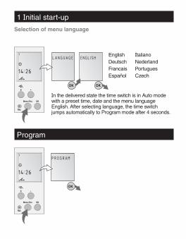
ENGLISHLANGUAGE EnglishDeutschFrancaisEspañol
ItalianoNederlandPortuguesCzech
In the delivered state the time switch is in Auto mode with a preset time, date and the menu language English. After selecting language, the time switch jumps automatically to Program mode after 4 seconds.
OK OK
Res
Menu/Esc OK
+
Res
Menu/Esc OK
+
1 Initial start-up
Selection of menu language
-
-

Program
New weekly program
The time switch has 50 memory spaces (25 ON, 25 OFF).
Example ON command at 3 pm. OFF command at 6 pm.
• Select NEW program and confirm with OK.
• Select WEEKLY program and confirm with OK.
• The free memory spaces are briefly displayed.
• Select day block or individual day (block formation as desired) and confirm with OK.
• Enter hour for ON command (+/-) and confirm with OK.
• Enter minute for ON command (+/-) and confirm with OK.
• Enter hour for OFF command (+/-) and confirm with OK.
• Enter minute for OFF command (+/-) and confirm with OK.
• Program is saved.
• Program jumps to selection WEEKLY. Now additional programs can be created.
OFF DAY OFF HOUR
15:00
OFF MIN
18:00
OK OK
SAVED
01:02
WEEKLY
Esc
ON DAY ON HOUR
00:00
ON MIN
15:00
OK OK
OK
OK
NEW WEEKLY
OK
FREE
50
OK OK
+/- +/- +/-
+/- +/- +/-

NEW HOLIDAY
New holidays program
OK
The HOLIDAY program is run every year unless changes are programmed in.
FREE
50
TO DAY
08:01
TO MON
07:26
FROM DAY
07:01
FROM MON
01:01
OK OK
ON DAY ON HOUR
00:00
OK
OK
OFF DAY
HOLIDAYSAVED
03:04
OFF HOUR
15:00
OFF MIN
18:00
ON MIN
15:00
Esc
OK OK OK
OK OKOK
OK OK
+/-
+/- +/- +/- +/-
+/- +/- +/- +/-+/-
+/- +/-

EDIT
Program
View, edit program
• The program steps can be scrolled through with “+/-”.
• The respective program can be edited by pressing OK.
• The procedure is the same as when creating a new program.
When deleting individual programs, the corresponding program steps are deleted e.g. P01 ON and P02 OFF.
SELECT
ALL
PO1
15:00
OFF MIN
19:00
PO2
18:00
PO2
19:00
OFF HOUR
18:00
PO1
15:00
OFF DAY
CONFIRMDELETE
DELETE
OK OK OK
OK
OK OK OK
OK
Esc
OK
CONFIRM
Delete individual programs
Delete all programs
OK OK
+/-
+/-
+/- +/- +/-
+/-
+/-
+/-
+/-

MONTH DATE
Set AM/PM (12-hour-) or 24-hour display
Set date and time
The date and time are preset at the factory.
PROGRAM DATETIME YEAR
2013
HOUR
00:00
MINUTE
21:00
24H
21:57
12H 24H
21:57
PROGRAM
07010101
AM PM
09:57
OK OK Esc
OKOK OK OK
OK OK+/-+/-
+/- +/- +/- +/-
+/- +/-

Switchover for summer/winter time
The following settings are possible:
AUTO Factory presetting of the published calendar dates. This is automatically recalculated for each year.
NO No switchover
NODAYLIGHTPROGRAM
OK
AUTODAYLIGHTPROGRAM
OK
SUMMER
03:25
WINTER
10:28
OK
OKOK OK
+/-+/-
+/- +/-

Calibrate Programming the start date of the summer time and winter time must be entered for this purpose. The factory presetting is overwritten. The programmed summer/winter time is automatically recalculated for each year. The changeover takes place on the same specified day of the week in the same week of each month. Also ideal for daylight savings periods.
Example 10/03 start summer time 03/31 start winter time
Attention! During the Summer/Winter switchover, alterations to time settings cannot occur.
CALIBRATDAYLIGHTPROGRAM
SU MONTH
03:25
SU DAY
03:21
OK
OK
OK
WI MONTH
10:28
OK
WI DAY
10:31
SUMMER
10:03
WINTER
03:31
OK
OK
OK
+/- +/-
+/- +/-
+/-+/-

Info
Press 1 x = FIX ON = continuous ON
Press 2 x = FIX OFF = continuous OFF
Press 3 x = return to Auto mode
FIX ON: FIX
FIX OFF: FIX
AUTO: (no display) programmed switching times
Operating mode
Technical SpecificationsDimensions H x W x D 45mm x 17.5mm x 60mmWeight g (approx.) 90Supply voltage See imprint on devicePower consumption 5 VASwitching capacity- Ohmic load (VDE, IEC)- Inductive load cos ϕ 0.6- Incandescent lamp load
16A 250V a.c.8A 250V a.c.1,000W
Switching output potential-freeSwitch contacts 1 changeover contactAmbient temperature -13°F to 131°F (-25°C to +55°C)Protection class IIAccuracy typ. ±2.5 s/day at +68°F (20°C)Reserve power 3 years from factory at 68°F (20°C)Shortest switching time 1 min.Memory spaces 50Block formation of day of the week Fixed/free selectionSwitching status display YesSealable Yes
Res
Menu/Esc OK
+ -