digisafe data diode model 328x security target v1
TRANSCRIPT

DigiSAFE Data Diode Model 328X
Security Target v1.0C
The information contained herein is the property of ST Electronics (Info-Security) Pte Ltd and
may not be copied, used or disclosed in whole or in part to any third party except with written
approval of ST Electronics (Info-Security) Pte Ltd or, if it has been authorised under a contract.
Date of Issue :
7/7/2018

DigiSAFE Data Diode Security Target i
DigiSAFE Data Diode Model 328X
Security Target
Contents
Preliminary Pages Page
Contents ...................................................................................................................................... i
List of Illustrations ................................................................................................................... iii
Chapter 1 – ST Introduction ................................................................................................ 1-1
1.1 ST Reference .................................................................................................... 1-1
1.2 TOE Reference................................................................................................. 1-1
1.3 TOE Overview ................................................................................................. 1-1
1.3.1 TOE Type ............................................................................................... 1-3
1.4 TOE Description .............................................................................................. 1-4
1.4.1 Physical Scope ........................................................................................ 1-4
1.4.2 Logical Scope of the TOE ...................................................................... 1-5
Chapter 2 – Conformance Claims ....................................................................................... 2-1
2.1 Conformance Claims ....................................................................................... 2-1
2.2 Conformance Rationale ................................................................................... 2-1
Chapter 3 – Security Problem Definition ........................................................................... 3-1
3.1 Threats.............................................................................................................. 3-1
3.2 Organizational Security Policies ...................................................................... 3-1
3.3 Assumptions ..................................................................................................... 3-1
Chapter 4 Security Objectives ............................................................................................. 4-1
4.1 Security Objectives for the TOE ...................................................................... 4-1
4.2 Security Objectives for the Operational Environment ..................................... 4-1
4.3 Security Objectives Rationale .......................................................................... 4-1
4.3.1 T. RCVDATALEAK .............................................................................. 4-2
4.3.2 A.PHYSICAL ......................................................................................... 4-2
4.3.3 A.USER .................................................................................................. 4-2
4.3.4 A.NETWORK ........................................................................................ 4-2
Chapter 5 Security Requirement ......................................................................................... 5-1

DigiSAFE Data Diode Security Target ii
5.1 Security Functional Requirements ................................................................... 5-1
5.1.1 Complete Information Flow Control (FDP_IFC.2) ................................ 5-1
5.1.2 Simple Security Attributes (FDP_IFF.1) ................................................ 5-1
5.1.3 Extended Components Definition .......................................................... 5-2
5.1.4 Security Requirement Rationale ............................................................. 5-2
5.2 Security Assurance Requirements ................................................................... 5-2
5.2.1 Rationale for Security Assurance Requirements .................................... 5-3
5.3 Security Requirement Dependency Table ....................................................... 5-3
5.4 TOE Summary Specification ........................................................................... 5-4

DigiSAFE Data Diode Security Target iii
List of Illustrations
Figure/Table Page
Table 1: Differences between TOE models ................................................................................. 1-3
Table 2 Tracing of security objectives to threats ......................................................................... 4-2
Table 3 Tracing of SFRs to Security Objectives ......................................................................... 5-2
Table 4 Security Assurance Requirement ................................................................................... 5-3
Table 5 Security Requirement Dependency Table ...................................................................... 5-4
Figure 1: TOE network configuration ......................................................................................... 1-1
Figure 2: TOE Block Diagram .................................................................................................... 1-2
Figure 3: TOE Data Flow ............................................................................................................ 1-6

Data Diode Security Target 1-1
Chapter 1 – ST Introduction
1.1 ST Reference
Title: DigiSAFE Data Diode model 328X Security Target
ST Version: 1.0C
ST Date: 7 Jul 2018
Author: Wu YongCong
1.2 TOE Reference
The TOE is uniquely identified as DigiSAFE Data Diode model 3282 version 2.2, model 3283
version 2.2, and model 3284 version 2.2.
Version number is based on the following format: Version <X>.<Y>
<X> represents the OS version running on the TOE
<Y> represents the software application version running on the TOE.
This TOE consists of 3 different hardware model. They are using the same OS and software.
1.3 TOE Overview
The Target of Evaluation (TOE) is a network gateway that ensures physical layer one-way data
transmission through the TOE.
The TOE is used to connect two independent networks together, denoted as the Sending Network
and Receiving Network. Sending Network connects to TOE via InterfaceLAN (Sender) interface
while Receiving Network connects to TOE via the InterfaceLAN (Receiver) interface. Figure 1
illustrates the network configuration which is also the evaluated TOE configuration.
Figure 1: TOE network configuration
The TOE ensures data can only flow from the Sending Network to the Receiving Network but
not in the reverse direction. The TOE block diagram is illustrated in Figure 2.

Data Diode Security Target 1-2
Figure 2: TOE Block Diagram
The TOE consists of two subsystems i.e. Sender Motherboard and Receiver Motherboard. These
two subsystems are physically separated from each other and are powered by independent power
supplies. The one-way data transmission property is achieved by the pair of customized SFP+
(see Figure 2) that are implemented on the Sender Motherboard and Receiver Motherboard
respectively. The SFP+ (Sender) on the Sender Motherboard consists of only an optical
transmitter and does not have any external interface to receive optical signals while the SFP+
(Receiver) on the Reciever Motherboard consists of only an optical sensor and does not have
optical transmitter; data can only be optically transmitted from SFP+ (Sender) to the SFP+
(Receiver) by virtue of the physical implementation.
Do note that the Port Management and File System modules in both Sender Motherboard and
Receiver Motherboard are SFR-non-interfering modules though they are considered part of the
TOE.
The physical layer one-way data transmission property of the TOE can address two security
problems:
It prevents information leak from Receiving Network to Sending Network.
It prevents the integrity of the data residing in the Sending Network from being
compromised by processes running in the Receiving Network.
The TOE consists of three model i.e. 3282, 3283 and 3284 that implements the same design and
one-way data transmission property as illustrated in Figure 2. The differences between the
models are further described in Table 1 below.
Model
Number
Picture of TOE Description
3282
Consists of one physical unit
The pair of customized SFP+ are
contained within the TOE
Non-TOE external interfaces
Sender Motherboard

Data Diode Security Target 1-3
1 x SFP port
Receiver Motherboard
1 x SFP port
3283
Consists of one physical unit
The pair of customized SFP+ are
exposed external interfaces
Non-TOE external interfaces
Sender Motherboard
1 x VGA ports
2 x USB ports
2 x RJ45 ports
Receiver Motherboard
1 x VGA ports
2 x USB ports
2 x RJ45 ports
3284
Consists of two physical unit.
Each unit contains the Sender
Motherboard and Receiver
Motherboard respectively
The pair of customized SFP+ are
exposed as external interfaces.
Non-TOE external interfaces
Sender Motherboard
1 x Console port
1 x USB
8 x Switch ports
Receiver Motherboard
1 x Console port
1x USB
8 x Switch ports
Table 1: Differences between TOE models
1.3.1 TOE Type
The TOE is physical layer unidirectional network gateway.

Data Diode Security Target 1-4
1.4 TOE Description
1.4.1 Physical Scope
1.4.1.1 TOE Hardware, and Software
Hardware
As illustrated in Figure 2, the TOE consists of two subsystems i.e. Sender Motherboard and
Receiver Motherboard. These two motherboards are physically separate from each other and are
connected to each other only via the pair of customised SFP+. The following provides a brief
description of the motherboards and customized SFP+.
Sender Motherboard;
This motherboard connects to Sending Network. It only connects to Receiver
Motherboard via the pair of customized SFP+.
Receiver Motherboard;
This motherboard will be connected to Receiving Network. It only connect to Sender
motherboard via the pair of customized SFP+.
SFP+ (Sender)
This is a module that is part of the Sender Motherboard. It consists of an optical
transmitter but does not contain any external interface to receive optical signals; it is
unable to receive optical signals from external.
SFP+ (Reciever)
This is a module that is part of the Receiver Motherboard. It only consists of an optical
sensor but not an optical transmitter; it is unable to transmit optical signals.
Power Supply (Sender) and Power Supply (Receiver)
Both module are independent power supplies that supply power to the respective Sender
Motheboard and Recevier Motherboard.
Software
Both the Sender Motherboard and Receiver Motherboard operates on Linux operating system
(OS). The following describes the software modules runs on the respective Sender Motherboard
and Receiver Motherboard.
Sender Motherboard o Sender Service
Receives data from Sending Network via standard networking protocol,
such as TCP, UDP, SYSLOG.
o Data Diode Client
Converts the standard protocol to the proprietary protocol
Sends the data to SFP+ (Sender) module.
o Port Management
Provides the Management Portal interface for users to configure the
expected networking protocol on the InterfaceLAN (Sender).
Data Diode Security Target 1-5
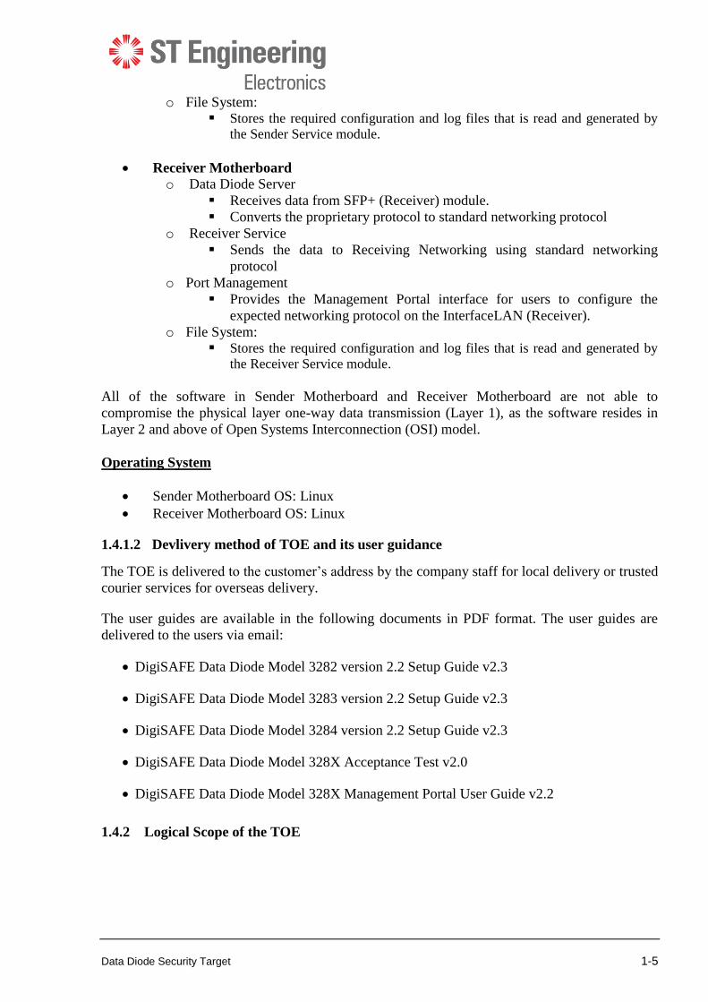
o File System: Stores the required configuration and log files that is read and generated by
the Sender Service module.
Receiver Motherboard o Data Diode Server
Receives data from SFP+ (Receiver) module.
Converts the proprietary protocol to standard networking protocol
o Receiver Service
Sends the data to Receiving Networking using standard networking
protocol
o Port Management
Provides the Management Portal interface for users to configure the
expected networking protocol on the InterfaceLAN (Receiver).
o File System: Stores the required configuration and log files that is read and generated by
the Receiver Service module.
All of the software in Sender Motherboard and Receiver Motherboard are not able to
compromise the physical layer one-way data transmission (Layer 1), as the software resides in
Layer 2 and above of Open Systems Interconnection (OSI) model.
Operating System
Sender Motherboard OS: Linux
Receiver Motherboard OS: Linux
1.4.1.2 Devlivery method of TOE and its user guidance
The TOE is delivered to the customer’s address by the company staff for local delivery or trusted
courier services for overseas delivery.
The user guides are available in the following documents in PDF format. The user guides are
delivered to the users via email:
DigiSAFE Data Diode Model 3282 version 2.2 Setup Guide v2.3
DigiSAFE Data Diode Model 3283 version 2.2 Setup Guide v2.3
DigiSAFE Data Diode Model 3284 version 2.2 Setup Guide v2.3
DigiSAFE Data Diode Model 328X Acceptance Test v2.0
DigiSAFE Data Diode Model 328X Management Portal User Guide v2.2
1.4.2 Logical Scope of the TOE
Data Diode Security Target 1-6
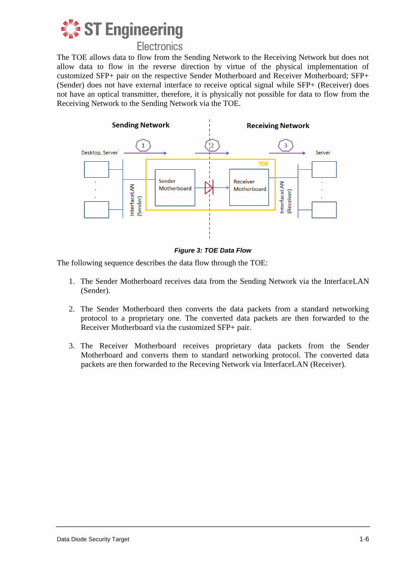
The TOE allows data to flow from the Sending Network to the Receiving Network but does not
allow data to flow in the reverse direction by virtue of the physical implementation of
customized SFP+ pair on the respective Sender Motherboard and Receiver Motherboard; SFP+
(Sender) does not have external interface to receive optical signal while SFP+ (Receiver) does
not have an optical transmitter, therefore, it is physically not possible for data to flow from the
Receiving Network to the Sending Network via the TOE.
Figure 3: TOE Data Flow
The following sequence describes the data flow through the TOE:
1. The Sender Motherboard receives data from the Sending Network via the InterfaceLAN
(Sender).
2. The Sender Motherboard then converts the data packets from a standard networking
protocol to a proprietary one. The converted data packets are then forwarded to the
Receiver Motherboard via the customized SFP+ pair.
3. The Receiver Motherboard receives proprietary data packets from the Sender
Motherboard and converts them to standard networking protocol. The converted data
packets are then forwarded to the Receving Network via InterfaceLAN (Receiver).

Data Diode Security Target 2-1
Chapter 2 – Conformance Claims
2.1 Conformance Claims
The TOE and ST are compliant with the Common Criteria (CC) Version 3.1, Revision 5, dated:
April 2017. The TOE and ST are CC Part 2 conformant and CC Part 3 conformant.
The ST is package conformant to the CC EAL2 assurance package.
2.2 Conformance Rationale
None.

Data Diode Security Target 3-1
Chapter 3 – Security Problem Definition
This TOE addresses the data leakage from Receiving Network to Sending Network.
3.1 Threats
This section describes the threats that are addressed by the TOE:
T.RCVDATALEAK: A user or process on the Receiving Network that accidentally or
deliberately breaches the confidentiality of data by transmitting data through TOE to the Sending
Network.
3.2 Organizational Security Policies
There are no Organizational Security Policies with which the TOE must comply.
3.3 Assumptions
The assumptions made about the TOE’s intended environment are:
A.PHYSICAL: The TOE shall be installed and operated in an environment which prevents
unauthorized physical access.
A.USER: The users are trusted; the users shall not maliciously compromise the security
functionality of the TOE. The users are well-trained; the user shall comply to the operating
procedures stipulated in the user guidance.
A.NETWORK: The information flow between Sending Network and Receiving Network must
pass through the TOE and there will be no other network connection between Sending Network
and Receiving Network.

Data Diode Security Target 4-1
Chapter 4 Security Objectives
4.1 Security Objectives for the TOE
O.ONEWAY: The TOE shall allow the data to flow from the Sending Network to the Receiving
Network but not in the reverse direction i.e. Receiving Network to the Sending Network.
4.2 Security Objectives for the Operational Environment
The following security objectives are required to assist the TOE in correctly providing its one-
way data transmission security function. These objectves are satisfied through application of
procedural or administrative measures.
OE.PHYSICAL: The TOE shall be installed and operated in a physically secure environment
which prevents unauthorized physical access.
OE.USER: The users are trusted; the users shall not maliciously compromise the security
functionality of the TOE. The users are well-trained; the user shall comply to the operating
procedures stipulated in the user guidance.
OE.NETWORK: The information flow between Sending Network and Receiving Network shall
pass through the TOE and there shall not be any other network connectivity between Sending
Network and Receiving Network.
Application Notes: It is recommended to use independent power supplies and network
infrastructure for the Sending Network and Receiving Network
4.3 Security Objectives Rationale
Table 2 maps security objectives to threats and assumptions described in Chapter 3. The table
illustrates that each threat is countered by at least one security objective, that each assumption is
upheld by at least one security objective, and that each objective counters at least one threat or
upholds at least one assumption.
This is then followed by explanatory text providing justification for each defined threat that if all
security objectives that trace back to the threat are achieved, the threat is removed, sufficiently
diminished, or that the effects of the threat are sufficiently mitigated. In addition, each defined
assumption is shown to be upheld if all security objectives for the operational environment that
trace back to the assumption are achieved.
Threats and
Assumptions
Security objectives
T.RCVDATALEAK
A.PHYSICAL
A.USER
A.NETWORK
O. ONEWAY √
OE.PHYSICAL √ √
OE.USER √ √
OE.NETWORK √ √

Data Diode Security Target 4-2
Table 2 Tracing of security objectives to threats
4.3.1 T. RCVDATALEAK
T.RCVDATALEAK: A user or process on the Receiving Network that accidentally or
deliberately breaches the confidentiality of data by transmitting data through TOE to the Sending
Network.
O.ONEWAY ensures that data is only allowed to flow from the Sending Network to the
Receiving Network but not in the reverse direction
OE.PHYSICAL ensures that the TOE is deployed in a physically secure environment i.e. only
authorized users are permitted physical access to the TOE. This prevents the implementation and
the configuration of the TOE from being tampered, thus bypassing or modifying the one-way
data transmission SFP
OE.USER ensures that users are trusted; users will not maliciously bypass or tamper the security
functionality of the TOE. It also ensures that the user are well-trained; users will not
unknowingly misconfigure the TOE which may lead to compromising the TOE security
functionality.
OE.NETWORK ensure that all network connections between the Sending Network and
Receiving Network passes through the TOE so that the one-way data transmission SFP is
preserved.
4.3.2 A.PHYSICAL
A.PHYSICAL: The TOE will be installed and operated in environment which prevents
unauthorized physical access.
OE.PHYSICAL directly upholds A.PHYSICAL.
4.3.3 A.USER
A.USER: The users are trusted; the users shall not maliciously compromise the security
functionality of the TOE. The user is well-trained; the user shall comply to the operating
procedures stipulated in the user guidance
OE.USER directly upholds A.USER.
4.3.4 A.NETWORK
A.NETWORK: The information flow between Sending Network and Receiving Network must
pass through the TOE and there will be no other network connection between Sending Network
and Receiving Network.
OE.NETWORK directly upholds A.NETWORK
Data Diode Security Target 5-1
Chapter 5 Security Requirement
5.1 Security Functional Requirements
The TOE uses two subjects: Sending Network and Receiving Network. These subjects are
connected to the TOE via InterfaceLAN (Sender) and InterfaceLAN (Receiver) respectively.
These subjects have no attributes.
This statement of SFRs does not define other subjects, objects, operations, security attributes or
external entities.
5.1.1 Complete Information Flow Control (FDP_IFC.2)
FDP_IFC.2 Complete information flow control
Hierarchical to: FDP_IFC.1 Subset information flow control
Dependencies: FDP_IFF.1 Simple security attributes
FDP_IFC.2.1 The TSF shall enforce the one-way data transmission in physical layer SFP on
any information from Sending Network to Receiving Network through the TOE and all
operations that cause that information to flow to and from subjects covered by the SFP.
FDP_IFC.2.2 The TSF shall ensure that all operations that cause any information in the TOE to
flow to and from any subject in the TOE are covered by an information flow control SFP.
5.1.2 Simple Security Attributes (FDP_IFF.1)
FDP_IFF.1 Simple security attributes
Hierarchical to: No other components.
Dependencies: FDP_IFC.1 Subset information flow control
FMT_MSA.3 Static attribute initialisation1
FDP_IFF.1.1 The TSF shall enforce the one-way data transmission in physical layer SFP
based on the following types of subject and information security attributes:
Subject: Sending Network , Receiving Network.
Information security attribute: Subject Identity2
FDP-IFF.1.2 The TSF shall permit an information flow between a controlled subject and
controlled information via a controlled operation if the following rules hold:
1 FMT_MSA.3 is not applicable as there is no security attributes to initalise 2 The subject identity is defined as the Sending Network and Receiving Network
Data Diode Security Target 5-2
a) The TSF shall allow the data from Sending Network to flow to the Receiving
Network.
b) The TSF shall deny data from the Receiving Network to flow to Sending Network.
FDP_IFF.1.3 The TSF shall enforce the None
FDP_IFF.1.4 The TSF shall explicitly authorise an information flow based on the following
rules: None.
FDP_IFF.1.5 The TSF shall explicitly deny an information flow based on the following rules:
None
5.1.3 Extended Components Definition
There are no extended components defined in this ST.
5.1.4 Security Requirement Rationale
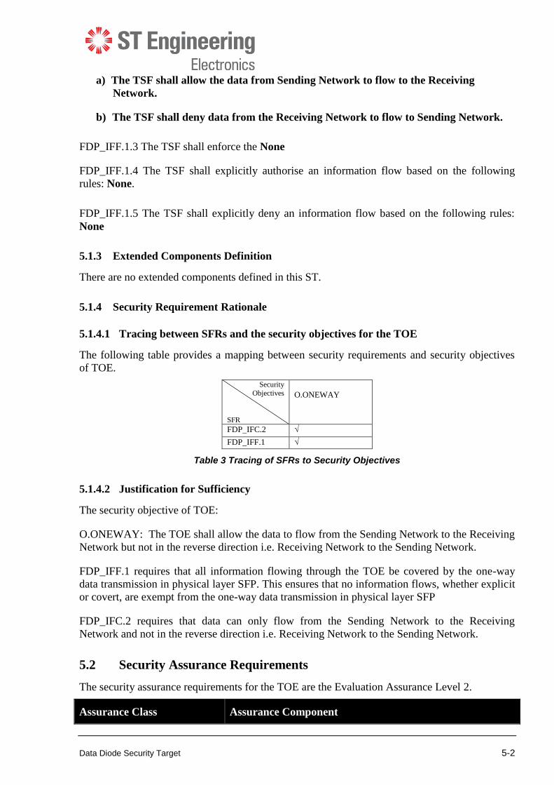
5.1.4.1 Tracing between SFRs and the security objectives for the TOE
The following table provides a mapping between security requirements and security objectives
of TOE.
Security
Objectives
SFR
O.ONEWAY
FDP_IFC.2 √
FDP_IFF.1 √
Table 3 Tracing of SFRs to Security Objectives
5.1.4.2 Justification for Sufficiency
The security objective of TOE:
O.ONEWAY: The TOE shall allow the data to flow from the Sending Network to the Receiving
Network but not in the reverse direction i.e. Receiving Network to the Sending Network.
FDP_IFF.1 requires that all information flowing through the TOE be covered by the one-way
data transmission in physical layer SFP. This ensures that no information flows, whether explicit
or covert, are exempt from the one-way data transmission in physical layer SFP
FDP_IFC.2 requires that data can only flow from the Sending Network to the Receiving
Network and not in the reverse direction i.e. Receiving Network to the Sending Network.
5.2 Security Assurance Requirements
The security assurance requirements for the TOE are the Evaluation Assurance Level 2.
Assurance Class Assurance Component

Data Diode Security Target 5-3
ADV: Development ADV_ARC.1 Security architecture description
ADV_FSP.2 Security-enforcing functional specification
ADV_TDS.1 Basic design
AGD: Guidance documents AGD_OPE.1 Operational user guidance
AGD_PRE.1 Preparative procedures
ALC: Life-cycle support ALC_CMC.2 Use of a CM system
ALC_CMS.2 Parts of the TOE CM coverage
ALC_DEL.1 Delivery procedures
ASE: Security target
evaluation
ASE_CCL.1 Conformance claims
ASE_ECD.1 Extended components definition
ASE_INT.1 ST introduction
ASE_OBJ.2 Security objectives
ASE_REQ.2 Derived security requirements
ASE_SPD.1 Security problem definition
ASE_TSS.1 TOE summary specification
ATE: Tests ATE_COV.1 Analysis of coverage
ATE_FUN.1 Functional testing
ATE_IND.2 Independent testing – sample
AVA: Vulnerability
assessment
AVA_VAN.2 Vulnerability analysis
Table 4 Security Assurance Requirement
5.2.1 Rationale for Security Assurance Requirements
The evaluation assurance package selected for the evaluation of the TOE is EAL2 assurance
package. EAL2 assurance package was chosen to provide resistance against Basic attack
potential that is consistent with commercial products for applications in the government. The
chosen assurance level is appropriate with the threats defined for the environment (physical
protection by the environment, limited interface and access to the TOE).
5.3 Security Requirement Dependency Table
Table 5 depicts the satisfaction of all security requirement dependencies. For each security
requirement included in the ST, the CC dependencies are identified in the column “CC
dependency”, and the satisfied dependencies are identified in the “ST dependency” column.

Data Diode Security Target 5-4
ST SFR ST Dependency CC Dependency Justification
FDP_IFC.2 FDP_IFF.1 FDP_IFF.1
FDP_IFF.1 FDP_IFC.2 FDP_IFC.1
FMT_MSA.3
FMT_MSA.3 is not
applicable because there is
no security attributes to
initialize.
Table 5 Security Requirement Dependency Table
5.4 TOE Summary Specification
The TOE addresses two security functional requirements: FDP_IFC.2 and FDP_IFF.1. They
work together to satisfy the security objective for TOE. The following provides a description of
the general technical mechanisms that the TOE uses to satisfy each SFR defined. It includes the
description of security functionality given in each SFR by reference and provides a high-level
view of their implementation in the TOE
FDP_IFC.2 : The TOE consists of two subsystems i.e. the Sender Motherboard and Receiver
Motherboard. Both the Sender Motherboard and Receiver Motherboard are entirely independent,
each with its own independent power and network interfaces, each enclosed in enclosure that
does not admit electrical or optical signals via any other than the described interfaces. Based on
the user guidance (stated in Chapter 1), the Sender Motherboard is only connected to the Sending
Network and is not connected to the Receiving Network. Conversely, the Receiver Motherboard
is connected only to the Receiving Network.
The Sender Motherboard and Receiver Motherboard are connected by only a single fiber-optic
cable. This fiber-optic cable is connected to each of the Sender Motherboard and Receiver
Motherboard via their respective customised SFP+ i.e. SFP+ (Sender) and SFP+ (Receiver). This
ensures that all data flowing through the TOE must flow through the fiber-optic cable and are
thereby covered by the one-way data transmission SFP.
FDP_IFF.1:The SFP+ (Sender) module converts incoming electrical signals into optical signals
while SFP+ (Receiver) module converts incoming optical signals into electrical signals. The
SFP+ (Sender) module contains an optical transmitter and not an optical sensor that can receive
optical signals externally. Conversely, the SFP+ (Receiver) module contains only an optical
sensor and not an optical transmitter. Hence, SFP+ (Sender) and SFP+ (Receiver) together
physically only allow data to flow from the Sending Network to Receiving Network but not in
the reverse direction.
References
1. Common Criteria for Information Technology Security Evaluation, Part 1: Introduction
and general model, April 2017, Version 3.1 Revision 5
2. Common Criteria for Information Technology Security Evaluation, Part 2: Security
functional components, April 2017, Version 3.1 Revision 5
3. Common Criteria for Information Technology Security Evaluation, Part 3: Security
assurance components, April 2017, Version 3.1 Revision 5
4. Common Criteria for Information Technology Security Evaluation, Evaluation
methodology, April 2017, Verson 3.1 Revision 5.