digipulse dual wire feeder - esab - f15-999/digipulse... · wire feeder bombardier ... aws c5.5 -...
TRANSCRIPT
INSTRUCTIONS for F-15-496-AMay, 1999
Be sure this information reaches the operator.You can get extra copies through your supplier.
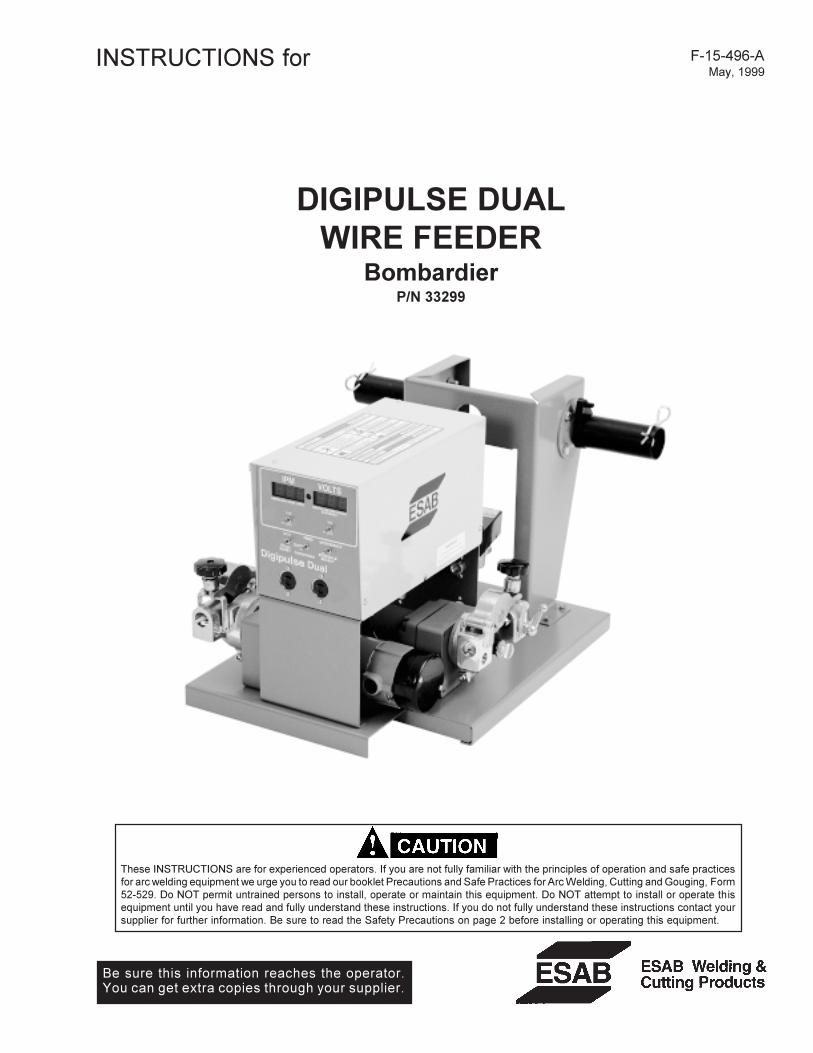
These INSTRUCTIONS are for experienced operators. If you are not fully familiar with the principles of operation and safe practicesfor arc welding equipment we urge you to read our booklet Precautions and Safe Practices for Arc Welding, Cutting and Gouging, Form52-529. Do NOT permit untrained persons to install, operate or maintain this equipment. Do NOT attempt to install or operate thisequipment until you have read and fully understand these instructions. If you do not fully understand these instructions contact yoursupplier for further information. Be sure to read the Safety Precautions on page 2 before installing or operating this equipment.
DIGIPULSE DUALWIRE FEEDER
BombardierP/N 33299

2
USER RESPONSIBILITY
This equipment will perform in conformity with the description thereof contained in this manual and accompanying labelsand/or inserts when installed, operated, maintained and repaired in accordance with the instructions provided. Thisequipment must be checked periodically. Malfunctioning or poorly maintained equipment should not be used. Partsthat are broken, missing, worn, distorted or contaminated should be replaced immediately. Should such repair orreplacement become necessary, the manufacturer recommends that a telephone or written request for service advicebe made to the Authorized Distributor from whom purchased.
This equipment or any of its parts should not be altered without the prior written approval of the manufacturer. The userof this equipment shall have the sole responsibility for any malfunction which results from improper use, faultymaintenance, damage, improper repair or alteration by anyone other than the manufacturer or a service facilitydesignated by the manufacturer.
TABLE OF CONTENTS
SECTION TITLE PAGEPARAGRAPH
SAFETY PRECAUTIONS .......................................................................................................................... 3
SECTION 1 DESCRIPTION ................................................................................................. 7
SECTION 2 INSTALLATION ................................................................................................ 12
SECTION 3 OPERATION ..................................................................................................... 16
SECTION 4 MAINTENANCE................................................................................................ 19
SECTION 5 REPLACEMENT PARTS .................................................................................. 22

3
WARNING: These Safety Precautions are foryour protection. They summarize precaution-ary information from the references listed inAdditional Safety Information section. Before
performing any installation or operating procedures, besure to read and follow the safety precautions listed belowas well as all other manuals, material safety data sheets,labels, etc. Failure to observe Safety Precautions can resultin injury or death.
PROTECT YOURSELF AND OTHERS --Some welding, cutting, and gougingprocesses are noisy and require earprotection. The arc, like the sun, emitsultraviolet (UV) and other radiation and
can injure skin and eyes. Hot metal can cause burns.Training in the proper use of the processes and equip-ment is essential to prevent accidents. Therefore:
1. Always wear safety glasses with side shields in any workarea, even if welding helmets, face shields, and gogglesare also required.
2. Use a face shield fitted with the correct filter and coverplates to protect your eyes, face, neck, and ears fromsparks and rays of the arc when operating or observingoperations. Warn bystanders not to watch the arc andnot to expose themselves to the rays of the electric-arcor hot metal.
3. Wear flameproof gauntlet type gloves, heavy long-sleeveshirt, cuffless trousers, high-topped shoes, and a weld-ing helmet or cap for hair protection, to protect againstarc rays and hot sparks or hot metal. A flameproof apronmay also be desirable as protection against radiatedheat and sparks.
4. Hot sparks or metal can lodge in rolled up sleeves,trouser cuffs, or pockets. Sleeves and collars should bekept buttoned, and open pockets eliminated from thefront of clothing
5. Protect other personnel from arc rays and hot sparkswith a suitable non-flammable partition or curtains.
6. Use goggles over safety glasses when chipping slag orgrinding. Chipped slag may be hot and can fly far.Bystanders should also wear goggles over safety glasses.
FIRES AND EXPLOSIONS -- Heat fromflames and arcs can start fires. Hot slagor sparks can also cause fires and ex-plosions. Therefore:
1. Remove all combustible materials well away from thework area or cover the materials with a protective non-flammable covering. Combustible materials include wood,cloth, sawdust, liquid and gas fuels, solvents, paints andcoatings, paper, etc.
2. Hot sparks or hot metal can fall through cracks orcrevices in floors or wall openings and cause a hiddensmoldering fire or fires on the floor below. Make certainthat such openings are protected from hot sparks andmetal.“
3. Do not weld, cut or perform other hot work until theworkpiece has been completely cleaned so that thereare no substances on the workpiece which might pro-duce flammable or toxic vapors. Do not do hot work onclosed containers. They may explode.
4. Have fire extinguishing equipment handy for instant use,such as a garden hose, water pail, sand bucket, orportable fire extinguisher. Be sure you are trained in itsuse.
SAFETY PRECAUTIONS
10/98
5. Do not use equipment beyond its ratings. For example,overloaded welding cable can overheat and create a firehazard.
6. After completing operations, inspect the work area tomake certain there are no hot sparks or hot metal whichcould cause a later fire. Use fire watchers when neces-sary.
7. For additional information, refer to NFPA Standard 51B,"Fire Prevention in Use of Cutting and Welding Pro-cesses", available from the National Fire Protection Asso-ciation, Batterymarch Park, Quincy, MA 02269.
ELECTRICAL SHOCK -- Contact with liveelectrical parts and ground can causesevere injury or death. DO NOT use ACwelding current in damp areas, if move-ment is confined, or if there is danger offalling.
1. Be sure the power source frame (chassis) is connectedto the ground system of the input power.
2. Connect the workpiece to a good electrical ground.3. Connect the work cable to the workpiece. A poor or
missing connection can expose you or others to a fatalshock.
4. Use well-maintained equipment. Replace worn or dam-aged cables.
5. Keep everything dry, including clothing, work area,cables, torch/electrode holder, and power source.
6. Make sure that all parts of your body are insulated fromwork and from ground.
7. Do not stand directly on metal or the earth while workingin tight quarters or a damp area; stand on dry boards oran insulating platform and wear rubber-soled shoes.
8. Put on dry, hole-free gloves before turning on the power.9. Turn off the power before removing your gloves.
10. Refer to ANSI/ASC Standard Z49.1 (listed on next page)for specific grounding recommendations. Do not mis-take the work lead for a ground cable.
ELECTRIC AND MAGNETIC FIELDS —May be dangerous. Electric current flow-ing through any conductor causes lo-calized Electric and Magnetic Fields(EMF). Welding and cutting current cre-ates EMF around welding cables andwelding machines. Therefore:
1. Welders having pacemakers should consult their physi-cian before welding. EMF may interfere with some pace-makers.
2. Exposure to EMF may have other health effects which areunknown.
3. Welders should use the following procedures to minimizeexposure to EMF:A. Route the electrode and work cables together. Secure
them with tape when possible.B. Never coil the torch or work cable around your body.C. Do not place your body between the torch and work
cables. Route cables on the same side of your body.D. Connect the work cable to the workpiece as close as
possible to the area being welded.E. Keep welding power source and cables as far away
from your body as possible.
4
FUMES AND GASES -- Fumes andgases, can cause discomfort or harm,particularly in confined spaces. Donot breathe fumes and gases. Shield-ing gases can cause asphyxiation.Therefore:
1. Always provide adequate ventilation in the work area bynatural or mechanical means. Do not weld, cut, or gougeon materials such as galvanized steel, stainless steel,copper, zinc, lead, beryllium, or cadmium unless posi-tive mechanical ventilation is provided. Do not breathefumes from these materials.
2. Do not operate near degreasing and spraying opera-tions. The heat or arc rays can react with chlorinatedhydrocarbon vapors to form phosgene, a highly toxicgas, and other irritant gases.
3. If you develop momentary eye, nose, or throat irritationwhile operating, this is an indication that ventilation is notadequate. Stop work and take necessary steps to im-prove ventilation in the work area. Do not continue tooperate if physical discomfort persists.
4. Refer to ANSI/ASC Standard Z49.1 (see listing below)for specific ventilation recommendations.
5. WARNING: This product, when used for welding orcutting, produces fumes or gases whichcontain chemicals known to the State ofCalifornia to cause birth defects and, insome cases, cancer. (California Health &Safety Code §25249.5 et seq.)
CYLINDER HANDLING -- Cylinders, ifmishandled, can rupture and violentlyrelease gas. Sudden rupture of cylin-der, valve, or relief device can injure orkill. Therefore:
1. Use the proper gas for the process and use the properpressure reducing regulator designed to operate fromthe compressed gas cylinder. Do not use adaptors.Maintain hoses and fittings in good condition. Followmanufacturer's operating instructions for mounting regu-lator to a compressed gas cylinder.
2. Always secure cylinders in an upright position by chainor strap to suitable hand trucks, undercarriages, benches,walls, post, or racks. Never secure cylinders to worktables or fixtures where they may become part of anelectrical circuit.
3. When not in use, keep cylinder valves closed. Havevalve protection cap in place if regulator is not con-nected. Secure and move cylinders by using suitablehand trucks. Avoid rough handling of cylinders.
4. Locate cylinders away from heat, sparks, and flames.Never strike an arc on a cylinder.
5. For additional information, refer to CGA Standard P-1,"Precautions for Safe Handling of Compressed Gases inCylinders", which is available from Compressed GasAssociation, 1235 Jefferson Davis Highway, Arlington,VA 22202.
EQUIPMENT MAINTENANCE -- Faulty orimproperly maintained equipment cancause injury or death. Therefore:
1. Always have qualified personnel perform the installa-tion, troubleshooting, and maintenance work. Do notperform any electrical work unless you are qualified toperform such work.
2. Before performing any maintenance work inside a powersource, disconnect the power source from the incomingelectrical power.
3. Maintain cables, grounding wire, connections, powercord, and power supply in safe working order. Do notoperate any equipment in faulty condition.
4. Do not abuse any equipment or accessories. Keepequipment away from heat sources such as furnaces,wet conditions such as water puddles, oil or grease,corrosive atmospheres and inclement weather.
5. Keep all safety devices and cabinet covers in positionand in good repair.
6. Use equipment only for its intended purpose. Do notmodify it in any manner.
ADDITIONAL SAFETY INFORMATION -- Formore information on safe practices for elec-tric arc welding and cutting equipment, askyour supplier for a copy of "Precautions andSafe Practices for Arc Welding, Cutting andGouging", Form 52-529.
The following publications, which are available from theAmerican Welding Society, 550 N.W. LeJuene Road, Mi-ami, FL 33126, are recommended to you:1. ANSI/ASC Z49.1 - "Safety in Welding and Cutting"2. AWS C5.1 - "Recommended Practices for Plasma Arc
Welding"3. AWS C5.2 - "Recommended Practices for Plasma Arc
Cutting"4. AWS C5.3 - "Recommended Practices for Air Carbon
Arc Gouging and Cutting"5. AWS C5.5 - "Recommended Practices for Gas Tungsten
Arc Welding“6. AWS C5.6 - "Recommended Practices for Gas Metal Arc
Welding"“7. AWS SP - "Safe Practices" - Reprint, Welding Hand-
book.8. ANSI/AWS F4.1, "Recommended Safe Practices for
Welding and Cutting of Containers That Have HeldHazardous Substances."
MEANING OF SYMBOLS - As used through-out this manual: Means Attention! Be Alert!Your safety is involved.
Means immediate hazards which, ifnot avoided, will result in immediate,serious personal injury or loss of life.
Means potential hazards which couldresult in personal injury or loss of life.
Means hazards which could result inminor personal injury.
SP98-10

5
a. Éloigner suffisamment tous les matériaux combustiblesdu secteur où l’on exécute des soudures ou descoupes à l’arc, à moins de les recouvrir complètementd’une bâche non-inflammable. Ce type de matériauxcomprend notamment le bois, les vêtements, la sciure,l’essence, le kérosène, les peintures, les solvants, legaz naturel, l’acétylène, le propane et autres sub-stances combustibles semblables.
b. Les étincelles ou les projections de métal incandescentpeuvent tomber dans des fissures du plancher ou dansdes ouvertures des murs et y déclencher une ignitionlente cachée. Veiller à protéger ces ouvertures desétincelles et des projections de métal.
c. N’exécutez pas de soudures, de coupes, d’opérationsde gougeage ou autres travaux à chaud à la surfacede barils, bidons, réservoirs ou autres contenantsusagés, avant de les avoir nettoyés de toute trace desubstance susceptible de produire des vapeursinflammables ou toxiques.
d. En vue d’assurer la prévention des incendies, ilconvient de disposer d’un matériel d’extinction prêt àservir immédiatement, tel qu’un tuyau d’arrosage, unseau à eau, un seau de sable ou un extincteur portatif.
e. Une fois le travail à l’arc terminé, inspectez le secteurde façon à vous assurer qu’aucune étincelle ou projec-tion de métal incandescent ne risque de provoquerultérieurement un feu.
3. CHOC ÉLECTRIQUE-- Le gougeage à l’arc et à l’arcau plasma exige l’emploi de tensions à viderelativement importantes; or, celles-ci risquent decauser des dommages corporels graves et mêmemortels en cas d’utilisation inadéquate. La gravité duchoc électrique reçu dépend du chemin suivi par lecourant à travers le corps humain et de son intensité.
a. Ne laissez jamais de surfaces métalliques sous tensionvenir au contact direct de la peau ou de vêtementshumides. Veillez à porter des gants bien secs.
b. Si vous devez effectuer un travail sur une surfacemétallique ou dans un secteur humide, veillez à assu-rer votre isolation corporelle en portant des gants secset des chaussures à semelles de caoutchouc et envous tenant sur une planche ou une plate-formesèche.
c. Mettez toujours à la terre le poste de soudage/coupageen le reliant par un câble à une bonne prise de terre.
d. N’utilisez jamais de câbles usés ou endommagés. Nesurchargez jamais le câble. Utilisez toujours unéquipement correctement entretenu.
e. Mettez l’équipement hors tension lorsqu’il n’est pas enservice. une mise à la masse accidentelle peut en effetprovoquer une surchauffe de l’équipement et un dan-ger d’incendie. Ne pas enrouler ou passer le câbleautour d’une partie quelconque du corps.
f. Vérifiez si le câble de masse est bien relié à la pièce enun point aussi proche que possible de la zone detravail. Le branchement des câbles de masse àl’ossature du bâtiment ou en un point éloigné de lazone de travail augmente en effet le risque depassage d’un courant de sortie par des chaînes de
PRÉCAUTIONS DE SÉCURITÉAVERTISSEMENT: Ces règles de sécurité ont pour objetd’ assurer votre protection. Veillez à lire et à observer lesprécautions énoncées ci-dessous avant de monter l’équipement ou de commercer à l’utiliser. Tout défautd’observation de ces précautions risque d’entraîner desblessures graves ou mortelles.1. PROTECTION INDIVIDUELLE-- Les brûlures de la
peau et des yeux dues au rayonnement de l’arcélectrique ou du métal incandescent, lors du soudageau plasma ou à l’électrode ou lors du gougeage àl’arc, peuvent s’avérer plus graves que celles résultantd’une exposition prolongée au soleil. Aussi convient-ild’observer les précautions suivantes:
a. Portez un écran facial adéquat muni des plaquesprotectrices et des verres filtrants appropriés afin devous protéger les yeux, le visage, le cou et les oreillesdes étincelles et du rayonnement de l’arc électriquelorsque vous effectuez des soudures ou des coupesou lorsque vous en observez l’exécution.
AVERTISSEZ les personnes se trouvant à proximitéde façon à ce qu’elles ne regardent pas l’arc et à cequ’elles ne s’exposent pas à son rayonnement, ni àcelui du métal incandescent.
b. Portez des gants ignifugés à crispins, une tuniqueépaisse à manches longues, des pantalons sansrebord, des chaussures à embout d’acier et uncasque de soudage ou une calotte de protection, afind’éviter d’exposer la peau au rayonnement de l’arcélectrique ou du métal incandescent. ll est égalementsouhaitable d’utiliser un tablier ininflammable defaçon à se protéger des étincelles et du rayonnementthermique.
c. Les étincelles ou les projections de métal incandescentrisquent de se loger dans des manches retroussées,des bords relevés de pantalons ou dans des poches.Aussi convient-il de garder boutonnés le col et lesmanches et de porter des vêtements sans poches àl’avant.
d. Protégez des étincelles et du rayonnement de l’arcélectrique les autres personnes travaillant à proximitéà l’aide d’un écran ininflammable adéquat.
e. Ne jamais omettre de porter des lunettes de sécuritélorsque vous vous trouvez dans un secteur où l’oneffectue des opérations de soudage ou de coupage àl’arc. Utilisez des lunettes de sécurité à écrans ouverres latéraux pour piquer ou meûler le laitier. Lespiquetures incandescentes de laitier peuvent êtreprojetées à des distances considérables. Lespersonnes se trouvant à proximité doivent égalementporter des lunettes de protection.
f. Le gougeage à l’arc et le soudage à l’arc au plasmaproduisent un niveau de bruit extrêmement élevé (de100 à 114 dB) et exigent par conséquent l’emploi dedispositifs appropriés de protection auditive.
2. PRÉVENTION DES INCENDES-- Les projections delaitier incandescent ou d’étincelles peuventprovoquer de graves incendies au contact dematériaux combustibles solides, liquides ou gazeux.Aussi faut-il observer les précautions suivantes:
9/97

6
levage, des câbles de grue ou divers cheminsélectriques.
g. Empêchez l’apparition de toute humidité, notammentsur vos vêtements, à la surface de l’emplacement detravail, des câbles, du porte-électrode et du poste desoudage/coupage. Réparez immédiatement toutefuite d’eau.
4. VENTILATION-- La respiration prolongée des fuméesrésultant des opérations de soudage/coupage, àl’intérieur, d’un local clos, peut provoquer des mal-aises et des dommages corporels. Aussi convient-ild’observer les précautions suivantes:
a. Assurez en permanence une aération adéquate del’emplacement de travail en maintenant une ventila-tion naturelle ou à l’aide de moyens mécaniques.N’effectuez jamais de travaux de soudage ou decoupage sur des matériaux de zinc, de plomb, deberyllium ou de cadmium en l’absence de moyensmécaniques de ventilation capables d’empêcherl’inhalation des fumées dégagées par ces matériaux.
b. N’effectuez jamais de travaux de soudage ou decoupage à proximité de vapeurs d’hydrocarburechloré résultant d’opérations voisines de dégraissageou de pulvérisation. La chaleur dégagée ou lerayonnement de l’arc peut déclencher la formation dephosgène -- gaz particulièrement toxique -- et d’autresgaz irritants, à partir des vapeurs de solvant.
c. Une irritation momentanée des yeux, du nez ou de lagorge constatée au cours de l’utilisation del’équipement dénote un défaut de ventilation. Arrêtez-vous de travailler afin de prendre les mesures néces-saires à l’amélioration de la ventilation. Ne poursuivezpas l’opération entreprise si le malaise persiste.
d. Certaines commandes comportent des canalisationsoù circule de l’hydrogène. L’armoire de commande estmunie d’un ventilateur destiné à empêcher la forma-tion de poches d’hydrogène, lesquelles présentent undanger d’explosion; ce ventilateur ne fonctionne que sil’interrupteur correspondant du panneau avant setrouve placé en position ON (Marche). Veillez àmanœuvrer cette commande en vérifiant si lecouvercle est bien en place, de façon à assurerl’efficacité de la ventilation ainsi réalisée. Ne jamaisdébrancher le ventilateur.
e. Les fumées produites par l’opération de soudage oude coupage peuvent s’avérer toxiques. Aussi est-ilnécessaire de disposer en permanence d’un dispositifadéquat de ventilation de type aspirant, afin d’élimi-ner du voisinage de l’opérateur tout dégagement defumée visible.
f. Consultez les recommandations particulières enmatière de ventilation indiquées à l’alinéa 6 de lanorme Z49.1 de l’AWS.
5. ENTRETIEN DE L’ÉQUIPEMENT-- Un équipemententretenu de façon défectueuse ou inadéquate risquenon seulement de réaliser un travail de mauvaise
qualité mais, chose plus grave encore, d’entraîner desdommages corporels graves, voire mortels endéclenchant des incendies ou des chocs électriques.Observez par conséquent les précautions suivantes:
a. Efforcez-vous de toujours confier à un personnel qua-lifié l’installation, le dépannage et l’entretien du postede soudage et de coupage. N’effectuez aucuneréparation électrique sur l’équipement à moins d’êtrequa-lifié à cet effet.
b. Ne procédez jamais à une tâche d’entretienquelconque à l’intérieur du poste de soudage/coupage, avant d’avoir débranché l’alimentationélectrique.
c. Maintenez en bon état de fonctionnement les câbles,le câble de masse, les branchements, le cordond’alimentation et le poste de soudage/coupage.N’utilisez jamais le poste ou l’équipement s’il présenteune défectuosité quelconque.
d. Prenez soin du poste de soudage et de coupage et deséquipements accessoires. Gardez-les à l’écart dessources de charleur, notamment des fours, del’humidité, des flaques d’eau maintenez-les à l’abri destraces d’huile ou de graisse, des atmosphères corro-sives et des intempéries.
e. Laissez en place tous les dispositifs de sécurité et tousles panneaux de l’armoire de commande en veillant àles garder en bon état.
f. Utilisez le poste de soudage/coupage conformément àson usage prévu et n’effectuez aucune modification.
6. INFORMATIONS COMPLÉMENTAIRES RELATIVES ÀLA SÉCURITÉ--
Pour obtenir des informations complémentaires sur lesrègles de sécurité à observer pour le montage etl’utilisation d’équipements de soudage et de coupageélectriques et sur les méthodes de travailrecommandées, demandez un exemplaire du livret N°52529 “Precautions and Safe Practices for Arc Weld-ing, Cutting and Gouging” publié par ESAB. Nousconseillons également de consulter les publicationssui-vantes, tenues à votre disposition par l’AmericanWelding Society, 550 N.W. LeJuene Road, Miami, FL32126:
a. “Safety in Welding and Cutting” AWS Z49.1b. “Recommended Safe Practices for Gas-Shielded Arc
Welding “AWS A6. 1.c. “Safe Practices for Welding and Cutting Containers
That Have Held Combustibles” AWS-A6.0.d. “Recommended Safe Practices for Plasma Arc Cutting”
AWS-A6. 3.e. “Recommended Safe Practices for Plasma Arc Weld-
ing” AWS-C5. 1.f. “Recommended Safe Practices for Air Carbon Arc
Gouging and Cutting” AWS-C5. 3.g. “Code For Safety in Welding and Cutting”
CSA-Standard W117. 2.
9/97

7
LOCATION FOR OPT.WATER CONNECTIONS
POWER CABLEADAPTOR BLOCK
POWER ON-OFF SW.
J1 CONTROL RECPT.
RESET CIRCUIT BREAKER
RUN-SET KEY SW.
LEFT TORCH GAS SOLCONNECTION
RIGHT TORCH GASSOL CONNECTION
Fig. 1 - Digipulse Dual Feeder
INTRODUCTION
This Digipulse Dual wire feeder is designed as a �dual�torch welder with each torch capable of furnishing eightcompletely different sets of welding parameters�inother words, sixteen (16) completely different weldingschedules can be preset to meet the requirements ofhigh production shops. The standard Dual control fea-tures include presettable wire feed speed (ipm), volt-age, pre and postflow gas shielding, cold wire inching,gas purging, adaptive or manual burnback, spot weld-ing timer and crater fill functions.
SECTION I DESCRIPTION
SPINDLE ASSY.
RIGHT DIGITAL READOUT (VOLT)
RIGHT INC-DEC TOGGLESPOT/BACK-SELECT SWITCH
TORCH ACCY. RIGHTSUPPORT ASSY.& EH-10 MOTOR-GEAR-TACH UNIT
RIGHT TORCH RECPT.
LEFT TORCH ACCY.SUPPORT ASSY.& EH-10 MOTORGEAR TACH UNIT
LEFT TORCH RECEPT.
INCH/GAS PURGERESET SELECTOR
LEFT INC-DEC TOGGLE
LEFT DIGITAL READOUT (IPM)
CRATER SELECTOR SW.
SPECIFICATIONS
Input Power Required ....................... 115 volts 50/60 Hz single phase WireFeed Speed Range ................................... 20-999 in./min. (.5-26.4 m/min.)Wire Sizes Accommodated:Hard/Soft � ............................................. .023 thru 1/8-in. (.6 thru 3.2 mm)Flux Cored � ......................................... .035 thru 1/8-in. (0.9 thru 3.2 mm)Length ................................................................................ 24-in. (610 mm)Width ............................................................................ 22-1/2-in. (572 mm)Height ................................................................................. 15-in. (381 mm)Weight (less wire) .................................................................. 80-lbs. (36 kg)

8
A. STANDARD FEATURES/BENEFITSn microprocessor accuracy � the microprocessor, the
controlling "brain" of the Digipulse Dual, operatesexclusively on drift free digital logic. The digital logicdelivers extraordinarily precise computer-accurateweld parameter control and weld consistency.
n microprocessor flexibility � the Digipulse incorpo-rates electronically reprogrammable modules; by sim-ply reprogramming this small plug-in module manyexisting functions may be extended or new featuresmaybe added.
n microprocessor reliability � ESAB�s Digipulse DualWire Feeders have proven to be rugged and reliablein test after test for absolute minimum downtime.
n presettable wire feed speed (Ipm) and voltage (volts)� provides ability to easily and accurately preset theexact welding parameters desired before the weldingsequence begins.
n patented microprocessor controlled closed loop sys-tems � provides most accurate means of maintainingwire feed speed (amperage) and welding voltage; themicroprocessor compensates for deviations in ambi-ent temperature primary voltage fluctuation andchanges in arc dynamics or wire feed force conditions,to assure that preset parameters are maintained.
n sure start interlock � to assure trouble free starts theDigipulse Dual has an interlock circuit which will notallow wire feed to initiate when the torch trigger Ispulled unless the power supply contactor is closedand voltage is present; the cold wire INCH, however,will be operative at all times.
n individual digital LED meters provide large 1/2-in.readout of voltage and wire feed speed � continuousdisplay of preset and then actual welding voltage andwire feed speed for accurate observation.
n automatic "shut down" � assures welding is done atthe preset parameters; unit automatically shuts down,if for any reason either the volts or ipm cannot bemaintained for a preprogrammed time period; simul-taneously, cause is indicated by flashing digital dis-play.
n toggle switch adjustment of weld parameters by fineincrements or rapid coarse adjustment � allowsquick, easy, and accurate adjustments of weldingparameters.
n gas pre and postflow and cold wire inch capability�gas pre and postflow provides independent adjust-ment in tenths of a second for highest weld quality andeconomy; cold wire inch speed can be independentlyadjusted from welding wire feed speed to reducedowntime.
n eight schedule capability per torch�enables operatorto have two different sets of weld parameters (for eachtorch) at his fingertips. The microprocessor allows theoperator to change schedules with a simple �click-click� squeeze of the torch trigger switch to be used.
n automatic adaptive anti-stick or manual burnbacktime feature�a patented adaptive anti-stick circuitautomatically adjusts the same amount of wireburnback regardless of wire size, speed or voltage; or,you can manually preset a �BurnbackTime� to specifi-cally suit a specialized application; the manual burnbackfunction (programmed up to 30 cycles in the VOLTSwindow) allows you to override the automatic adaptiveanti-stick by setting a specific burnback time.
n spot weld timer�because the spot weld timer isadjustable up to 999 cycles (16.5 sec.) in the IPMwindow, it is more than a conventional �spot� feature;it is also a weld timer extending its use for �Increment��or �Stitch� welding.
n the Crater Fill feature allows the operator to preset aspecial welding wire feed speed (IPM), arc length(VOLTS) and time (TIMES) to control the shape andsize of the weld crater upon termination of the weld-ing process.
n circuit protection�resettable circuit breaker for inputpower minimizes downtime and maintenance.
n EH-10A permanent magnet motors�provide the high-est torque, fastest response, and best efficiency ofany mig p.m. motor on the market.
n patented closed loop �J� governor/optical tachom-eter�provides most accurate means of maintainingwire feed speed and voltage, regardless of any volt-age drop or drift.
SECTION I DESCRIPTION

9
I. DESCRIPTION
The Digipulse Dual torch welder is a microprocessorcontrolled digital wire feeder designed for mig short arc/spray and pulse arc welding applications. Its electronicbrain � the microprocessor � not only controls, it alsoremembers and automatically coordinates the programsequencing (that �you� preset) which results in the mostaccurate wire feed speed and voltage control possible.
By virtue of its microprocessor controlled wire speed andarc voltage design, the Digipulse Dual allows the cus-tomer to preset 8 welding parameters (for each torch),and be assured that each setting will be precisely heldregardless of changes in line voltage, arc or load condi-tions.
Two digital readout windows continuously display (1/2-in. high) the preset welding parameters (speed andvoltage). After the arc is struck, they automatically dis-play the actual wire speed and arc voltage conditions forthe selected schedule. The read-outs can also provideselectable displays of other welding parameters such asinching speed, gas pre- and postflow times, spot time incycles, manual burnback time in cycles, schedule selec-tion, crater times and conditions.
The Dual Digipulse uses a pair of heavy duty EH-10Awire drive motors designed to feed hard or soft wires from.023-in. to 1/8-in. in diameter and flux-cored wires from.035-in to 1/8-in. in diameter. Rate of wire feed (20-999ipm) is precisely controlled by using a closed-loop �J�governor digital feedback circuit that employs an opticaltachometer to monitor the motor speed. Arc voltageregulation is also controlled by a closed-loop digitalfeedback circuit that monitors the arc voltage and auto-matically adjusts the power source output voltage tomaintain the preset voltage.
For identification and location of all functional controlsand connections refer to Figure 1. The front panelcontains the torch switch receptacles which use lowvoltage (5 v.d.c.) for operator safety. The rear panelcontains the on-off power switch, the run/set switch, a 7-ampere reset circuit breaker for overload protection, a19-pin receptacle (J1) provides 115vac, contactor con-trol, arc monitoring and control signals from the powersource.
All interconnecting cable, hose and auxiliary equipmentconnections are quickly detachable to provide easysetup and maximum portability of the wire feeder asshown in Figs. 2 & 3. A water kit with or without solenoidmay be purchased, as an optional accessory, for use withwater-cooled torch operation.
II. REQUIRED EQUIPMENT
A. CONSTANT VOLTAGE POWER SOURCEThe Digipulse Dual is specifically designed for use withconstant voltage (C.V.) power sources utilizing �elec-tronically controlled voltage regulation� such as:*SVI-450i, P/N 34055
* The power sources provides three (3) �Slope� outputs� Flat, Medium and Steep.
B. CABLE ASSEMBLIESA multi-conductor control cable assembly is required toconnect the Digipulse to a power source with electronicvoltage control (see Fig. 3).
115 Volt/Contactor/Remote Control J1 Cable, 19-con-ductor with Amphenol to Amphenol plugs; order one ofthe following:
6-foot. 19-cond., P/N 30686.30-foot, 19-cond., P/N 30780.60-foot, 19-cond., P/N 30781.
C. WELDING TORCHMig welding torches, with contact tip, wire conduit andoutlet guide for wire size/type to be employed, will berequired. Suitable air (MT-400) or water-cooled (MT-450W, ST-16) torches may be used with the Digipulse.
When using a water-cooled torch it will be necessary toconnect the torches water hose to either a continuouswater supply or to the wire feeder base by using anoptional water kit (with or without a solenoid valve, seeSection III-A and B).
D. GAS REGULATIONShielding gas regulator/flowmeter and fitted hose tobring gas from flowmeter to wire feeder. Such as:Regulator/Flowmeters:
R-5007 Argon/Helium/Nitrogen, P/N 998124.R-5008 C0
2, P/N 998125.
Gas Hoses:Standard Duty, P/N 40V77 (12-1/2-ft.) or P/N 34V38(25-ft.)Heavy Duty, P/N 19416 (12-1/2-ft.) uor P/N 19415(25-ft.).u
u Must be used for C02.
SECTION I DESCRIPTION
10
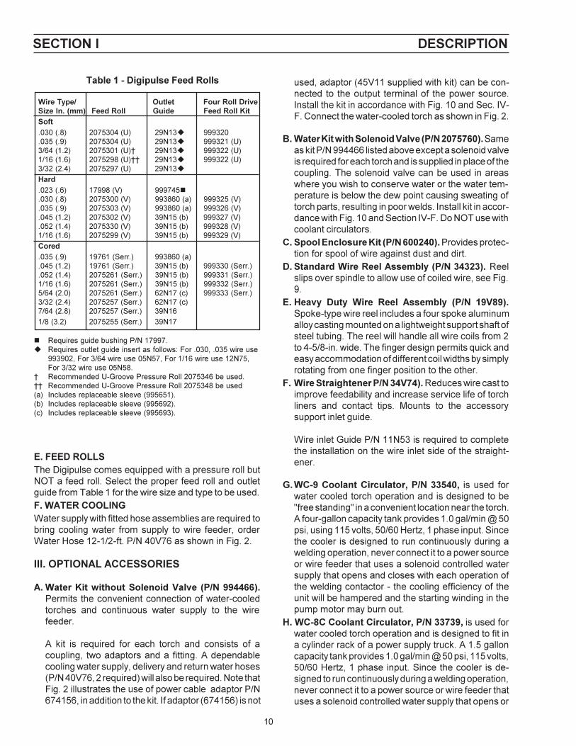
Table 1 - Digipulse Feed Rolls
Wire Type/ Outlet Four Roll DriveSize In. (mm) Feed Roll Guide Feed Roll KitSoft.030 (.8) 2075304 (U) 29N13u 999320.035 (.9) 2075304 (U) 29N13u 999321 (U)3/64 (1.2) 2075301 (U)� 29N13u 999322 (U)1/16 (1.6) 2075298 (U)�� 29N13u 999322 (U)3/32 (2.4) 2075297 (U) 29N13u
Hard.023 (.6) 17998 (V) 999745n.030 (.8) 2075300 (V) 993860 (a) 999325 (V).035 (.9) 2075303 (V) 993860 (a) 999326 (V).045 (1.2) 2075302 (V) 39N15 (b) 999327 (V).052 (1.4) 2075330 (V) 39N15 (b) 999328 (V)1/16 (1.6) 2075299 (V) 39N15 (b) 999329 (V)
Cored.035 (.9) 19761 (Serr.) 993860 (a).045 (1.2) 19761 (Serr.) 39N15 (b) 999330 (Serr.).052 (1.4) 2075261 (Serr.) 39N15 (b) 999331 (Serr.)1/16 (1.6) 2075261 (Serr.) 39N15 (b) 999332 (Serr.)5/64 (2.0) 2075261 (Serr.) 62N17 (c) 999333 (Serr.)3/32 (2.4) 2075257 (Serr.) 62N17 (c)7/64 (2.8) 2075257 (Serr.) 39N16
1/8 (3.2) 2075255 (Serr.) 39N17
n Requires guide bushing P/N 17997.u Requires outlet guide insert as follows: For .030, .035 wire use
993902, For 3/64 wire use 05N57, For 1/16 wire use 12N75,For 3/32 wire use 05N58.
� Recommended U-Groove Pressure Roll 2075346 be used.�� Recommended U-Groove Pressure Roll 2075348 be used(a) Includes replaceable sleeve (995651).(b) Includes replaceable sleeve (995692).(c) Includes replaceable sleeve (995693).
E. FEED ROLLSThe Digipulse comes equipped with a pressure roll butNOT a feed roll. Select the proper feed roll and outletguide from Table 1 for the wire size and type to be used.F. WATER COOLINGWater supply with fitted hose assemblies are required tobring cooling water from supply to wire feeder, orderWater Hose 12-1/2-ft. P/N 40V76 as shown in Fig. 2.
III. OPTIONAL ACCESSORIES
A. Water Kit without Solenoid Valve (P/N 994466).Permits the convenient connection of water-cooledtorches and continuous water supply to the wirefeeder.
A kit is required for each torch and consists of acoupling, two adaptors and a fitting. A dependablecooling water supply, delivery and return water hoses(P/N 40V76, 2 required) will also be required. Note thatFig. 2 illustrates the use of power cable adaptor P/N674156, in addition to the kit. If adaptor (674156) is not
used, adaptor (45V11 supplied with kit) can be con-nected to the output terminal of the power source.Install the kit in accordance with Fig. 10 and Sec. IV-F. Connect the water-cooled torch as shown in Fig. 2.
B. Water Kit with Solenoid Valve (P/N 2075760). Sameas kit P/N 994466 listed above except a solenoid valveis required for each torch and is supplied in place of thecoupling. The solenoid valve can be used in areaswhere you wish to conserve water or the water tem-perature is below the dew point causing sweating oftorch parts, resulting in poor welds. Install kit in accor-dance with Fig. 10 and Section IV-F. Do NOT use withcoolant circulators.
C. Spool Enclosure Kit (P/N 600240). Provides protec-tion for spool of wire against dust and dirt.
D. Standard Wire Reel Assembly (P/N 34323). Reelslips over spindle to allow use of coiled wire, see Fig.9.
E. Heavy Duty Wire Reel Assembly (P/N 19V89).Spoke-type wire reel includes a four spoke aluminumalloy casting mounted on a lightweight support shaft ofsteel tubing. The reel will handle all wire coils from 2to 4-5/8-in. wide. The finger design permits quick andeasy accommodation of different coil widths by simplyrotating from one finger position to the other.
F. Wire Straightener P/N 34V74). Reduces wire cast toimprove feedability and increase service life of torchliners and contact tips. Mounts to the accessorysupport inlet guide.
Wire inlet Guide P/N 11N53 is required to completethe installation on the wire inlet side of the straight-ener.
G. WC-9 Coolant Circulator, P/N 33540, is used forwater cooled torch operation and is designed to be"free standing" in a convenient location near the torch.A four-gallon capacity tank provides 1.0 gal/min @ 50psi, using 115 volts, 50/60 Hertz, 1 phase input. Sincethe cooler is designed to run continuously during awelding operation, never connect it to a power sourceor wire feeder that uses a solenoid controlled watersupply that opens and closes with each operation ofthe welding contactor - the cooling efficiency of theunit will be hampered and the starting winding in thepump motor may burn out.
H. WC-8C Coolant Circulator, P/N 33739, is used forwater cooled torch operation and is designed to fit ina cylinder rack of a power supply truck. A 1.5 galloncapacity tank provides 1.0 gal/min @ 50 psi, 115 volts,50/60 Hertz, 1 phase input. Since the cooler is de-signed to run continuously during a welding operation,never connect it to a power source or wire feeder thatuses a solenoid controlled water supply that opens or
SECTION I DESCRIPTION

11
Fig. 2 - Torch and Service Interconnection diagram
SECTION I DESCRIPTION
RIGHT TORCHMOTOR/ACC. SUPPORT
PLAN VIEW DUAL FDR.
GAS HOSE40V77 (12-1/2 FT.)34V38 (25 FT.)
LEFT TORCH(WATER COOLED)
TORCH SWITCHTORCH GAS HOSE
n TORCH WATER HOSE
TORCH POWER CABLE
TORCH CONDUIT
n ADAPTOR - 45V11
nWATER "DRAIN" HOSE - 40V76 (12-1/2 FT.)
nWATER KIT (BELOW)2075760
OR
nWATER KIT994466
GAS HOSE40V77 (12-1/2 FT.)34V38 (25 FT.)
REGULATOR/FLOWMETER nWATER "IN" HOSE - 40V76
(12 1/2 FT.)
REGULATOR/FLOWMETER
REF. CONTROL'S REARSUPPORT FRAME
GAS SOLENOIDS ABOVEOPT. WATER SOL. BELOW
TORCH CONDUIT
TORCH SWITCH
TORCH GAS HOSE
TORCH POWER CABLE
RIGHT TORCH(AIR COOLED)
FRONTVIEWCONTROL
n Parts required whenusing a Water Kit & Water
LEFT TORCHMOTOR/ACC. SUPPORT
closes with each operation of the welding contactor -the cooling efficiency of the unit will be hampered andthe starting winding in the pump motor may burn out.
I. Wire Feeder Turntable P/N 678940, allows rotationof wire feeder as operator changes work positions.This reduces strain and bending of torch cables.
J. Four Roll Drive Accessory Support Assembly, P/N 600216. This assembly (shown in booklet F-12-821) utilizes 4 feed rolls to provide positive nonslipwire feed. It is designed for feeding .030 thru 1/8-in.diameter wire. Feed rates for the 4-roll drive arevirtually the same as with the 2-roll drive. For feed roll/outlet guide accessories refer to Table 1.

12
IV. INSTALLATION
To avoid possible lethal shock make sure that allpower to the Digipulse is OFF before making anywelding/control cable and or accessory connec-tions on this unit. Do this by "locking-open" theinput line disconnect switch to the power source.
After checking to be sure you have all required compo-nents and accessories (see Section II), proceed asfollows (with reference to Figs. 2 & 3, InterconnectionDiagrams):
A. HOSE AND ELECTRICAL CONNECTIONSConnect shielding gas and water (if used) supply hosesas shown in Fig. 2. Connect the control cable assembly(J1) from the Digipulse�s rear panel to the power sourceas shown in Fig. 3.
B. TORCH CONNECTIONSAttach torch gas hose to gas connections. Plug in torchswitch cables and lock by twisting. After inserting conduitliner (if used) and attaching wire outlet guide of correctsize, connect wire feed conduit to welding head clampand lock in place. Attach water hose (if used) to wirefeeder. Connect torch power cables to power source, orto power cable adaptor block (with a second cable fromthat stud to the power source).
C. INSTALLING FEED ROLL1. Release the clapper on the accessory support assem-
bly (Figure 8) by disengaging the retainer from theclapper fork.
2. Remove thumbscrew, belleville washer, and flatwasher from the feed roll shaft.
3. Slip the feed roll on the shaft, engaging the key. Besure to observe this �THIS SIDE OUT� marking on thefeedroll.
4. Reassemble flatwasher, belleville washer, and thumbscrew, tightening screw sufficiently to eliminate all endplay from the feed roll.
D. INSTALLING SPOOL OF WIRECAUTION: Make sure safety glasses are worn when
clipping wire off at the spool or at the end ofthe torch - serious eye injury can result dueto the springiness of the wire which quicklyunravels, or a cut wire end which may shootacross the room.
1. Remove �hairpin� clip from spindle.
2. Position the spool of wire so that when it is placed onthe spindle, wire will be drawn to the feed roll from thebottom of the spool. The spool should be held so thatthe index hole on the back will engage the lug on thespindle.
3. Slide the spool onto the spindle until it engages the lug.Lock in place with the hairpin clip.
4. Loosen the brake screw in the center of the spindlehub, then tighten it just enough to prevent coasting ofthe spool when wire is drawn from it. Too muchpressure will load the wire feed motor unnecessarily.Too little pressure will permit the spool to over-run,causing the wire to kink and tangle.
5. Thread the wire on to the accessory support assemblyas described in Section E.
6. When wire coils are to be used instead of spools,mount wire reel on spindle as through it were a spool(see 1 and 3 above). Remove thumbnuts and coverplate from reel. Remove coil from its package, but donot remove its binding wires. Slide coil onto reel so thatwire will be drawn from bottom of coil (starting end fora coil is always the outer end). Replace reel coverplate and thumbnuts. Cut off coil tie wires and anykinked wire. Then adjust brakescrew and thread wireto torch as covered in 4 and 5 above.
E. ADJUSTING THE ACCESSORY SUPPORT ASSEM-BLY (See Fig. 8).
When a new wire size or type is to be used, set thepressure roll adjustment as follows:
1. Round off the free end of the welding wire with a file.2. Release the clapper and unscrew the pressure ad-
justing knob until the pressure spring is free.3. Thread the wire through the inlet and outlet guides of
the accessory support, and 3 or 4 inches into the torchconduit.
4. Engage the clapper making sure the wire is held in thefeed roll groove.
5. Tighten the pressure adjusting knob until the wire isfirmly against the feed roll - do not overtighten. Thespring pressure applied should be the minimum re-quired to provide positive, nonslip wire feed. Too littlepressure will result in wire slippage while excessivepressure will scar and deform the wire. Further adjust-ment can be made after the wire feed is put intooperation. Note that a light silver-colored spring(182W55) is installed on the accessory support foruse with soft and small diameter hard wire. For largediameter hard wire, replace this spring with a heavyblue- colored spring (182W54) supplied with the unit.
SECTION 2 INSTALLATION

13
A. CONTROL FUNCTIONSFor location of rear panel control features, refer to Fig. 4.
1. Power Switch. This two-position toggle switch turnspower �on� or �off� to the wire feeder control.
2. Run Set Key. This "key-operated� switch must be inthe SET position to preset, vary and weld-test thewelding parameters programmed into the control (e.g.:
F. WATER KITS (Optional see Fig. 10)Mount bulkhead adaptor (58V75) behind opening pro-vided in rear vertical support plate, below gas connec-tions, and secure with screws (No. 8 - 32 x 3/8-in.) andlockwashers provided. Attach coupling or solenoid valve(depending on the type of water kit) and adaptor (11N16)to the bulkhead adaptor. Mount torch cable adaptor(45V11) on welding power stud. Connect water drainhose to this adaptor, and water inlet hose to adaptor11N16. Wire the solenoid valve (if used) in parallel withthe gas solenoid valve (see wiring diagram).
V. ADJUSTMENTS
Do not allow metal-to-metal contact between thewire feeder chassis and a metal surface connectedin any way to a welding ground. With such contact,a poor welding ground connection may create adifference In potential that sends part of the weldcurrent through the safety ground wiring in thecontrol cable and wire feeder, resulting in burnout ofthat wiring and/or damage to wire feeder circuitry. Ifthe safety ground burns out, the operator may beexposed to 115V. shock hazard.
� ESAB will not honor the warranty on Digipulse that are used with non-ESAB manufacturedinterconnect cables and sustain damage that in ESAB�s opinion is caused by these cables.For a listing of the proper cables available refer to Section II-B.
* 4/0 welding cables (customer supplied) are set-up for DCRP (NEG. TO WORK) operation.
Fig. 3 - Welding and Control Interconnection Diagram
SECTION 2 INSTALLATION
Fig. 4 - Rear Panel Control
TYPICAL POWERSUPPLY HOOKUP
TO WORK*
RECPT.
4/0 WELDING CABLE*
POWER CABLEADAPTOR
J1 CABLE
J1

14
Sched. I, Sched. II for each torch, Spot). After thedesired results are achieved, the program(s) can be�locked-in� by turning the key to the RUN position. Theonly parameter which can be altered by the operatorin the RUN position is the cold wire INCH speed.
3. Reset Circuit Breaker. A seven (7) ampere circuitbreaker provides protection to the 115-volt controlcircuit and the wire feed motor. If an overload occurs,the breaker will trip and suspend all operation. Torestore service, depress the breaker button to resetthe circuit.
4. Digital Readout Windows. Two individual three-digitwindows are provided to display preset or actualwelding parameters as follows:a. IPM Digital Readout. This window is primarily
used to display wire feed speed in IPM from 20 to999 inch per minute in one inch increments. How-ever, with the appropriate function selector actu-ated, this window can also display the following:� shielding gas PREFLOW from .1 to 99.9 sec-
onds in one tenth of a second increments.� SPOT welding time for each Torch, from 1 to 999
cycles in 1 cycle increments.� cold wire INCH speed in IPM from 50 to 999
inches per minute in one inch increments.� Schedule select-Left Torch� Crater time - Left Torch
NOTE: With the power turned �on�, but not welding, theIPM window will �continuously� read Preset wirespeed. When the arc is struck, the IPM windowwill then continuously read Actual welding wirespeed.
b. Volts Digital Readout. This window is primarilyused to display arc voltage in VOLTS from 12 to 50vdc in one tenth volt increments. However, with theappropriate toggle selector actuated, this windowcan also display the following:� shielding gas POSTFLOW from .1 to 99.9 sec-
onds in one tenth of a second increments.� accumulative welding ARC HOUR usage record
in one tenth of an hour increments.� manual BURNBACK time. Manually adjustable
burnback time period which when preset willoverride the automatic adaptive anti-stick fea-ture. This time period will be set In one-cycle (60cycle = 1 sec.) Increments. When set to �zero�,the Automatic Anti-stick feature will be opera-tional.
� Schedule select - Right Torch� Crater time - Right Torch
NOTE: With the power turned �on�, but not welding, theVOLTS window will �continuously� read Presetvoltage. When the arc is struck, the VOLTS
window will then continuously read Actual weld-ing voltage.
5. LED Light. This LED lights to indicate that the torch onthe left side is in use.
NOTE: All of the following controls are spring-loaded,center-return toggle switches which must beoperated to actuate their indicated function(s).Item No. 6 describes the adjustment settingtoggle used to preset the program- functionselectors. Except as noted above and following,regulation for selected function(s) can only bemade if Item No. 2 is in the SET position.
SECTION 2 INSTALLATION
Fig. 4A - Front Panel Controls
6. Inc.-Dec. Toggle Switches. Two control toggles areprovided to preset the individual welding parametersrequired for the selected welding mode as follows:
a. �IPM � Increase/Decrease Control. This toggleswitch is primarily used to set and/or vary the wirefeed speed (IPM), along with its other functions;Preflow, Spot for both torches, Inch, Crater timeand Left Side schedule. With appropriate functionselector actuated, each parameter setting will bedisplayed in the digital window directly above thistoggle.
b. �VOLTS� Increase/Decrease Control. This toggleswitch is primarily used to set and/or vary the arcVolts, along with all its other functions: Postflow,Burnback, Right Side schedule and Crater time.With the appropriate function selector actuated,each parameter setting will be displayed in thedigital window directly above this toggle.
7. Inch-Gas Purge/Abort Reset Selector. This twoposition (momentary �on� contact) switch allows thefollowing operation.a. Inch Function. The INCH selection permits cold-
wire inching without energizing the welding circuitthrough the torch switch. The preset cold wiringinching speed (set in Item 9) can also be indepen-
4A
6A
7
5
4B
6B
8
9

15
programming is chosen by simply squeezingand releasing the torch switch lever for theparticular torch desired. The manual Burnbacktime(s) is adjustable in one cycle increments(60 cycles/sec.) and is programmed in theVOLTS window using its Inc/Dec toggle switch.When preset, the Burnback time will overridethe automatic adaptive anti-stick feature in ei-ther schedule for that particular torch. If auto-matic anti-stick operation is desired, theBurnback time must be keyed back to �zero�.
Schedule Select. When the switch is in theschedule select position, any schedule from 1through 8 can be selected for the torch in use.Schedules 1 - 4 are provided for pulse weldingand schedules 5 - 8 for short arc welding.
9. "Crater" Times/Conditions. This toggle switch al-lows the operator to preset a special welding wirefeed speed (IPM), arc length (VOLTS) and time(TIMES) to control the shape and size of the weldcrater .
Each weld schedule can be preset with a uniquecrater fill IPM, VOLTAGE and crater time.
B. GAS/WIRE ADJUSTMENTSThe following Digipulse control functions must be set tofeed wire through the torch conduit and to adjust theshielding gas flow rate.
1. Place Power switch (rear panel) to �on� position toenergize the control.
2. Place key-operated Lock-In Set switch (rear panel) inSet position.
3. With torch connections made as shown in Fig. 2, andwire engaged in accessory support (Sect. IV-E), feedwire through torch conduit and into torch as follows:a. Actuate and immediately release the torch switch
lever for the Left Torch/Motor. This action (thru thecontrol�s switching relay circuitry) sets-up the con-trol to receive the parameter programming for theLeft Torch.
b. Remove nozzle and contact tip from torch.c. Hold Inch-Purge toggle in INCH position (Sect. V-
A-8) until �cold� wire protrudes from the torch frontend.
d. Slide the contact tip over the end of the wire andsecure it to the torch. Replace the torch nozzle.
e. Reoperate Inch-Purge toggle in INCH position andcheck for wire feed slippage on the accessorysupport assembly. Tighten (or loosen) the pres-sure adjusting knob until the wire feeds smoothly.
f. Now, actuate and immediately release the torchswitch lever for the Right Torch/Motor. This action(thru the control�s switching relay circuitry) sets-upthe control to receive the parameter programmingfor the Right Torch, and you can repeat steps b-e.
dently changed by operating its associated Inc./Dec. toggle switch, and this setting (which is inde-pendent of �hot� wire feed) will appear in the IPMwindow.
b. The Gas PURGE (Abort Reset) position providesthe following when actuated:(1) During initial programming, it permits preset-
ting of gas PREFLOW and POSTFLOW �timerequirements� which are simultaneously dis-played in the IPM and VOLTS windows respec-tively.
(2) Prior to actual torch triggering, it permits youto actuate the gas solenoid and PURGE theshielding gas line of the torch. At the same time,it also lets you adjust the gas regulator withoutenergizing the welding circuit.
(3) After starting the welding sequence, if an�abort-shutdown� condition occurs (indicatedby a flashing digital display). The RESET posi-tion can be actuated and the control automati-cally �resets� for a new start.
8. Spot/Burnback. This two- position (momentary con-tacts) switch allows the following operations:
Spot Weld/Manual Burnback times. Actuat-ing this position allows you to preset either orboth of these features for either or both torches.
The SPOT time mode can be programmed intoeither schedule (I or II) for each torch � and thetorch selected for operation is chosen by simplysqueezing and releasing the torch switch leverfor the particular torch desired. These preset�timed-arc� periods (up to 999 cycles, in onecycle increments) are programmed in the IPMwindow using its Inc/Dec toggle switch. Whenthe Spotwelding feature has been preset intoone of the schedules for a particular torch,all �continuous" welding applications forthat torch are temporarily disabled. To re-sume normal program operation in Schedules Iand II for either or both torches, you must deac-tivate the Spotweld mode by keying its timingparameter back to �zero�.
When a spotweld time is programmed for atorch, the "click-click" torch switch feature forchanging schedules cannot be used as it was for�continuous-type� welding operations. To changeschedules for spotwelding, you must manuallyreposition the Schedule toggle switch selector tothe desired schedule for that torch�the torchswitch is only used to start the arc, and the spottime cuts it off (unless the torch switch is prema-turely released).
At the same time, you can also preset amanual BURNBACK time mode into any sched-ule for each torch�and the torch selected for
SECTION 2 INSTALLATION

16
4. With shielding gas cylinder and torch gas hose con-nection assembled as shown in Fig. 2, set gas flowrate as follows:a. Hold Inch-Purge toggle in PURGE position and
open the gas regulator-flowmeter control valve andset the shielding gas flow rate.
b. Continue to hold the Purge position for approx. 15seconds to insure adequate purging of each gashose and torch.
5. Place control�s Power switch to �off� position.
VI GENERAL
This dual pulse Mig welding system has beendesigned and manufactured to specifications providedby Bombardier, Inc.. The software is modified toprovide eight separate schedules for each torch. Thefirst four schedules (1-4) on each torch are dedicatedto pulse welding of stainless steel in the synergicmode. The second four schedules (5-8) are dedicatedto short or spray arc welding and have no synergicrelationships. This means that IPM and VOLTS areentered separately depending if a short arc or sprayarc weld condition is required. The following will detailthe set-up and operation of this unique weldingsystem.
Start UpAssembly of the power source, feeder andinterconnect cable is the same as specified in thegeneral operating instruction manuals provided withthe SVI-450i Power Source and Digipulse Dual wirefeeder. After power up of the SVI-450i (460 Vac) andthe feeder, the windows on the feeder will displayIPM=51 and VOLTS=45 for a brief period. Thisindicates that the stainless steel program (same as astandard Digipulse) is running and the synergic curveis for .045-inch (1.2 mm) diameter wire. Theseparameters CANNOT be changed. The windows willthen display the last welding parameters set by theoperator. Place the �Remote/Panel� switch on theSVI-450i power source in the �Remote� position andfollow the instructions below.
Selecting System Presets
System parameters are those that affect BOTHtorches and ALL schedules. These parameters arealways active and should be set first. They are:
Gas preflow presetGas postflow presetCold inch presetTrigger selection (dual schedule operation)Half speed run-in
Set the shield gas preflow parameters by holdingdown the �Purge� key and using the �Inc/Dec� keyunder the IPM window to set a preflow time in 1/10seconds. Repeat the above for postflow using the keybelow the VOLTS window.
The cold inching feature is a two speed design. Whenplacing the �Inch� key in the �up� position, the feedmotor will operate at 50 ipm for a period of 2-1/2seconds. This is for �bumping� the wire to adjust thewire stick-out from the contact tip. After 2-1/2seconds the wire feed speed will transfer to the coldinching speed shown in the IPM window. The wirefeed speed can be further adjusted using the �Inc/Dec�key under the IPM window. This function is designedfor wire threading.
The �Trigger Selection� option allows dual scheduleoperation. This means that two welding schedules areavailable to the operator on each torch. This option isdisabled when Rocker Switch #4 on Dip Switch #2 isin the �closed� position. Dip switch #2 is located onthe MPU board inside the feeder control box. Placethis switch in the �open� position for �Trigger� selection(dual schedule operation). Welding will always beginusing the current weld schedule selected. �Doubleclicking� the torch trigger switch changes the weldingparameters to the next highest schedule number. Seediagram below.
Example:
If pulse arc welding is being used in schedule #4,�double click� the torch trigger to switch to the short/spray arc parameters resident in schedule #5.�Double click� the torch trigger a second time causesthe weld parameters to switch back to the pulse weldparameters in schedule #4. Releasing the torchtrigger stops welding.
SECTION 3 OPERATING INSTRUCTIONS

17
The Trigger Selection function (dual scheduleoperation) is automatically disabled when a spot weldtime is preset or its crater conditions are set for theschedules in use on that torch. See �Torch ParameterPresets� below.
Half speed run-in is always �on� when using the pulsearc schedules (1 to 4). Half speed run-in will also be�on� in the short/spray arc schedules (5 to 8) when thearc voltage is 26 volts or higher. Below 26 volts willresult in full speed run-in of the welding wire. Thisoption is enabled when Rocker Switch #1 on DipSwitch #2 is in the �open� position. Dip switch #2 islocated on the MPU board inside the feeder controlbox . Place this switch in the �closed� position for fullspeed run-in for all welding schedules 1 to 8. Thisfunction is triggered off the high open circuit voltage(OCV) of the SVI-450i power source. Half speed run-in cannot be enabled using power sources having alow OCV.
Torch Parameter Presets
Each torch can have the following parameters orvariables preset:
Schedule number presetWire burnback presetSpot weld timeCrater timeCrater conditions
The software will automatically switch to the torchbeing used when the torch trigger is depressed. Eachtorch may have two welding schedules assigned at atime when using the Trigger Selection mode(described above). The right side torch (viewed fromthe front of the feeder) is the default torch setting.This means that when the feeder is first powered upthis torch and its parameters will be displayed. If a redlight between the IPM and VOLTS display windows isilluminated, the left side torch parameters are beingdisplayed.
Choose the schedule number (1- 8) for each torch bydepressing the �Schedule Selection� key and settingthe desired schedule number in IPM window for theleft torch and the VOLTS window for the right torch.
Preset the desired burnback by �depressing� the torchtrigger switch to be preset. This action displays thecurrent welding parameters for that torch. Hold�Burnback/Spot� key in the �up� position and set aburnback number in VOLTS window. Repeat thisprocedure for the other torch.
Attach the desired gas mixture to the appropriate torchfor the type of welding to be completed.
Some shielding gases will not pulse arc and short arcequally well. Therefore, the optimization of both pulsearc and short/spray arc parameters will be dependenton the shielding gas and its ability to support bothprocesses.
If spot welding is desired, �depress� the torch triggerswitch to be preset. This action displays the currentwelding parameters for that torch. Hold the�Burnback/Spot�� key in the �up� position and set aspot time in seconds in the IPM window. Repeat thisprocedure for the other torch if desired. Entering aspot weld time automatically disables the �TriggerSelection� mode and dual schedule operation is notpossible.
Weld Schedule Parameter Presets
Pulse Arc Welding
Schedules 1 through 4 are dedicated pulse arcwelding schedules for stainless steel using .045" (1.2mm) diameter wire. The synergic relationship is thesame on each torch and for each schedule. Whenentering a schedule number 1 to 4, the feeder controland power source is automatically set for pulsewelding with .045" stainless steel wire.
Note: The SVI-450i power source slope switch shouldbe set to the STEEP slope position. TheINDUCTANCE & VOLTAGE knob on the SVI-450i is deactivated.
The IPM window will display the wire feed speed ininches per minute and the VOLTS window will show anumber between 0 and 200 with 100 being the defaultvalue. These numbers relate to the synergicrelationship programmed into the software andcorrespond to a pulse frequency. The number 100 isthe nominal pulse frequency required for the wire feedspeed selected in the IPM window. This number willalso affect the arc length. If the welding arc length istoo long the number can be decreased which shortensthe arc length. If the welding arc is too short, increasethe number in the VOLTS window. Each count in thewindow changes the pulse frequency by one pulse persecond.
SECTION 3 OPERATING INSTRUCTIONS

18
Short/Spray Arc Welding
When setting a schedule number 5 to 8, the feedercontrol and power source is automatically set forshort/spray welding. The operator has full control overthe slope and inductance of the power source. TheIPM window will display the preset wire feed speed ininches per minute. The VOLTS window will displayarc voltage and can be adjusted to any arc voltageneeded for a good welding condition by using the �Inc/Dec� key under the VOLTS window. The feedercontrol will automatically adjust the power source tomaintain the arc voltage set in the VOLTS window.There is no synergic relationship present in the short/spray arc schedules.
Crater Fill
The Crater Fill feature allows the operator to preset aspecial welding wire feed speed (IPM), arc length(VOLTS) and time (TIMES) to control the shape and sizeof the weld crater upon termination of the welding pro-cess.
Each weld schedule can be preset with a unique craterfill IPM, VOLTAGE and crater time. The feeder thus of-fers 16 sets of crater conditions.
NoteWhen a crater TIME is programmed, the �double click�method of changing torch schedules by using the weld-ing torch trigger is automatically disabled for that torch.
Programming a Crater Condition
1. Momentarily depress the trigger of the torch to beprogrammed. Be sure the desired schedule num-ber is assigned to that torch. Schedules 1 - 4 arePulse arc welding schedules and schedules 5 - 8are Short Circuiting/Spray arc welding schedules.
2. Hold the Crater toggle switch in the TIMES position.The window corresponding to the torch being usedwill illuminate. Enter the desired crater time (in sec-onds) using the INC/DEC switch under the illumi-nated window. A zero (0) will disable the crater fillfeature.
3. Hold the Crater toggle switch in the CONDITIONSposition and enter the crater IPM and VOLTS set-tings desired using the INC/DEC toggle switchesbeneath their respective window.
4. During welding the crater fill schedule will be en-abled when the operator releases the torch trigger.The crater timer will start and the arc will extinguishautomatically when the preset crater time has timedout.
5. The preset crater time can be terminated also byreoperating the torch switch during the crater condi-tion.
6. For a legitimate crater condition, both crater speedand crater time needs to be set.
Arc Start (Servo) Settings - For short or spray arcwelding only, not applicable to pulse welding.
Each schedule on each torch can have its own startingcharacteristic for any given weld parameter. The arcstart level must be set during welding. Choosedesired schedule number and set a good weldingcondition. If the arc starting is less than desirable itcan be adjusted as follows:
Depress the �Purge� and �Schedule Select� keysimultaneously while making a weld (two manoperation). The VOLTS window will display a numberbetween 0 and 200 (95 is the typical setting). Usingthe �Inc/Dec� key below the VOLTS window, reducethe number shown to give a �hotter� arc start orincrease the number for a �colder� arc start. Yoursetting will be saved to that schedule and will berecalled when you select that schedule again.Changes in wire feed speed and/or voltage mightnecessitate readjusting the voltage servo to optimizestarting characteristics. Repeat this procedure forother welding schedules being used.
Note: The set number 80 - 95 will only effect thestarts, it will not change the preset arc voltage.
Motor Servo Setting
You can adjust the feed motor response by presettingthe motor speed servo. Release the pressure roll andpull the torch switch while depressing the �Purge� and�Schedule Select� key simultaneously. Change thenumber (110 is standard) in the IPM window using the�Inc/Dec� key to a lower value if a faster motoracceleration is needed or a higher number for aslower motor acceleration.
The motor response adjustment will be in effectfor ALL schedules and BOTH torches. The servonumber set in the IPM window can be set exactlyfor the schedule being used and wire feed speedpreset but switching to a different schedulehaving a different wire feed speed setting willcause the servo number in the IPM window to varyslightly. This is normal and should have littleaffect on welding performance.
SECTION 3 OPERATING INSTRUCTIONS

19
Vll. TROUBLESHOOTING
Listed below are a number of trouble symptomseach followed by the checks or action suggested todetermine the cause. Listing of checks and/or ac-tions is in �most probable� order but is not neces-sarily 100% exhaustive. Always follow this generalrule: Do not replace a printed circuit (PC) board untilyou have made all the preceding checks. Always putthe Power switch in off position before removing orinstalling a PC board. Take great care not to grasp orpull on components when removing a PC board.Always place p. c. boards on a �static-free� surface.If a printed circuit (PC) board is determined to be theproblem check with your ESAB supplier for a trade-in on a new PC board. Supply the distributor with thepart number of the PC board as well as the serialnumber of the wire feeder. Do not attempt to repairthe PC board or any other component yourself.Warranty on a PC board or control will be null andvoid if repaired by customer or an unauthorizedrepair shop.
A. General1. Check interconnection between digipulse control and
power source. Make sure that the contactor andvoltage control switches are placed in the Remoteposition.
2. Energize the power source and the control.3. Immediately after the control is turned �on�, a number
(e.g.: 3) will appear in the IPM readout window and willonly be displayed for 1-second. This number identifiesthe current program (E-Prom) used in your control.When a Program is changed, the new E-Prom willautomatically identify the new program number beingused. If a revision is made to an existing program anumber .1, .2, .3, etc. indicating the numerical revisionwill also appear in the VOLTS readout window simul-taneously.
4. After the one (1) second delay; the preset �Weld�parameters for the �Right-Side� Torch will be dis-played in the IPM and VOLTS windows.
5. If the control is not functioning properly (or as de-scribed above); for example, the numbers that appearin one or both of the display windows are meaningless(all zeroes, eights, decimals, etc.), or are completelyincorrect in relation to your settings,�the memorymust be cleared. This condition might occur after abad lightning storm, extremely bad power line surge,etc. To clear the memory, do the following:a. Place the Run-Set key switch in its SET position.b. Turn �off� the unit�s 115-volt Power switch.c. Using one hand, hold both of the Inc/Dec toggle
switches in their INC position while reapplying 115-volt power with the other hand.
d. Almost immediately after the Power has beenturned �On�, release the Inc/Dec toggle switches tothe neutral (spring-return center) position and eachof the windows should display one zero, indicatinga successful reset or clearing has taken place.
6. You can now enter the desired information as de-scribed in this booklet.
B. No preset displays appear in windows.1. Make sure the LED Display board harness/plug is
plugged into the P5 receptacle on the MPU board.2. Check that 110 vac is available across terminals T1-
18 and T1-19, if present;3. Check for plus (+) 5 volts between terminals T1-8 and
T1-9; if voltage is present, replace the MPU board. Ifvoltage is not present, check the voltage regulator(VR). The voltage regulator is located on the rearpanel of the control box.
4. Check the input and output voltage of the regulator�VR�.a. The input should be approx. 11 volts between VR-
1 and T1-9. If voltage is not present, replace I/Oboard.
b. The output should be + 5 volts between terminalsT1-8 and T1-9. If voltage is not present, replace VR,voltage regulator.
C. Preset display is provided, but cannot be varied.1. Check normal setup procedures described in Section
VI, then;2. Make sure the Inc/Dec key harness plug is properly
connected to receptacle P6 on the MPU board and thelock-in key switch is placed in its SET position.
3. If neither of the above resolve the problem, replace theMPU board.
D. Motor does not run.1. Check to make sure all required accessories are
correctly assembled as described in Section IV.2. Make sure that power source is connected, plug P2 is
securely connected to receptacle P2 on the Digipulse�sI/0 Board, and then release the clapper arm (pressureroll) on the Accessory Support Assembly.a.Operate the Digipulse INCH switch. If motor does
not run; replace the �J� governor board, and if it stilldoes not run, replace I/O and MPU boards respec-tively.
b.If the motor inches, but does not run when the torchswitch is operated (energized), check the torchswitch circuit components�switch, plug, recep-tacle, etc. If motor still does not run, check if powersource is providing open-circuit voltage to the
SECTION 4 MAINTENANCE
20
If this condition occurs, the respective servos need tobe checked and, if necessary, readjusted.
1. This symptom can of occur as a result of either or allof the following; the Speed and Voltage servo) adjust-ments are incorrect and the conditions �set� may notbe maintainable. To check and, if necessary, readjustthe servos � proceed as follows:
NOTE: Prior to checking the servos, make sure theDigipulse is connected to SVI-450i power sourcein order to obtain the necessary o.c.v. (opencircuit voltage); otherwise, the motor will not run.
2. The Speed and Voltage servos in this control aresimultaneously checked and displayed by depressingand holding the front-panel Schedule Select switch inits "down" position during an actual weld with thewirefeed motor running. The speed servo number isdisplayed in left (IPM) window and should be about110, and the right (VOLTS) window will display thevoltage servo number. This number will be between90 and 100* for the actual welding condition.* Voltage servo setting below 95 will normally provide hot arc
starts; whereas, setting over 100 will not.
3. If a Speed abort had occurred (IPM window flashing),check and/or adjust the speed (servo) as follows:
Open the pressure roll clapper (so as not to feed wire),toggle-down the Schedule Select switch position, andeither close the torch switch lever or toggle-up theINCH position of the Inch-Purge switch. Check thenumber in the IPM window � it may appear unsteadybut readable and should be about 110.
If it is higher or lower, use the Inc/Dec toggle (belowthe IPM window) to adjust the number to 110 - while�holding� the A.H./INCH Preset and Purge/Reset toggleas mentioned above and while the wire feed motoris running.
If the speed servo cannot be adjusted at all, theproblem may be in the J-Governor, and/or I/O, and/orMPU p.c. boards which needs to be as required.
4. If a Voltage abort had occurred (VOLTS windowflashing), check and/or adjust the voltage (servo) asfollows:
This is a two man operation. Set a welding conditionwhich closely corresponds to your welding applicationand the proper speed (ipm) for a given wire size andthen � close the torch switch and strike a welding arc.While welding, toggle-down the Schedule Select switch
Digipulse � if o.c.v. is not being supplied, motor willnot run. Check the power source for trouble.
c.Also check that +/- 12 volts d.c. are provided fromthe power source on T1-7 and T1-5 respectively.
d.If power source is O.K., replace the I/0 and MPUboards respectively.
E. Motor runs, but not at right speed.1. Check tachometer assembly mounted on the end of
EH-10A wire feed motor.2. Make sure the tach disc is securely fastened to the
motorshaft and that the strobe markings are notscratched. Check that the disc is properly centeredin the optical switch on the p.c. board.
3. If all items in step 2 are in order, and motor speedis still incorrect, replace MPU board.
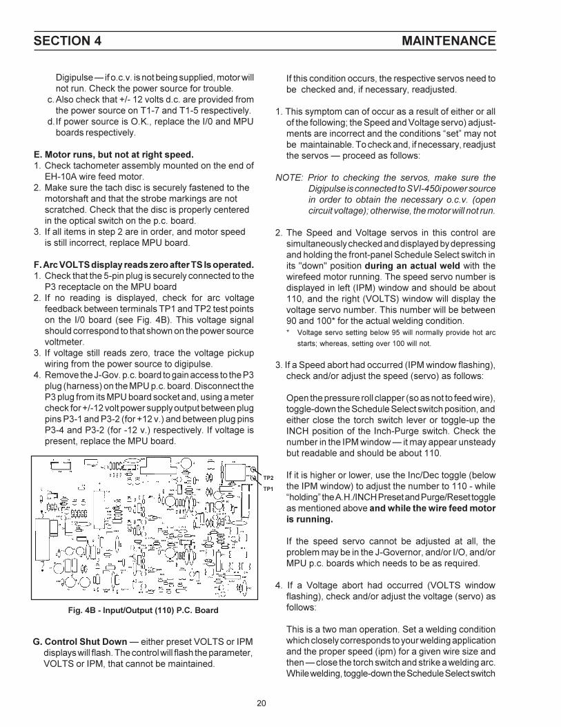
F. Arc VOLTS display reads zero after TS Is operated.1. Check that the 5-pin plug is securely connected to the
P3 receptacle on the MPU board2. If no reading is displayed, check for arc voltage
feedback between terminals TP1 and TP2 test pointson the I/0 board (see Fig. 4B). This voltage signalshould correspond to that shown on the power sourcevoltmeter.
3. If voltage still reads zero, trace the voltage pickupwiring from the power source to digipulse.
4. Remove the J-Gov. p.c. board to gain access to the P3plug (harness) on the MPU p.c. board. Disconnect theP3 plug from its MPU board socket and, using a metercheck for +/-12 volt power supply output between plugpins P3-1 and P3-2 (for +12 v.) and between plug pinsP3-4 and P3-2 (for -12 v.) respectively. If voltage ispresent, replace the MPU board.
SECTION 4 MAINTENANCE
Fig. 4B - Input/Output (110) P.C. Board
G. Control Shut Down � either preset VOLTS or IPMdisplays will flash. The control will flash the parameter,VOLTS or IPM, that cannot be maintained.
TP2
TP1

21
position and read the number displayed in the VOLTSwindow, it may appear unsteady but readable andshould be 95.
If the number is not in the 90-100 range, use the Inc/Dec toggle (below the VOLTS window) to adjust thenumber to 95 � while �holding� the toggle positionsmentioned above and while welding.
5. If the voltage servo cannot be adjusted, check forproper operation of the power source as follows:
a. Set the Digipulse voltage display to zero (thissetting will override the servo).
b. Place the Panel/Remote switch on the power sourcein PANEL position.
c. Make a weld by controlling the arc voltage directlyfrom the power source potentiometer.
d. If a weld can be made with good control over powersource voltage; a problem exists either in the inter-connecting voltage control cable, or in the Digipulsecontrol.
e. Check the control wires in the interconnectingvoltage control cable for continuity between theappropriate terminals in the power source anddigipulse using the schematic diagrams.
f. If continuity is correct, replace the I/O board and/orthe MPU board.
H. Control Shut-Down Due to Ground Fault Detec-tion � both IPM and VOLTS displays will flash.
The purpose of this circuit is to make sure that weldingcurrent is not present in the wire feeder frame/base,control box, or the equipment safety ground. If thisshould occur, the ground fault detector will temporarilyenergize and immediately terminate the weld. This abortis indicated by both visual displays flashing simulta-neously. � Before attempting to make a new weld, makesure that the Work Ground cable and its connections areproperly and securely made to the workpiece.
VIII. MAINTENANCE
If this equipment does not operate properly, stopwork immediately and investigate the cause of themalfunction. Maintenance work must be performedby an experienced person, and electrical work by atrained electrician. Do not permit untrained personsto inspect, clean, or repair this equipment. Use onlyrecommended replacement parts.
A. GENERAL MAINTENANCELittle maintenance is required to keep the wire feeder intop operating condition. It is important, however, thatmoving parts such as feed and pressure rolls, wire feedmotor, etc., be kept clean and free of dust or dirt.Cleaning is best accomplished by regularly blowing offthese parts with dry compressed air. This should be doneonce for every eight hours of operating time, more oftenif necessary.
B. LUBRICATION OF DIGITAL MOTOR-GEAR UNITThe EH-10A motor-gear digital unit is lubricated with aheavy duty grease when assembled at the factory andshould not require further lubrication unless disassembled.If disassembled relubricate with Texaco Multifak grease.
C. CHECK OR REPLACEMENT OF MOTOR BRUSHESMotor brushes should be checked periodically. If a brushis broken, or worn down to less than 3/8-in. length, it mustbe replaced. Brushes can be inspected by unscrewingthe brush-holder plug and withdrawing the brush assem-bly. Never remove a brush without matchmarking it andits holder, so that it can be replaced in the same holderin its original position.
D. REMOVAL OF EH-10A DIGITAL WELDING HEAD1. Unplug the control cables from the rear panel of the
wirefeeder control.2. Remove the accessory support assembly from the
motor-gear unit by loosening the cap screw at thebottom of the assembly.
3. Disconnect the motor and tachometer cables fromterminal board (T1) inside the control assembly asshown on the wiring diagram.
4. Remove the four screws which secure the digitalmotor-gear unit to the base and remove the digitalunit.
E. ADDITIONAL DIGIMIG PROGRAM FEATURESThe Digipulse�s MPU board contains an integral 4-rocker�dip� switch (SW1) that is factory-set to the followingpositions: Rocker #1 is CLOSED, and Rockers #2, 3, 4are OPEN. The microprocessor technology utilized bythe Digipulse control is extremely versatile and can bemodified for specific purpose by ESAB�s engineeringservices group. To add specific features or programs toyour unit, consult your ESAB representative. If additionaloptional features are provided, the SW1 rocker positionsmay need to be repositioned � and this information willbe conveyed in the appropriate instruction bookletsprovided with the option kits.
SECTION 4 MAINTENANCE

22
1. All replacement parts are keyed on the illustrations which follow. Order replacement parts by part number andpart name, shown on illustrations. DO NOT ORDER BY PART NUMBER ALONE.
2. Always state the series or serial number of the machine on which the parts are to be used. The serial number isstamped on the unit nameplate.
COVER - 30170YLWARNING DECAL - 2091514*
(SW1, 3, 5, 7) SWITCH - 950087 n
(2) ACCESSARY SUPPORT ASSY.2 ROLL DRIVE (See Fig. 8) - 49V51
LEFT TORCH (J4) RECEPTACLE -182W64C16 CAPACITOR672348
FRONT CONTROL SUPPORT - 35742
(2) EH-10A DIGITAL MOTOR-GEARUNIT ASSY. 679777 (See Fig. 6)
RIGHT TORCH (J3) RECEPTACLE- 182W64(C10, 11) CAPACITOR- 672348
WARNING DECAL - 995204*
Fig. 5 - DIGIPULSE Dual Wire Feeder, P/N 33299
n Recommended Spare Parts
CONTROL ASSY.33387 (see Fig. 7)
SECTION 5 REPLACEMENT PARTS
(MSL) POWER ON-OFF SW634517 n
STRAIN RELIEF - 96W76
uRUN-SET SW - 950956
(2) GAS INLET CONNECTION - 74S76
(2) GAS SOLENOID VALVE - 2062305 n
(2) GAS BULKHEAD ADAPTOR - 58V58
KNOCKOUT OPTIONALWATER CONNECTIONS (See Fig. 10)
REAR CONTROL SUPPORT36278
(J1) RECEPTACLE - 950762 (19-pin)C20 CAPACITOR - .1uf, 500 V
(2) SPINDLE ASSY.948259 (See Fig. 9)
POWER CABLE ADAPTOR BLOCK - 6741561/2-IN.-13 STL. NUT1/2-IN. LOCKWASHER(2) 1/2-IN. FLATWASHER
(VR) VOLTAGE REGULATOR includes:VOLTAGE REGULATOR - 950159TRANSISTOR SOCKET - 950158(C4) CAPACITOR - 995544
BASE w/SUPPOFT - 36279
Not Illustrated � Accy. SupportINSULATOR RING60N90Key - 28N33THUMBSCREW61351087FLATWASHER - 64309431BELLEVILLE WASHER - 950783
(CB) CIRCUIT BREAKER - 950874 n
* Replace decal if it becomesexcessively worn or lost whenreplacing panel(s)
n Recommended Spare Parts
u Replacement key for Run-Set SW - 32778
REAR VIEW
FRONT VIEW

23
TACH. P.C.B.D.675429(2) Screw-61324746
Gear Case Lubricated withTexac Multifak Grease
11.6
2.370
.93
.6251
MOTOR ENDHOUSING
TACH COVER - 18787(2) Screws 61324974
(Ref.) 54" LG
10
2.875
50DP
MIN.
VENT PLUG
3.25
2.000
5.16 18 UNC 2B
2.86
.25
4.010 SQ.2.25
1.3751.375
.25
END VIEWw/COVER REMOVED
63 MIN. DEPTH
MTR.LEAD
TACH DISK950313
.020REF
FOR MOTOR REPLACEMENTPARTS (See Fig. 6A)
TACH HOUSING - 18786(2) 8-32 X 3/8" Screw
33 LOCATING COLLAR(REF.)
Fig. 6 - EH-10A Digital Motor-Gear Unit Assembly (40:1) P/N 679777
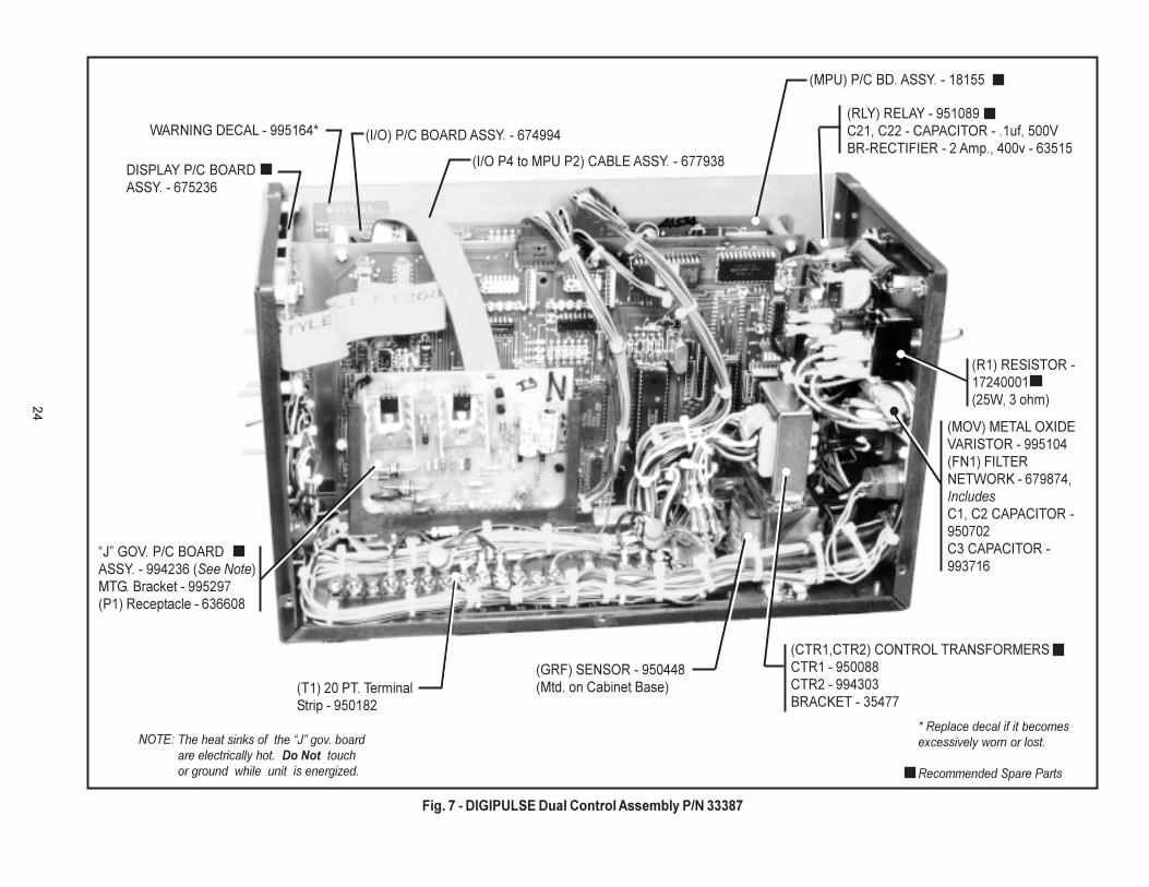
24
WARNING DECAL - 995164*
(T1) 20 PT. TerminalStrip - 950182
(GRF) SENSOR - 950448(Mtd. on Cabinet Base)
The heat sinks of the �J� gov. boardare electrically hot. Do Not touchor ground while unit is energized.
NOTE:
(MOV) METAL OXIDEVARISTOR - 995104(FN1) FILTERNETWORK - 679874,IncludesC1, C2 CAPACITOR -950702C3 CAPACITOR -993716
(I/O P4 to MPU P2) CABLE ASSY. - 677938
(I/O) P/C BOARD ASSY. - 674994
(MPU) P/C BD. ASSY. - 18155
(RLY) RELAY - 951089C21, C22 - CAPACITOR - .1uf, 500VBR-RECTIFIER - 2 Amp., 400v - 63515
(R1) RESISTOR -17240001(25W, 3 ohm)
DISPLAY P/C BOARDASSY. - 675236
�J� GOV. P/C BOARDASSY. - 994236 (See Note)MTG. Bracket - 995297(P1) Receptacle - 636608
(CTR1,CTR2) CONTROL TRANSFORMERSCTR1 - 950088CTR2 - 994303BRACKET - 35477
* Replace decal if it becomesexcessively worn or lost.
Recommended Spare Parts
Fig. 7 - DIGIPULSE Dual Control Assembly P/N 33387

25
CONDUIT
OUTLET
CLAMP - 61N02
SCREW 5/16" -18 X 2" LG
NUT 5/16"-18
ROLL PIN 3/16" X 1-3/4" LG
INLET
Fig. 8 - Accessory Support Assembly, P/N 49V51
5/8 -18 Lh
WATERCONNECTION58V75(OUTLET)
5/8 -18 Lh 1/4 N.P.T.
5/8 -18 Lh
COUPLING - 68121075
ADAPTOR - 11N16(INLET)
WATERCONNECTION58V75(OUTLET)
5/8 -18 Lh 1/4 N.P.T.
ADAPTOR - 11N16(INLET)
WATER SOLENOIDVALVE - 2062355
Fig. 9 - Spindle Assembly, P/N 948259,Optional Wire Reel, P/N 995570
WIRE REEL - 995570Includes:REEL - 995568COVER - 995569(4) WING NUT, 1/2" - 1363398183
(Ref. Hair Pin Clip)REEL
(4) .359" DIA. HOLE ON 3" DIA. D.C.
SPINDLE - 948258
"D" TYPEWASHER - 948254
SCREW -5/16" -18 x 2"
HAIR PINCLIP - 634347
WASHER -948256
SUPPORT -948257
SPRING - 948253
(2) BRAKE PAD - 948255
SPINDLE
HEAVY SPRING - 182W54 (FOR LARGE DIA. HARD WIRE)
PRESSURE ROLL28V52
BOLT 1/4" x 1-5/8"LGSPACER - 60N79
(2) LOCKING HANDLE ASSEM - 49V44
SET SCREW # 6-32 X 1/4" LG61330849
WIPER HOLDER*598764
INLET GUIDE INSERT05N58
INLET WIRE GUIDE29N13
ROLL PIN 1/4" X 1-3/4" LG
CLAPPER - 60N98 SHAFT - 60N65
KNOB - 60N68
LIGHT SPRING 182W55 (FORSOFT & SMALL DIA. HARD WIRE)
RETAINER 58N24
FORK - 49V43
*Outlet guide And Wiper Holder Not Included in Assembly Part No. 49V51.
WITHOUT SOLENOID VALVE
WITH SOLENOID VALVE
Fig. 10 - Water Kit with Solenoid Valve, P/N 2075760*Water Kit without Solenoid Valve, P/N 994466
*Do not use with Coolant Recirculator
INCLUDES:
SUPPLIED
WIRE OUTLET GUIDE*(See Table 1)
WIRE OUTLET GUIDE INSERT*

26
Digipulse Dual Control Revision History
Rev. A Added label P/N 954232 (Schedule Select) to front panel.
Rev. BRemoved the 6 pin (P/N 634772) and 8 pin (P/N 2062106) box receptacles and added a 19pin (P/N 950762) box receptacle P/N 950762. (Ref. Schematic Diagram Rev.A and WiringDiagram Rev. A).
Rev. CModified note 7 of the assembly drawing and added the accessory support leads 1&2 toT1-20 of the wiring diagram. (Ref. Schematic Diagram Rev.A and Wiring Diagram Rev. B).
Rev. DChanged from a green/light green cabinet with L-Tec decals to a gray/yellow cabinet withESAB decals, changed CTR1 and CTR2 from a welded assembly ,added mounting bracketP/N 35477, and changed the signal lead assembly from P/N 30685 to P/N 36644. TitleDigmig Dual was changed to Digipulse Dual. (Ref. Schematic Diagram Rev.B and WiringDiagram Rev. C).
Rev. EAdded Craterfill as a factory installed option.
Digipulse Dual Wire Feeder Revision History
Rev. ARe-designed the base and reel support , changed the color from L-Tec green to ESABgray/yellow.

27

F-15-496-A 5/99 Printed in U.S.A.
IF YOU DO NOT KNOW WHOM TO CALL
Telephone: (800) ESAB-123/ Fax: (843) 664-4452/Web: http://www.esab.com
Hours: 7:30 AM to 5:00 PM EST
ESAB Welding & Cutting Products, Florence, SC Welding EquipmentCOMMUNICATIONS GUIDE - CUSTOMER SERVICES
A. CUSTOMER SERVICE QUESTIONS: Telephone (843) 664-5540/Fax: (800) 634-7548Order Entry Product Availability Pricing Hours: 8:30 AM to 5:00 PM ESTOrder Changes Saleable Goods Returns DeliveryShipping Information
B. ENGINEERING SERVICE: Telephone: (843) 664-4416 / Fax : (800) 446-5693Welding Equipment Troubleshooting Hours: 7:30 AM to 5:00 PM ESTWarranty Returns Authorized Repair Stations
C. TECHNICAL SERVICE: Telephone: (800) ESAB-123/ Fax: (843) 664-4452Part Numbers Technical Applications Hours: 8:00 AM to 5:00 PM ESTPerformance Features Technical Specifications Equipment Recommendations
D. LITERATURE REQUESTS: Telephone: (843) 664-5501 / Fax: (843) 664-5548Hours: 7:30 AM to 4:00 PM EST
E. WELDING EQUIPMENT REPAIRS: Telephone: (843) 664-4469 / Fax: (843) 664-5557Repair Estimates Repair Status Hours: 7:30 AM to 3:30 PM EST
F. WELDING EQUIPMENT TRAINING :Telephone: (843)664-4428 / Fax: (843) 664-4476Training School Information and Registrations Hours: 7:30 AM to 4:00 PM EST
G. WELDING PROCESS ASSISTANCE :Telephone: (800) ESAB-123 / Fax: (843) 664-4454 Hours: 7:30 AM to 4:00 PM EST
H. TECHNICAL ASST. CONSUMABLES :Telephone: (800) 933-7070 Hours: 7:30 AM to 5:00 PM EST