dig aruba site survey
DESCRIPTION
Aruba Access PointTRANSCRIPT

Indoor Access Points:Site Survey and Planning
Pre
-Dep
loym
ent
Gui
de

Copyright
© 2007 Aruba Networks, Inc. All rights reserved.
Aruba Networks® is a registered trademark, and Aruba The Mobile Edge Company is a trademark of Aruba Networks, Inc. Specifications are subject to change without notice.
Trademarks
Sygate On-Demand Agent and Sygate Enforcer are trademarks of Sygate Technologies.All other trademarks or registered trademarks are the property of their respective holders.
Legal Notice
The use of Aruba Networks, Inc. switching platforms and software, by all individuals or corporations, to terminate Cisco or Nortel VPN client devices constitutes complete acceptance of liability by that individual or corporation for this action and indemnifies, in full, Aruba Networks, Inc. from any and all legal actions that might be taken against it with respect to infringement of copyright on behalf of Cisco Systems or Nortel Networks.
Warranty
This hardware product is protected by the standard Aruba warranty of one year parts/labor.For more information, refer to the ARUBACARE SERVICE AND SUPPORT TERMS AND CONDITIONS.Altering this device (such as repainting it) voids the warranty.
www.arubanetworks.com
1322 Crossman AvenueSunnyvale, California 94089
Phone: 408.227.4500Fax 408.227.4550
Indoor Access Points: Site Survey and Planning | Pre-Deployment Guide 0510297-01

Indoor Access Points: Site Survey and Planning | Pre-Deployment Guide
ContentsPreface Guide Overview 9
Related Documents 9
Contacting Aruba Networks 10
Chapter 1 Site Planning Basics 11Site Planning Overview 11
Getting Started 11
Chapter 2 Initial Environment Evaluation 13Determining the Environment Type 13
Wireless RF Coverage Considerations and Questionnaire 14Coverage-Based Model (Low Bandwidth) 14Capacity-Based Model (High Bandwidth) 15Custom-Based Model 15
Determining the Deployment Type 15
Chapter 3 Access Point and Antenna Selection 17Aruba AP and Antenna Selection Process 17
Aruba APs 18Application and Band Requirements 18
Air Monitoring Benefits 18Access Point Benefits 18
Aruba’s Indoor Single and Dual Radio APs 19
Aruba Antennas 20Understanding Wireless Antennas 20
Omni-Directional vs. Directional Coverage 20Antenna Beamwidth, Pattern, and Gain Considerations 21Understanding Antenna Pattern Plots and Specifications 23
Detachable Antenna Selection 24Detachable Indoor Antenna Types 24Detachable Antenna Selection Tips 24
Chapter 4 RF Plan Utilization 25
RF Plan Overview 25
Utilizing RF Plan 26Pre-requisites 26RF Planning Example 26
Task Overview 27Standard Deployment Planning Example 28
Chapter 5 Physical Site Survey 37Site Survey Overview 37
Standard Deployments 37Complex Deployments 37
Assessing the Environment 37Identifying Known RF Absorbers or Reflectors 37
Contents | 3

RF Absorbers 38RF Reflectors 38RF Interference Sources 38
Determining Correct Product Placement 38
Conducting Site Surveys 38Site Survey Pre-requisites 39Site Surveys for Standard Environments 39Site Surveys for Complex Environments 40
Appendix A Integral, Omni-Directional Antenna Positioning 43Ceiling Deployments 43
AP-60/61 43AP-65 44AP-70 45
Wall Deployments 46AP-60/61 46AP-65 47AP-70 48
Appendix B Successful Complex Deployments 49Complex Deployment Example: Bus Depot 49
Index 53
4 | Contents Indoor Access Points: Site Survey and Planning | Pre-Deployment Guide
Indoor Access Points: Site Survey and Planning | Pre-Deployment Guide
FiguresFigure 1 AP and Antenna Selection 17Figure 2 Omni-Directional Antenna 20Figure 3 Directional Antenna 21Figure 4 Equal Signal Strength Radiated in All Directions 21Figure 5 High Gain Omni-Directional Antenna 22Figure 6 High Gain Directional Antenna 22Figure 7 Antenna Pattern Conventions (Omni-Directional Pattern Shown) 23Figure 8 Donut Shape Compression of an Omni-Directional Antenna 23Figure 9 Add Campus Dialog Box 28Figure 10 Add Building Dialog Box: Dimensions 28Figure 11 Add Building Dialog Box: AP Modeling Parameters 29Figure 12 Add Building Dialog Box: AM Modeling Parameters 29Figure 13 Importing a Background Image/Floor Plan 30Figure 14 Modifying the Background Image 30Figure 15 Floor 1 Background Image 31Figure 16 Adding a Special Area 31Figure 17 Defining a Do Not Deploy Area 32Figure 18 Optimal AP Locations 32Figure 19 Optimal AM Locations 33Figure 20 Optimal AP and AM Locations 34Figure 21 Map Type: AP-802.11b/g; Coverage Rate: 54 Mbps; Channel: All: Merged 35Figure 22 Map Type: AM-802.11a; Coverage Rate: 36 Mbps 35Figure 23 AP-60/61 Integral, Omni-Directional Antenna Positioning 43Figure 24 AP-65 Integral, Omni-Directional Antenna Positioning 44Figure 25 AP-70 Integral, Omni-Directional Antenna Positioning 45Figure 26 Complex Deployment Floor Plan 49Figure 27 Complex Deployment AP and AM Placement 51Figure 28 Complex Deployment Coverage Pattern 52
Figures | 5

6 | Figures Indoor Access Points: Site Survey and Planning | Pre-Deployment Guide

Indoor Access Points: Site Survey and Planning | Pre-Deployment Guide
TablesTable 1 Web Site Support Contact List 10Table 2 Telephone Support Contact List 10Table 3 Aruba Indoor Access Points 19Table 4 Defined Parameters and Requirements 27Table 5 Defined Parameters and Requirements 50Table 6 Custom-Based Model for Capacity and Coverage 51
Tables | 7

8 | Tables Indoor Access Points: Site Survey and Planning | Pre-Deployment Guide

Indoor Access Points: Site Survey and Planning | Pre-Deployment Guide
PrefaceThis preface includes the following information:
An overview of the contents of this manual
A list of related documentation for further reading
Aruba Networks support and service information
Guide OverviewChapter 1 on page 11 highlights the key tasks involved and the sequence that they need to be performed in for accurate planning and surveying of a customer’s environment.
Chapter 2 on page 13 focuses on conducting an initial (pre-site survey) evaluation of the environment that an Aruba WLAN deployment is to take place in. This chapter provides key questions to ask and items to consider when deploying a wireless network.
Chapter 3 on page 17 provides information regarding Aruba’s indoor selection of access points (APs) and antennas. This chapter also provides key tools that will help you understand Aruba antenna specifications.
Chapter 4 on page 25 prepares you for using RF Plan as a tool for planning a WLAN deployment and provides a planning example of a standard deployment.
Chapter 5 on page 37 is full of useful tools and information that will help you complete an on-site walk-through and perform an accurate evaluation of the customer’s environment. This chapter is critical for accurate planning and surveying of a complex environment.
Appendix A on page 43 includes illustrations of Aruba’s various indoor APs and shows the proper placement of their omni-directional integral antennas.
Appendix B on page 49 provides an example, through description and illustrations, of a successful complex deployment.
Related DocumentsThe following documents are referred to in this guide and are considered components of the complete documentation set needed for successful, indoor site planning:
RF Plan Installation and User Guide
Aruba Access Point Installation Guides
Aruba Antenna Specifications
| 9
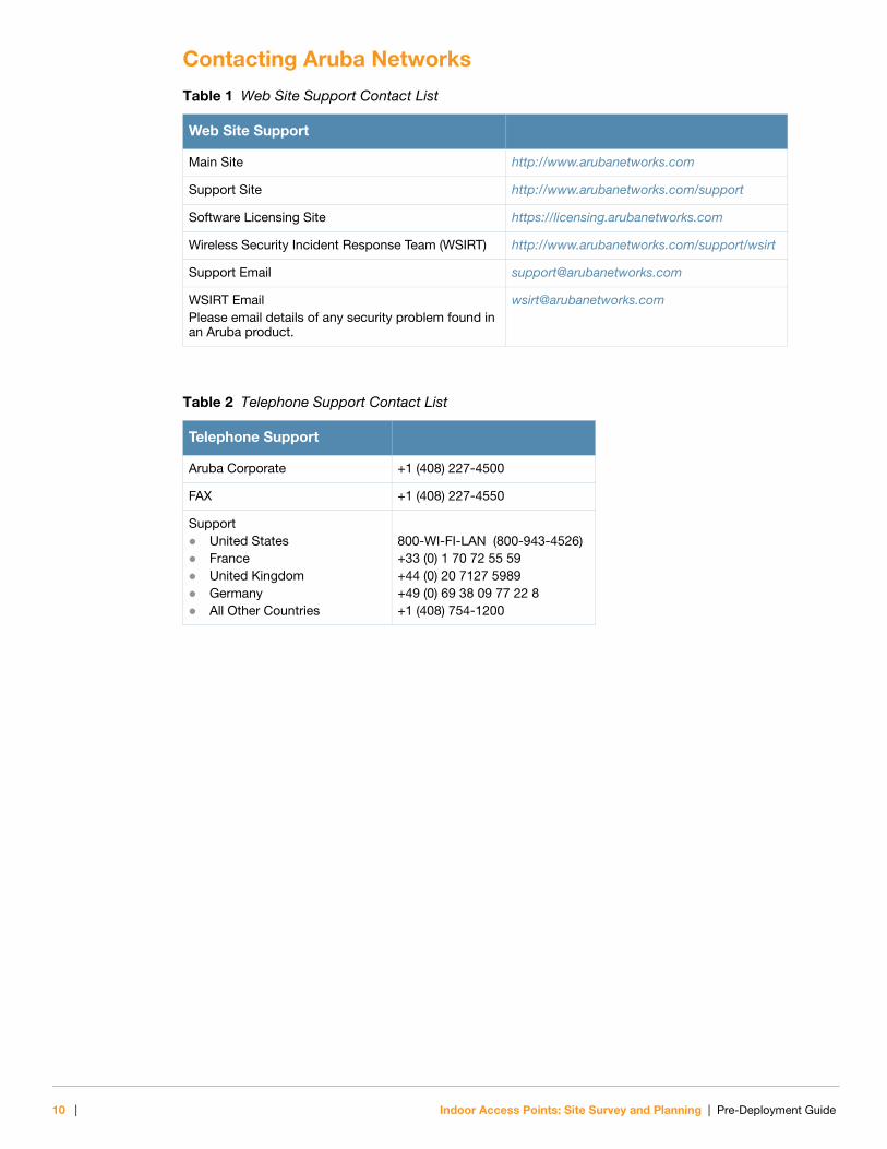
Contacting Aruba Networks
Table 1 Web Site Support Contact List
Web Site Support
Main Site http://www.arubanetworks.com
Support Site http://www.arubanetworks.com/support
Software Licensing Site https://licensing.arubanetworks.com
Wireless Security Incident Response Team (WSIRT) http://www.arubanetworks.com/support/wsirt
Support Email [email protected]
WSIRT EmailPlease email details of any security problem found in an Aruba product.
Table 2 Telephone Support Contact List
Telephone Support
Aruba Corporate +1 (408) 227-4500
FAX +1 (408) 227-4550
SupportUnited StatesFranceUnited KingdomGermanyAll Other Countries
800-WI-FI-LAN (800-943-4526)+33 (0) 1 70 72 55 59+44 (0) 20 7127 5989+49 (0) 69 38 09 77 22 8+1 (408) 754-1200
10 | Indoor Access Points: Site Survey and Planning | Pre-Deployment Guide

Indoor Access Points: Site Survey and Planning | Pre-Deployment Guide
Chapter 1Site Planning Basics
Site Planning OverviewThe purpose of this guide is to provide systems engineers, technical support engineers, and site survey teams with the tools needed to conduct a successful site survey and plan for the implementation of an Aruba wireless network.
Getting StartedPrior to deploying a wireless network, you must evaluate the environment and plan for a successful Aruba WLAN deployment. Successfully evaluating the environment enables the proper selection of Aruba APs and antennas and assists in the determination of their placement for optimal RF coverage.
To plan a successful WLAN deployment, follow these steps:
1. Perform an initial environment evaluation.
Knowing what to look for and what to ask are key tools for effectively determining the environment type and the appropriate deployment type. Aruba’s initial environment evaluation will provide you with these tools.
Refer to Chapter 2 on page 13 for complete details.
2. Select the proper APs and antennas for the deployment.
Understanding Aruba AP and antenna types will help you determine the products best suited for the environment, providing optimal performance and RF coverage.
Refer to Chapter 3 on page 17 for complete details.
3. Enter the collected/determined information into RF plan.
RF Plan is Aruba’s pre-deployment site planning tool. In most instances, a standard deployment can occur based on the RF Plan output without a physical site survey. For complex deployments, RF Plan can be used to generate a basic foundation for planning, but on-site verification of AP location and signal coverage is recommended for complex environments.
Refer to Chapter 4 on page 25 for complete details.
4. Conduct a physical site survey (if applicable).
To properly identify RF absorbers and reflectors, conduct a physical site survey. Identifying key worst case challenges in the installation environment may be critical when determining AP location. A walk-through is crucial for effectively planning a WLAN deployment in a complex environment.
Refer to Chapter 5 on page 37 for complete details.
5. Make adjustments to RF Plan (if applicable).
N O T E
This guide assumes an understanding of RF (radio frequency) and WLAN networking technology, terminology, and industry standards. Planning of an Aruba wireless network should be done by a certified wireless network administrator (CWNA) or the equivalent.
Site Planning Basics | 11
Once a physical site survey has been conducted, the identification of RF absorbers and reflectors might impact actual AP locations. Changes can be made to the floor plan to adjust for these findings.
Refer to Chapter 4 on page 25 for complete details.
6. Install the selected APs and directional antennas (if applicable).
7. Configure the APs (manage spectrum usage).
N O T E
Installation and configuration are not covered in this guide. Once you have completed the site survey and planned for a WLAN deployment with optimal RF coverage, refer to the Aruba Access Point Installation Guide for the AP type(s) that you are deploying. For information on proper antenna positioning, refer to Appendix A on page 43.
12 | Site Planning Basics Indoor Access Points: Site Survey and Planning | Pre-Deployment Guide

Indoor Access Points: Site Survey and Planning | Pre-Deployment Guide
Chapter 2Initial Environment Evaluation
Follow the guidelines in this chapter to help you assess the environment and determine the best course of action for implementation of a complete and successful Aruba WLAN solution. This process must be completed before you can determine the correct AP and antenna types for the deployment.
Determining the Environment TypeWhat category does the environment fall into?
Standard: Typical Office Environments
Standard deployments primarily consist of APs with integral, omni-directional antennas deployed at the ceiling level.
RF Plan is Aruba’s site planning tool. With the information that you provide, RF Plan will generate an output that can be deployed without a physical site survey. Once the plan is deployed and the APs are in place, Aruba’s real-time dynamic site survey tool, Adaptive Radio Management (ARM), provides automatic self-configuration of all radio parameters, including transmit power level, channel, load-balancing, and interference avoidance. If needed, a limited site survey can be conducted to identify RF absorbers/reflectors or other circumstances that warrant relocation of an AP. These adjustments are later entered back into RF Plan.
Complex: Warehouses, Manufacturing Plants, Aircraft Hangers, Bus Depots, Lecture Halls, Convention Centers, Historical Buildings and Tradeshows
Complex deployments primarily involve high ceilings and are often loaded with large RF absorbers/reflectors, such as metal racks, trucks, or aircrafts, requiring the implementation of directional antennas.
Historical buildings are considered complex due to potential asbestos above the ceiling tiles and/or problems faced when encountering older RF blocking building materials, such as concrete, rebar, and metal pans between floors.
RF Plan can be used to generate a basic foundation for planning, but RF plan does not allow for the implementation of directional antennas. Due to this constraint, on-site verification of AP location and signal coverage is recommended for complex environments.
N O T E
Hospitals may fall into either category and must be assessed on a case by case basis. The ceiling type and type of RF blocking equipment used in hospitals will determine the category. If hospital construction is new, the deployment is similar to a typical office environment. However, if it's an existing hospital, a ceiling deployment may not be possible due to the ceiling material type or severe amounts of dust above the ceiling tile that cannot be allowed to fall down and onto beds or patients. Keep these factors in mind for all buildings consisting of older construction materials that include asbestos or RF blocking materials.
Initial Environment Evaluation | 13

Wireless RF Coverage Considerations and QuestionnaireAnswers to these questions will help you determine the proper Aruba AP type, prepare for the site survey, and plan appropriately for the deployment.
What 802.11 PHY types are desired (802.11a/b/g)?
What brand(s) of NICs and client devices will be used?
What are the desired data traffic rates?
What are the desired air monitoring rates?
What is the maximum number of users desired for each AP?
What are the user counts for each floor of the building?
What are the user counts for each building of the campus?
Are any floor plan images available?
Formats compatible with Aruba’s offline RF Plan application are AutoCAD files (.dwg, .dwf, or .dxf) or .jpg, .jpeg, and .png formats.
What applications will be in use at the site, both presently and in the future?
This information will help determine the need for a coverage-based or capacity based model. Applications also impact AP placement (height and inter-AP spacing).
Determining the Model Type
Coverage-Based Model (Low Bandwidth)The coverage-based model is for low-bandwidth deployments, where low roaming wireless signal coverage is required for applications such as a scanner solution or guest access. A coverage-based deployment might consist of APs placed roughly 100 to 200 feet (approx. 30.5 to 61 meters) apart running at 50-75% of power.
For example, if the determined application is a scanning solution with minimal traffic, the site might be a good candidate for a coverage-based model. The deployment would consist of an AP installation base with clients associating at greater distances and at lower traffic rates. This coverage model would most likely mandate a ceiling deployment.
N O T E
Please note that Aruba’s Adaptive Radio Management (ARM) tool is activated through a configuration setting and its activation is recommended for ALL model types. A capacity-based model requires the activation and utilization of ARM for self-healing. A coverage-based model does not include self-healing but it can utilize the rest of ARM’s features. ARM should cycle for at least one full day (24 hours) before its maintain configuration setting is activated.
14 | Initial Environment Evaluation Indoor Access Points: Site Survey and Planning | Pre-Deployment Guide

Capacity-Based Model (High Bandwidth)The capacity-based model is for dense deployments with high traffic rates, due to the number of users and the types of applications they'll be accessing. A capacity-based deployment might consist of APs placed roughly 45 to 60 feet (approx. 13.75 to 18.25 meters) apart running at 25-50% or 50-75% of power.
For example if the requirement is a “desk-top like” experience for employee laptops, where the employee may be running multiple applications simultaneously, the site would require a capacity-based deployment. The deployment would include a dense AP installation base with clients associating at closer distances and at higher traffic rates. This coverage model may allow for a deployment below the ceiling level.
Custom-Based ModelNot all sites fall into one category or the other and a custom-based model may be required. A custom-based model can cater to diverse needs and may include both capacity-based and coverage-based deployments throughout various parts of the site. For instance, a custom model might consist of a site that requires a capacity-based model for its office area and a coverage-based model for its warehouse area. Custom-based models are often needed for complex deployments.
Determining the Deployment TypeWhat type of deployment is best suited for the environment?
Ceiling Deployments: The majority of deployments are at the ceiling level. An AP should not be deployed at the ceiling level if the ceiling tile material is an RF absorber/reflector. A ceiling deployment can occur at, below, or above the level of the ceiling tiles.
Wall Deployments: Wall deployments are not as common as ceiling deployments. Wall installations are used as needed for special circumstances, such as moving an AP away from an RF absorber/reflector. Wall deployments may also occur in enviornments where a false ceiling does not exist and where cabling cannot be run.
Indoor Access Points: Site Survey and Planning | Pre-Deployment Guide Initial Environment Evaluation | 15

16 | Initial Environment Evaluation Indoor Access Points: Site Survey and Planning | Pre-Deployment Guide

Indoor Access Points: Site Survey and Planning | Pre-Deployment Guide
Chapter 3Access Point and Antenna Selection
For optimal performance of your wireless network it is essential to understand the purpose behind proper AP and antenna selection. Choosing the correct AP and antenna type will ensure that application and band requirements are being met and that RF energy is being directed to the correct coverage areas.
Aruba AP and Antenna Selection ProcessPlease follow the process flow depicted in Figure 1 to determine the correct AP and antenna type needed for the deployment. This chapter provides critical information and decision making tools to guide you through the selection process.
Figure 1 AP and Antenna Selection
arun_008
Determine the Applicationand Band Requirements
Select the AP Type:Single or Dual Radio
Select Antenna Type:Omni-Directional vs.
Directional
Single Radio APRequired
Dual Radio APRequired
Select the Detachable,Directional Antenna Type
Select the Detachable,Omni-Directional Antenna (if applicable)
Note: The AP-70 does allow for theimplementation of a higher-gain,
detachable, omni-directional antenna.
Single RadioOmni-Directional APs:
AP-61 or AP-41
Dual RadioOmni-Directional APs:
AP-65 or AP-70
Single RadioDirectional AP: AP-60
Dual RadioDirectional AP: AP-70
N O T E
Integral, omni-directional antennas provide mid to high-gain performance over the entire frequency band that the AP supports. Detachable antennas, omni-directional or directional, are selected when a higher level of gain performance is required. Directional antennas are selected for their ability to direct RF energy to a targeted coverage area. Most indoor deployments utilize omni-directional antennas. Refer to Omni-Directional vs. Directional Coverage on page 20 for further details.
Access Point and Antenna Selection | 17

Aruba APs
Application and Band RequirementsAre dedicated air monitors (AMs) needed, will the access points (APs) be dedicated to WLAN service, or with the APs provide both WLAN service and AM functions simultaneously?
An Aruba access point can be configured as a thin access point that provides 802.11a/b/g wireless access to users, as an air monitor that constantly scans the RF spectrum, or as a scanning AP that provides both AP and AM functions simultaneously.
Air Monitoring Benefits
Air monitors perform advanced scanning of the RF environment, providing advanced capabilities in location and security services.
AMs act as sensors that constantly scan the RF environment for better resolution of location service.
Dedicated AMs are capable of detecting ad-hoc networks and rogue APs (an AP not sanctioned or authorized by network administrators). For optimal security, simultaneous monitoring of both traffic bands, 2.4 GHz and 5 GHz, is preferred. Dual radio APs, such as the AP-70 and AP-65, are capable of scanning both bands simultaneously. Single radio APs, such as the AP-41, AP-60, and AP-61, can be set to scan each band one at a time; the AP scans the entire 2.4 GHz band and then it scans the entire 5 GHz band.
Aruba AMs are capable of packet capture, which can grab client traffic, an entire channel, or can scan all channels. Grabbing a channel can be used for troubleshooting a client that can’t associate to an AP.
Aruba AMs are capable of scanning all country domains.
Since AMs do not need to time slice with clients, AMs scan the environment at faster rates than scanning APs.
Access Point Benefits
Dedicated Access Points
Dedicated APs service clients only. For dedicated WLAN service, determine the band requirements.
If the AP must service both bands, 2.4 GHz and 5 GHz, simultaneously, optimal performance is achieved by using one of Aruba’s dual radio APs: the AP-65 or the AP-70.
If single band client service is required, select a single radio AP that is capable of operating in only one mode at a time, 2.4 GHz or 5 GHz. Aruba’s indoor single radio AP selection consists of the AP-41, the AP-60, and the AP-61.
N O T E
Aruba access points double perfectly well as air monitors and as access points, but dedicated devices provide a number of security-related enhancements over scanning APs with multiple responsibilities.
N O T E
Most AMs use omni-directional antennas, which provides AMs with the ability to scan for threats in multiple directions.
18 | Access Point and Antenna Selection Indoor Access Points: Site Survey and Planning | Pre-Deployment Guide
Scanning Access Points
In scanning mode, an AP can perform WLAN and AM functions by servicing clients and continuously scanning the environment (detecting ad-hoc networks and rogue APs), but some performance impact is unavoidable with off-channel scanning. Specifically, rogue-AP protection (not detection) will impact the clients associated to that AP by as much as ~40% throughput loss. If rogue-AP protection is not required or if the hit can be taken, functions such as triangulation, dynamic RF management, wireless IDS, and remote-pcap can be performed from a scanning AP.
Any Aruba AP can be dynamically configured into AM mode. Dual-radio APs such as the AP-70 can operate one radio in AP mode (i.e. servicing clients on 2.4 GHz band) and the other in AM mode (i.e. scanning on 5 GHz band). As an AM, a radio goes into “listen-only” mode and continuously scans all channels in its band. An AP automatically provides monitoring on its configured channel. For example, an AP servicing clients on channel 1 provides full monitoring on channel 1. If set to perform off-channel scanning, the AP spends brief time intervals scanning other channels in the band. The shorter the scan interval, the less the impact on client performance.
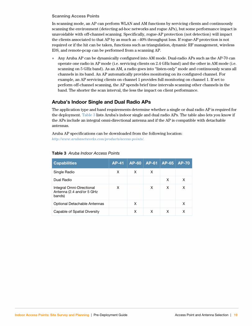
Aruba’s Indoor Single and Dual Radio APsThe application type and band requirements determine whether a single or dual radio AP is required for the deployment. Table 3 lists Aruba’s indoor single and dual radio APs. The table also lets you know if the APs include an integral omni-directional antenna and if the AP is compatible with detachable antennas.
Aruba AP specifications can be downloaded from the following location: http://www.arubanetworks.com/products/access-points/.
Table 3 Aruba Indoor Access Points
Capabilities AP-41 AP-60 AP-61 AP-65 AP-70
Single Radio X X X
Dual Radio X X
Integral Omni-Directional Antenna (2.4 and/or 5 GHz bands)
X X X X
Optional Detachable Antennas X X
Capable of Spatial Diversity X X X X
Indoor Access Points: Site Survey and Planning | Pre-Deployment Guide Access Point and Antenna Selection | 19

Aruba AntennasBefore you can select the antenna type needed for the deployment, read the basic wireless antenna information provided in this section. This information will help you understand wireless antenna basics and Aruba antenna specifications.
Understanding Wireless Antennas
Omni-Directional vs. Directional Coverage
For optimal performance of your wireless network, it is essential to understand the purpose behind proper antenna selection. Choosing the correct antenna type will ensure that RF energy is being directed to the correct coverage areas. Omni-directional antennas provide equal coverage in all directions (see Figure 2), while directional antennas point RF energy in a specific direction for RF concentration within a targeted area (see Figure 3). Integral, omni-directional antennas provide mid to high-gain performance over the entire frequency band that the AP supports. Detachable antennas, omni-directional or directional, are selected when a higher level of gain performance is required.
In general, directional antennas are not needed for indoor deployments and should be avoided except in special cases where coverage cannot be achieved by omni-directional antennas due to mounting location restrictions. Omni-directional antennas provide the best complement to key Aruba features for the indoor environment, such as ARM, location tracking, and RF plan/heat map presentations. In addition, the use of directional antennas is more likely to lead to 'hidden node' problems if not planned carefully.
Figure 2 Omni-Directional Antenna
Antenna LocationArea of CoverageDirection of Coverage
20 | Access Point and Antenna Selection Indoor Access Points: Site Survey and Planning | Pre-Deployment Guide

Figure 3 Directional Antenna
Antenna Beamwidth, Pattern, and Gain Considerations
Antenna gain is a relative measure of how the antenna compares to an ideal isotropic radiator. An ideal, isotropic radiator would radiate power in all directions equally over a sphere. The relationship between gain, power, and propagation distance is detailed already in textbooks and Wiki's, so these expressions are not repeated here. Antenna gain is often confused with power gain in amplifiers, but it is important to note that antenna gain only makes a transmitter's power appear to be higher than would be predicted by calculation of the power fed to the antenna and then spread equally over a sphere. Antenna gain itself is a completely passive and bi-directional property, determined only by the shape and construction of the antenna.
Knowing that gain is only a comparison of the apparent power to the power that would be required if fed to an ideal isotropic antenna, you realize that gain can only be created by distorting the antenna pattern from the ideal spherical pattern. Think of this as focusing the same power that would normally distribute evenly over a sphere into a tighter region of space. Thus, the higher the gain, the more concentrated (in some way) the antenna pattern must be in order to achieve that gain.
Example
To visualize the concept of gain, picture a rubber ball. The surface area of the ball represents the total available power radiated by an ideal isotropic antenna over its sphere of radiation (see Figure 4).
Figure 4 Equal Signal Strength Radiated in All Directions
Antenna LocationArea of CoverageDirection of Coverage
Equal Signal Strength Radiated over a Sphere
Indoor Access Points: Site Survey and Planning | Pre-Deployment Guide Access Point and Antenna Selection | 21

Now, still using the same ball with the same available surface area, how would you be able to stretch the ball farther out? One way is to press down on the top of the ball and squash it down vertically. This would keep the same basic shape in the horizontal plane (round), but it would force the ball to stretch, creating a pancake shape, in the vertical direction (see Figure 5). This represents the concept of the high gain omni-directional antenna, which achieves a greater coverage distance in the horizontal direction at the expense of coverage in the vertical areas of the radiating sphere.
Figure 5 High Gain Omni-Directional Antenna
To stretch the ball primarily in one direction (instead of in all directions), push the ball, both vertically and horizontally, on the sides and on the back, to force the ball to deform in a single direction. This action would significantly distort the shape of the original ball both horizontally and vertically, but it will allow you to stretch the same ball a lot farther in one direction (see Figure 6). This represents the concept of the high gain directional antenna, which is designed to compress the entire radiating sphere into a single predominate direction.
Figure 6 High Gain Directional Antenna
High Gain Omni-Directional Antenna
Compressed vertical signal, which expands signal horizontally
N O T E
Gain is created by forcing transmitted power to radiate in a preferred direction rather than radiating in all directions of an ideal sphere. Therefore, a high gain signal is always accompanied by loss of available signal in some other portion of the ideal sphere. High gain directional antennas are ideal for sites requiring directed coverage in a specific area or extended range for bridging applications, but they are not suited for sites requiring uniform coverage in large areas. It is important to keep in mind that both vertical and horizontal coverage can be affected by the use of a higher gain antenna and beamwidth (a measure of coverage) is always inversely related to gain.
High Gain Directional Antenna
Entire sphere compressed into a single predominate direction, focusing
22 | Access Point and Antenna Selection Indoor Access Points: Site Survey and Planning | Pre-Deployment Guide

Understanding Antenna Pattern Plots and Specifications
Traditional 2-D pattern plots and beamwidth specifications are like mental puzzles waiting to be solved because they only provide a snapshot of the information in two planes. These two planes are often referred to as the azimuth (H-plane or horizontal) and elevation (vertical or E-plane) planes. The azimuth view would be considered the view from directly above, viewing the antenna pattern on the horizontal plane. The elevation view is considered to be a side view, viewing the antenna pattern on the vertical plane. It is helpful to think of these planes as “cuts” of the real antenna pattern, which is actually 3-D. Figure 7 illustrates where these “cuts” are located for a typical omni-directional antenna pattern.
Figure 7 Antenna Pattern Conventions (Omni-Directional Pattern Shown)
The antenna illustrated by Figure 7 is commonly referred to as the dipole pattern because it is the pattern produced by an ideal dipole antenna. The gain of this antenna is 2.14, which is achieved by compression in the vertical plane (elevation) compared to the ideal sphere. If referring to the true 3D pattern, this compression is sometimes called the donut shape (see Figure 8).
Figure 8 Donut Shape Compression of an Omni-Directional Antenna
Azimuth, H-plane, or Horizontal Pattern Diagram
Elevation, E-plane, or Vertical Pattern Diagram
Indoor Access Points: Site Survey and Planning | Pre-Deployment Guide Access Point and Antenna Selection | 23

It is evident from Figure 7 that 2-D pattern plots typically provided in antenna specifications are a simplification of the real 3-D situation. Often, 2-D plots are reduced even further to a set of simple specifications based on the antenna gain and 3 dB beamwidth.
Detachable Antenna SelectionIf the AP supports detachable antennas, select the correct antenna type to support the required frequency band (2.4 GHz or 5 GHz) and desired coverage pattern.
To select the correct antenna type for the deployment, download and read Aruba’s indoor antenna specifications: http://www.arubanetworks.com/products/access-points/antennas/.
Detachable Indoor Antenna Types
These are some of the terms used to describe Aruba’s detachable antenna offerings. Terminology and degree of sector in Aruba’s antenna specifications are determined by the elevation or horizontal beamwidth.
Down-Tilt: An omni-directional antenna that focuses its energy downwards. Used for ceiling deployments in dense areas or in areas with high ceilings, such as manufacturing or warehouse environments.
Sector/Patch: This is a directional antenna that provides a focused sector of coverage from a central point (example: 90 degrees from center point).
Panel: This is typically a wall mounted, flat formed antenna that directs energy to a sector of coverage.
Detachable Antenna Selection Tips
If omni-directional coverage is desired but with a higher gain coverage than the integral antenna supports, select one of Aruba’s detachable antennas with high-gain, omni- directional coverage.
If the application type is air monitoring with a single radio AP, the detachable antenna must be capable of supporting all of the frequency bands that you want to support (2.4 GHz and/or 5 GHz). If you want to provide multi-band support, the antenna must be multi-band capable (AP-ANT-1B is the only detachable antenna capable of omni-directional, multi-band support).
If a directional antenna is required to direct RF coverage, the detachable antenna must be capable of supporting all of the frequency bands that require support (2.4 GHz and/or 5 GHz).
Directional antennas are selected to focus RF energy more efficiently.
Directional antennas are used in areas with odd shapes, such as in long corridors or in abnormally shaped buildings. For example, deploying the correct, directional antenna at each end of a long corridor will target the RF energy down the corridor in the correct pattern without wasting energy by using multiple, omni-directional antennas.
Directional antennas are useful in areas where the surrounding materials have high amounts of RF attenuation and the RF signal needs to be guided in the direction of the least amount of attenuation. For example, libraries that include metal stacks and shelves, or warehouses with metal racks containing goods.
Directional antennas are also used in areas with limited AP mouting options. For example, a large open room with an ornate ceiling that does not allow for the mounting of APs on the ceiling can benefit from directional antennas in each corner of the room, pointing RF signals inward in a sectorized approach.
Directional antennas are also used in dense deployments where low-gain coverage is desired, covering smaller geographical areas for concentrated coverage due to a high activity level within each cell.
24 | Access Point and Antenna Selection Indoor Access Points: Site Survey and Planning | Pre-Deployment Guide

Indoor Access Points: Site Survey and Planning | Pre-Deployment Guide
Chapter 4RF Plan Utilization
RF Plan OverviewAruba’s offline RF Plan application provides tools for pre-deployment RF planning. RF Plan allows you to determine access point placement based on the determined coverage and capacity requirements without impacting the live network. Using this tool, you can design new wireless network areas, such as campuses, buildings, and floors, and enter settings to provision and connect access points (APs) and/or air monitors (AMs) within the areas.
Using AutoCAD drawing (.dwg, .dwf, or .dxf files) formats, you can replicate physical site perimeters and apply them against AP and/or AM coverage parameters. Using .jpg, .jpeg, or .png formats, you can import and establish a background image for the floor. RF Plan uses this data to compute the most effective quantities and positions for the wireless equipment throughout the installation site depicted in your RF Plan images.
After the equipment (such as APs, AMs, or controllers) are physically installed, the floor plan(s) can be uploaded from RF Plan to the ArubaOS WebUI RF Plan or Mobility Management System (MMS) RF Live application for use with the live network.
This chapter assumes that you have already read the offline RF Plan Installation and User Guide for the application version that you are using. The RF Plan Installation and User Guide describes how to install the software and the functionality of the offline RF Plan application.
The purpose of this chapter is to provide examples of the RF Plan application in use and to walk you through the RF planning process for a basic office deployment.
N O T E
If you plan on importing the plan into the ArubaOS WebUI once the network is deployed, use .jpg or .jpeg images only. ArubaOS WebUI does not support any other formats. Aruba’s MMS RF Live application supports all of the formats that RF Plan accepts.
N O T E
The steps and screen shots in this chapter are based on RF Plan version 1.0.2.0. If you are using a different version of RF Plan, your version may vary slightly, but the thought process behind the planning is the same and the information can be applied, with slight modifications, to the version you are using.
RF Plan Utilization | 25

Utilizing RF Plan
Pre-requisitesBefore planning a deployment using Aruba’s offline RF Plan application, ensure that you have completed the following:
1. Conducted an Initial Environment Evaluation.
Refer to Chapter 2, “Initial Environment Evaluation” on page 13 for complete details.
2. Selected the appropriate AP and antenna types for the deployment.
Refer to Chapter 3, “Access Point and Antenna Selection” on page 17 for complete details.
3. Read and studied the RF Plan Installation and User Guide.
This guide can be downloaded from the Aruba customer support site: http://www.arubanetworks.com/support.
RF Planning ExampleIt is essential to gather all of the appropriate information during the planning phase to create a successful WLAN plan output using the RF Plan application. Once the Initial Environment Evaluation information is gathered and you have determined the appropriate Aruba products and WLAN requirements, you are ready to plan a wireless network using RF Plan.
The planning example included in this chapter covers a standard deployment in a typical office-like environment using a capacity-based model.
During the Initial Environment Evaluation, it was determined that the site required dedicated APs providing WLAN service and dedicated security AMs for both radio bands, 2.4 and 5 GHz. These APs and AMs needed to provide simultaneous coverage on both bands. The best Aruba AP choice for this type of environment is the AP-65 or the AP-70. The example in this chapter utilizes the AP-70. The AP-70 was chosen because it provides a larger AP or AM footprint due to a higher gain antenna.
N O T E
You must complete the above steps to gather the required information needed to plan a successful WLAN environment using the offline RF Plan application.
N O T E
The example in this chapter is based on a single floor building. In a multi-floor building, the AP-70 may lose some vertical coverage between floors due to its higher gain antenna, which compresses the vertical signal and expands the horizontal signal. The AP-65 provides a greater vertical signal for penetration through floors due to its lower gain antenna.
26 | RF Plan Utilization Indoor Access Points: Site Survey and Planning | Pre-Deployment Guide

Table 4 includes the defined parameters and requirements for the site used in this planning example.
Task Overview
In the following RF Plan example, you will perform the following:
1. Create a campus.
2. Add a building to the campus, enter its dimensions, and specify the number of floors (one).
3. Enter AP modeling parameters for the building.
4. Enter AM modeling parameters for the building.
5. Import a background image (floor plan) for a single floor building.
6. Define a Do Not Deploy area.
7. Initialize APs and AMs.
8. Optimize AP and AM locations.
9. Save and print the RF Plan output.
10. View coverage maps if desired.
Table 4 Defined Parameters and Requirements
Building Dimensions
Width 200 feet
Length 125 feet
Number of Floors One
User and AP Information
Number of Users 100
Users per AP 8
Radio Type(s) 802.11 a/b/g
Overlap Factor 150%
AP Type AP-70
AP Desired Rates
802.11 b/g 54 Mbps
802.11 a 54 Mbps
AM Desired Rates
802.11 b/g 5.5 Mbps
802.11 a 36 Mbps
Indoor Access Points: Site Survey and Planning | Pre-Deployment Guide RF Plan Utilization | 27

Standard Deployment Planning Example
1. Launch the RF Plan application.
2. Select File > New > Campus to display the Add Campus dialog box.
3. Enter My Campus in the Campus Name field and click Ok (see Figure 9).
Figure 9 Add Campus Dialog Box
4. From the navigation tree, right-click on My Campus.
5. Select Add Building to display the Dimensions page of the Add Building dialog box.
6. Enter My Building in the Name field (see Figure 10).
7. Enter the building dimensions and number of floors specified in Table 4 (see Figure 10).
Figure 10 Add Building Dialog Box: Dimensions
8. Click Next to display the AP Modeling Parameters page of the Add Building dialog box.
N O T E
The following naming conventions will be used in this example: My Campus, My Building, and Floor 1.
Enter the campus name.
Enter the building name and building dimensions, and define the number of floors.
28 | RF Plan Utilization Indoor Access Points: Site Survey and Planning | Pre-Deployment Guide

9. Select the Capacity radio button to define a capacity-based model for the wireless network (see Figure 11).
10. Enter the AP modeling parameters specified in Table 4 (see Figure 11).
Figure 11 Add Building Dialog Box: AP Modeling Parameters
11. Click Next to display the AM Modeling Parameters page of the Add Building dialog box.
12. Select the Coverage radio button to define a coverage-based air monitoring model for the wireless network.
13. Select the AM modeling parameters specified Table 4 (see Figure 12).
Figure 12 Add Building Dialog Box: AM Modeling Parameters
14. Click Finish to enter the settings and return to the main window.
Select a radio button to define the WLAN model type: coverage-based, capacity-based, or custom-based model.
Select or enter the correct AP modeling parameters for the site.
Based on the defined parameters, RF Plan automatically generates the number of APs for each field.
Select the correct AM modeling parameters for the site.
Based on the defined parameters, RF Plan automatically generates the number of required AMs.
Indoor Access Points: Site Survey and Planning | Pre-Deployment Guide RF Plan Utilization | 29

15. From the navigation tree, right-click on Floor 1 and select Set Background. The Open dialog box displays in the foreground and the Background Image Setup dialog box displays in the background (see Figure 13).
16. Browse to the location of the floor plan image and click Open (see Figure 13). The Open dialog box closes and the Background Image Setup dialog box activates.
Figure 13 Importing a Background Image/Floor Plan
17. Modify/crop the background image if needed and click Ok to return to the main window (see Figure 14). When you return to the main window, Floor 1 is active and the floor plan is displayed in the viewing pane.
Figure 14 Modifying the Background Image
30 | RF Plan Utilization Indoor Access Points: Site Survey and Planning | Pre-Deployment Guide
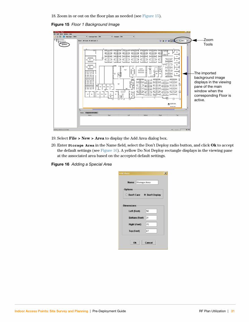
18. Zoom in or out on the floor plan as needed (see Figure 15).
Figure 15 Floor 1 Background Image
19. Select File > New > Area to display the Add Area dialog box.
20. Enter Storage Area in the Name field, select the Don’t Deploy radio button, and click Ok to accept the default settings (see Figure 16). A yellow Do Not Deploy rectangle displays in the viewing pane at the associated area based on the accepted default settings.
Figure 16 Adding a Special Area
Zoom Tools
The imported background image displays in the viewing pane of the main window when the corresponding Floor is active.
Indoor Access Points: Site Survey and Planning | Pre-Deployment Guide RF Plan Utilization | 31

21. Click and drag the Do Not Deploy rectangle over the Storage Area on the floor plan (see Figure 17). Use your mouse to click on any corner of the rectangle and stretch and fit the rectangle over the Storage Area. The exact Do Not Deploy location displays on the Area tab (see Figure 17).
Figure 17 Defining a Do Not Deploy Area
22. Click the Initialize APs button on the RF Plan toolbar to initialize APs and display them on the floor plan (see Figure 18).
23. Click the Optimize APs button on the RF Plan toolbar to optimize the location of the APs (see Figure 18). RF Plan will automatically calculate the optimal position for each AP and it will move the APs to the suggested locations. The Suggested APs/AMs tab will update with the suggested location information for each AP. If desired, you can click and drag an AP to a preferred location.
Figure 18 Optimal AP Locations
Click, drag, and modify the Do Not Deploy yellow rectangle over the area where you do not want APs deployed.
The rectangle in this image represents the Do Not Deploy Storage Area for this planning example.
Information regarding defined special areas displays on the Area tab.
Optimize APs Button
Initialize APs Button
List of Suggested AP Locations
AP icons display in suggested locations.
32 | RF Plan Utilization Indoor Access Points: Site Survey and Planning | Pre-Deployment Guide

24. Click the View APs button to turn off the APs.
25. Click the Initialize AMs button on the RF Plan toolbar to initialize AMs and display them on the floor plan (see Figure 19).
26. Click the Optimize AMs button on the RF Plan toolbar to optimize the location of the AMs (see Figure 19). RF Plan will automatically calculate the optimal position for each AM and it will move the AMs to the suggested locations. The Suggested APs/AMs tab will update with the suggested location information for each AM. If desired, you can click and drag an AM to a preferred location.
Figure 19 Optimal AM Locations
27. Click the View APs button on the RF Plan toolbar to activate the AP icons. The optimal AP and AM locations should now be displayed in the viewing pane (see Figure 20).
N O T E
You do not need to turn off viewing of the APs. You can view APs and AMs simultaneously if desired. This is for example purposes only to show the initializing and optimizing of the AMs with more clarity.
Optimize AMs Button
Initialize AMs Button
List of Suggested AP Locations
AM icons display in suggested locations.
Indoor Access Points: Site Survey and Planning | Pre-Deployment Guide RF Plan Utilization | 33

Figure 20 Optimal AP and AM Locations
28. The initial site plan using the offline RF plan application is now complete. Click the Save disk button to display the Save dialog box. Save the RF plan for future reference.
29. You can print the RF plan output to bring to the customer site for site survey or installation purposes. Select File > Print to display the Print dialog box. Define your print settings and click Ok. The following items will print by default: background image with icons representing RF Plan’s suggested AP and AM locations and a table representing the information provided on the Suggested APs/AMs tab within RF Plan.
N O T E
For most standard deployments, the generated RF Plan output can be deployed without a physical site survey. If a limited site survey is deemed necessary, refer to Chapter 5, “Physical Site Survey” on page 37. Complex deployments require a site survey in addition to the initial RF Plan output. Refer to Chapter 5, “Physical Site Survey” on page 37 for complete details. Once a site survey is conducted, update the RF Plan file.
N O T E
Send the final RF Plan output to the customer for cost and AP count approval (complex deployments may require approval after the site survey has been conducted).
N O T E
For further RF Plan application details and for instructions on how to modify plan settings, refer to the RF Plan Installation and User Guide.
34 | RF Plan Utilization Indoor Access Points: Site Survey and Planning | Pre-Deployment Guide

Extras
To view coverage patterns, select the appropriate Map Type, Coverage Rate, and Channel from their corresponding drop-downs on the RF Plan toolbar.
Figure 21 Map Type: AP-802.11b/g; Coverage Rate: 54 Mbps; Channel: All: Merged
Figure 22 Map Type: AM-802.11a; Coverage Rate: 36 Mbps
Indoor Access Points: Site Survey and Planning | Pre-Deployment Guide RF Plan Utilization | 35

36 | RF Plan Utilization Indoor Access Points: Site Survey and Planning | Pre-Deployment Guide

Indoor Access Points: Site Survey and Planning | Pre-Deployment Guide
Chapter 5Physical Site Survey
Site Survey Overview
Standard DeploymentsAruba’s mobile edge system eliminates the need for site surveys in most standard environments. RF Plan will generate an output that can be deployed without a physical site survey. Once the plan is deployed and the APs are in place, Aruba’s real-time, dynamic site survey tool, Adaptive Radio Management (ARM), provides automatic self-configuration of all radio parameters, including transmit power level, channel, load-balancing, and interference avoidance. Dense AP deployments using ARM conform to the environment they are deployed in to provide optimal coverage and capacity without the need for time consuming RF modeling.
If deemed necessary, a limited site survey can be conducted to investigate areas of key challenges in the RF environment and build confidence in the suggested RF plan. These adjustments are later entered back into RF Plan. Refer to Site Survey Pre-requisites on page 39 and Conducting Site Surveys on page 38 for details.
Complex DeploymentsComplex deployments primarily involve high ceilings and are often loaded with large RF absorbers/reflectors, such as metal racks, trucks, or aircrafts, requiring the implementation of directional antennas. RF Plan can be used to generate a basic foundation for planning, but RF plan does not allow for the implementation of directional antennas. Due to this constraint, on-site verification of AP location and signal coverage can be beneficial to understanding the performance that will be achieved in a complex environment, especially when recommending the use of directional antennas. Refer to Site Survey Pre-requisites on page 39 and Conducting Site Surveys on page 38 for details.
Assessing the EnvironmentThis section provides an overview of environmental factors that impact the design and implementation of a successful wireless network.
Identifying Known RF Absorbers or ReflectorsRF absorbers/reflectors will impact RF propagation and need to be taken into consideration when planning a WLAN deployment.
N O T E
It is important that propagation characteristics of the antenna be understood to determine if the interfering/blocking object is far enough away to allow RF to propagate to the floor or to the proper coverage areas.
Physical Site Survey | 37

RF Absorbers
Cement/Concrete
Old concrete has high levels of water dissipation, which drys out the concrete, allowing for potential RF propagation. New concrete has high levels of water concentration within the concrete, blocking RF signals.
Natural Items: Fish tanks, water fountains, ponds, and trees
Brick
RF Reflectors
Steel/Metal Objects: Metal pans between floors, rebar, fire doors, air conditioning/heating ducts, mesh windows, blinds, chain link fences (depending on aperture size), refrigerators, racks, shelves, and filing cabinets
Do not place an AP between two air conditioning/heating ducts. Ensure that APs are placed below ducts to avoid RF disturbances.
RF Interference Sources
Microwave ovens and other 2.4 or 5 GHz objects (cordless phones)
Lunch rooms and call centers with cordless headsets
Determining Correct Product PlacementAPs: AP placement is dependent on the application. For example, a coverage-based deployment might consist of APs placed roughly 100 to 200 feet apart running at 50-75% of power, whereas a capacity-based deployment might consist of APs placed roughly 45 to 60 feet apart running at 25-50% or 50-75% of power.
AMs: Air monitors are often placed closest to the point of potential intrusion, such as guest areas, parking lots, conference rooms, or near user cubicles, but their placement should be primarily on desired air monitoring rates. An AM primarily performs its detection and protection functions by sending and listening to 802.11 management frames; therefore, planning of an AM should be based on the highest management rate configured for the service in the environment.
Antennas: Refer to Appendix A, “Integral, Omni-Directional Antenna Positioning” on page 43 for examples of correct positioning for integral, omni-directional antennas. Site Survey Process
Conducting Site SurveysSchedule a time to meet with the customer to conduct a physical walk-through of the site. This survey should be conducted with the customer as well as a representative from the cabling crew. The purpose of this walk-through is to verify AP placement and ensure that no physical barriers or mounting issues exist at the these locations. If so, AP placement must be modified.
N O T E
To identify interference sources, perform an RF spectrum sweep using an RF spectrum analyzer, such as Cognio Spectrum Expert™.
N O T E
This section provides task lists that need to be followed when conducting a limited site survey or a detailed site survey. These steps require the ability to accurately assess the environment. For details, refer to Assessing the Environment on page 37.
38 | Physical Site Survey Indoor Access Points: Site Survey and Planning | Pre-Deployment Guide
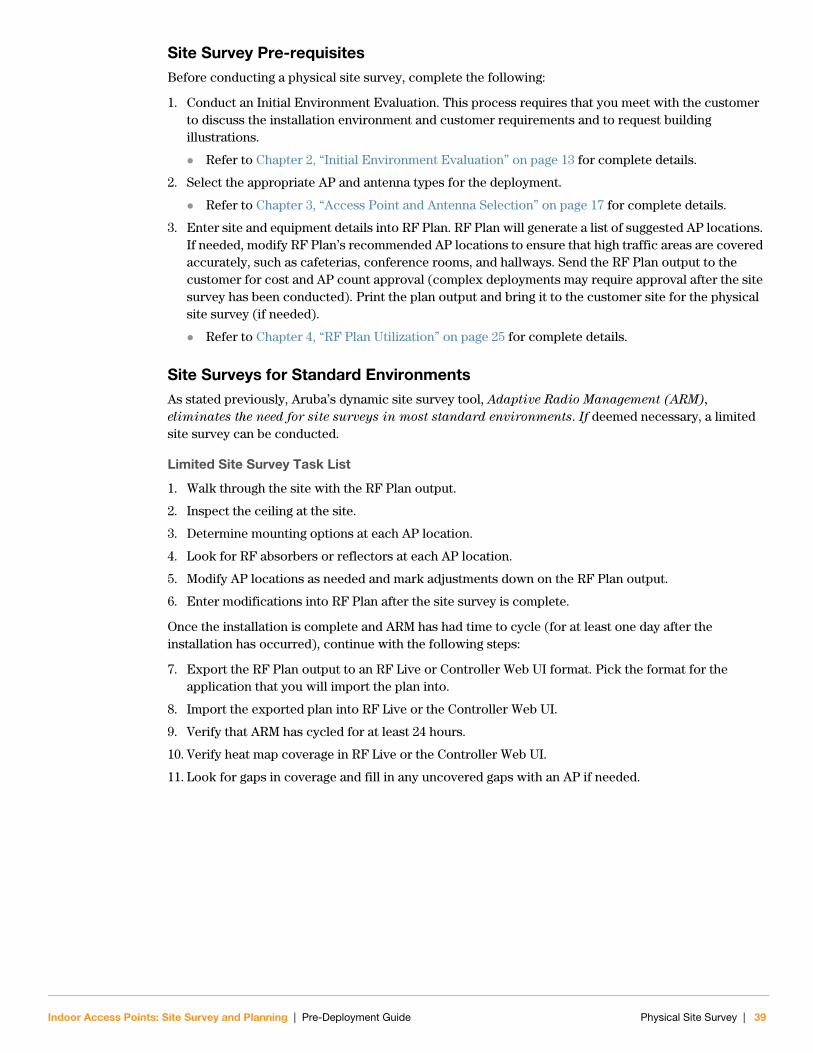
Site Survey Pre-requisitesBefore conducting a physical site survey, complete the following:
1. Conduct an Initial Environment Evaluation. This process requires that you meet with the customer to discuss the installation environment and customer requirements and to request building illustrations.
Refer to Chapter 2, “Initial Environment Evaluation” on page 13 for complete details.
2. Select the appropriate AP and antenna types for the deployment.
Refer to Chapter 3, “Access Point and Antenna Selection” on page 17 for complete details.
3. Enter site and equipment details into RF Plan. RF Plan will generate a list of suggested AP locations. If needed, modify RF Plan’s recommended AP locations to ensure that high traffic areas are covered accurately, such as cafeterias, conference rooms, and hallways. Send the RF Plan output to the customer for cost and AP count approval (complex deployments may require approval after the site survey has been conducted). Print the plan output and bring it to the customer site for the physical site survey (if needed).
Refer to Chapter 4, “RF Plan Utilization” on page 25 for complete details.
Site Surveys for Standard EnvironmentsAs stated previously, Aruba’s dynamic site survey tool, Adaptive Radio Management (ARM),
eliminates the need for site surveys in most standard environments. If deemed necessary, a limited site survey can be conducted.
Limited Site Survey Task List
1. Walk through the site with the RF Plan output.
2. Inspect the ceiling at the site.
3. Determine mounting options at each AP location.
4. Look for RF absorbers or reflectors at each AP location.
5. Modify AP locations as needed and mark adjustments down on the RF Plan output.
6. Enter modifications into RF Plan after the site survey is complete.
Once the installation is complete and ARM has had time to cycle (for at least one day after the installation has occurred), continue with the following steps:
7. Export the RF Plan output to an RF Live or Controller Web UI format. Pick the format for the application that you will import the plan into.
8. Import the exported plan into RF Live or the Controller Web UI.
9. Verify that ARM has cycled for at least 24 hours.
10. Verify heat map coverage in RF Live or the Controller Web UI.
11. Look for gaps in coverage and fill in any uncovered gaps with an AP if needed.
Indoor Access Points: Site Survey and Planning | Pre-Deployment Guide Physical Site Survey | 39

Site Surveys for Complex EnvironmentsOn-site verification of AP location and signal coverage can be beneficial to understanding the performance that will be achieved in a complex environment.
By activating an AP within the environment, you can better understand the characteristics (coverage pattern and boundaries) of the AP type within that environment. The signal-to-noise ratio (SNR) must be equal to or greater than 20. If directional antennas will be used at the site, you must also activate the designated directional antenna type for testing purposes. For extremely complex deployments, multiple APs may be used in the test environment to mimic the deployment.
However, identifying the most challenging locations (one to three key trouble spots) at the site and performing a coverage test at these key trouble spots should be sufficient and should prove that functionality will be achieved throughout the site without doing a full site survey.
Site survey findings and plan modifications should be entered into RF Plan before deployment and before the system goes live. Send the adjusted RF Plan output to the customer for cost and AP count approval once the site survey is complete. Directional antennas must be accounted for separately from RF Plan.
For an example of a successful complex deployment, please refer to Appendix B, “Successful Complex Deployments” on page 49.
Site Survey Toolkit
The contents and requirements of a site survey toolkit will vary and are dependent on both the surveyor and the environment.
A typical toolkit for an Aruba site survey might consist of the following:
Aruba 200 or Aruba 800 Mobility Controller
If the Aruba 200 is used, power bricks for the APs and controller are required, as well as a power strip and 50 foot extension cord.
200 feet of CAT5 cables
AP(s) - desired type for the deployment
Directional antennas (if applicable) - desired type for the deployment
Tripod(s) for extending APs from the floor to ceiling to mimic the deployment location
In this scenario, the controller runs Aruba’s dynamic RF management tool (ARM) and reports back in real-time how RF is propagating and what is happening in the environment.
OR
AP(s) desired type for the deployment
Aruba 200 or Aruba 800 Mobility Controller
If the Aruba 200 is used, power bricks for the APs and controller are required, as well as a power strip and 50 foot extension cord.
Software tool used to measure how RF is propagating (Example: NetStumbler™)
Representative handheld device, such as an Intermec™ or Symbol™ scanner, that will be used in the production environment, running ping tests and if possible, running a signal strength meter.
Cognio Spectrum Expert™, Wi-Spy™, or some other RF spectrum analyzer.
40 | Physical Site Survey Indoor Access Points: Site Survey and Planning | Pre-Deployment Guide

Detailed Site Survey Task List
1. Bring your initial RF Plan output and site survey toolkit to the site.
2. Perform an initial walkthrough of the facility to identify key challenges based on required range, mounting locations restrictions, or other factors, such as absorbers, reflectors, or known interference sources.
3. Modify the plan as needed using omni-directional or directional antennas.
4. Present the coverage plan to the customer.
5. Identify the most challenging locations (ideally one, but two to three maximum) that are candidates for a demonstration/coverage test.
6. Perform a demonstration/coverage test to show functionality in those worst case locations.
Indoor Access Points: Site Survey and Planning | Pre-Deployment Guide Physical Site Survey | 41

42 | Physical Site Survey Indoor Access Points: Site Survey and Planning | Pre-Deployment Guide

Indoor Access Points: Site Survey and Planning | Pre-Deployment Guide
Appendix A
Integral, Omni-Directional Antenna Positioning
Ceiling Deployments
AP-60/61
Figure 23 AP-60/61 Integral, Omni-Directional Antenna Positioning
!CAUTION
For optimal antenna performance, the integral, omni-directional antenna must be positioned perpendicular to the floor. This prime position provides the best horizontal coverage pattern possible.
N O T E
Regardless if the AP is installed at, below, or above the level of the ceiling tiles, the integral, omni-directional antenna must be oriented perpendicular to the floor.
AP-60/61 Correct Antenna Position
Antenna shown is perpendicular to the floor.
AP-60/61 Incorrect Antenna Positions
Antennas shown are not perpendicular to the floor.
Integral, Omni-Directional Antenna Positioning | 43

AP-65
Figure 24 AP-65 Integral, Omni-Directional Antenna Positioning
AP-65 Correct Antenna Position
Antenna arms shown are perpendicular to the floor.
AP-65 Incorrect Antenna Positions
Antenna arms shown are not perpendicular to the floor.
44 | Integral, Omni-Directional Antenna Positioning Indoor Access Points: Site Survey and Planning | Pre-Deployment Guide

AP-70
Figure 25 AP-70 Integral, Omni-Directional Antenna Positioning
AP-70 Correct Antenna Position
Antenna shown is perpendicular to the floor.
AP-70 Incorrect Antenna Positions
Antennas shown are not perpendicular to the floor.
Indoor Access Points: Site Survey and Planning | Pre-Deployment Guide Integral, Omni-Directional Antenna Positioning | 45

Wall Deployments
AP-60/61
AP-60/61 Correct Antenna Position
Antenna shown is perpendicular to the floor.
AP-60/61 Incorrect Antenna Positions
Antennas shown are not perpendicular to the floor.
46 | Integral, Omni-Directional Antenna Positioning Indoor Access Points: Site Survey and Planning | Pre-Deployment Guide

AP-65
AP-65 Correct Antenna Position
Antenna arms shown are perpendicular to the floor.
AP-65 Incorrect Antenna Positions
Antenna arms shown are closed or are not perpendicular to the floor.
Indoor Access Points: Site Survey and Planning | Pre-Deployment Guide Integral, Omni-Directional Antenna Positioning | 47

AP-70
AP-70 Correct Antenna Position
Antenna shown is perpendicular to the floor.
AP-70 Incorrect Antenna Positions
The antenna on the left is perpendicular to the floor, but the antenna is in a closed position and the AP-70 hardware is blocking some of the RF signal.
The antenna on the right is not perpendicular to the floor.
48 | Integral, Omni-Directional Antenna Positioning Indoor Access Points: Site Survey and Planning | Pre-Deployment Guide

Indoor Access Points: Site Survey and Planning | Pre-Deployment Guide
Appendix B
Successful Complex Deployments
Complex Deployment Example: Bus DepotThe planning example included in this appendix covers a custom-based planning model for a complex deployment. The site required WLAN coverage for a typical office-like environment, an indoor garage/bus depot, and the outdoor area around the perimeter of the garage (see Figure 26).
Figure 26 Complex Deployment Floor Plan
During the Initial Environment Evaluation, it was determined that the site required dedicated APs providing WLAN service and dedicated security AMs for both radio bands, 2.4 and 5 GHz. These APs and AMs needed the capability of providing simultaneous coverage on both bands. The best Aruba AP choice for this type of environment was a combination of APs: the AP-65 and the AP-70. The AP-65 provided the coverage needed for the narrow office area and conference rooms. The AP-70 was chosen for the air monitors, indoor garage, and outdoor areas due to a higher gain antenna which provided the larger RF footprint required in those areas.
A capacity-based model using the AP-65 was chosen for the indoor office like environment.
A coverage-based model using the AP-70 was chosen for the indoor garage area.
A coverage-based model using the AP-70 and the AP-ANT-82 was chosen for the outdoor area.
Office Area
Conference Rooms
Outdoor
Outdoor
Outdoor
Outdoor
Indoor Garage/Bus Depot
N O T E
The AP-70s for the outdoor area were deployed on each corner of the building, were enclosed within an NEMA enclosure, and were protected by an overhang. If a site required outdoor coverage farther out from the building and if the access points’ exposure level to natural elements would be high, such as rain, wind, and lightning, one of Aruba’s outdoor AP models would be recommended. In lieu of the AP-70 within an NEMA enclosure, Aruba’s outdoor AP-80M, which does not require an NEMA enclosure, can be used in this scenario or in a similar deployment.
Successful Complex Deployments | 49
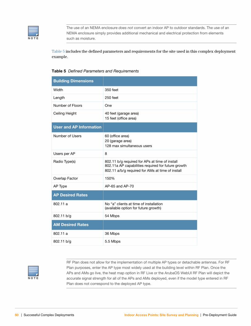
Table 5 includes the defined parameters and requirements for the site used in this complex deployment example.
N O T E
The use of an NEMA enclosure does not convert an indoor AP to outdoor standards. The use of an NEMA enclosure simply provides additional mechanical and electrical protection from elements such as moisture.
Table 5 Defined Parameters and Requirements
Building Dimensions
Width 350 feet
Length 250 feet
Number of Floors One
Ceiling Height 40 feet (garage area)15 feet (office area)
User and AP Information
Number of Users 60 (office area)20 (garage area)128 max simultaneous users
Users per AP 8
Radio Type(s) 802.11 b/g required for APs at time of install802.11a AP capabilities required for future growth802.11 a/b/g required for AMs at time of install
Overlap Factor 150%
AP Type AP-65 and AP-70
AP Desired Rates
802.11 a No “a” clients at time of installation(available option for future growth)
802.11 b/g 54 Mbps
AM Desired Rates
802.11 a 36 Mbps
802.11 b/g 5.5 Mbps
N O T E
RF Plan does not allow for the implementation of multiple AP types or detachable antennas. For RF Plan purposes, enter the AP type most widely used at the building level within RF Plan. Once the APs and AMs go live, the heat map option in RF Live or the ArubaOS WebUI RF Plan will depict the accurate signal strength for all of the APs and AMs deployed, even if the model type entered in RF Plan does not correspond to the deployed AP type.
50 | Successful Complex Deployments Indoor Access Points: Site Survey and Planning | Pre-Deployment Guide

Figure 27 depicts the actual AP and AM deployment locations for the complex site. The AP locations are represented by green AP icons on the floor plan and the AM locations are represented by yellow AM icons. The fifteen AP and five AM icons are numbered. These AP and AM numbers are called out in Table 6, which provides descriptive information for each AP and AM.
Figure 27 Complex Deployment AP and AM Placement
Table 6 Custom-Based Model for Capacity and Coverage
AP or AM Name in Figure 27Aruba AP Type
Aruba Antenna Type
Comments
AP-1, AP-3, AP-4, and AP-5 AP-65 Integral Omni-Directional Antenna
These APs support an office area using a capacity-based model.
AP-6, AP-7, AP-8 AP-65 Integral Omni-Directional Antenna
These APs are positioned within near proximity of each other to support a pair of conference rooms.
AP-2, AP-9, AP-11, and AP-13 AP-70 Integral Omni-Directional Antenna
These APs support the indoor bus depot area using a coverage-based model and are positioned within each corner of the indoor garage area. The AP-70’s integral omni-directional provides the needed coverage for the indoor area’s bus maintenance staff and onboard bus equipment, such as downloading maps to the onboard GPS system or music to MP3 players.
AP-1
AM-1AM-2
AM-3
AM-4
AM-5
AP-2
AP-3
AP-4 AP-5
AP-6AP-7AP-8
AP-9
AP-10
AP-11
AP-12
AP-13 AP-14
AP-15
Indoor Access Points: Site Survey and Planning | Pre-Deployment Guide Successful Complex Deployments | 51

Figure 28 is representative of the heat map generated in RF Live for this complex site. Note the larger RF footprint for the AP-70s versus the AP-65s.
Figure 28 Complex Deployment Coverage Pattern
AP-10, AP-12, AP-14, and AP-15 AP-70 within an NEMA enclosure
DetachableDirectional Antenna: AP-ANT-82
These APs provide outdoor support for the bus maintenance staff and bus equipment and implement the use of the AP-ANT-82 directional antenna. The AP-ANT-82 is a 90 degree sector antenna, which was chosen to provide coverage around the building. The APs are installed just outside of the garage area and on each corner of the building.
NOTE: The use of an NEMA enclosure does not convert an indoor AP to outdoor standards. The use of an NEMA enclosure simply provides additional mechanical and electrical protection from elements such as moisture.
AM-1, AM-2, AM-3, AM-4, and AM-5
AP-70 Integral Omni-Directional Antenna
These are dedicated air monitors for security purposes.
Table 6 Custom-Based Model for Capacity and Coverage
AP or AM Name in Figure 27Aruba AP Type
Aruba Antenna Type
Comments
AP-1
AM-1AM-2
AM-3
AM-4
AM-5
AP-2
AP-3
AP-4 AP-5
AP-6AP-7AP-8
AP-9
AP-10
AP-11
AP-12
AP-13 AP-14
AP-15
52 | Successful Complex Deployments Indoor Access Points: Site Survey and Planning | Pre-Deployment Guide

Indoor Access Points: Site Survey and Planning | Pre-Deployment Guide
IndexAabsorbers 38
access pointapplication requirements 18band requirements 18benefits of 18dedicated 18dual radio 18, 19indoor 19models 19scanning 19selection of 17, 18single radio 18, 19type of 19
air monitorbenefits of 18dedicated 18
AM, See also air monitor
antenna 20beamwidth 21detachable selection 24directional 20gain 21omni-directional 20pattern 21pattern plots 23positioning of 43positions, examples of 43selection of 17specifications 23understanding of 20wireless 20
AP-41 18, 19
AP-60 18, 19, 43, 46
AP-61 18, 19, 43, 46
AP-65 18, 19, 44, 47, 49, 51
AP-70 18, 19, 45, 48, 49, 51
AP-80M 49
application requirements 18
Bband requirements 18
beamwidth 21
Ccapacity model 15
ceiling deployment 15antenna positioning 43
ceiling installation 15
complex deployment 13coverage pattern 52detailed site survey 41example 49
AP and AM placement 51product selection 51
site survey 37, 40survey tool kit 40
coverage model 14
coverage patterns 35
custom model 15
customer servicetelephone support 10web site support 10
Ddeployment
capacity model 15ceiling 15complex 13coverage model 14custom 15high bandwidth 15low bandwidth 14standard 13wall 15
deployment, See also complex deployment
deployment, See also standard deployment
detachable antennas 24
detailed site survey 41
directional antenna 20
Eenvironment
assessing of 37RF absorbers 38RF interference sources 38RF reflectors 38
Index | 53

54 | In
environment, type ofcomplex 13standard 13
environmental factors 37
examplecomplex deployment 49standard deployment 26
Ffloor plan
accepted file types 25importing image into RF plan 30
Ggain 21
Hhistorical building 13
hospital 13
Iinterference sources 38
Llimited site survey 39
NNEMA enclosure 52
Oomni-directional antenna 20
ceiling deployment 43integral 43positioning of 43wall deployment 46
Pplacement of
AMs 38antennas 38APs 38
planningexample 26tool 25
planning tool 25
Rradio frequency
absorbers 38interference sources 38reflectors 38wireless coverage considerations 14
reflectors 38
RF plan 25accepted image types 25coverage patterns 35example 26importing image/floor plan 30pre-requisites 26task overview 27utilization of 26
RF, See also radio frequency
Sscanning AP 19
site planninginitial environment evaluation 13overview 11
site surveycomplex deployment 37, 40complex environment 40conducting of 38detailed site survey 41limited site survey 39overview 37pre-requisites 39product placement 38standard deployment 37, 39standard environment 39tool kit 40
spatial diversity 19
standard deployment 13example 26limited site survey 39site survey 37, 39
supporttelephone support 10web site support 10
survey, See also site survey
Ttool kit 40
Wwalk-through, See also site survey
wall deployment 15antenna positioning 46
wall installation 15
dex Indoor Access Points: Site Survey and Planning | Pre-Deployment Guide

Indoor
wireless antenna 20
wireless coverageconsiderations 14model type 14
capacity-based 15coverage-based 14custom-based 15
Access Points: Site Survey and Planning | Pre-Deployment Guide Index | 55

56 | In
dex Indoor Access Points: Site Survey and Planning | Pre-Deployment Guide