diffusion coating process for columbium base … · diffusion coating process for columbium base...
TRANSCRIPT

ML-TDR-64-71
DIFFUSION COATING PROCESS FORCOLUMBIUM BASE ALLOYS
TECHNICAL DOCUMENTARY REPORT No. MI-TDR-64-71
JUNE 1964
AIR FORCE MATERIALS LABORATORYRESEARCH AND TECHNOLOGY DIVISION
AIR FORCE SYSTEMS COMMANDWRIGHT-PATTERSON AIR FORCE BASE, OHIO
DDC
Project No. 7381, Task No. 738102 '' - - 72
;DC IRA A
(Prepared under Contract No. AF 33(616)-7896 byVought Astronautics Division, Chance Vought Corporation,
Dallas, Texas;William L. Aves, Jr., Gordon W. Bourland, Aleck B. Featherston,
Brennan A. Forcht, and Kent P. O'Kelly, authors)
S- TICES
When Government drawings, specifications, or other data are used forany purpose other than in connection with a definitely related Governmentprocurement operation, the United Stated Government thereby incurs noresponsibility nor any obligation whatsoever; and the fact that the Govern-ment may hare formulated, furnished, or in any way supplied the said draw-ings, specifications, or other data, is not to be regarded by implication orotherwise as in any manner licensing the holder or any other person orcorporation, or conveying any rights or permission to manufacture, use,or sell any patented invention that may in any way be related thereto.
Qualified requesters may obtain copies of this report from the DefenseDocumentation Center (DDC), (formerly ASTIA), Cameron Station, Bldg. 5,5010 Duke Street, Alexandria, Virginia, 22314.
This report has been released to the Office of Technical Services, U.S.Department of Commerce, Washington 25, D. C., in stock quantities forsale to the general public.
Copies of this report should not be returned to the Research and Tech-nology Division, Wright-Patterson Air Force Base, Ohio, unless returnis required by security considerations, contractual obligations, or noticeon a specific document.
500 - Jy 1964 - 162-44-907

FQOI,-mFD
This report was prepared by Chance Vaught Corp ,ration as RekortNo. 00.122 under USAF Contract No. AF 33(616)-7E96. T-nrs contractwas initiated under Pruject .5o. 7361, "Material- Apications," TaskNo. 7381.2, "Materials Preproductioa Processes.' The work -asadministered under the direction of the A? Materials Laboratory,R.search and Technologa Division, Air Torce Systezs Co.imand, Wright-Patter.son Air Force Base, Ohio, "rtJi L. 1h. Hje1m-, l/Lt, UStF, actiraas Project Engineer.
This report covers work co:ducted from Februlary 1-61 to February1962.
The authors would like to 3xpress appreciation to L. 11. HjeLI,1/Lt, L5AF, RTD Projaco Engineer, for helpful ugge3ticfn3 and guidancethroughout the program.
Mention should also be made of Chance Vought personrel who havecontributed, in particular, Mr. Glen Ecord for preparation of meta!l-ographic apecirmens and interpretation of photomicrographs; Yr. John T.Lynch for his analytical Jork in the development of techniques utiliz-ing the Heinrich X-Ray miniature probe and X-Ray diffraction as appliedto coating study; Mr. Joseph Van Veizor and Mr. Julian Kycia forassistance in preparation of test specimens and coatings.

ABSTRACT
This program was to improve and optimize coatings for columbium alloys,protective in air to 2600*F for at least 10 hours. Process variables of twodifferent silicide base coating systems(Si-Cr-A1 and Si-Cr-B) applied by at-;o-step pack cementation process were optimized by statistical methods.Coatings were evaluated on D-31, C-103, Cb-lZr (FS-80), and FS-82 columbiumalloys.
Oxidation resistance testing included furnace testing in moving air,susta.ned load thermal cycling, propane torch and ram-jet tests. Tensilestreugth and bend properties of uncoated and coated alloys were evaluatedat room aLI elevated temperatures. An analytical evaluation of these systemswas conducted to characterize the coating components. In addition, oxidationtests in the range 10000 to 20000F were conducted to determine "di-silicidepest" effects on the two systems. The Si-Cr-B system was unaffected by thisphenomenon.
A simulated leading edge assembly containing welds and rivets in exposed1 ocations was fabricated, coated with the Si-Cr-B system, and tested in glidere-entry conditions. There was no visible detrimental effect on the coatingas a result of this test.
This technicil dcc=rI-ntzrj report has been reviewed and is approved.
VW.-P. CONRA1R)Y, Chief aMaterials Engineering BranchMaterials Applicetions Division

TABLE OF CONTETS
IJIF ODUCTI ON ............ . ........ ...... 1
SCOPE OF PROGRAM ................................. 2
LITERATURE SURVEY ............................... 5
GENERAL COTIM PROCEDURE .. .... o ........ o ....... 9
TEST PROCEIJRES .. ..................... e.. . 10
RESULTS
A. Phase I ............... ........... 13
B . Phase II ...................... .. 18
C. Statistical Analysis ..... 0000 25
D. Analytical Evaluation .................. 30
E. Phase III .................. ........ . 32
CONCLUSIONS ........................ 37
WERENCES ................. o..................... 111
iT

LISTI CF FIGUTS
Page
1. Test Specimens Used in Pheses I and I1All Specimens 0.0201 Nominal T1hickness 68
2. Test Specimens Used in Phase III
All Specimens 0.020" Noinnal Thickness 69
3- Thrtially Loaded Retort 71
4. loading Retort in Furnace 72
5. Controlled Air Flow Furnace 73
6. Transition Temperature Bend Jig 74
7. Uncoated Cb-l Zr (250x) 75
8. Uncoeted D-31 (2c0x) 76
9. Uncoated C-103 (250x) 77
10. Lncoated C-103 Showing -n Inclusion in the BaseI:etLA (2f5x) 78
11. Cb-i Zr Coated wit h Si-Cr-Al Deposited in T'oCycles, 190c0 F for 16 Hours Each Gyclc (2fOx) 79
12. Cb-1 Zr Coated wit'. Si-Cr-B Lposited in ".oCycles, 10CO°F for 16 Hours Lech Cycle (250x) 79
13. D-31 Coated with Si-Cr-Al Deposited in TwoCycles, 19000F for 1l /Uours Lech Cycle (250x) C0
14. C-IC3 Coated for Si-Cr-A Leiosite, in TwoCycles, 1900 0F for 16 HourR Each Cycle (2s0x) 60
Ir. Cb-l Zr Coated with Si Only, et Verio ls-e jerbtures for 26 Hours 81
16. Lffcct of Retort Seal lermeebility on Depositionof the Cr-B on tl.e Si]icide Coating 82
V

LIST OF FIGURES (cont.)
Page
17. Cr-A! Second Coats on Silicide Coatings Depositedat 1700"F on Cb-1 Zr (25ox) 83
18. Cr-A] Second Coats on Silicide Coatings Depositedat 1900*F on Cb-1 Zr (25Ox) 84
19. Cr-A1 Second Coats on Silicide Coatings Depositedat 2100F on Cb-i Zr (25ox) 85
20. Oxidation Resistance Specimen Coated with theSi-CrAl System after 10 Hour Exposure at2600"F (25Ox) 86
21. Photomicrographs of Cr-A1 Second Coats on SilicideCoatings Deposited at 2300"F on Cb-i Zr (250x) 87
22. Cb-l Zr Coated with Si at 1900OF for 16 Hours,Followed by Cr-B Coating for Indicated Temperaturesand Times 88
23. Oxidation Resistance Test Specimens at VarioisStages of Preparation and Testing 89
24. Photomicrographs Showing Cb-i Zr Specimens Coatedwith Silicide at 2100"F for 16 Hours and Cr-Al at2200OF for 16 Hours, Tested for Oxidation Resistanceat 2600"F (250x) 90
25. Photomicrographs Showing Cb-l Zr Coated with Silicideat 2100OF for 16 Hours and Cr-B at 2200OF for16 Hours, Tested for Oxidation Resistance at 2600"F 91(250x)
26. -Lipresentation of Results of Analytical Evaluationof Cb-l Zr Coated with Silicide First Coat 0aly 92
27. Representation of Analytical Evaluation of Cb-l ZrAlloy Coated with the Si-Cr-Al System 93
28. Representation of Analytical Evaluation of Cb-l ZrAlloy Coated with the Si -Cr-B System 94
vi
LIST OF FIGURES (cont.)
Page
29. Representation of Analytical Evaluation of C-103Alloy Coated with the Si-Cr-B System 95
30. Representation of Analytical Evaluation of D-31Coated with the Si-Cr-B System 96
31. Photograph Showing Welded FS-82 Alloy and RivetedD-31 Alloy Specimens Coated with the Si-Cr-BSys tem for Oxidation Tests 97
32. Photograph Showing Lap Weld and Resistance SpotWeld Specimens after Exposure for One Hour at 2500'F 98
33. Photograph Showing Cb-l Zr Alloy Lap Shear and
Fatigue Specimens Coated with the Si-Cr-B System 99
34. Drawings of Simulated Leading Edge Assembly 100
35. Welded Components of Simulated Leading Edge Assembly 101
36. Photographs Showing Components Parts and Sequencec f Buildup of the Simulated Leading Edge Assembly 102
37. Photographs Showing the Completed Simulated LeadingEdge Assembly 103
38. Typical Re-entry Conditions for Leading EdgeSurfaces of Glide Vehicle 104
39. Test Temperatures for Hot Surface of SimulatedLeading Edge Assembly During Propane Torch Test 105
40. Photograph Showing Top Surface of the SimulatedLeading Edge Assembly after the Propane Torch Test 106
41. Photograph Showing the Bottom Side of the SimulatedLeading Edge Assembly after the Propane Torch Test 107
42. Test Conditions for Simulated Leading Edge AssemblyDuring Ram Jet Test 108
vii
LIST OF FIGUES (cont.)
Page
43. Photograph Showing the Simulated leading EdgeAssembly Mo&mted for Test in the Ram Jet Facility 109
44. hotographs Showing the Broken Portion of theSimulated Leading Edge Assembly 110
viii

LIST OF TALES
Page
i. Anal1.sis of Alloys Received for Coating 40
2. Strength of Representative Columbi= Alloys 42
3. Ronm Temperature Strength of 0.020" Coated andUncoated Columbium Alloys 43
4. Phase I Oxidation Resistance Tests on CoatedCb-l Zr Sfecimens 44
5. Phase I Oxilation Resistance Tests on CoatedSpecimens Before Optimization of Coating Systems 45
6. Tensile Strength of 0.020" Thick CoatedColumibium Alloys at Various Temperatures 46
7. Static Load Tests at 2500"F on Coated ColumbiumAlloy Specimens 47
8. Load Cycle Tests on Coated Columbium AlloyTensile Specimens 48
9. Results of Bend Tests on Coated 0.020" Specimensof Cb-i Zr, D-31, and C-103 49
10. Effect of Variation of Retort Seal Permeability andCoating Deposition Temperature on Coat Thicknessand Oxidation Resistance for Cb-i Zr SpecimensCoated with the Si-Cr-Al System 52
11. Effect of Variations of Retort Seal Permeability andCoating Deposition Temperature on Coating Thicknessand Oxidation Resistance for Cb-l Zr SpecimensCoated with the Si-Cr-B System 53
12. Effect of Variation of Cr-Al Second Coat DepositionTemperature and-Time on Coating Thick;,ess andOxidation Resistance of Cb-l Zr Specimens Coatedwith the Si-Cr-Al System (Silicide First CoatDeposited at 1700"F for 16 Hours) 54
13. Effect of Variation of Cr-Al Second Coat DepositionTemperature and Time on Coating Thickness andOxidation Resistance of Cb-1 Zr Specimens Coatedwith the Si-Cr-A1 System (Silicide First CoatDeposited at 1900OF for 16 Hours) 55
ix

IST OF 2TABLa (cont.)
Page
1r Effect of Variation of Cr-Al S-zond Coat Dezosition
Temperature and Tice on Coating MWfc ni ss andOxidation Resistance of Gb-1 Zr SDecimens Coatedwith the Si-Cr-A]- System (Silicide First CoatDeosited at 2!O0"F for !6 Hours) 56
15. Effect of Variatin of Cr-Al Second Coat Deosition
Te=per_ature and Time on Coating Thi6ess andOxidation Resistance of Cb-1 Zr Specimens Coatedwith tbe Si-Cr-.Al System (Si-icide First CoatDeposi" ed at 2300"F for 16 Hours) 57
16. Effect of Variation of Cr-B Zcz_'d Coat DepositionTerperature and Time on Coating Thickness andOxidation Resistance of Cb-i Zr Specirens Coatedwith the Si-Cr-B System (Silicide First CoatDeposited at 1900"F for 16 Hours) 58
17. Effect of Variation of Cr-B Second Coat DeositionTenrerature and Time on Coating Thickness andOxidation Resistance of Co-1 Zr SpDecimens Coatedwith the Si-Cr-B System (Silicide First CoatDeDosited at 21000F for 16 Hours) 59
18. Effect of Variation of Silicide First Coat DepositionTemerature and Time on Coating Thickness andOxidation Resistance of Co-i Zr Specimens Coatedwith the Si-Cr-Al System (Cr-Al Second CoatDeposited at 2200"F for 16 Hours) 60
19. Effect of Variation of Silicide First Coat DepositionTemperature and Time on Coating Thickness andOxidation Resistance of Cb-1 Zr Specimens Coatedwith the Si-Cr-B System (Cr-B Second Coat Depositedat 2200"F for 16 Hours) 61
20. Effect of Pack Particle Size and Pack DensityVariations on Coating Thickness and OxidationResistance of Gb-i Zr Specimens Coated with theSi-Cr-Al System. (Silicide First Coat at 2100OFfor 16 Hours, Cr-Al at 2200*F for 16 Hours) 62
x

Page
21. Effect of Variation of Halide Content in RetortPack Idx on Coating Mhickness and OxidationResistance of Cb-i Zr Specimens Coated with theSi-Cr-Al System (Silicide First Coat Depositedat 2100OF for 16 Hours, Cr-AI Second Coat DeDositedat 2200"F for 16 Hours) 63
22. Results of Phase iII ,idation Tests at 2600"F forDetermination of Reliability and Reproducibility ofthe Optimized Coating System 64
23. Results of Ln; Temperature Oxidation Tests onOtimized Coating Systems 65
24. Results of Oxidation Bend Tests on OptimizedCoating Systems 66
25. lap Shear Strength at 2200'F of Riveted SpecimensPrepared by Three Methods 67
xi
'nrr- TION
This report rmers the accomplishents in a program for the developntmd optimizatlo:, of a diffusion coating process for columbium base alloys forigh teaperature oxidation protection. In particular, this work was directedtatard the improvemnt of reliability and reproducibility of a pack cementa-tion process for diffusion coating of columbum sheet material.
7he requiremnt for this progra stemed from Air Force recognizationthat advanced technology will require completely reliable coated refractoryalleys for structural and beat abield applications at high temperatures.Pack cementation diffusion coatings to protect the base metal from oxidationat temperatures to 26OXF are a mans of satisfying this requiremt,
Although a nuir of cotIngs for refractory metals have been developedusing the pack cementation process, they have usually been realized through"trial and errora techniques without a thorough investigation of the manyvariables. This progrm has been an integrated sequence of study, develop-sent, and testing to acconplish the optimization of the coating system Athe required processing techniques to provide columbium alloys with oxidationresistance to temperatures as high as 260OF.
Manuscript released by authors Nove ber 1962 for publication as anRTD Technical Documentary Report

nWLOWTION
This report cnmers the accimplstments in a program for the develop-wntmd optiuiatio:' of a diffusion coating process for columbium base alloys forAgh te-perature oxidation protection. In particular, this work was directedLward the iuprovemnt of reliability and reproducibi~it of a pack ceoenta-Lion process for diffusion coating of colbium sheet material.
The requirewnt for this program steied from Air Force recognizationthat advanced technology will zequire completely reliable coated refractory3llays for structural and heat &Ield aplications at high temperatures.Pack centation diffusion coatings to protect the base metal from oxidationit temperatures to 2600OF are a mans of satisfying this requirement,
Although a nur of cotIngs for refractory metals have been developeduLing the pack cementation process, they have usually been realized through*tial and erorO techniques without a thorough investigation of the manyvariables. This program has been an integrated sequence of study, develop-went, and testing to acconplish the optinzation of the coating system andthe required processing techniques to provide coluwbiu alloys with oxidatioresistace to teuperatures as high as 2600oF.
Manuscript released by authors Woveber 19(2 for publication as anRTD Technical Documentary Report
1

SCOPE OF PROGRL
The purpose of the program was to extend the development of pack cementa-ticn or "diffusion coatings" for columbium base sheet alloys to the point ofcoating cpti.rIzation, reliability, and reproducibility required for Air Forceu,- '
Phase I of the prograr included a survey of available literature and areview of process and material variables with respect to their effect on coat-ing integrity and oxidation resistance. The analysis of available data wasfocused on requirements for severe service to 26000F.
The more promising systens developed by Vcught, modified by informationgained in the foregoing survey, were then evaluated in preliminary testsdesigned to give the following ir formation:
1. Comparable life2. Coating ductility3. Thermal shock resistance4. Base metal characteristics5. Base and coating thicknesses6. Adhesion7. Coating microstructure8. Change in strength due to coating9. Emissivity
10. Melting points
The tpsts in Phase I were conducted or. three 0.020" thick columbiumallcys, Wah Chang Cb-! Zr, Wah Chang C-103, and duPont D-31. The chemicalaraly~is of these alloys is given in Table I. The tests included the follow-ing:
1. Oxidation resistance of specimens coated with ten promisingcoatings.
2. Tensile tests at roor, temperature on coated ard uncoatedspecimens.
3. Tensile %,ests at 2500°F on coated specimens.4. Thermal cycle tests on coated specimens under sustained load.5. Bend tests on coated and uncoated specimens at room temperature
and -lO0F.6. Metallographic examination.
On the basis of the above tests, two coatings (Si-Cr-Al and Si-Cr-B) wereselected for further optimizaticn.
Phase II consisted of evaluation of process variables involved in pro-duci-,g the two coatings. A single alloy, Cb-l Zr, was used to establish thee~.Lect of each variable on the finished coating and substrate. The variablesevaluated for optirmzation were the following:
2

1. Coating deposition temperature2. Coating deposition time3. Retort seal permeability4. Pack density5. Pack mix particle size6. Pack ccmosition
The effect of these variables on deposited coatings was evaluated bymeans of oxidation tests at 2600'F in moving air, and by oxidation tests at2000"Y on coated specimens which were elongated by bending. eta3lopphicexamination was made of base metal, interfaces, and ctmlete coating.
In order to more fully characterize the coatings produced during thePhase II evaluation, a coating composition study ws conducted by combinedX-ray diffraction, chemical analysis, and metallographic techniques. Theresults of these studies are given in this report.
Work in Phase III was divided into three parts as follows: (1) deter-mination of process reliability and reproducibility by coating and testingthree identical sets of specimens, (2) selection of the best techniques forcoating complex multi-component assemblies, and (3) delivery of coated testspecimens and test assembly to ASD.
In order to determine process reliability and reproducibility, threeidentical sets of test specimens were coated and tested as shown below:
Alloy Coating System Test
D-31 Si-Cr-Al 3 Oxidations 2600'12 Bend elongations
D-31 Si-Cr-B 3 Oxidations 2600"?2 Bend elongations
C-103 Si-Cr-BI 3 Oxidations 2600"?2 Bend elongations
C-103 Si-Cr-B 3 Oxidations 2600"?2 Bend elongations
Cb-i Zr Si-Cr-Al 3 Oxidations 2600"?2 Bend elongations
Cb-l Zr Si-Cr-B 3 Oxidations 2600"?2 Bend elongations
Techniques for coating complex multi-component assemblies were evaluatedby preparation and testing of representative specimens fabricated in the formof bolts, rivets, skin sections, welds and structural stiffeners and theirsubsequent assemblies. Coatings were deposited on riveted specimens which werefabricated by the following methods: (1) assembly after coating with a subsequent
3
final coat, (2) complete asserbly prior to coating, (3) coating before sub-assembly, then final assembly followed by a subsequent final coating.
Delivery of ccated test specimens and test assembly to ASD included 24coated specimens for additional tests.

LITATUPY, SURVEY
A literature stowsy was conducted at the start of the progran todetermine oxidation characteristics and mechanical propertieu of cclumbt.m,alloys, as wel as the state-of-the-art of coatirg for oxdattion protection.
Oxidation of bare columbitw proceeds in two wayst (1) reaction withthe metal to fon the oxide, and (2) contsmiratlon of the rur.Cace of the uni-reacted metal to form a solid solutionof oxygen and nitrogen in the metal.Such contamination of the metal with oxygen results in surface 'and sub-ourfaceembrittlment or hardening, Ref. 1.
A number of factors other than time and temperature affect the oxtdaticnof a met4llic or inter-metellc siwface. Among these factors are the conditionof the surface and the surface ma of the metal, composition and pressure ofthe gas, orientation and structive of the metal-oxide crystals formmd, and theratio of the volums of the metal-oxides and the underlying metal.
The rate of oxidation as well as some of the physical properties pf theformed metal-oxide are .determined by the orientation of the grains of th.metal-oxide crystals formdj, Ref. 2. The ratio of the specific volume of theoxide to that of the metal appears to be related to the structure and pro-tective effect of the mtal aEde. For exampls if the ratio ef specficvolumes is very 'small, the structure of the oxide is generally porousp crumblyand unsuitable for oAdation protection.
A review of available literature on the effects of various. eonents onoxidation resistance of colurbiuI revealed the following:
I. ~ 1o2ybdentg additions as an alloying agent in columbiumimproves its ixdiIlcn bohavior imtiL the solubility, of molybdenum in theoxide scale is exceededj above 7. atmic per cent of molybdenums at whichpoint cataatropic oxidation occurs, Refs 3.
2. Vanadium.-- Vanadiu provides sam protection, as does molybdenum,up to 12,5 at.M per cent vanadium in the columbitm s, rface coatingp Ref. 3*.
3. Titanium.- Twenty and higher atomic percent of titanur. consider-ably improve tieoxtdston resLstarce of columbium through formation ofdouble oxides (Cb2 05 TiO2 and 3Cb 2O5 'i02 ). ThIs element effectively "getters"the iruiard-dLffus ng cxygen and precipitates oxides to form an internal scale,Ref. 3 and 1.
14. Zirconitm.-- Zirconium offer. relatively poor oxldaUtn ro.sirtaneeat concenltrattzrs itlcv 50 &toT.c per cent. Above 5.0 stomic per certzirconi In colu'biw, in prove the oxidation resistance by the Zcrrti..n ofa complex oxiee scale Cb2Oc ZrCZ, Ref. 3.
Best Available Copy

5. Chromium.-- It is believed that the presence of Cr2 O2 as a secondoxide combines with the Cb2 05 to form a more refractory oxidatlon resistantscale, Ref. 3.
6. Aluminum.-- Aluminum increases the oxidation resistance of columbiumin a marner sirilar to titanium. When added along with chromium it effectivelyimproves the resistance to inward diffusing oxygen.
7. Silicon.- Silicon substantially increases the oxidation resistanceof columbiiu---Ioys through the formation of columbium silicide which on con-tact with high temperature oidaticn forms a protective coating of SiO2 .
Alloying of columbium has resulted in oxidation resistance approximately50 times better than unalloyed columbium. However, even the most oxidationresistant alloy reported would require some form of protective coating forprolonged elevated temperature applications in oxidizing environments, Ref. 1.
Columbium alloys commercially available in sheet form were found to lelirited because of rolling and fabrication difficulties. None of the sheetmaterials available were found which fully satisfied the requirements offabricability, oxidation resistance, and high temperaturF strength. Dataavailable from the literature on typical commercial alloys are shown in Table2, Ref. 4.
Considering the requirements a coating for protecting columbium mustmeet, careful selection of coating materials capable of withstanding re-entryconditicns is mandatory. For long duration oxidation resistance, coatingsformulated around inter-metallics which form protective oxide films uponexposure to high temperature oxiaation warrant the most attention. Theslicides and such elements as Cr, Al, Ti. etc. form protective metal oxidefilms upon exposure, Ref. 5.
Methods which have been used in attempts to develop satisfactory coat-
ings for columbium have included the following:
Elec tro-Deposition CoatingsHigh Temperature Sprayed CoatingsDip CoatingsClad CoatingsVapor Deposition CoatingsPack Cementation Coatings
1. Electro-Deposition Coatings.-- Electroplated coatings on columbiumhave showr a tendency to poor adhesion, peeling, and/or formation of brittleinter-metallics, Ref. 5. Platings of chromium, cnpper, iron, gold, nickel,and platinum have been made on collumbium, Ref. 6 and 7.
Work by General Electric indicated that Fansteel 82 could be pro-tected by a 2 mil chromim coating for one hour at 25C0OF, however, theplating was very brittle after oxidation testing, Ref. 8. None of theseelectrc~lated coatings offered a satisfactory combination of oxidation rtsist-ance and base metal strength characteristics, Ref. 6 and 8.
6

In general, electroplated coatings are li-ited in application bythe "throwing power" of the electroplating solutions and the ingenuity usedin racking and placing anodes. It is difficult to provide essential coatingencapsulation on many shapes and for this reason this method - applicationis not considered a versatile approach.
Coatings are being successfully applied to refractory metals by theuse of electrophore-sis, Ref. 9, 10 and 11. They are principally limited atpresent to small components. The main advantages of using an electrophoresistechnique are its excellent throwing power, and the fact that oxidation re-sistant non-,onductive materials can be readil applied to the substrate.
2. High Temperature Sprayed Coatings.-- Literature reveals that morework has been repored or. spray coatings for oxidation protection than anyother method. Most of Lhe materials used in these evaluations were originallydeveloped for protection of molybdenum. A composition of chromium-34 weight% sili.ccn-20 weight % aluminum withstood six hours at 25000F. Reproducibilitywas not good since later tests were unable to withstand over two hours atthis te.2v .. rature, Ref. 12. A duplex sprayed coating consisting of a 4 milcoating of a proprietary material overlaid with a 4 mil coating of a modifiedmolybdenum disilicide is reported to be oxidation resistant to 27000F, Ref. 13.
A wide variety of flame sprayed coatings, representative o sprayedcoatings, have been developed by Vought, Ref. lh, 15, 16, 17, and 18.Although they are not alone suitable as oxidation resistant coatings theyprovide thermal barriers for specific conditions.
For purposes of protecting thin material or large skins this methodhas the following limitations:
Not adaptable to thin sheet edgesLimited to simple shapesLocalized heating may cause distortion and warpingExcessive weight required because of marginal porosity
3. Dip Coatings.- Considerable initial success has been obtained byhot dipped coatings, particularly when they are given a supplementarydiffusion treatment. Zinc has been applied to columbium by a hot dip anddiffusion technique to provide an oxidation resistant coating, Ref. 19. Inits simplest form, this new coating consists of layers of inter-metalliczinc-columbium compounds on the surface of the columbium. I!e upper limitof this coating for sustained use appears to be 2050OF at which point thecolumblin-zinc nter-metallic compound has an excessive vapor pressure whichtends to rupture the coating, Ref. 20 and 27.
Dipping of columbium and coated cclimbium in molten aluminum haseffectively improved the oxidation resistance of columbium at temperaturesof 25O00F for short time periods, Ref. 15. This property probably resultsfro, the inter-diffusion of aluminum into the columbium surface forming analloy which on oxidation yields a protective A1203 type scale.

Numerous aluminum alloy ccabtitiom containing fro 2-15 weight Isilicon and from 6-15 weight 6 chrcoum have been applied to colubium by hotdipping. These have been evaluated by General Electrlc, Ref. 21. Thealu'iimn-lO weight $ chromium-2 weight f silicon alloy was the most effective,and is reported to have prmected Fansteel 82 for more than tv hours at25OOvF, Ref. 5 and 22.
A coating of aluminm-li vtight 6 silicon applied by a slurry dippingtechnique and post-baking at 2000"F in argon is reported to prevent oxidationof the substrate for two hours at 2500OF with no visible oxidation, Ref. Ai.Coatings have a:zo been successfully applied to columbium by use of variousceramic frit ccopositions. These coatings appear to be subject to limitationsboth during processing and by their inability to protect substrate edges andcorners, Ref. 23.
4. Clad Coatings.--Clad coatings of thin stainless steel have beenmade on columbium, Ref. 24. In general, no successful colmbium-base cladmaterials suitable as a structural component fer high temperature use L2 anoxidizing environent have been developed, Ref. 3 and 5. It should also benoted that this protection method suffers from the izbrent difficulty ofprtecting edges and recesses, Ref. 5.
5- Vapor Deposition Coatings.--Vapor deposited coatings of silicon oncolumbium are reported by Fansteel Corporation to have given oxidation prote..tion for 10 hours at 18OF, Ref. 25. Coatings of nitrides, carbides, boridesand silicides have also been deposited on pure columbium by vapor deposition.The oxidation resistance characteristics of these coatings on columbiumappears to be good to approximately 2000F, although no specific tests werenoted, Ref. 26.
Thompson-Ramo-Wooldridge has recently completed a systematic investi-gation on the effects of process variables on their (Cr-Ti)-Si coating onunalloyed columbium, D-31 alloy, and F-48 alloy. They found for their processthe optimum coating consisted of a Cr-.O Ti layer about 1 mril thick (appliedby vacuum distillation at 2550F) overlaid with about . Mil of silicon(applied by vacuum distillntion at 220067). Cdlumbiu, D-31, and F-48 wereprotected in cyclic oxidation at 200F for 12, 24 and 20 hours, respectively.The coating life decreased with increasing temperature and at 2800'F, thecoating protected D-31 for one hour. Coatings of aluminum and of aluminummodifications of Cr-Ti-Si were also under evaluation and were protective toD-31 in cyclic oxidation at 2300OF and 2500F., Ref. 27 and 28.
6. Pack Cementation Coatings .-- The pack cementation process consistsof basically two steps (1) deposition, and (2) diffusion vhich involves re-duction, ion exchange, the formation of solid solutions and/or intermetalliccompounds. The two steps may be coLucted simultaneously during processing,or the diffusion cycle may be introduced as a separate step.
Diffusion coatings applied by use of the pack cementation processappear to provide the most promise of meeting the requirements of a satis-factory coating for protection against high temperature oxidation, Ref. 19,20, 29 and 30.
8

(ZIEAL COLctynr-3 PRCDR
Specimen blanks were sheared from sheet stock to the desirea size andmachined or hand finished to meet the desired requir-ments. All edges andcorners were rounded to a scooth, conti'nuous radius. Seciren sizes anddimensions used in the program are shown in Figures I a-- 2.
The specimens were cleaned, air dried, and oven heated innediatelYprior to loading the retort. All specimens, after cleaning, were handledwith clean lint-free gloves or clean instruments.
The oack material components were carefully weighed and mixed in asuitable laboratory blender. The blender was allowed to operate for aminimum of one hour to insure a uniform blend of the pack materials.
The clean, dry specimens were placed in a retort half filled with thepack material for the initial silicide coating, Figure 3. Additionalpack material was used to fill the retort. The cover was placed on theretort, and the seal filled with sand or other sealing material.
The loaded retort was then placed in a furnace capable of maintain,-ing ±25 F temperature control in the range from 1700F to 2300 F, Figure 4.After the retort was in the furnace for the desired period of time, it wasremoved and allowd to cool in air. When the retort had cooled toapproximately 140 F, it was unloaded. The specimens were washed, dried,and held for subsequent coating or evaluation.
The second coating was applied in a retort in the similar manner asthe initial silicide coat.
9

M7 FROC ED
1. Oxidation Resistaene Tests.-- One off t: prira-r considerations inthis nrora w the ebilit gf a coeting to protect co!=biu-n and coluzh='*allays from oxidation at 2600 . Oxidation resistance afforded by -the coating-.-as determi--i1 in t _is u-o--a n o the basis of visual and metallographicinspection and weigt variations.
In order to insure ooxcidizing conditions, coated specimens wereex-Dosed in a laboratory furnace in -ahich air, or en oyy gen-nitrogen mixtu,was la lo-ed to flow over the test soecimens at a controlled flow rate,Figure 5. his fl!.- rate v-ss controlled to allow a linear fl(; rate of onefoot per second over the specimens during test, or a complete change of airevery three seconds.
Measurement of specimen temperature during exposure -as made witha Leeds and Iiorthrop Optical Pyro-meter Catalog to. 8622. Temperature controlwas maintained -r;th a Honeywell Brown Pyr-O-Vane controller capable of con-trolling to 3090 F with a platinum-platinUm !3 rhodium thermocouple mountedin the furnace hot zone.
Unless otherwise noted, specimens were run and tested in duplicate.The average exposure to failure is reported in the average of the exposuretime for the two specimens. Coated specimens were weighed before and aftereach one hour exposure in the furnace. The specimens were carefully examinedafter each exposure for evidence of oxidation and coating failure.
2. Room and Elevated Temperature Tensile Strength.-- Room temperaturetensile strength tests on coated and uncoated specimens were conducted ontensile specimens prepared as shown in Figure 1. Tensile tests were con-ducted in accordance with ASIX. Specification E-8-57T "Tentative M.ethods ofTension Testing of Metallic Materials". Tests were conducted on a BaldwinUniversal Tster.
Elevated temperature tensile tests on coated specimens were alsoconducted in accordance with the ASTM specification. The coated specimenswere heated in air to the desired temperature by quartz lamp radiantheaters while the specimens were mounted in the Baldwin tester. Temperatureof the specimens during test was monitored by use of platinum-platinum 13%rhodium thermocouples mounted on the specimen. The specimens were heatedto the desired temperature End allowed to stabilize for five minutes beforebeing loaded in test.
3. Load Cycle Test.-- This test was designed to determine the effectof static loads on coated specimens which are alternately heated and cooled.It was perforred by placing a coated specimen under a static load andheating in air by quartz lamp radiant heaters. The stress level wasdetermined by the mechanical properties of the coated alloy, as determinedby the elevated temperature tensile tests described above.
2 o The specimens were t~errally cycled by heating in five minutes to
2500 F, holding for five minutes at that temperature, and coolin,, to roo>
10

terpDera-ure in five inutes. The therrial c:,cle was controlled by a Researchincorporated inition power controller coupled with an automatic time-temmperatture rogramer. Each specimen was cycled until failure. Observations-ere _de after each cycle for visible oxidation or changes in the coating.
4. Transition Temperature Bend Test.-- It was desirable to determinethe effect of :-he cating and coating process on the ductility of thin sheet.A ben d test aoeared to be the best method for determining this characteristicsince it would proviide data on the effects of tension and compression. Inaddition it provides an indication of the influence of the coating on the basemetal ductile-brittle transition temperature.
The more co=.on bend test fixtures were unsatisfactory because theyinvolved bendin a specimen over a mandrel. Such a mandrel obscures visualinsDection of the compression side of the test specimen during the test. Themandrel would also effect a coating because of high localized bearingloads.
A test fixture was designed and constructed which was capable ofbending a 1" x 4" specimen through 1800 with a decrease in bend radius,without the use of a mandrel. This radius reduces to a 0.5 inch over a1-3/4" bend length when the specimen is bent through 1800. A diagram of thetest fixture is shown in Figure 6.
The test was performed by placing the specimen in the end clamps,and bending the specimen over a decreasing radius while at t e test tem-perature. Tests were conducted at room temperature and -100 F. The specimenwas observed on both the tension and the compression sides at various bendradii during the test. Visual observations were made on the effects ofbending on both coating and base metal.
5. Oxidation Resistance - Bend Tests.-- Tests were conducted todetermine oxidation resistance of ,oated specimens after various amounts ofcoating elongatioB. These tests wure performed by exposing l" x 4" coatedspecimens at 2000 F after elongating the coating various controlled amounts.
The same bend fixture was used for this test as was used for theTransition Temperature Bend Tests as described above. However, theelongation of the coating on the tension side of the 1" x 4" specimen wascalculated as a function of bend radius.
Each coated specimen was elongated in increments of 0.25% or 0.50%in the bend test fixture. After each coating elongation the specimen wasremoved from the fixture and exposed to 2000&F in slowly moving air for onehour. The specimen was allowed to cool to room temperature and carefullyexamined for oxidation or coating damage. If there was no indication offailure the specimen was elongated again and re-exposed at 20000F. Thisprocedure of elongation and temperature exposure was continued until thespecimen either exhibited coating failure or the specimen had been bentthrough the full 1800F.
6. X-Ray Diffraction and Emission Studies.-- Studies of coatingcomposition were conducted in conjunction with the Phase II evaluation ofprocess variables. These studies were conducted on specimens coated with
llI
the Si-Cr-Al and Si-Cr-B systems. The work was performed on a GeneralElectric XRD-5 Diffractomer using a Cobalt tube set at 6 milliamps and 50 KVP.A Fe2 0S filter was used at the detector.
.. For x-ray diffraction studies coated specimens were placed in metal-lographic mounts with the coated surface parallel to the face of the mount.Specimens of 1" x 1/2" were used because of the large interception area of thex-ray beam. The mounted specimens were placed in the diffraction holder anda diffraction pattern was obtained at an x-ray take-off angle of 2 and a timeconstant of 4.0 seconds* The recorder scale was set for 500, 1000, or 2000counts per second full-scale linear presgntation as required. Angular measure-ments, 20, were made from 60 through 17.
After the surface diffraction pattern was obtained, specimens wereremoved from the diffraction holder and approximately 1/2 mil of coatingthickness was removed by polishing the surface. The specimen was then re-placed in the holder and another diffraction pattern was obtained using theabove procedure. Diffraction patterns were obtained at approximately 1/2 milincrements until only the base metal diffraction pattern was observed.Photomicrographs were made of the surface after removal of each 1/2 milcoating increment.
The diffraction patterns were analyzed using the ASM-X-Ray PowderData File (1960) to identify the compounds observed at various levels withinthe coating.
The x-ray emission studies were conducted on coated specimens ofabout 1/2" x 3/4". The specimens were mounted in metallographic mounts withone end approximately 10 mils higher than the other. The specimen waslightly polished in such a manner as to lap away the coating at an angle tothe specimen surface. One end was lapped down to the base metal while theopposite end was not lapped at all. This procedure exposed each layer ofcoating to the surface.
The Spectrometer was fitted with a Heinrich Miniature Probe,manufactured by General Electric Company. The goniometer was adjusted tothe peak intensity of the element in question using a 1 mm probe. The 1 nprobe was then replaced with a 100 micron probe to gain a higher signalintensity. Using this probe, the number of counts, at 0.25 mm intervalsalone the surface, was obtained for 100 second periods. The number ofcounts obtained by this method is related to the concentration of the elementin question. Chromium and columbium distribution in the coating was determinedin this manner.
7. Metallographic Examination.-- Metallographic examination, includingphotoinicrogzmphs, werv.* made ort coated and uncoated specimens to determinethe effect of the coatings 9sI the coating process on the base material. Thenature anC thickness of the verious Interfaces, diffusion zones, and layerswithin the coating were investi.tCv durin these examinations.
12
Best Available Copy

R&ULTS
A. PHASE I
1. Examination of Uncoated Columbium Alloys.--Metallographicexamination and tensile strength tests were conducted on the threecolumbium alloys in the 'as received" condition. The certifiedanalysis of the C-l Zr, D-31, and C-1D3 alloys are shown in Table 1.
Photomicrographs of these alloys are shown in Figures 7,8, and 9. As indicated in the figures, specimens were taken fromopposite corners of each sheet of alloy and a third specimen wastaken from the geometric center. It may be observed that the Cb-lZr was received in a partially recrystallized condition, while theD-31 and C-103 were received in the fully hard cold rolled condition.
During this examination a few metal defects were noted forthe C-103 alloy. An example of a typical inclusion in the alloy isshown in Figure 10. Hkwever, the effect of such inclusions on ox-idation resistance of coated -103 was not determined because of thedifficulty of detection. The D-31 and Cb-l Zr did not appear to havesimilar inclusions or metal defects.
Tensile tests of the three alloys were conducted on uncoatedspecimens of the design shown in Figure 1. The 5" dimension of thesespecimens was transverse to the direction of rolling. Room temp-erature tensile properties are shown in Table 3. These rdsultstended to verify the finding in the metallographic examination tnatthe Cb-l Zr was in a partially recrystallized condition, while theD-31 and C-103 were in the cold rolled condition.
2. Oxidation Resistance Tests.--Oxidation resistance tests,as part of Phase I, were performed to determine the two best coatingsfor use in evaluation of the effects of process variables. Thetests were conducted by exposing coated specimens at 2300OF and 2600°Fin moving air.
In order that a nuaber of different coating systems couldbe evaluated quickly the initial tests were conducted on Cb-l Zr.Sixty 1 x 1" x 0.020" Cb-l Zr oxidation resistance specimens wereprepared for testing. These tests were conc'ucted to determine packcompositions which would deposit coatings with a melting or fusingtemperature above the 2600°F test temperature, The results of thesetests are shown in Table 4.
On the basis of these results, two of the coating systemswere chosen for further evaluation. One of the systems consisted ofa coating deposited from a pack containing 60% silicon followed bysecond coating deposited from a pack containing 35% chronium and 20%Al. This coating combination is designated as the Si-Cr-Al system
13

hereafter in this report. The other system consisted of a coatingdeposited from a sack containing 60% silicon followed by a secondcoating deposited from a pack containing 30% chronium and 30% ferro-boron. This coating cobination is designated as the Si-Cr-B systemhereafter in this report,
The oxidation resistance of the two coating systems on C-103and D-31 alloys was also determined. The results of these tests areshown in Table 5. It may be observed that the oxidation resistanceof the coatings on all three alloys are comparable, ranging from threeto five and one-half hours at 260O°F.
3. Tensile Strength of Coated Specimens.-Tensile tests of thethree alloys were conducted on coated specimens of the design shownin Figure 1. These results are shown in Table 6.
Specimens of Cb-l Zr coated with both systems were testedat room temperature to determine their effect on the alloy. Sincethis material was received in a partially recrystallized conditionany changes in strength and elongation could be ascribed to the coat-ing or coating process.
The average ultimate tensile strength of the Cb-l Zr coatedwith the Si-Cr-Al system is shown in Table 6 to be h9,200 psi. Al-though they are not shown in the table the average 0.2% yield strengthand elongation was found to be 29,800 psi and 20%, respectively, withthis coating system. The average ultimate tensile of Cb-l Zr coatedwith the Si-Cr-B was found to be 49,500 psi with an average 0.2%yield strength of 28,750 psi and elongation of 20%. By comparingstrength values shown in Tables 3 and 6 for coated and uncoatedCb-l Zr it may be seen that the coating and coating process had anegligible effect on the strength properties of this alloy.
Elevated temperatures test up to 2500°F were conducted oncoated specimens to determine a satisfactory static load for thesucceeding Load Cycle Tests. The tensile Droperties at elevatedtemperature were determined by heating the coated specimens to temp-erature in air with quartz lamps, stabilizing for five minutes, andpulling the specimens at a load rdt of 0.005" per minute untilfailure. Only a limited number of specimens were tested for tensilestrength at elevated temperature, thus the strength values shouldnot be considered exact. However, the results are generally inagreement with reported strengths of the uncoated alloys as shownin Table 4. No elongation values are shown because of rapid ox-idation, and consequent loss of specimen length, as soon as ultimatefailure occurred. However, it was evident during these tests, andduring s.cceeiint static lond tests, that the specimen elongationwas much greater than 10% before oxidation began. Ine results ofthese tests are also shown in Table 6.
h. Load Cycle Tests.-- A knowledge of the effect of sustained
14

loads on coated columbium alloys during thermal cyclinF was desiredas an indication of the high temperature oxidation protection char-acteristics of the coating. Difficulty was encountered in establish-ing the static load to be maintained during the load cycle tests.As described in Test Procedure, the sDecimens were held at a constantload during thermal cycling. Initially, a value of 60% of ultimatestrength was chosen as the static load. When this stress level wasused with coated D-31 the specimens tended to creep excessively, makingsatisfactory data unobtainable. For instance, A D-31 specimen wasplaced under a sustained load of 6500 psi (60% of 10,8O psi) forseven minutes at 25OF. The specimen elongated 38% over a 2 "length.
It was then necessary to establish a load which would notproduce excessive creep at 25000F. To determine this stress levela group of coated specimens were loaded at increasing load levelsstarting at 1000 psi and held at 2500OF for seven minutes. Theseresults, Table 7, show loads in excess of 2000 psi give appreciableelongation at 25000 F. O. the basis of these tests it was decideda load no greater than 2000 psi would be used for the Load Cycle Tests.
The Load Cycle Tests were performed at static loads of 1000and 2000 psi. Visual examination of these specimens indicated load-ing was a factor in the failures. Table 8 shows Cb-l Zr specimenstested at 2500°F under a load of 2000 psi withstood only 3 cyclesfor one specimen and 2 cycles for another specimen. The same alloytested with a 1000 psi withstood an average of 5 cycles for fourspecimens. Although no elongation measurements of failed specimenscould be made, it was apparent from the neck-down portion of thetensile specimens that significant elongation had tak.-n place. Theliterature reports that the Cb-l% Zr alloy has an ultimate strengthof 13,000 psi at 2O0°0F. An extrapolation of this value to 25000;indicates a strength level for Cb-l Zr of only a few hundred poundsper square inch. Thus, it would be expected this alloy would not beable to withstand more than a few cycles under any loading.
The number of cycles withstood by D-31 and C-103 specimensalso indicate loading had a decided effect on durability under thermalshock. The coated C-103 specimens withstood an average of 5 cyclesunder a load of 2000 psi, and an average of 13 cycles under a load of1000 psi. The D-31 specimen showed the same trend with an averageof 7 cycles under a 2000 psi load, and 15 cycles under a 1000 psiload. No major differences were evidenced by the load cycle testresults which would indicate an advantage of one of the coatings overthe other.
These tests were conducted on coatings which have since beenimproved as a result of data obtained from the Phase II work.
5. Transition Temperature Bend Tests.--Bend tests, as described
15

in Test Procedure, were performed on coated and uncoated speinensof all three alloys. These tests were conducted at room temperatureand -100 0 F.
The uncoated alloy was bent at both temperatures through1800 on a one-half inch radius with no failure.
Cb-l Zr specimens coated with the Si-Cr-B system and testedat room temperatue had very small flakes of coating pop off on thecompression side when the specimen was bent to a radius f l-l/3".When the radius was reduced to 0.8" the coating popped off along astraight line across the one-inch width cf the specimens. Furtherbending tended to produce an uneven radius and the specimen bent ata sharp angle where the metal was bare. There was no visible effecton the tension side of the bent specimen.
Three Cb-l Zr specimenn coated with the Si-Cr-B system weretested at -lO0F. One specimen failed by breaking at a bend radiusof 0.8-inch. The other two specimens failed by breaking at a bendradius of one-inch. There was no visible change in the coatingprior to failure.
Three Cb-l Zr specimens coated with the Si-Cr-Al system weretested at-room temperature. The coating on cne of the specimensflaked off along a straight line at a bend radius of 0.57", while thecoating on the second specimen formed a line at a radius of 0.5".The third specimen did not develop a bare line across the specimeneven when bent to a radius of 0.5", although there was a slightflaking off of coating when the radius was 0.57".
Three Cb-l Zr specimens coated with the Si-Cr-Al system weretested at -1000F. Two of the specimens broke when bent to a radiusof one-inch and the third ipecimen broke when bent to a radius of1.1". There was no visible effect on the coating prior to failure.
Room temperature bend test results on coated D-31 and C-103agreed closely with the results found for the coated Cb-l Zr specimens.Coating specimens of D-31 and Cb-l Zr tested at room temperatureshowed flaking of coating when the specimens were bent to a radiusbetween 0.5" and 1.0" over the 1-1/2" free length. The coatingsinvariably had an initial flaking of coating along one edge and analmost imediate flaking off of the coating in a straight line acrossthe one-inch width of the specimen. The coated C-103 specimens didnot fail when bent to a 0.5" radius at room temperature.
Coated specimens of Cb-l Zr and D-31 bent at -100OF brokecleanly into two pieces with no prior effect on the coating. TheC-103 coated specimens did not break, but exhibited a flaking off ofthe coating similar to that exhibited by the room temoerature spec-imens.
16

Results of these tests are given in Table 9.
6. Metallographic Inspection.-The effect of the unoptimizedcoating process for deposition of the Si-Cr-Al and Si-Cr-B systemson the base alloy was investigated by metallographic inspection ofcoatings on all three alloys.
A photomicrograph of Cb-l Zr coated with the Si-Cr-Al systemis shown in Figure II. The coating thickness was found to be 0.0025,with a diffusion zone approximately 0.0001" thick at the coating-base material interface. Comparison of this figure with Figure 7showed there was no significant change in recrystallization in theCb-l Zr caused by the coating process.
A photomicrograph of Cb-l Zr coated with the Si-Cr-B systemis shown in Figure 12. The coating thickness was found to be 0.002",with a diffusion zone approxiately 0.00015" thick at the coating-base metal 3nterface. As with the Si-Cr-Al system, comparison ofthis figure with Figure 7 showed there was no significant recrystall-ization in the Cb-i Zr caused by the coating process.
Similar photomicrographs for the Si-Cr-Al system depositedon D-31 and C-103 are shown in Figures 13 and 14, respectively. Thecoating on both alloys was found to be between 0.0020" and 0.0025"thick. The D-31 had a 0.0002" thick diffusion zone at the coating-base metal interface, while the diffusion zone at the interface onthe C-103 was found to be 0.0001" thick.
Comparison of photomicrcgraphs shown in Figures 8 and 13 showedthe D-31 was received in the cold worked condition and the coatingprocess had induced a slight recrystallization. A similar comparisonof Figures 9 and i showed the C-103 was also received in the coldworked condition and the coating process had induced no apparentrecrystallization. These observations were also supported by thetensile tests on coated and uncoated specimens whdch were reportedearlier.
17

B. PHASE II
At the beginning of the Phase II evaluation of process variables, itwas desirable to gain 6n insight into the characteristics of the silicidecoating without the masking effect of the Cr-Al or Cr-B second coatings.A series of specimens were prepared by depositing the silicide coatingon Cb-1 Zr oxidation specimens at four different temperatures, 17000?,19000OF, 210C°F, and 23000F. Metallographic examination was made todetermine coating thickness and appearance. The effect of depositiontemperature on thickness of the silicide coating is shown in Figure 15.The coating thickness varied over a range from less than 1 mil to approxi-mately 6 mils by varying the deposition temperature. It may be notedthere was no di3tinct diffusion zone between the coating and base metalalthough there was a dark zone at the interface,
Oxidation resistance tests on specimens with the silicide coating onlyshowed all had melting points.between 24000F and 25000 F. The coatings becamemolten and glassy at these temperatures which apparently allowed rapid oxygendiffusion through tho coating. This was borne out by inspection of specimensafter testing. Inspection revealed the glassy coating contained a whitematerial believed to be columbium oxido. These specimens failed by oxidationand destruction of the specimen in one to two hours at 24000F. Earlier workshowed that one of the major effects of the Cr-Al or Cr-B second coat wasto raise the melting point of the coating and consequently increase theoxidation resistance at 26000F.
1. Effect of Retort Seal Variations.-- The first significant variableevaluated was the effect of retort seal characteristics. These variationswere performed by using seal materials of widely varying permeability. Thetuo retort seal materials consisted of the following: (a) Ottawa Flint Shotsilica sand from Ottawa Sand Company, and (b) Ottawa Flint Shot sand andused pack material mixture, at a ratio of 70 to 30 parts by weight.
The efficiency of the retort seal was highly dependent upon thepermeability of the seal materials. The method used for measuring per-meability was developed by the American Foundrymen's Society. By thismethod the Permeability Number is defined as the rate in cubic centimetersper minute of air which will pass through a sand volume one square centi-meter in cross section and one centimeter high under a pressure of 10grams per square centimeter, Pef. 3. The permeability of the seal mate-rials used in this evaluation was approximately 400 cubic centimeters ofair per minute for the silica sand and 40 to 60 cubic centimeters of airper minute for the sand-used pack material mixture. These seal materialsare denoted as high permeability for the sand, and as low permeability forthe sand-used pack material mixture.
In order to obtain a better understanding of the coating processeach variable was evaluated in conjunction with a second variable whichwas considered to be inter-dependent. This procedure allowed a statisticalanalysis of tho effect of each variable as well as their interactions.In this group of retort seal tests the effect of varying the depositiontemperature for each coating was determined for each type of retort seal.
18

The extent of this evaluation on the Si-Cr-Al system is shownin Table X. These results show the most oxidation resistant coatings wereobtained by using a low permeability retort seal for the silicide firstcoating, and a high permeability retort seal for the Cr-Al second coating,Oxidation resistance of 5 to 8 hours was obtained when this retort sealcombination was used. It may be noted that using a low permeability sealon the Cr-A! coating resulted in a final coating with a melting po~it ofapproximately 2500F. These melting point variations indicated a largedifference in the efficiency of the Cr-Al deposition reaction with retortseals of different permeability.
Coatings prepared with a high permeability seal for the initialsilicide coating had poor oxidation resistance. This was to be expectedas a result of surface oxidation of the columbium metal in the retort beforethe silicide deposition reaction was initiated. This surface oxidationinhibited proper formation of the silicide and subsequent pour oxidationresistance charactertistics.
The same retort seal combination which yielded the best resultswith the Si-Cr-Al system also yielded the best results with the Si-Cr-Bsystem. Table U. shows that maximum oxidation resistance was obtainedwith a low permeability seal for the silicide first coat and a high per-meability seal for the Cr-B second coat.
It was noted, as with the Si-Cr-Al system, that a low permeabilLtyseal with Cr-B second coating resulted in a final coat with a meltingpoint of approximately 25000 F. This low melting point indicated a largedifference in the efficiency of the second coat deposition reaction forboth coating systems resulting from seal permeability differences. Thisdifference is illustrated by a series of photomicrographs taken duringthe evaluation. In Figure 16, Photomicrograph (a) shows a silicide coatingwithout a subsequent second coating. A definite columnar structure isobserved in the silicide formation with no observ-able diffusion layerin the coating. Photomicrogaph (b) shows a specimen coated with Si-Cr-Bwhich had a low permeability retort seal used with the Cr-B coating.It may be observed that there is still a columnar structure in the majorportion of the coating thickness. The grain structure of the coatingappears to have been enlarged by the treatment required to deposit theCr-B coating. The Cr-B was deposited at 2300OF for 16 hours. In addi-tion, a diffusion zone may be observed at the coating-base metal interface.Later oxidation tests at 2600OF showed that specimens in this group meltedat approximately 2500 0 F. Photomicrograph (c) shows a specimen coatedwith Si-Cr-B which had a high permeability retort seal used with the Cr-Bcoating. It is observed that a diffusion zone is now present at approximatelythe middle of the cr.ting. The columnar structure has been completelyobiterated above this diffusion zone and the crystal size has been decremsedbelow this zone. Again it may be observed that a diffusion zone has beenformed at the coating-base metal interface. This set of specimens were
found to withstand 26000 F for 5 hours in subsequent testing. Results of
the oxidation resistance test are shown in Table 11.
A more thorough discussion of the structure and composition ofthe coating is given with the x-ray emission and diffraction studies in
the following sections of this report.
19
2. Effect of Coating Deposition Time Rnd Temperature.-- The bestretort seal combination as determined above was incorporateA in the evalua-tion of coating deposition time and temperature variatiorns. The extentof the evaluation on the SI-Cr-Al system is shown in Tables 12, 13, 14,and 15. Silicide coatings were first deposited on Cb-i Zr oxidation testspecimens at 17000F, 19000F, 21000F, awd 23000F. The Cr-Al second coatwas then deposited on-these specimens as shown in the tables.
Data in Table 12 indicates that a coating consisting of a silicidefirst coat depsited at 1700OF (approximately 0.00089 thick) does not pro-vide enough overall coating thickness to withstand 26000F exposure regard-'less of what time or temperature is used in depositing the Cr-Al coating.It m y also be observed that the coating thicknesses shown are indicativeof the silicide first coat and the overa]l coating thickness is only slightlyincreased by the Cr-Al second coat. Replication specimens were not run onthese variations since it was obvious the oxidation resistance of any of thereplication specimens with the Si first coat deposited at 17000F would bepoor. Photomicrographs of coatings applied In this set of specimens is shownin Figure 17.
Results shown in Table 13 indicai oxidation resistance from2 to 7 hours when the Cr-Al second coat was deposited at temperatures between1900OF and 2300OF over a silicide coating deposited at 19000F. Again itmay be observed that the Cr-Al second coat ditd not appreciably increase theoverall thickness of the coating. Photomicrographs typical of this groupare shown in Figure 18.
Oxidation resistance of specimens reported in Table 14 was thebest found in this portion of the evaluation. Two sets of specimens, silicidecoating depositd at 2100°F with Cr-Al coatirg deposited at 2300OF, with-stood 10 hours at 26000F. Typical coatings of this group are shown inFigure 19.
Tests on these specimens were stopped at 10 hours so specimenscould be mounted and examined metallographicafly. Figure 20 shows theappearance of one of tha Si-Cr-Al specimens which had withstood 10 hours at26000F. Comparison of this figune with the lower photomicrograph of Figure 19shows negligible oxygen penetration into the -coating. The diffusion zonenearest the base metal has broadened slightly, and an oxide layer has beenformed on the outer surface. This outer oxide formation had a dark greenappearance similar to that of chromium oxide.
Results of Table 15 show specimens with a silicide coating de-posited at 2300OF did not give oxidation resistance at edges of specimensat exposures as low as 24000F and 25000F. It was noted the silicide coatingshad a tendency to form cracks and fissures at the sharp radii. It wasapparent the silicide coatings formed at 2300oF are too thick to allow con-traction of the coating during cooling without shrinkage cracks around the0.010" radius. A thicker material, with more generous radii at edges andcorners would probably be free of the difficulties with these 0.006" to 0.008"coating thicknesses. Typical coatings produced in this group are shown inFigure 21.
20

The Si-Cr-B system was evaluated in the same manner as the Si-Cr-A!system. The silicide coating was first deposited on Cb-l Zr alloy oxidationtest speciiens at 19000F and 2100"F. The Cr-B second was then deposited onthese specimens at the desired temperature. No specimens with the silicidefirst coat deposited at 1700°F and 23000F were produced since it was apparentfrom res:lts of tests on the SI-Cr-Al system that these temperatures wouldnot produce satisfactory coatings,
Table 36 shows the effect of the Cr-B second coat deposition timeand temperature on coating thickness and oxidation resistance when depositedover a silicide coat formed at 1900OF for 16 hours. It may be observed thatCr-B deposition at 1700OF resulted in a coating which melted at approximately26000F. The most oxidation resistant coatings formed in this group were thosewhich had the Cr-B deposited at 21000F.
An illustration of the effect of varying times and temperatures nthe second coating for the Si-Cr-B system is shown in Figure 22. This figureshows photomicrographs of some of the coatings reported in Table 16. Thesilicide first coat was approximately 0.002" thick on all the specimens shownin the figure. The effect of the Cr-B second coat on the silicide depositmay be observed by comparison of these photcicrographs. In Photomicrograph(a) Cr-B deposited at 1900oF for 16 hours appears to have changed the basicsilicide coating only slightly. The columnar structure characteristic of thesilicide is no longer apparent, however, and a thin layer of chromium-boronrich coating has formed on the surface. There are no definite diffusion boundariesin the coating except at the interface of the silicide coating and the chromium-boron coating. This coating was found to withstand oxidation at 2600OF for2 hours. In Photomicrograph Vb) the Cr-B treatment at 21000F for 16 hourshas caused a considerable change in the silicide coating. The chromium-boronrich layer now extends to approximately 1/3 the depth of the coating. Thereis also a diffusion zone interface at the approximate center of the coating
and another diffusion zone at the coating-base metal interface. Oxidationtests showed this coating capable of withstanding 3 hours at 2600 0 F.
Photomicrograph (c) shows the results of Cr-B deposited at 23000Ffor 10 hours. The Cr-B rich layer still covers only approximately 1/3 ofthe total thickness. However, the diffusion zone which was barely apparentin Photomicrograph (b) has proceeded approximately 8/10 of the way throughthe coating. It may be observed that the structure of this zone is composedof relatively large crystals with no apparent orientation. The x-raydiffraction studies discussed in a later section indicated this zone to beboron rich with only a small percentage of chromium present. There is alsoanother diffusion zone at the coating-base metal interface. Specimens pro-cessed in this group withstood oxidation for 3 hours at 26000F. Photomicrograph(d) shows the results Cr-B deposited at 2300°F for 22 ours. It is apparentthat diffusion during the Cr-B deposition had proceedea throughout thesilicide coat and completa3ly changed the coating structure. These specimensfailed by oxidation at the edges during the first hour exposure at 26000F.However, it should be noted that the coating on the flat portions of thesespecimens appeared to have excellent oxidation resistance even though they hadedge failure after a short periZod of exposure.
21
Photoimicrographs of the specimens reported in Table 17 ith thesulicide deposited at 2100°F revealed the same Cr-B time-temperature diffusioncharacteristics discussed above.
(Oservation of the specimens reported in Tables 16 and 17 forthe Cr-B second coat and in thle previous tables for the Cr-Al second coatled to the observation that second coat deposition temperatures in therange from 2100 °F to 23000F for both systems produced finished coatingswhich would withstand 26000F. On the basis of these results, it wasdecided that the intermediate temperature of 2200OF would be used indepositing both types of second coats. An examination of this data did notreveal a marked increase in oxidation resistance for specimens run atdifferent times at the same temperature. In view of these observations itwas decided that Cr-Al and Cr-B coating deposition would be run for 16 hours.
A representation of the various steps of preparation and testinginvolved in these oxidation tests is shown in Figure 23. At the upper lefthand corner of the figure is shown the results of a very short exposure ofan uncoated Cb-l Zr specimen in the oxidation test furnace. The thick whitecolumbium oxide flakes which form almost immediately are shown around theexposed specimen. The "L" shaped specimens shown in the figure were oxida-tion resistance specimens which were cut for metallographic inspection.
A study was also conducted to determine the effect of variation oftime and temperature on the silicide first coat. The first coat was depositedat 19000F, 21000F, and 2300°F for various times. The second coat, both Cr-Al and Cr-B, was run at 22000F for 16 hours. This evaluation is shown inTables 18 and 19.
The results in Table 18 show the effects of variation of silicidedeposition time and temperature on the finished coating oxidation resistance.It was found that -.ilicide deposition at 2100OF for 16 and 22 hours and at23000F for 10 hours resulted in coatings capable of withstanding 26000F for10 hours. No runs were made to deposit the silicide for periods longer than10 hours at 23000F since it has been shown that longer times result in forma-tion of excessive silicide thicknesses. An example of the Si-Cr-Al coatingsproduced in these tests before and after exposure for 10 hours is shown inFigure 24.
Similar r-sults for silicide deposition time and temperature werefound for the Si _-B system. Table 19 shows the results of this evaluation,It was again found that silicide deposition at 21000F for 16 and 22 hours andat 23000F for 10 hours results in coatings capable of withstanding 10 hoursat 260C"F. Ar example of the Si-Cr-B coating system before and after exposure
for 10 hours is shown in Figure 25.
On the basis of this evaluation, it was decided that subsequent runs
for the silicide first coat would be made at 2100°F for 16 hours.
22

3. Effect of Pack Yix Particle Size and Pack Density Variation.-- Theintention at the start of the program was to eliminate one of the two candi-date coating systems during the time-temperature study. Then the evaluationof particle size and pack density variations would be conducted on only onecoating. However, as shown in the earlier evaluations, both the Si-Cr-Asystem and the Si-Cr-B system appeared to perform approximately the same inoxidation resistance tests. In order to complete all the desired tests, itwas necessary to proceed with only one coating system for the remainder of thePhase II. It was decided that only the Si-Cr-Al system would be used.
Since the two systems exhibited similar oxidation resistancecharacteristics, it appeared any improvement found for the SI-Cr-Al systemwould be an improvement for the Si-Cr-B system. At the end of the Phase IIevaluation, the process conditions chosen as best for Si-Cr-Al would be usedin producing replicated specimens of both coating systems and these resultswould determine which system to use in preparing test components in Phase III.
The evaluation of the effect of variation of pack mix particle sizewas conducted by varying particle size of the inert material, alumina, in thepack. It was believed that an increase in coating durability could be obtainedby using an alumina powder sufficiently large to allow a free flow of gaswithin the retort during the coating process. The particle size variationwas obtained by using two types of alumina powder of widely differing meshsizes
The fine mesh size alumina was 325 mesh tabular alumina, Grade T-61,manufactured by the Aluminum Company of America. The coarse mesh alumina wassieved from E-163 alumina bubbles, manufactured by The Norton Co., Worcester,Massachusetts. These alumina particles ranged in size from 10 to 20 mesh.This size range was chosen because it appeared to offer enough size variationin the pack to allow free gas flow.
Specimens were prepared with 325 mesh and 10 - 20 mesh alumina
in the silicide first coat pack. These specimens were then coated with theCr-Al coating, also with and without the large particle size almnina.
The effect of particle size variations were evaluated in conjunctionwith pack density variation. Pack density variation was accomplished byvibrating some of the pack mixtures used in the particle size evaluation.Pack density variations were accomplished by placing loaded retorts on aSyntron Vibratory Parts Feeder, ?yp LP01B, which was equipped with a 12"flat platform. Vibration intensity was controlled by a Syntron ElectricController, Type LOC01, with an arbitrary scaJe from 0 to 100. A scalesettirg of 20 was used in vibrating the retorts for this evaluation.
It was expected that the combination of particle size variationsand pack settling by vibration would cause a fairly wide variation in packdensity. However, the density range was not as large as was desired. The
density could not have been varied over a wider range without changing thepack composition which would have introduced other variables into theevaluation. The density of the silicide pack mix, 60% silicon metal powder -
23

30 alumina - 10% halide, varied from 0.0299 pound per cubic inch to 0.0336pounds per cubic inch, a 12,6% variation in density. The density of the Cr-Al pack mix. 30% chromium metal powder - 30% aluminum metal powder - 33%alumina - 7% halide, varied from 0.0322 pounds per cubic inch to 0.034pounds per cubic inch, a 6.8% density variation.
This evaluation and results of oxidation tests are shown inTable 20. The maximum oxidation resistance in this group of specimens wasobtained with the fine particle size alumina in both the silicide firstcoat and the Cr-Al second coat. Changes in pack density afforded byvibrating the packed retorts did not appear to materially affect oxidationresistance of coated specimens. The large particle alumina appeared toallow the silicide first coat average thickness to build up slightly more thanthe coatings produced with the 325 mesh alumina. However. the differencesappeared to be small, approximately I ml difference. The specimens pro-duced with the 10 - 20 mesh alumina tended to fail on the specimen faceafter short 26000F exposure, This appeared to be caused by formation of athin silicide coat where the alumina particles touched the base metal.
4. Effect of Pack Ccmposition Variations.-- The variation in packcomposition which is most pertinent to oxidation resistance is the contentof halide in the pack mix. Halide content of 10% in the silicide packmix had been used in all preceding evaluations, as well as a content of7% in the Cr-Al pack mix. In this evaluation, the halide composition inthe slicide coat was 6, 10, and 14% and 4, 7 and 10% in the Cr-A coat.
The results of these tests are shown in Table 21. It may beobserved that the best results were obtained at halide contents of 6 and10% in the silicide first coat and 4% for the Cr-Al second coat. It mayalso be observed that a 14% halde content In the silicide pack mixdecreases the oxidation resistance. Also, i halide content of 7 and 10%in the Cr-Al second coat had decreased durability.
24

C. STA 21=! MAL AIUJZ,-VS
in order to de-e-ine the independent effect -f each variableinvestigated the results of the Fhase !T tests sh.n in Tables l-- th-rough20 were anaLzed by statistical methods. This anal.sis included a factorialanalysis, where possible, cf the toz six perfor- _nce -oups for eac:. variaoleand a series of "t" tests to determine sigificant differences.
For exazple, the ar-nlysis as applied to the coating process tezDera-ttre 6as first developed into a 2 x 3 factorial analysis of the six best per-formanoe groups of seciL-ens coated at different temperatures. The totalhours of exposure at 26000F cf specLens processed at different ter-eratureswere tabulated and analyzed by a sum of the squares analysis.
The oxidation resistance test data was analyzed for the effect offurnace time "t" test by taking as the Cr-Al firnace process time in hours.The oxidation resistance data for the top six performance cases was asfollows:
CORRECTED DATA
T (time in Hours) 10 16 22
TSi 1900° F) 2 2 3TCrAl 1900 F) 1 4 2
T 1900 F) 3 3 4-?i 21000 F) 2 3 3CrAl
TSi 1900 F) 4 7 6TCr! 23000 F) 4 3 6
Tsi 2100° F) 1 4 4TCrAI 1900 F) 3 6 6
Tsi 2100 F) 5 6 7TCrAl 2100 F) 6 7 6
Tsi 21000 F) 8 9 10*TCrA 2300 F) 8 10 1i*
Test stoppedValues shown are one hour less than number of hours whenoxidation was observed
The "F" test factorial analysis of the six best performance groupsprocessed at three different times for each temperature are shown below.
25

Cr-Al CoatingF=rnac e Temperature 19XO°F 2100 F Totals
1900°F 1h 24 38
21-000F 18 37 550
2300oF 32 54 86
Totals 64 115 179
Correction Factor = = 890.03
Total Sur. of Squares = r (Xi) 2 - CF where the Xi are thei=l
36 values shown in table of corrected data above.
Total Sum of Squares = 1126 - 890.0= 236
T.- Sum of Squares = (64)2 / (115 )2 CF = 72.25Oi (36 -4 2 )
TCrAl Sum of Squares = (38) 2 55 2 /(86) 2 _ CF = 98.72(36) 3)
Treatment S of S's (14)2 / / (54)2 - CF 177.5(36 . 6)
Interaction (Tsi X r) S.S* = 177.5 - 72.3 - 98.7 = 6.5o
An analysis of the variances from the preceding revealed the follow-irg information:
Source of Degrees of Su.' of' licanVariation Freedom Squares Squares "F"
Total 35 236.0Treatment 5 177.5 35.5 18.21**Tsi 1 72.25 7-.25 37.05**TCrAI 2 98.72 4, .36 25.31**Interaction 2 6.5 3.25 1.67/
* Since tabular "F' for 5 and 30 degrees of freedom is 3.70 at the 99, con-fidence level, treatr;ents are hiLhl- sionificant. Tabular "F" (O , level)for 1 and 3 6.f. is 7.56, and for 2 and 30 d.f. is 5.39. Hence, there is ahi~gly sinificant difference in oxidation die to both Si treat ent andCr-Al treat- ent rocess fu-iace terperature.
26

/ Not significant at 95% level, for tabular "FO for 2 and 30 degrees offreedom is 3.32. Had interaction been significant, the interaction meansquare would have been used instead of the error mean squares, to obtainthe other "' values.
The following are the "t" test calculations for Si coating at 21000Fand Cr-Al coating at 2300°F.
t (Time Hours) 10 16 22
Specimen 1 (hours) 8 9 10Specimen 2 (hours) 8 10 10
Totals 16 19 20
The estimate of the population variance in the "t = 10 hours" case is:
sx = (82 / 82) (8 82)1 =128 -128 = 0
1
The estimate of the population variance in the "t = 16 hours" case is:
S2 a(92 / 1o2) _ (9 10) 2
1 181 - 6 -0.5
2
2S - 0 0. = 0.25, whence1 1
S = 0.5
Now t =if the mean of 10 hour reading is equal to the mean ofS_y .3 the 16 hour reading, which is hypothesized to be the case,
where S 1 -F-x Fs 1 + n2
aur n = n2 2 and S =0.5
=~ ~~ 0.5 Y o. I"- 0.5Thus, S 0= 5 0.17=.
Since y -x - 1.5 hours
t = 1.5 3.0
0.5
27

For a significant difference "t" value (calculated) with 2 degreesof fre , for (', - 1) / (n, - 1) 2, must fall between -4.303 and / 4.303(from "t" tabe) in 95% of th cases. The calculated "t" value, 3.0, iswithin these limits so the t-test has failed to show a significant differencebetween the oxidation times using furnace times of 10 and 16 hours. Fromthe data obtained, 16 hours does not surpass 10 hours in 95% of the caseswhich arise, when the Si coating is put on at 2100OF and the Cr-Al coating isput on at 230 F.
A " test was developed to determine the statistical advantageof using 2300 F instead of 2100'F for the second coating processing tempera-ture.
Using the last two groups of six values each from the foregoingtable.
2100 °F/21000F 21000F/2300°F
Xi
5 86 86 9
7 107 106 10
x= 37 1-Y= 55 - -
x -6.17 y = 9.17, y - x: 3.0
So that62
2 ~ (Xi) 2 _ (I.X) 2S 2M n 231 - 2
n -= 0.56,
22
S 2a594 -
5
S2 - 50 - 0.152
5 51
S - .152 - .39
-1 - .39 /-Y
y " x I .39 3333 - .39 (.5773)
Sy~ -
t -0 30.225 13.328
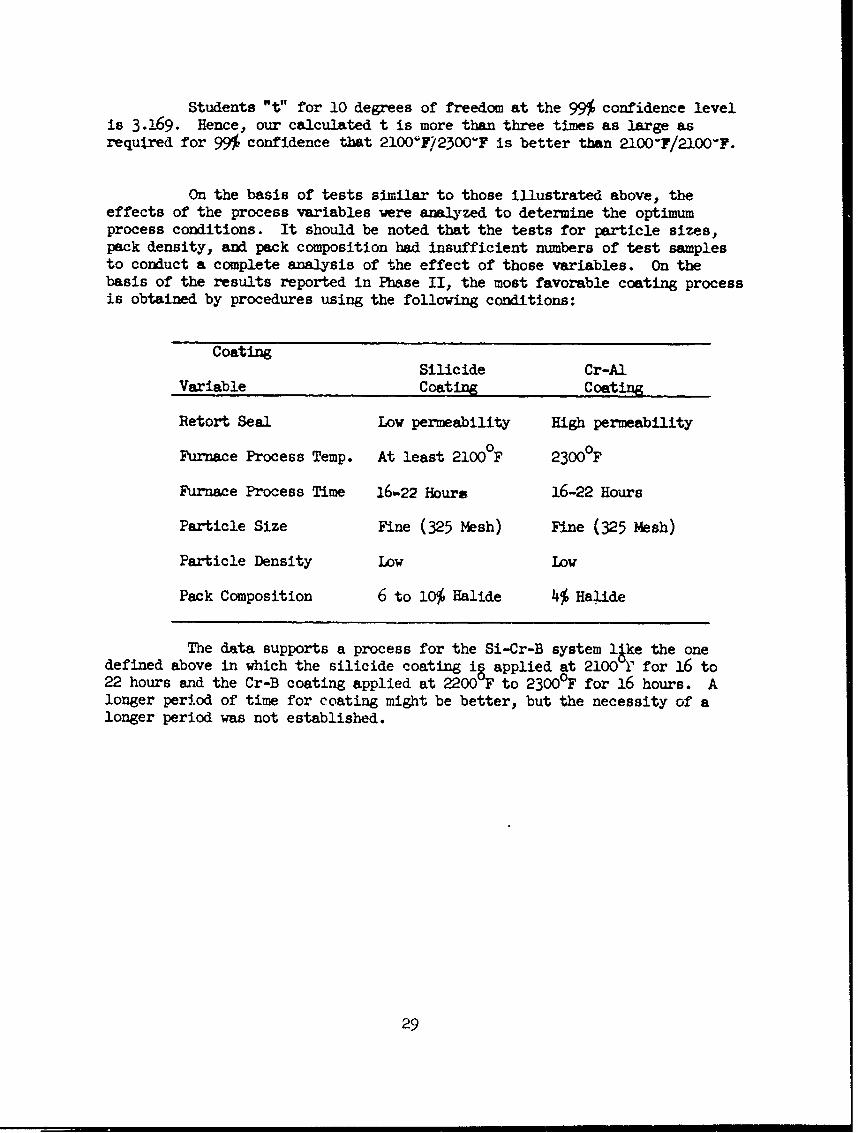
Students "t" for 10 degrees of freedom at the 99% confidence levelis 3.169. Hence, our calculated t is more than three times as large asrequired for 99% confidence that 2100F/25OOY'F is better than 2100F/2100-F.
On the basis of tests similar to those illustrated above, theeffects of the process variables were analyzed to determine the optimumprocess conditions. It should be noted that the tests for particle sizes,pack density, and pack composition had insufficient numbers of test samplesto conduct a complete analysis of the effect of those variables. On thebasis of the results reported in Phase II, the most favorable coating processis obtained by procedures using the following conditions:
CoatingSilicide Cr-Al
Variable Coating Coating
Retort Seal Low permeability High permeability
Furnace Process Temp. At least 21000F 2300°F
Furnace Process Time 16,-22 Hours 16-22 Hours
Particle Size Fine (325 Mesh) Fine (325 Mesh)
Particle Density Low Low
Pack Composition 6 to 10% Halide 4% Halide
The data supports a process for the Si-Cr-B system lke the onedefined above in which the silicide coating ig applied at 2100 r for 16 to22 hours and the Cr-B coating applied at 2200 F to 23000 F for 16 hours. Alonger period of time for coating might be better, but the necessity of alonger period was not established.
29

D. ANALYTICAL EVALUATION
Near the end of the Phase II process evaluation, an analyticalstudy was initiated by use of x-ray emission and diffraction techniquesand metallographic examination. This study was made on specimens coatedwith silicide only, the Si-Cr-Al system, and the Si-Cr-B system.
It should be mentioned that the coating components containingcolumbium are reported by the chemically synonymous name of niobium (Nb).This is necessary since the ASTM x-ray Power Data File lists the metal andits compounds by this nomenclature.
1. Silicide Coating. - Five Cb-lZr specimens coated with silicidewere examined by x-ray diffraction. These specimens were prepared as follows:(a) 1900 for four hours; (b) 1900OF for eight hours; (c) 1900°F for 16hours; (d) 19000 for 24 hours; and (e) 2100°F for 16 hours.
The specimen prepared at 1900OF for four hours was found to beincompletely coated, as shown by the presence of the characteristic niobiumdiffractions peaks in the diffraction pattern. Diffraction peaks were alsoobserved for Nb5Si 3 (tetragonal) and NbSi 2 .
A representation of the coating prepared at 2100OF for 16 hoursis shown in Figure 26. Diffraction patterns of the coating were obtainedon sections taken parallel to the specimen surface at 1/2 mil increments.A representative cross section of the coating at approximately 15OX is shownat the top of Figure 26. Photomicrographs of the surfaces were taken at eachincrement of thickness through the coating. Portions of these photomicrographsare shown in the figure at their approximate location in relation to the crosssection.
The chemical identifichtion directly below the cross section denotesthe composition found at that coating depth. Th- only component found in thisspecimen was NbSi 2 , oriented with the 110 crystal plane parallel to the metalsurface. An orientation of this nature would require that crystal growth beparallel to the 001 axis direction or perpendicular to the metal surface.The assumption of orientation in the 110 plane is based on the very strongreflections from the 110 and 220 planes and the reduced intensity of reflectionsfrom the 111 plane. A normal intensity distribution, corresponding to the ASTMdata, had been observed on earlier specimens.
2. Si-Cr-Al System. -- A Cr-I Zr soecimen was coated with silicideat 2100°F for 16 hours and Cr-Al at 2200 F for 16 hours and prepared for x-rayemission and diffraction studies as described in the Test Procedure. Thesex-ray determinations were made at approximately 0.0005 increments of coatingdepth. A representation of coating cross section at 150OX, qualitative coatingcomposition at various depths, and photomicrographs of the polished surface atvarious depths is shown in Figure 27.
30

Further emission analysis with miniature probes showed that thechromium content decreased rapidly as shown in Figure 27, and at a depthbelow about one-third of the thickness of the coating it constituted onlya small portion of the coating components. The niobium was found to bepresent throughout the coating, but at a low concentration where the chromiumwas high. The concentrations of the elements varied as would be expected for adiffusion process of this nature. The figure thus gives a good indicationof the extent of chromium diffusion during the 16-hour Cr-Al coating process.
Attempts to use a helium tunnel for determination of the lighterelements silicon and aluminum, with the 1 m miniature probe were unsuccess-ful because of the long range of the weak X-rays produced.
X-ray diffraction studies tended to support the findings in theemission studies. The coating compounds found in this study are shown inFigure 27 at th. -Approximate depths where each determination was made. Nearthe outer surface, NbAl,, A1Cr, and Alpha A120o were found to be present.At slightly greater dephs, the Nb Si 2 increased and Cr3Si and NbCr2 wereindicated. Gradually, all chromium and aluminum compounds disappeared andonly the oriented NbSi 2 was present. Nb5Si was observed in the Si-Cr-Alcoating only near the base metal coating inerface.
A group of curves showing the approximate change in coating composi-tion with thickness are shown in Figure 27. These curves are based on resultsof information obtained from X-ray emission analysis and X-ray diffractionstudies in conjunction with the metallographic studies. The percentage ofni obium and chromium at various coating depths was determined by comparingthe specific emission count rate of these components in the coating withcount rates produced by metal specimens containing known percentages of eachcomponent. The percentage of silicon was detelmined by using the composi-tion of the portion of the coating, near the base metal, composed of pre-dominately NbSi2 as a reference percentage of approximately 36 per centsilicon by weight. The ccmposition of aluminum was determined by differenceusing chromium, niobium, and silicon as the only other components in thecoating. It is realized that the compositions shown are only approximations;however, they were helpful as guides in determining the effects of relativeamounts of the various components in the coating.
3. Si-Cr-B System.-- X-ray diffraction and emission studies weremade similar to those on the Si-Cr-Al system. Emission determinations forboron content are unobtainable due to the extremely soft nature of the X-rays produced by this element. Analytical studies were conducted on theSi-Cr-B system on Cb-l Zr, C-102 and D-31 alloys. The coating processvariables were those specified as optimum in the statist.cal evaluation.
A representation of coating cross section, and approximate coatingcomposition at various depths is shown in Figures 28 and 29 for the Si-Cr-Bcoating on Cb-l Zr and C-103. A similar representation for the coating onD-31 alloy is shown in Figure 30; however, no attempt was made to determinecoating composition because of the presence of Ti in the alloy. The per-centages of either titanium or boron in the coating could not be determinedby emission analysis, making the determination of approximate compositioncurves impossible.
31

E. PHASE III
Work in Phase III was divided into three parts as follows: (1)determination of process reliability and reproductibility using infor-maticm and data from Phase I; (2) selection of techniques for coatingccmplex multi-ccoponent assemblies; and (3) delivery of coated testspecimens and a test assembly to ASD.
(1) Process Reliability and Reproducibility
In order to determine process reliability and reproducibility,three identical sets of test snecimens were coated and tested using thebest process techniques as determined in Phase II. These replicationspecimens were processed according to the optimum conditions determinedin Phase II. Me specimen were replicated and tested as indicated below:
Alloy Coating Retort Test Specimens in Each RunSystem 1st 2nd 3rd
Cb-I Zr Si-Cr-Al 1 1 1 3 oxidation - 2600"F2 bend elongation
Cb-i Zr Si-Cr-B 1 1 1 3 oxidation - 26o0F2 bend elongation
C-103 Si-Cr-A. 1 1 1 3 oxidation - 2600"F2 bend elongation
C-103 Si-Cr-B 1 1 1 3 oxidation - 2600"F2 bend elongation
D-31 Si-Cr-AI 1 1 1 3 oxidation - 2600"F2 bend elongation
D-31 Si-Cr-Al 1 1 1 3 oxidation - 2600"F2 bend elongation
The re sults of oxidation tests on the two optimized coatingsystems deposited on the three alloys are shown in Table 22. IximumtUie to failure and average life of each specimen group is shown in thetable. The average durability of the Si-Cr-Al coating for all replicatedruns tested at 2600"F was found to be 8,8 hours on Cb-1 Zr, 9 hours onC-103, and 10.9 hours on D-31. The average durability at 2600*F of theSi-Cr-B system was found to be 11.2 hours on Cb-1 Zr, 11.4 hours on C-103,and 11.5 hours on D-31.
Recent publications concerning coating for other refractorymetals, tungsten and molybdenu.n, indicated that difficulty has been ex-perienced -ith oxidation of silicide coatings at relatively low temp-eratures (l00o-1600OF). (References 32, 33.)
32

It was believed this difficulty might also be prevalent on silicidecoatings for tantalum and coiuabium. This phenomenon has been termed theIdi-silicide pest* and appears to be associated ith an intercrystalineoxidation of the di-silicide.
In order to determine the effects of such low temerature ox-idation a set of specimens were coated with both systems and tested inthis temperature range. The results of these tests are shown in Table23. As indicated on the Table, the test cycle consisted of successiveone hour exposures at 2000, 2400, 1000, 1200, 1400, 3600, 1800, 2000 and2400 0F. These results indicated a definite advantage of the Si-Cr-Bsysten over the Si-Cr-A1 system. All but two of the specimens coated withthe Si-Cr-B withstood the full low temperature cycle, while all thespecimens coated with Si-Cr-Al exhibited edge and face failures at temp-eratures between 14O0°F and 20000 F.
The Phase III replication tests also included bend specimenswhich were evaluated for resistance to oxidation after being elongatedvarious amunts on the transition temperature bend jig. (Figure 6)The procedure for conducting these tests are given in the section underTest Procedure. The results of these tests are shown in Table 214
These results showed that the optimised Si-Cr-Al system wascapable of being elongated to about 1% on Cb-lZr and C-103 without asignificant deocrease in oxidation resistance. Similar specimens ofCb-lZr and 0-103 coated with the Si-CrB system were capable of beingelongated about 2% before oxidation was noted in subsequent tests.
The specimens of D-31 coated with the Si-Cr-Al system broke intwo pieces in the bend fixture after elongations of .7% to 1.0%. Thesame alloy coated with the Si-Cr-p system also broke in two pieces afterelongation of about :L.4%.
It shouid be noted that all the coated specimens were elongatedwell past the normal 0.2% yield design value before there were any evidencesof oxidation noted in subsequent tests.
Evaluation of the reslts of these Phase III tests showed aslight advantage in oxidation resistance at 2600°F for the Si-Cr-B anda large advantage in low temperature characteristics. On the basis ofthese considerations it was decided that the remaining specimens andassemblies in Phase III could be coated with the Si-Cr-B system.
(2) Selection of Acceptable Coating Techniques for Fasteners
The selection of coating techniques for component parts andfasteners for complex assemblios was evaluated by preparation of repres-entative specimens fabricated with bolts, rivets, skin sections, weldsand structural stiffeners* Lmpqs of these specimens are shown inFigures 2 and 31 through 34.
33

Photographs showing the sequence of assembly ame shown in Figure 36.The assembly was coated in three steps in order to adhere to the rivetingand fastening sequence found to be best in earlier Phase III tests. Thecomponent parts were completely welded, formed and all holes drilled forriveting and fastening. The coating proced,'-ur cznsisted of depositing aninitial silicide coating on each of the component parts. The parts werethen riveted together into the complete assembly. A second silicide coatingwas then deposited on the assembly to cover areas which had been chipped inhandling and to cover the bare, upset portion of the rivets. The assemblywas then coated with the final Cr-B coating. A photograph showing thecompleted coated assembly is shown in Figure 37.
In order to better show the applicability of the structure, itwas decided to test it under glide re-entry conditions as simulated bypropane torch and ram-jet tests. These tests were performed by the VoughtAircraft and Missiles Division, Structures and Systems Laboratories.
The Propane Torch Facility consists of a variable number (1 to13) of 1" diameter propane torch heads mounted in a circular pattern.These torches are mounted on a movable dolly which may be brought toward astationary mounted specimen. Test temperatures up to 5000"F over a 10"diameter may be obtained, depending on gaseous mixtures and emissivityof test specimen materials.
The Ram-Jet Heater Facility consists of a 10-inch ram-jet burnerequipped with an 8-inch diameter Mach 1.5 exhaust no.z.e and a movablemodel support sting for test specimens. The ram-jet .-ner is capable ofproviding an 8-inch diameter exhaust gas stream at temperatures between1400" and 4000"F. The maximum exhaust gas pressure is approximately 55 psi,with an over-all sound pressure level near the nozzle of approximately 190decibels.
An idealized ccmbinatton of re-entry conditions for glide vehicleleading edge surfaces is shown in Figure 38. These conditions indicatethat during re-entry, such surfaces would encounter an approximate maximumtemperature of 2400'F and a maximum dynamic surface pressure of 800 psiwith an accompanying sound. level of 140 decibels.
These re-entry conditions in the combinations shown are unattain-able in one test facility. The ram-jet facility has sound and pressurelevels much too high if the specimens are brought to a temperature of 2400F.Conversely, if sound and pressure are adjusted to the proper levels, thetemperature is about 1600"F. Thus, a compromise was necessary to attainall of the re-entry conditions. For these reasons, it was necessary thatthe assembly be tested at .he proper sound and dynamic surface pressure

Examples of welded FS-82 alloy and riveted D-31 alloy test spec-imens coated with tie Si-Cr-B system are shown in Figure 31. This figureshows FS-82 alloy specimens prepared by lap weld and resistance spotweld methods. Weld specimens which were coated and tested for oxidationresistance at 2500°F included the following: three FS-82 lap weldspecimens, three FS-82 butt weld specimens, and three FS-82 resistancespot weld specimens. Oxidation tests at 2500OF on the butt weld specimensshowed no differenre in oxidation resistance between the welded and un-welded areas of the specimens. Similar oxidation tests on the lap weldand spot weld specimens indicated oxidation around the fayihg surfaceswhich indicited incomplete coatings in these areas. Examples of the lapveld and spot weld specimens exhibiting areas of oxidation around thefaying surfaces are shown in Figure 32. On the basis of these tests itwas decided that any later welds in components and assemblies shouldbe butt welds.
Typical examples of riveted lap shear specimens coated with theSi-Cr-B system are shown in Figure 33. A total of nine D-31 riveted spec-imens were prepared by three different coating procedures. The threedifferent procedures were as follows: (1) drill rivet holes, coat rivetsand specimen parts with silicide first coat, rivet, recoat with silicidecoating and coat with Cr-B final coat; (2) coat rivets and specimenparts with silicide first coat, drill rivet holes, rivet, recoat withsilicide coating and coat with Cr-B final coat; (3) drill rivet holes,rivet, coat with silicide first coat and coat with Cr-B final coat.These were tested for shear strength at 22000F. The results of the lapshear tensile strength tests are shown in Table 25.
On the basis of the preceding tests on riveted lap shear spec-imens, it was decided that the method to be used in the riveted portionof the later leading edge structure would be as follows: drill all rivetholes prior to coating; make all necessary welds, coat all componentparts with silicide first coat; make all rivet fastenings; coat withsecond silicide coat; coat with Cr-B second coat.
The work in the second portion of Phase III culminated in thefabrication and testing of a simulated leading edge assembly comprisedentirely of columbiun alloy components coated with the Si-Cr-B system.A drawing of the assembly is shown in Figure 34. All of the componentparts were fabricated by the Reearch uhnifact11 ing Group of the Astro..nautics Division of Chance Vought Corporation. Components were fabricatedfrom bare sheet, rod, and bar stock. The assebly was fabricated as partof the company sponsored research and development work on refractory alloys.After fabrication and coating the assembly was evaluated in typical re-entrycondi ions.
The purpose for fabricating, coating and testing the assemblywas to show the feasibility of employing different techniques of manufacturewhich had been shown to perform satisfactorily in earlier Phase III ox-idation tests. Examples of the butt welds used in the assembly are shown
35

levels in the Ram-Jet Facility. The assembly was tested at the maximudesired temperature in the Propane Torch Facility.
The temperatures attained in the Propane Torch Test are shownin Figure 39. It may be observed that a maximum temperature of 2500"Fwas reached, which exceeded the maximu re-entry temperature of 2350"Fas shown in Figure 38. The temperature was measured with an optical pyrom-eter and corrected with an assumed emissivity of 0.85. The total test timeabove 2000"F was 30 minutes with an idealized re-entry time of 25 minutes.A photograph showing the top surface and bottom side of the assembly afterthe ram-jet test is shown in Figures 40 and 41. The top surface shown wasthe surface exposed to the maximum temperature during the test. Thcre wasno evidence of oxidation on the surface or around the rivets after completionof this test. The appearance of the surface indicated the assembly would beable to withstand the re-entry temperature conditions for many more cycles.
The conditions attained in the Ram-Jet Facility are shown in Figure42. It may be noted that the sound level exceeded the test requirement of140 decibels by a level of 30 decibels. This represents a sound energylevel of approximately 10 times the level necessary to withstand there-entry conditions. It may also be observed that a dynamic pressure of1200 psi was attained, which also exceeded the re-entry condition require-ments of 800 psi.
There was no evidence of detrimental effects on the assembly duringthis test under the conditions of maximum sound level and surface pressureshown for the t-ic. c...t cor-itions in Figure 38. Structural failuredue to the combined effects of sound and pressure on the 1" unsupported.020" thick trailing edge did occur at the maximum points shown in Figure42. At these points, well above the required conditions of sound andsurface pressure, portions of the trailing edge broke and separated frumthe assembly. Close inspection after the test revealed no evidence ofoxidation or other detrimental effects on the coating except along Thebroken edges of the specimen. There was no sign of erosion damage to thecoating even around rivets, welds, or sharp edges.
A photograph showing the assembly mounted for test in the Ram-JetFacility is shown in Figure 43. A photograph showing the broken rear edgeof the assembly after the test was stopped is sho-in L" Figurc 44.
The results of the tests on the leading edge assembly in the pro-pane torch and ram-jet facilities indicates the coating is capable of with-standing oxidation and protecting the base metal along a leading edge underthe severe conditions of re-entry for a glide re-entry vehicle.

wOwUION
l. Bend tests indicate the three alloys (Cb-i Zr, C-103, and D-'31)coated with either the Si-Cr-Al or the Si-Cr-B coatings system my be bentat room temperature to a radius of 0.8' over a 1-1/20 length without visiblefailure. This minimum radius is believed to be adequate for flexing opera-tions required in handling and fabricating assemblies of the coated sheetmaterials.
2. Load cycle tests indicate the ability of the coated thin sheet(0.020') coluiu alloys to withstand thermal cycling to 2WOF under sus-tained load is highly dependent upon the stress level. This is shown by acomparison of specimens tested at loads of approximately 10% and 20% of theultimate strength at 25000F. Specimis which were thermafy cycled at 10%of ultimate withstood almst twice as many cycles as specimens stressed at20% of ultimate. This effect appears to be related to the creep ciarac-teristics of the alloys. Hm veer, the Si-Cr-Al and Si-Cr-B coatings systemhad sufficient &ctility to protect the alloys well past the usual 0.2%elongation used in design of siructures.
3, Optimization tests on the effects of process variables on oxidationresistance of the Si-Cr-Al and Si-Cr-B system indicated the followingconditions as being optimm:
Process .... r-Al or r-Variable First Coat Second Coat
Temperature 2100°F 2200OFTime 16 hours 16 hoursPack Density Unvibrated UnvibratedPack Particle Size fine (325 mesh) fine (325 mesh)Retort Seal Permeability low highHalide Content 6 to 10% 4%
4. The most oxidation resistant coating for 2600°F was found to bethe Si-Cr-B system deposited under the conditions shown in Item 3. Threeidentical sets of specimens with the two coating systems were prepared andtest/d with the foiLila9 r~iilrs&
Si-Cr-Al system Si-Cr-B system
HDurs at 200OF without Hours at 260OFfailure without failure
Aloy Max. Average (9 specimens) Max. Average(jCb-l Zr 1288 .i.C-103 13 9.0 15 11.4D-31 12 10.9 15 11.4
37

5. Recent literature on silicide coating. for tungsten and molybdenumreported a destructive low temperature oxidation effect termed "the di-slicide pest." Low temperature effects between i000 and 2000F on thetwo coating systems were determined for the coatings systems. It was foundthat the Si-Cr-B system exhibited excellent resistance in this range, aswell as at the higher temperatures. The Si-Cr-AClo sy.t ... == I'f--n + U", "
relatively poor resistance at the lower temperatures, although the resist-ance at the higher temperatures was good.
6. Analytical evaluation, including X-ray diffraction and emissionstudies in conjunction with metallographic techniques, revealed the follow-ing information about the two coatings systems:
a. The formation of NbSi2 appears to be at least a two-stepprocess that is both time and temperature dependent, involving the forma-tion of Ii 5 Si 3 and subsequent recombinations to NbSi 2 .
b. Orientation of The fh-Si 2 results from a lung period of time atelevated temperature and permits crystal growth to proceed in the mostdesirable direction from the thermodynamic point of vicw; and this appearsto be the (ll0).
c. The depth of penetration appears to be both a diffusion con-trolled and a reaction controlled mechanism, which tends to restrict thedepth of penetration of the compounds formed in the Cr-Al and Cr-B coatings.
d. The compounds NbCr2 , Cr3 S i; Al2Cr3, AI3Nb, All3 Cr4Si4 , and,NbSi2 were tentatively identified at various depths in the Si-Cr-Al coat-ings. However, no observations were made as wbIch was the most activecompound or compounds in affording oxidation rtistance.
e. The compounds NbCr2 , Cr3Si, NbSi2 , NbB2, and Fe2B were tenta-tively identified. at various depths in the Si-Cr-B coatings.
7. Various methods of fabricating and coating of columbium componentparts were evaluated and the best oxidation resistance was obtained by usingthe following techniques:
a. Rivete% c-.onent.s prepared first forming anddrilling all rivet holes. The drilled parts and rivets should be coatedwith the silicide coating. The parts are then riveted together and asecond silicide coat should be deposited on the Joined components. TheCr-Al or Cr-B should be deposited as a final coating.
b. Welded specimens containing coated butt welds, lap weld, andresistance spot welds were evaluated. The best oxidation resistance wasobtained with the coated butt welds.
c. Bolt specimens with Wentworth threads were coated and a satis-factory fit of the nut on the bolt was obtained.
38

8. A simulated leading edge assembly (12" long) containing weldsand rivets on the hot surface side of the structure was fabricated andcoated with the Si-Cr-B system. This assembly was tested in the VoughtPropane Torch and Ram-Jet Facilities under idealized re-entry conditionsfor a glide re-entry vehicle. The maximum temperature required in there-entry cycle was 2350'F, with a maximum dynamic surface pressure of 800pounds per square foot and a maximum sound level of 140 decibels. Thesimulated leading edge assembly satisfactorily exceeded the requirementsof the idealized re-entry conditions. In these tests, a maximum tempera-ture of 2500'F was reached with thirty minutes above 2000-F. The maximumsound level reached was 170 decibels (10 times the sound energy levelrequired) and a maximum dynamic surface pressure of 1200 pounds per squarefoot. At this sound and surface pressure level, the assembly experienced astructural failure on a one-inch width unsupported edge. There was noevidence of coating damage except along the broken edge.
39

TABLE 1.
ANALYSIS OF ALLOYS RECEIVED FOR COATING*
ALLOY Cb-I Zr C103 D31SOURCE Wah Chang Wah Chang duPontHEAT 8-2033 82199 3.54.5 - 744 31-007
Ingot Analysis Ingot Analysij Ingot Analysis AnalysisComposition. Per Cent Composition, Per Cent Composition, Per Cent
T Bottom TO BottomCb 9.7% 98.9% Cb 99.0% 99.17. HF 10.2% Ti 9.4%Zr 1.20% 1.00% Zr 0,88% 0.86% Ti 0.93% MO 10.6%
Cb Balance Ch Balance0 157 pa
Impurity Content, PPM Impurity Content, PPM Impurity Content, PPM N 30 ppmBottom Top Bottom C 805 ppm
C 430 <30 Al (20 420 Al .420N 130 130 B 11 1 B <1 Mechanical Prop.0 280 280 C 51 4 30 C 180 Cold WorkedH 0.8 1.3 I Cd' <~ 45 Cd 4.5B 14 11 Ce 20 /20 Cr ( 20 UTS 156,000Cd 45 < 5 Cr 20 420 Cu -440 YS 132,000CO < 20 ( 20 Cu 14 <140 Fe 4/00 Elong. (2") 1.7%Hf < 80 4 80 Fe < 100 < 100 Mg 4.20Fe < 100 <100 H 2.0 2.80 Mn z 20Pb (20 <20 Hf /80 8o MO <20Mn 20 20 Mg. < 20 <'20 N 82MO 25 20 Mn <20 420 Ni Z 20Ni <20 (20 Mo <20 420 Po /20Si <100 < 100 N 105 80 Si 41ooTa 430 - 300 Ni <20 /420 Sn 4 20Ti <150 < 150 0 270 170 V 4 20W <300 4300 Pb <2 20 W 137V < 20 4 20 Si (100 ( 100 Zn 4 20R.E. -/100 4100 Sn 4 20 4 20 Zr (500
Ta 430 4300Ti 4150 4150V / 20 < 20W 4300 4:300Zn <20 < 20
CONTINUED

TABLE 1
ANALISIS OF ALLO!S RECEIVED FOR COATING*(Continued)
ALiDY Cb-.1 Zr C 103 D-31SOURCE Wah Chang Wah Chan duPontHEAT 8-2033 82199 -.15, * 31-W07
Hardness in BHN Hardness in BHN
Average 102.5 Average 105R&ge 96.3 - 109 Range 100 - 109
Product Analysis PPM
Cb 98.51Zr 1.0%
4:"C 30H 1.0N 1100 260
Hardness
Average % 82
*Certified analysis by source

TABLE 2.STRENGTH OF REPRESENTATIVE COLUMBIUM ALILOYS
Reference 4
Alloy Crystallization Room Temp. 1600OF 2000OF 2200°F 2400F 25000FTemp. (1 Hr.) UTS YS % El. UTS YS % El, UTS YS % El. UTS YS % El. IS YS % El, UTS YS % E,
G.E. Fh8 poO F 122 110 16 65 43 19 4O 37 41 31 29 27 47
G.E. F50 250COF 122 30 24 50 34 28 35 27 35 21 17 45
FansteelFS-80 2200°F 60 46 17 14 10
FansteelFS-82 2200'F 82 70 11 65 52 7 45 40 8 10 7 80 12 11 53
FansteelS-83 38 3h 16 26 23 28
duPontD-31 22000F 100 92 22 34 33 12 25 22 14 17 8
duPontD-41 125 10 50 25 h5 30
duPontD-42 85 55
WestinghouseNC-31 103 100 17 43 34 5
WestinghouseNC-32 77 54 26 49 46 25
Wab ChangC-103 Cold Rolled 105 97 11 43 24 39 13 11 87
Wah ChangC-103 Recrystallized 56 42 33 27 18 45 12 10 92
Wah ChangCb-i Zr 2200°F 47 20 13 10

TABLE 3
RO1 TEMPERATURE STRENGTH OF 0.020"COATED AND UNCOATED COLUMBIJM ALLOYS 1
-T 17--1. 1 Y4..1A-A I III 4..4,. I &
rt.LJL~p %0 'J.JL .L a 16 1 9.. t#JAJI AAA
Strength,_ ,i Strength, psi Over 2"
C,-I Zr None 28,200 h8 ,900 16Cb-I Zr None 28 200 2900 18
Avg. Avg. h7,900 Avg. 17
D-31 None 136,000 157,200 3.0D-31 None 131900 157,300
Avg. 133,950 Avg. 157,20 Avg.
C-103 None 107,400 116,000 4.O112 i00 1189700 3.0
Avg. 109,900 Avg. 1 Avg.
NOTES: 1 Specimens as shown in Figure 1
43
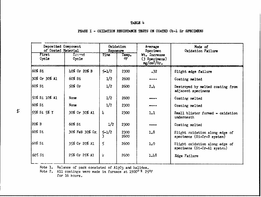
TABLE 4
PHASE I - OXDATION RESISTANCE TTS ON COATD Cb-i Zr SPECIMENS
Deposited Component Oxidation Average Mode ofof Coated terial E sure Specimen Oxidation Failure
First C,!nd Time Temp. Wt. IncreaseCycle Cycle OF (3 Specimens)
mg/cm2 /Hr.60% Si hO% Cr 20% B 5-1/2 2300 .32 Slight edge failure
30% Cr 30% Al 60% Si 1/2 2600 ... Coating melted
60% Si 50% Cr 1/2 2600 2.4 Destroyed by melted coating fromadjacent specimens
50% Si 10% Al None 1/2 2600 -- Coating melted
60% Si None 1/2 2300 ---- Coating melted
55% Si 5% Y 30% Cr 30% Al h 2300 1.1 Small blister formed - oxidationunderneath
20% B 60% Si 1/2 2300 ---- Coating melted
60% Si 30% FeB 30% Cr. 5-1/2 2300 1.8 Slight oxidation along edge of3 2600 specimens (Si-Cr-B system)
60% Si 35% Cr 20% Al 5 2600 1.0 Slight oxidation along edge ofspecinens (Si-Cr-Al system,)
601 Si 25% Cr 25% A] 2 2600 l.h8 Edge Failure
Note 1. Balance of pack consisted of A120 3 and halides.Note 2. All coatings were made in furnace at 19000 ± 250F
for 16 hours.

TA=l
PHASE I OXIDATION RESISTANCE I TS ONCOA~M SPECIMNS BEFCII OPTI11IZATION OF COATING SYSTEMS
Alloy Deposited Component Oxidation Exposure Average Specimenof Coated Material Weight IncreaseIst 2nd Average Temp. (Averag, of Three
Cycle Cycle Tie Hr "F Specirens ig/cW2/hr)
Cb-I Zr Si Cr-Al 5 2600 10
Cb-1 Zr Si Cr-B 5-1/2 2300 1.83 2600
C-103 Si Cr-Al 4-1/2 2600 3.3
%-103 Si Cr-B 4 2600 6.0
D-31 Si Cr-Ai 5 2600 3.1
D-31 Si, Cr-B 1 2600 2.3
Notis: 1. Balance of pack in each cycle consisted of AIg2O3 and halides.
2. All coatings were deposited at 1900w 125w' for 16 hours.
45

n
TABLE 6
TENSILE STRENGTH OF 0.0201; THICKCOATED COLUIBIUM ALLOYS 1 AT VARIOUS TEIPERAT RES
Alloy Test Coating2 Ult. TensileTemp. Strength, psi
OF
Cb-l Zr 75 Si-Cr-Al h9,200Gb-l Zr 75 Si-Cr-Al h9,400
Cb-l Zr 75 Si-Cr-B 49,800Cb-l Zr 75 Si-Cr-B 50,300
Cb-I Zr 2000 Si-Cr-Al 13,700Cb-l Zr 200 Si-Cr-Al 13,300
Cb-l Zr 2000 Si-Cr-B 13,200Cb-I Zr 2000 Si-Cr-B 13,4OO
D-31 2500 Si-Cr-Al 11,100D-31 2500 Si-Cr Al 10,700
D-31 2500 Si-Cr-B 11,000D-31 2500 Si-Cr-B 10,600
C-103 2500 Si-Cr-Al 11,700C-103 2500 Si-Cr-Al 10,900
C-103 2500 Si-Cr-B 11,200C-103 2500 Si-Cr-B 11,600
NOTES: iTransverse specimens, machined as shown inFigure 1
2 Coatings deposited on specimens in two cyclesSi first coat at 1900OF for 16 hoursCr-Al or Cr-B second coat at 1900OFfor 16 hours
46
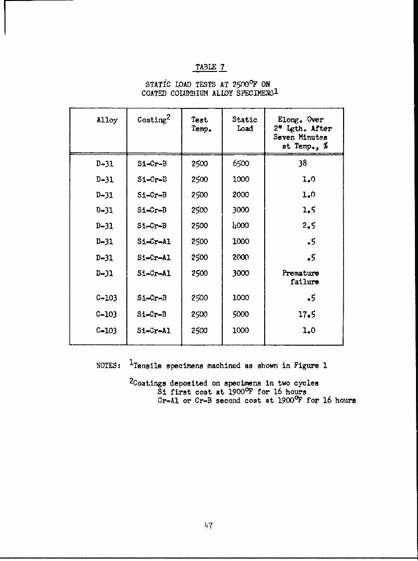
TABLE 7
STATIC LOAD TESTS AT 2500 0F ON
COATED COLUBIUM ALLOY SPECDhENS 1
Alloy Coating2 Test Static Elong. OverTemt,. load 2" Lgth. After
Seven Minutesat Temp., %
D-31 Si-Cr-B 2500 6500 38
D-31 Si-Cr-fl 2500 1000 1.0
D-31 Si-Cr-B 2500 2000 1.0
D-31 Si-Cr-B 2500 30001.
D-31 Si-Cr-B 2500 400Q2.
D-31 Si-Cr-Al 2500 1000 .
D-31 Si-Cr-Al 2500 2000.
D-31 Si-Cr-Al 2500 3000 Premature
failure
C-103 Si-Cr-B 2500 1000 .
C-103 Si-Cr-B 2500 5000 17*5
C-103 Si-Cr-Al 2500 1000 1.0
NOTES: 1Tensile specimens machined as shown in Figure 1
2Coatings deposited on specimens in two cyclesSi first coat at 1900OF for 16 hoursCr-Al or Cr-B second coat at 1900O'F for 16 hours
147
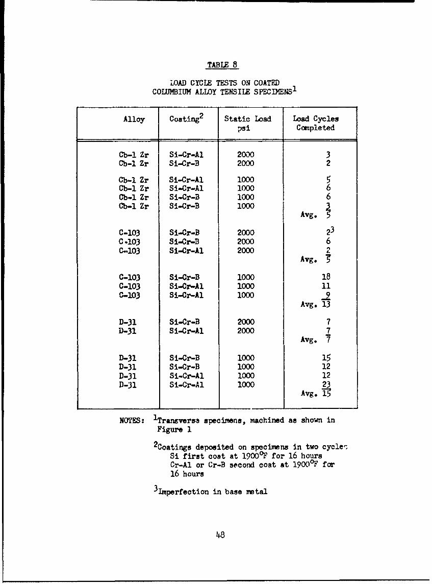
TABLE 8
LOAD CYCIE TESTS ON COATEDCOLUMBIUM ALLOY TENSILE SPECIMENS1
Alloy Coating2 Static Load Load Cyclespsi Completed
Cb-i Zr Si-Cr-AI 2000 3Cb-i Zr Si-Cr-B 2000 2
Cb-i Zr Si-Cr-Al 1000 5Cb-I Zr Si-Cr-Al 1000 6Cb-I Zr Si-Cr-B 1000 6Cb-I Zr Si-Cr-B 1000 Avg.
C-103 Si-Cr-B 2000 23C 103 Si-Cr-B 2000 6C-103 Si-Cr-Al 2000
Avg.
C-10.3 Si-Cr-B 1000 18C-103 Si-Cr-Al 1000 11C-103 Si-Cr-Al 1000 .2
Avg. 13
D-31 Si-Cr-B 2000 7D-31 Si-Cr-Al 2000 7
Avg. 7
D-31 Si-Cr-B 1000 15D-31 Si-Cr-B 1000 12D-31 Si-Cr-Al 1000 12D-31 Si-Cr-Al 1000 23
Avg. 1-
NOTES: ITransverse specimens, machined as shown inFigure 1
2 Coatings deposited on specimens in two cycle-Si first coat at 1900°F for 16 hoursCr-Al or Cr-B second coat at 1900°F for16 hours
31mperfection in base metal
48
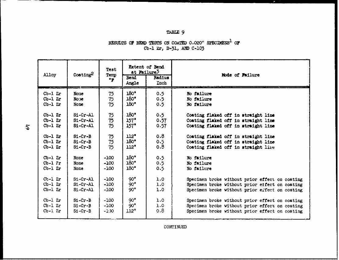
TABIE 9
RESUWS OF BEND TESTS ON COATD 0.020" SPECDSMS 1 OFCb-1 Zr, D-31, AMD C-103
Extent of BendTest at Failur3Alloy Coating2 Temp at-iue Mode of Failure
"F Bend RadiusAngle Inch
Cb-1 Zr Non 75 ]&0 0.5 No failureCb-l Zr NOtre 75 180" 0.5 No failureCb-i Zr None 75 180" 0.5 NO failure
Cb-l Zr Si-Cr-A 75 180" 0.5 Coatin flaked off in straight llne
Cb-1 Zr Si-Cr-Al 75 1(97 0.57 Coating flaked off in straight lineCb-i Zr Si-Cr-Al 75 157° 0.57 Coating flaked off in straight line
Cb-1 Zr Si-Cr-B 75 112 ° 0.8 Coating flaked off in straight lineCb-i Zr Si-Cr-B 75 12 0.5 Coating flaked off in straight lineCb-l Zr Si-Cr-B 75 112" 0.8 Coating flaked off in straight li:e
Cb-l Zr None -00 180 0.8 No failureCb-I Zr None -100 180 e 0.5 No failureCb-l Zr None -100 180* 0.5 No failure
Cb-i Zr Si-Cr-A -100 90" 1.0 Specimen broke without prior effect on coating
Cb-1 Zr Si-Cr-Al -100 900 1.0 Specimen broke without prior effect on coatingCb-l Zr Si-Cr-Al -100 900 1.0 Specimen broke without prior e-tect on coatingCb-l Zr Si-Cr-Al -100 90 1.0 Specimen broke without prior e .fect on coating
Cb-1 Zr Si-Cr-B -100 900 1.0 Specimen broke without prior effect on coatingCb-1 Zr Si-Cr-B -100 900 1. Specimen broke without prior effect on coatingCb-i Zr Si'Cr-B J -I,)O 1120 0.8 Specimen broke without prior effect on coating
COh'rINUED

TABIXE 9
(CONTINUED)
Extent of Bendcotn2 Test at Failure3
Alloy Coating2 Temp Bn j Radius Mode of FailureOF Bend IRadiusAngle Inch
D-31 None 75 1800 0.5 No failureD-31 None 75 180' 0.5 No failureD-31 None 75 1800 0.5 No failure
D-31 Si-Cr-Al 7 1350 0.V3 Coating flaked off in straight lineD-31 Si-Cr-Al 75 1120 0.8 Coating flaked off in straight lineD-31 Si-Cr-Al 75 900 1.0 Coating flaked off in straight line
D-31 Si-Cr-B 75 90" 1.0 Coeting flaked off in straight lineD-31 Si-Cr-B 75 01.0 Contivg flaked off in straight lineD-31 Si-Cr-B 75 112^ 0.8 Crating flaked off in straight line
D-31 None -100 180 0.5 io failureD-51 None -100 1350 0.66 Small crack along edge, metal defectD-)l None -100 1800 0.5 No failure
D-31 Si-Cr-Al -100 900 1.0 Specimen broke without prior effect on coatingD-31 Si-Cr-A-. -100 1120 0.8 Specimen broke without prior effect on coatingD-31 Si-Cr-Al -100 1120 0.8 Specimen brokee without prior effect on coating
D-31 Si-Cr-B -100 112" 0.8 Specimen broke without prior effect on coatingD-31 Si-Cr-B -10 ll2c 0.8 Specimen broke without prior effect on coatingD-.51 Si-Cr-B -100 1120 0.8 Specimen broke wiithout prior effect on coating
CONTINUED

TALZ 9(C-cn-inud)
Alloy Coating2 Test Extent of BendTerp. at Fail'lrp 3 Mode of FailureoF ,,Rnd Rad'*-L
Angle Trch
0-103 None 75 180 0.5 No fail'*i,C-103 None 75 180 O. 5.o failtreC-103 None 75 18) 0. fai',e
0-103 Si-Cr-Al 75 157 0.57 Coating flaked off in straight lineC-103 Si-Cr-Al 75 135 0.66 Coating fleaed off in straight lineC-103 Si-Cr-Al 75 110 0.5 No failure
C-103 Si-Cr-B 75 135 0.66 Coating flaked off in straight lineC-103 Si-Cr-B 75 157 0.57 Coating flaked off in straight line
%, C-103 Si-C,r-B 75 180 0.5 No failure
C-103 None -100 180 0.5 No failireC-!13 None -100 180 0.5 No failureC-103 None -100 180 o.5 No failure
C-103 Si ^r-Al -100 157 0.57 Coating flaked off in straight lineC-103 Si-Cr-Al -100 180 0.5 Slight flaking off of ooating along edgesC-103 Si-Cr-AI -100 180 0.5 Slight flaking off of coating along edges
0-103 Si-Cr-B -100 135 0.66 Coating flaked off in straight lineC-l')3 Si-Cr-B -100 180 0.5 Coating flaked off in straight lineC-133 Si-Cr-B -100 157 0.57 Coattng flaked off in straight line
NOTt.j: ISpecimens prepared as shown in Figure 12Coatings deposited on specimiens in two cycles - SI first coat at 1900°F for 16 hours
Cr-Al or Cr-B second coat at 19000F for 16 hours3 3end radius oIf 1-1/2" length of specien

TABLE 10
EFFECT OF VARTATIONS OF RETORT SEAT, PRMEABILITY AND COATING DEPOSITTON 7MRAT.E ONCOATtNG THICKMESSES AD OXDATION RESISTANCE FOR Cb-iZr SPiCTMES COATED IT.H TRE Si-Cr-Al SYSTEM
Retort -.Se. Process Coating Initial Specimns Replication Specimensermeabilit TOp. Thick.5121!ide Cr-At Ooth Inches. Avg.Exposure Mode of Oxidation Avg.EXposuje Mode of Oxidatior
lst 2nd Cycles) to Failurc2 Failure to Failure' FailureCycle Cycle OF j, y Hrs. OF
-75; TM TZ I W Coating malted ; : 24D CompleteLow High 1700 .0009 1 2400 Face & edges 1 2400 Along edgesHigh Low 1700 .001 1 21400 Face & edges 1 2400 Face & edgesHigh High 1700 .009 1 2400 Face 1 2400 Face & edges
Low Low 1900 ,016 1 250 Coating mlted 1 2500 Coating meltedLow High 1900 ,018 4 2600 Along edge 4 2600 Along edgesHigh Low 1900 -- . .... During processing 1 2400 Face P: edges
to
High High 190C --- 1 2OO Face &edges 1 2400 Face & edges
Low Low 2100 .003 1 2500 Coating melted I 2500 Coating meltedLow High 2100 .0039 8 2600 Along edges 6 2600 Along edgesHigh Low 2100 ,04 1 2400 Along edges 1 2100 Along edgesHigh High 2100 -- 1 2400 Face & edges 1 2400 Face & edges
Low Low 2300 ,005 1 2500 Coating melted 1 0500 Coating meltedLow High 2300 .0o6 1 2600 Along edges 1 2600 Along edgesHigh Low 2300 .. ---- During processing - -- Not rerun
High High 2300 -- . During processing . .... Not rerunTS. iRetort seal permeability denotes permeability nunber of approximately 0 for low and 400 for high.
2 Oxidation specimens as in Figure 1. Exposure consisted of one hour at 24000F, one hour at 2500 F;and 2600OF until failure.

TABLE n1
EFFCT OF VARIATIONS OF RETORT SEAL PERMABILITY AND COATIN DEPOSITION TEMMRATTRE ONCOATING THICKNESS ATTfl OXIDATION RESISTANCE FCR Cb-1 Zr SPECIMENS COATED 'VITH T E Si-Cr-B SYSTEM
Retort Seal Process Coating Initial cinens Replication SpecimensPerneabilityl Temp. Thick -v.xposur - Avg.EXposurMilcid Cr-B (Both Inches to Failure to Failurelt 2nd Cycles) Mode of Oxidation Mode of OxidationCycle Cycle OF Hrs. OF Failure Hrs. OF Failure
oW LOw 1700 .0010 1 2400 Gene'ral - - Not RerunLow High 1700 o0010 1 2600 Face & edges - - Not rerunHigh Low 1700 .0012 1 21400 General - - Not rerunHigh High 1700 .0013 1 2L00 General - - Not rerun
Low Low 1900 .G"18 1 2600 Coating Meclted 1 2600 Coating meltedLow High 1900 .0021 3 2600 Along edges 3 2600 Along edgesHigh Low 1900 .0023 1 25C0 Coating melted - Not rerunHigh High 1900 .0020 1 2400 General - - Not rerun
Low Low 2100 .0035 1 2600 Coating melted 1 2600 Uoating meltedLow High 2100 .0047 b 2600 General 5 2600 Along edgesHigh Low 2100 .005 1 2600 General - - N:ot rerunHigh High 2100 .0040 1 2,00 General - - "ot rerun
Lo0 LCw 2300 .0061 1 2600 CoeaLng melted 1 2600 Coating meltedLow High ?300 .c,69 1 2400 Along edges 1 2,00 Along edgesHigh Low 2300 .C-)65 - - During processtng - - Not rerunHigh High 23C .00614 - - During processing - - It rerI
N01 ': iRetort seal permeability denotes Perneability Number of approximately hO for low and 400 for high.2Oxidation specimens as in Figure 1. Fxposure consisted of one hour st 2VC07, one hour at 2500°F
and 2600F until failure.
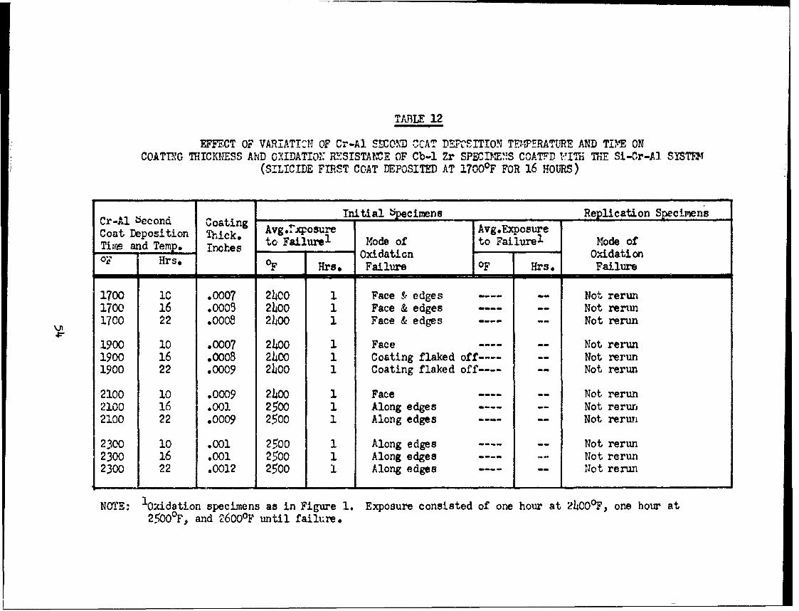
TABLE 12
EFECT OF VARIAT!I OF Cr-Al SMOND CCAT DE.,RcSITION TTERAT3E AND TiM ONCOATING THICKLESS AND OXIDATION I.SISTAME OF Cb-l Zr SP3IETN2S COATFD -IT E Si-Cr-A SYSTF
(SILICIDE FIRST COAT DEPOSITED AT 1700F FOR 16 i.ounS)
Initial !cimens Replication Specimens
Cr-A becond Coating Avg..iposure Avg.ExposureCoat Deposition Thick, to Failur 1 Mode of to Failure1 Mode ofTire and Temp. Inches Oxidation OxidationOF Hrse OF Hrs, Failure OF Hrs, Failure
1700 iC .0007 2400 1 Face & edges .. Not rerun1700 16 .000 2400 1 Face & edges .... .. Not renm1700 22 .0008 2100 1 Face & edges -- Not rerun
1900 10 .0007 2400 1 Face .-.. .. Not rerun1900 16 .0008 2400 1 Coating flaked off ---- Not rerun1900 22 .0009 2400 1 Coating flaked off ---- Not rerun
2100 10 .0009 2400 1 Face -- Not rerun2100 16 .001 2500 1 Along edges ------ Not rerun2100 22 .0009 2500 1 Along edges .... .. Not rerun
2300 10 .001 2500 1 Along edges ---- Not rerun2300 16 .001 2500 1 Along edges -- Not rerun2300 22 .0012 2500 i Along edges .... .. Not rerun
NOTE: 'Oxidation specimens as in Figure 1. Exposure consisted of one hour at 24000F, one hour at2,50 0°F, and 2600°F until failure.

TABI 1EFFECT OF VARIA ION OF Cr-Al S-rOND COAT DEPOSITION TEMPMATURE AM) TIME ON
COATING THICKNESS AND OXIDATION RESIS7A1UCE OF Cb-I Zr SFECMENS COATED WITh TIE Si-Cr-Al SYST(SILICIDE FIRST COAT DEPOSITED AT 19OO"F FOR 16 HOURS)
Cr-Al Second Coating Initial Specimens Replication SpecimensCoat Deposition Thick.Temp. and Time Inches Avg. Exposure Mode of Avg. Exoos Mode of
to Failure1 Oxidation Failure to Yailurel OxidationFailure
OF Hours Inches Hours OF Hrcurs OF
1700 10 .002 1 2500 Coating melted - --- Not rerun1700 16 .0019 2 2&0 Coating melted . ... Not rerun1700 22 .002 2 2630 Coating melted - Not rerun
1900 10 .0019 2 2&0 Along edge 3 2600 Along edge1900 16 .002 h 2600 Along edge 3 2600 Along edge1900 22 .002 h 2600 Along edge h 2600 Along edge
2100 10 0027 h 2600 Along edge h 2600 Along edge2100 16 .0028 4 2600 Along edge 5 2600 Along edge2100 22 .0031 5 2600 Along edge 3 2600 Along edge
2300 10 .003 5 2600 Along edge 5 2600 Along edge2300 16 .0035 7 2600 Along edge 6 2600 Along edge2300 22 .0035 7 2600 Along edge 6 2600 Along edge
NOTE: 1 Oxidation specimens as in Figure 1. Exposure consisted of one hour at 2400°F, one hour at 2500°F,and 2600°F until failure.

TABLE 14
EFFECT OF VARIATION OF Cr-Al SECOND COAT DEPOSITION TEMPERATURE AND TIME ONCOATING THICKNESS AND OXIDATION RESISTANCE OF Cb-l Zr SPECIMENS COATED WITH THE Si-Cr-Al SYSTEM
(SILICIDE FIRST COAT DEPOSITED AT 2100°F FOR 16 HOURS)
Cr-Al Second Coating Initial Specimens Replication SpecimensCoat Deposition Thick. Avg9. Exposure Mode of Avg. Exposure Mode ofTe , nd Time Oxidation Failure 0xidationOF Hours Inches Hours OF Hours OF Failure
1700 10 .0031 1 2500 Coating melted - -- Not rerun1700 16 .0031 1 2600 Coating melted .---- Not rerun1700 22 .0032 2 2600 Coating melted ---- Not rerun
1900 10 .0032 3 2600 Along edges 4 2600 Along edges1900 16 .0035 6 2600 Along edges 5 2600 Along edges1900 22 .0032 6 2600 Along edges 6 2600 Along edges
2100 10 .0038 6 2600 Along edges 5 2600 Along edges2100 16 .0039 8 2600 Along edges 6 2600 Along edges2100 22 .0043 7 2600 Along edges 7 2600 Along edges
2300 10 .0036 9 2600 Along edges 7 2600 Edges2300 16 0040 10 2600 Test stopped 9 2600 Along edge2300 22 .004h 10 2600 Test stopped 1 0 2600 Test stopped
NOTE: lOxilation specimens as in Figure 1. Exposure consisted of one hour at 24000F, one hour at 25000 Fand 2600OF until failure.

TABLE 15
EFFECT OF VARIATION OF Cr-Al SECOND COAT DEPOSITION TMPFRATT,1.F AND TIME ONCOATING THICKNESS AND OXIDATION RESISTANCE OF Cb-1 Zr SPECrWINS COATED V'ITHi THE Si-Cr-Al SYSTEM
(SILICIDE FIRST COAT DEPOSITED AT 2300°F FCR 16 Houms)
Cr-Al Second Inta Sec ns cation SpecimensCoat Deposition Coating Avg.Exposure " Avg.Exposel Mode of OxidatiorTermp. and Time Thick. Mode of Oxidation FailureOF Hrs. Inches OF Hrs. Failure OF Hrs.
1700 10 .005 2500 1 Coating melted ---- Not rerun1700 16 .005 2500 1 Coating melted ---- Not rerun1700 22 .006 2600 1 Coating melted ------ Not rerun
1900 10 .005 21400 1 Along edges ...... Not rerun1500 16 .005 2500 1 Along edges -- Not rerun1900 22 .c06 2600 2 Along edges ---- Not rerun
2100 10 .006 2500 1 Along edges -- Not rerun2100 16 .007 2500 1 Along edges ------ Not rerun21CO 22 .007 2600 1 Along edges ...... Not rerun
2300 10 .006 2500 1 Along edges ...... Not, rerun2300 16 .006 24OO 1 Along edges ---- Not rerun2300 22 .006 2500 1 Along edges -- Not rerun
NOTE: kxidation specimens as in Figure 1. Exposure consisted of one hour at 2400 0F, one hour at 2,O°F,and 2600°F until failure.

TABLE 16
EFFECT OF VARIATION OF Cr-B SECOiI) COAT DE-OSITIO:, TE1PCTURE A:D,) TIWE ONCOATING THICKNESS fND OXIDATION RESISTANCE OF Cb-1 Zr SECIME"S COATED 1ITH THE Si-Cr-B SYST-",M
(SILICIDE FIRST COAT DEPOSITED AT 19000F for 16 HOURS)
Cr-Al Second Coating Initial Specimens Replication snecimens
Coat Deposition Thick. ATemp. and Time Inches Avg. Exposyre Mode of Avg. Exnosure Mode of
to Failure Oxidation Failure to Failurel &Onidation
OF Hours Inches Hours OF Hours OF Failure
1700 10 .0019 1 2600 Coating Melted - - Not rerun
1700 16 .0020 1 2600 Coating Melted - - Not rerun1700 22 .0020 1 2600 Face - - Not rerun
1900 10 .0021 2 2600 Face and Edge 3 2600 edge1900 16 .0021 2 2600 Along Edge 2 2600 edge
1900 22 .0020 2600 Along Edge 3 2600 edgeC
2100 10 .0025 3 2600 Along Edge 3 2600 edge
2100 16 .0028 3 2600 Along Edge h 2600 edge2100 22 .0027 h 2600 Corner and Edge 4 2600 edge
2300 10 .0031 3 2600 Edge 3 2600 edge
2300 16 .0031 1 2600 Edge - - 'ot rerun
2300 22 .0030 1 2600 Edge - - Not rerun
Note: 'Oxidation specimens as in Figure 1. Exposure consisted of one hour at 24000F, One hour at 2500 0F,and 2600°F until failure. Specimens cooled and inspected after each exposure.

TABLE 17
EFFECT OF VARIATION OF Cr-B SECOND COAT DEPOSITION TEYPERATURE AND TIME ONCOATING THICKNESS AND OXIDATION RESISTANCE OF Cb-1 Zr SPECIYENS COATED WITH THE Si-Cr-D SYSTEM
(SILICIDE FIRST COAT DEPOSITED AT 2100°F FOR 16 HOURS)
Cr-B Second Coating Initial Specimens Rerlication SpecimensCoat Deposition Thick. Avg. Exposurel Mode of Avg. Exposure Mode ofTen pand Time Oxidation Failure Oxidation
oF Hours Inches Hours F Hours IF Failure
1700 10 .0040 1 2600 Coating melted ..---- Not rerun1700 16 .0042 2 2600 Face .. ... Not rerun1700 22 .0041 2 2600 Face ..---- Not rerun
11900 10 .00,b 3 2600 Along edge 4 2600 Edges1900 16 .0043 3 2600 Along edge 4 2600 Along edge1900 22 .O05 2 2600 Along edge 4 2600 Edges
J 2100 10 .0047 3 2600 Along edge 4 2600 Edges2100 16 .0047 4 2600 Along edge 5 2600 Edges2100 22 .0045 4 2600 Along edge 5 2600 Edges
2300 10 .0060 7 2600 Edge and Corners 7 2600 Edgea2300 16 .0062 8 2600 Face ani edges 7 2600 Edges2300 22 .0055 3 2600 Severe on face and edges 2 2600 General
*1I-
NOTE: "Oxidation specimens as in Figure 1. Exposure consisted of one hour at 2400F and 2600OF untilfailure. Specimens cooled and inspected after each hour exposure.

TABLE 18
EFFECT OF VARIATION OF SILICIDE FIRST COAT DEPOSITION TEMPERATURE AND TIME ONCOATING THICKNESS AND OXIDATION RESISTANCE OF Cb-1 Zr SPED.IMNS COATED V.ITH THE Si-Cr-Al SYSTEM
(Cr-Al SECOND COAT DEPOSITED AT 2200 F FOR 16 HOURS)
Si First Coat Finished Iitial Specimens Replication SpecimensDeposition Coating Avg. Exposure Mode of Avg. Exposure Mode ofep. and Time Thick. Oxidation Failure Oxidation Failure
Hours Inches Hours oF Hours O
1900 10 .0024 h 2600 Face and edges 4 2600 Edges1900 16 .0026 3 ---- Along edges 4 2600 Edges1900 22 .0027 6 2600 Along edges 7 2600 Edges
2100 10 .004 6 2600 Edges 5 2600 Edges2100 16 .ooh5 10 2600 No failure-test stopped 9 2600 Face2100 22 .0047 10 2600 No failure-test stopped 10 2600 No failure
o 2300 10 .0049 10 2600 No failure-test stopped 10 2600 Edge
NOTE: iOxidation specimens as in Figure 1, Test consisted of one hour exposure until failure. Aftereach hour specimens cooled to room temperature and examined.
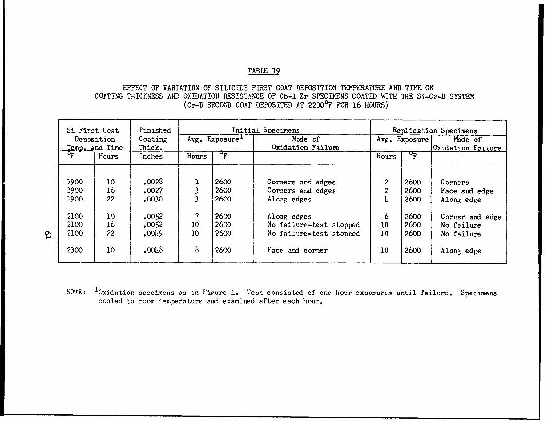
TABLE 19
EFFECT OF VARIATION OF SILICTE FIRST COAT DEPOSITION TEMP-RATURE AND Tfl{E ONCOATING THICKNESS AND OXIDATION RESISTANCE OF Cb-1 Zr SPECIMENS COATED WT THE Si-Cr-B SYSTEM
(Cr-B SECOND COAT DEPOSITED AT 22000 F FOR 16 HOURS)
Si First Coat Finished Initial Specimens Replication SpecimensDeposition Coating Avg. Exposure ! Mode of Avg. Exposure Mode of
Temp. and Time Thick. Oxidation Failure Oxidation FailureOF Hours Inches Hours F Hours OF
1900 10 .0028 1 2600 Corners and. edges 2 2600 Corners1900 16 .0027 3 2600 Corners aiad edges 2 2600 Face and edge1900 22 .0030 3 2600 Alo,-g edges h 2600 Along edge
2100 10 .0052 7 2600 Along edges 6 2600 Corner and edge2200 16 .0052 10 2600 No fsilure-test stopped 10 2600 No failure2100 22 .00h9 10 2600 Jo failure-test stoDDed 10 2600 No failure
2300 10 .008 8 2600 Face and corner 10 2600 Along edge
N3TE: 'Oxidation specimens as in Fipure 1. Test consisted of one hour exposures until failure. Specimenscooled to room 4imperature ar i examined after each hour.
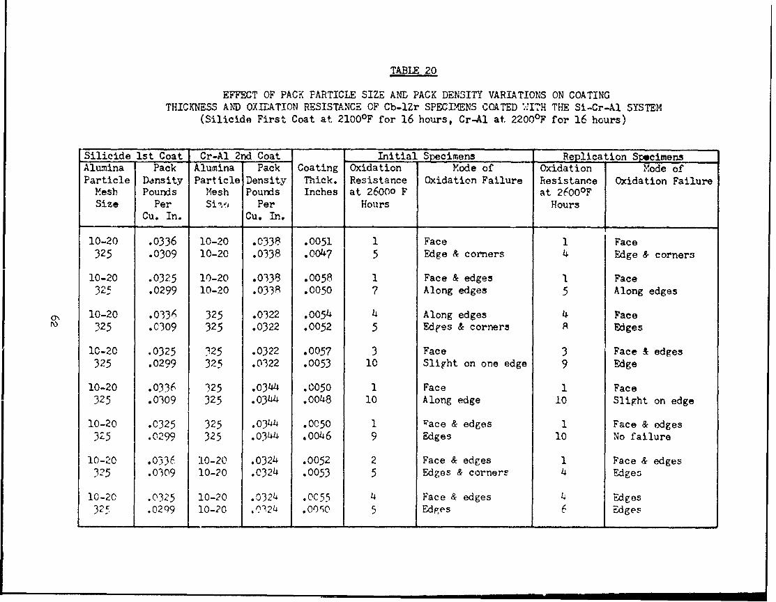
TABLE 20
EFFECT OF PACK PARTICLE SIZE ANL PACK DENSITY VARIATIONS ON COATINGTHICKNESS AND OXIDATION RESISTANCE OF Cb-lZr SPECImENS COATED ;-ITH THE Si-Cr-Al SYSTEM
(Silicide First Coat at 2100OF for 16 hours, Cr-Al at 2200°F for 16 hours)
Silicide 1st Coat Cr-Al 2nd Coat Initial Specimens Replication SpecimensAlumina Pack Alumina Pack Coating Oxidation Mode of Oxidation Mode ofParticle Density Particle Density Thick. Resistance Oxidation Failure Resistance Oxidation FailureMesh Pounds Mesh Pounds Inches at 26000 F at 2600°FSize Per Si-v, Per Hours Hours
Cu. In. Cu. In.
10-20 .0336 10-20 .0338 .0051 1 Face 1 Face325 .0309 10-20 .0338 .0047 5 Edge & corners 4 Edge & corners
10-20 .0325 10-20 .0338 .0058 1 Face & edges I Face325 .0299 10-20 .0338 .0050 7 Along edges 5 Along edges
oN 10-20 .0336 325 .0322 .0054 4 Along edges 4 Face325 .0309 325 .0322 .0052 5 Edges & corners A Edges
10-20 .0325 325 .0322 .0057 3 Face 3 Face & edges325 .0299 325 .0322 .0053 10 Slight on one edge 9 Edge
10-20 .0336 325 .0344 .C050 1 Face 1 Face325 .0309 325 .0344 .0048 10 Along edge 10 Slight on edge
10-20 .0325 325 .0344 .0050 1 Pace & edges 1 Face & edges325 .0299 325 .0344 .0046 9 Edges 10 No failure
10-20 .0336 10-20 .0324 .0052 2 Face & edges 1 Face & edges325 .0309 10-20 .0324 .0053 5 Edges & corners 4 Edges
10-20 .0325 10-20 .0324 .0C55 4 Face & edges 4 Edges32 .0299 10-20 .0324 .000 5 Edges 6 Edges

TABLE 21
EFFECT OF VARIATION OF HALIDE CONTENT IN RETORT PACK MLX. Oil COATIIGTHICIG ESS AND OXIDATION RESISTANCE OF Cb-i Zr SPECflDENS COATED WITH THE Si-Cr-Al SYSTEm4
(SILICIDE FIRST COAT DEPOSITEJ AT el0O°F FOR 16 HOURS Cr-Al SECOND COAT AT 2 .OO0F FOR 16 HOURS)
Halide Halide Coating Initial Specimens Replication SpecimensContent Content Thickness Avg. Excposure I .bde of Avg. Exposure Mbde of
in Si in Cr-A1 imils to Failure Oxidation Failure to Failure Oxidation FailureCoating Coating Hours Hours 'F.percent percent
6 4 5.4 7 2600 Edge 8 2600 Edge10 4 5.0 8 2600 Edge 8 e600 Edge14 4 4.7 6 2600 Edge 7 e60o Edge
6 7 5.5 5 2600 Edge 5 :o00 Edge10 7 5.] 6 2600 Edge 7 oOO Edge14 7 4.4 4 e6o0 Edge 4 2600 Edge
6 10 4.9 3 2600 Face and edge 3 2600 Face and edge10 1n 4.7 4 2600 Face and edge 4 2o00 Face and edge14 10 5.0 3 2600 Face and edge 4 2UO0 Face and edge
NOTE: Specimens cooled and inspected after each hour e::Posure.

RESULTS OF PHASE III OXIDATION TESTS AT 2600-F FOR DETERMINATIONOF RELIABILITY AND REPRODUCIBILITY OF THE
OPTIMIZED COATING SYSTEMS
REPLICATION RUN 1 REPLICATION RUN 2 REPLICATION RUN 3Exposure Mode of Exposure Mode of Exposure Mode of
Coating Specimen To Failure Oxidation To Failure Oxidation To Failure OxidationAlloy System Number (Hours) Failure (Hours) Failure (Hours) Failure
Cb-lZr Si-Cr-Al 1 12 Edge & Corner 10 Corner 11 Corner2 7 Edge 7 Edge 8 Edge3 9 Edge 8 Edge Edge
Average: 9.3 -T4Cb-lZr Si-Cr-B 1 10 Edge 12 Edge 9 Face
2 13 Corner 14 Face 10 Fact:3 11 Edge 11 Face 11 Face
Average: 11.3 12.3 10
01 C-103 Si-Cr-Al 1 8 Edge & Face 9 Edge 9 Edge2 13 Corner 7 Edge 9 Corner3 9 Edge Edge 8 Corner
Average: 10- -- 7U-103 Si-Cr-B 1 8 Edge 12 Edge & Corner 15 Edge
2 15 Corner 10 Edge & Corner 10 Face3 9 Corner 9 Edge & Corner 15 Edge
Average: 10.7 10.3 13.3
D-31 Si-Cr-Al 1 11 Edge 12 Corner 10 Edge2 8 Edge 11 Edge 12 Edge3 11 Edge 12 Edge 11 Corner
Average: 10 11.7 11
D-31 Si-Cr-B 1 8 Edge 13 Face 6 2.2 10 Face 9 Corner 15 Edge3 15 Edge 10 2. 1 j Corner
Average: 11 0.71
N(lE: 1. Specimens were cooled and inspected after each hour of exposure at 2b00F.
Coating affected by feilure of adjacent 3pecinen during test.

RESULTS OF LOW TMEATURE OXIDATION TESTSON OPTIMIZED COATINGS SYSTEMS 1
TtREPLICATION RUN I REPLICATION RUN 2 REPLICATION RUNTemperaturej Mode of Temperature Mode of Temperature Mode of
Coating Specimen At Failure Oxidation At Failure Oxidation At Failure OxidationAlloy System Number F Failure -F Failure .F Failure
Cb-lzr Si-Cr-Al 1 1400 Face 1400 Edge 1400 Edge & Face2 1400 Face 1400 Edge 1400 Edge & Face
Cb-lZr Si-Cr-B 1 1600 Edge Full Cycle - Full Cycle -
2 Full Cycle Full Cycle - Full Cycle -
C-105 Si-Cr-Al 1 1400 Face 2000 Face 1400 Edge & Corner
ON 2 1400 Face 1400 Edge & Face 1400 Edge
C-103 Si-Cr-B 1 Full Cycle - Full Cycle - 1800 Edge2 Full Cycle Full Cycle - Full Cycle -
D-31 Si-Cr-Al 1 1800 Edge 1800 Edge 2000 Edge2 1600 Edge 1800 Corner 1800 Corner
D-31 Si-ur-B 1 Full Cycle - Full Cycle - Full Cycle -
2 Full Cycle - Full Cycle - Full Cycle -
NOTE: 1. Test cycle consisted of successivre one-hour exposures at the following temperatures: 2400, 1000, 1200,1400, 1600, 1800, 2000 and 2400'F. bpecimens were coo±ed and inspected after each hour of exposure.

RESULTS OF OXL)ATION BEND TESTS ONOPTIMILED COATING SYSTEMS 1
REPLICATION RUN 1 REPLICATION RUN 2 REPLICATION RUN 3Elongation Mode Elongation Mode Elongation Mode
Coating Specimen At Failure of tit Failure of At Failure ofAlloy System .Number Percent Failure Percent Failure Percent Failure
Cb-lZr Si-Cr-Al 1 Damaged in 1.0 Oxidation on 1.0% Oxidation onhandling, tension side. edge.
2 Edge Oxidation at 2.0 Oxidation on
oxidation. edge. edge.Average: 1.5$ 75 1.A
Cb-lzr Si-Cr-B 1 2.5% Edge 2.,5 Oxidation at 2.0 Oxidation onoxidation. edge. edge.
2 2.5$ Edge 2 No failure. 2._4 No failure.Average: 2.5$ oxidation. 2.5J 2 .2
C-103 Si-Cr-Al 1 l.C O Oxidation on 1.0* Oxidation at 2.0* Oxidation on0 tension side. edge. edge.
2 1.0 Oxidation at 1. Oxidation at 2 Oxidation onAverage: 1.0* edge. .i edge. 2.0* edge.
C-103 Si-Cr-B 1 1.5 Oxidation at 1.5% Oxidation at 2.04 Oxidation onedge. edge. edge.
2 2 Oxidation at LOxidation at 2 OxidationAverage: 1. edge. edge. along edge.
D-3l Si-Cr-Al 1 .7% Broke in bend .9 Broke in bend 1.0 Oxidation onfixture. fixture. edge.
2 Broke in bend 1.4 Broke in bend . Broke in bendAverage: .7$ fixture. 1.0% fixture. .9 fixture.
D-31 Si-Cr-B 1 1.6% Broke in bend 1.5% Broke in bend 1.5 Broke in bendfixture. fixture. fixture.
2 Broke in bend l Broke in bend 1 Broke in bendAverage: l.i fixture. fixture. fixture.
NOTE: 1. See Test Procedure Section fur test method.2. Normal design requirements are based on 04 yield. All values shown above are well
pc.t poLit at which specriens took permanent set.
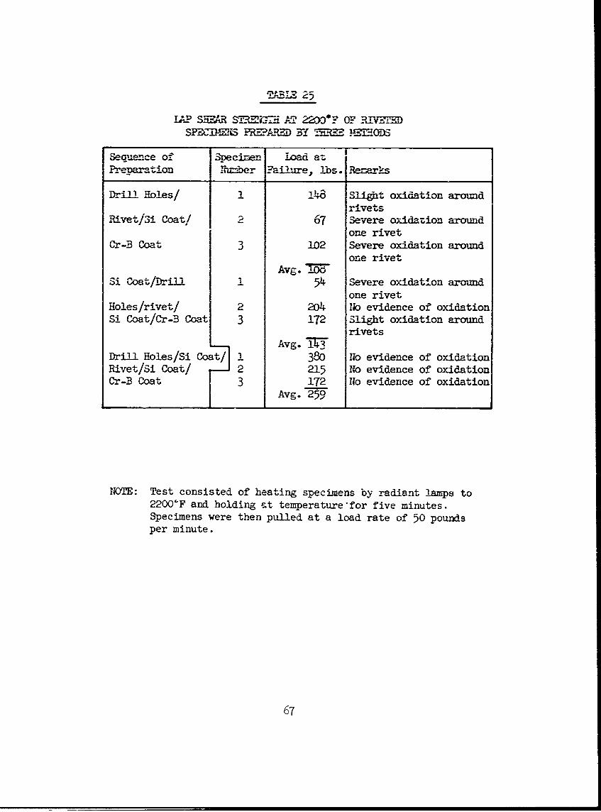
TABRIZ 2
TAP SM ', AT.W 22"OF T? IV =1SPDOMMES PIRDBY UZMD
Sequence of S-ecine- Load at I
Preara tion Nhnrber ?ai2ure, lbs. Rem arks
Drill Holes/ 1 148 Slight oxidation aroundrivets
Rivet/S! Coat! 2 67 Severe oxidazion aroundone rivet
Cr-B Coat 3 102 Severe oxidation aroundone rivet
Avg. =Si Coat/Drill 1 54 Severe oxidation around
one rivetHoles/rivet/ 2 204 No evidence of oxidationSi Coat/Cr-B Coat 3 172 Slight oxidation around
rivetsAvg. i7T
Drill Holes/Si Coat/ 1 380 No evidence of oxidationRivet/Si Coat/ 2 215 No evidence of oxidationCr-B Coat 3 172 No evidence of oxidation
Avg. 259
NOTE: Test consisted of heating specimens by radiant lamps to2200'F and holding st temperature for five minutes.Specimens were then pulled at a load rate of 50 poundsper minute.
67
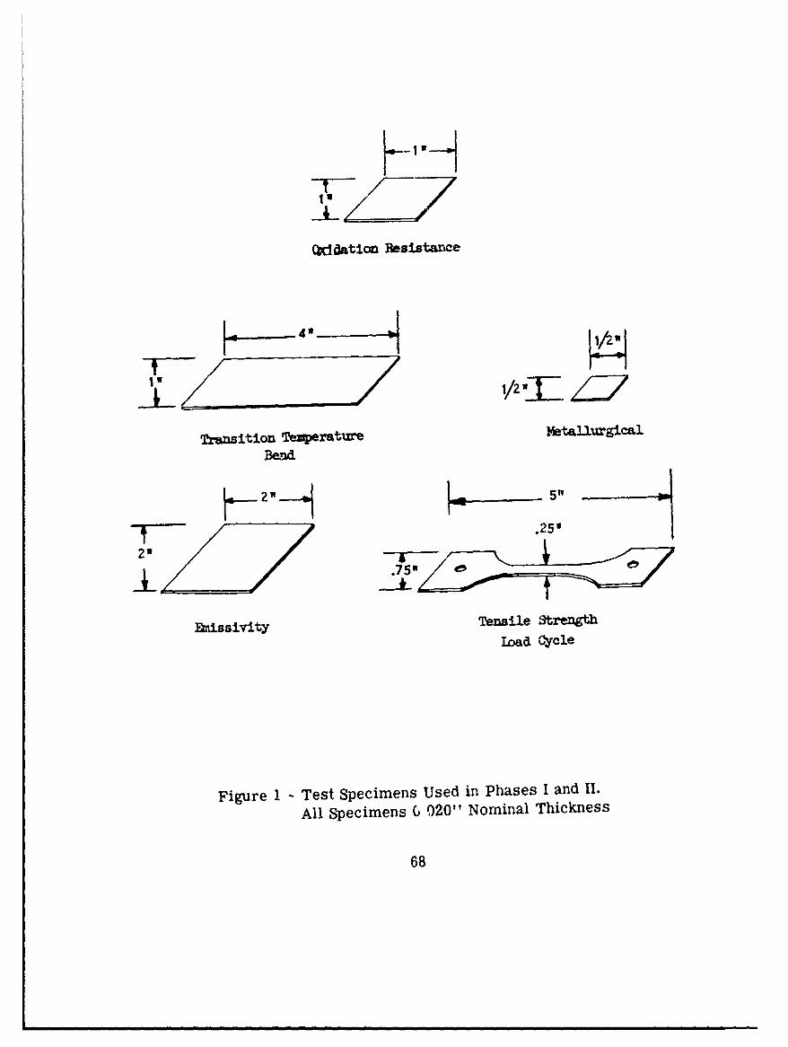
WdAatiofl Resistarice
Transition Temperature Mtallurgical
Bend
.25'
.75 4!5
&issivity Tensile Strength"ijd CYcle
Figure 1 - Test Specimens Used in Phases I and 11.
All Specimens G 020"1 Nominal Thickness
68

HOLE SIZE SPECIMEN
BUTT WELD SPECIMEN. OXIDATION RESISTANCE
21 / =/ EMISSIVITY METALLURGICAL
~4-42
TRANSITION TEMPERATURE BEND
Figure 2 - Test Specimens Used in Phase III
All Specimens 0.020" Nominal Thickness
69

i ~2/4 "-
PANEL SPECIMEN
L. 5w
5/4 R
__/,740
LAP-SHEAR SPECIMEN
5W1
1/4"
3/4W1
TENSILE STRENGTH LOAD CYCLE
ff 1/211
414
/ .94"12/2FATIGUE SPECIMEN
BOLT-WASHER-NUT SPECIMEN
Figure 2 - (Continued)
70

Shows tensile and o-cddation resistan1ce specimen placed oncoating rjack material
Figure 3 - Partially Loaded Retort
71
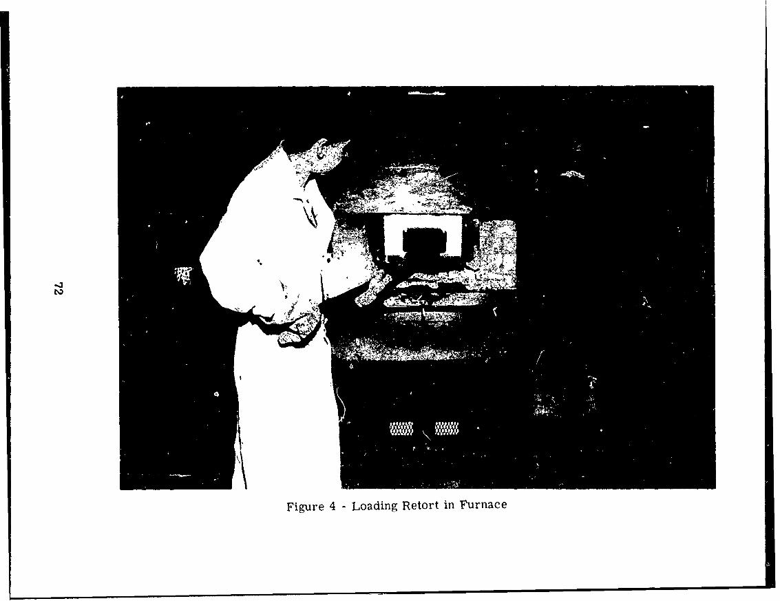
Figure 4 - Loading Retort in Furnace

Figure 5 -Con~trolled Air Flow Furnace

o -.-ab 1e CI a mD
BRend Test Snecinen U .loed 3end Aa-ve
Figure 6 T. Transition Temperature Bend Jio.
74

'9 - -0r -
4
Corner
Corner
Fgure 7 -Uncoated Cb-1 Zr (250X)
75

CM
Oenter
~nter Corner.
Figure 8 -Uncoated D -31 (250Y)~
76

corner
Ceter
Corner
Figure 9 -Uncoatedi C-103 (250X)
77

- ztZ
~- ~ i.,
- m~
Fiur 1 -UnoaedC-03Shwig n ncusoninth BseMeal(2rX
78~

- W11-
-,~. ~ ail
4v
Figure 11 - Gb-i Zr Coated with Si-Cr-Al Deposited in Two Cycles.1900'F for 16 Hours Each Cycle. (250X)
Figure 12 - Cb-1 Zr Coated with Si-Cr-B Deposited in Two Cycles.1900'F for- 16 Hours Each Cycle. (250X)
79

a ;~ -4;-. -~4-
Figure 13 - D-31 Coated with Si-Cr-AL Deposited in Two Cycles.1900OF for 16 Hours Each Cycle. (250X)
Figure 14 - C-103 Coated with Si-Cr-Al Deposited in Two Cycles.
1900'F for 16 Hours Each Cycle. (250X)
80

low ~ IP1001
;-...........
21000 P 23W* I
Figure 15 G b-i Zr Coated with Si Only, at Various Temperatures for 16 Hours
81

(a) I
Silicide Coating Onl.y Moving *Col-nnar Structure (25ox)
(b)Si-Cr-B Coating Depcusited with
Low Perrwability Retort -Sealfor the Cr-B Pack ;
S3i-Cr-B Coating Deposited withHigh Pernmability Retort Seal *.
for the Cr-B Pack
Figure 16 -Effect of Retort Seal Permeability on Deposition ofCr-B on the Silicide Coating
82
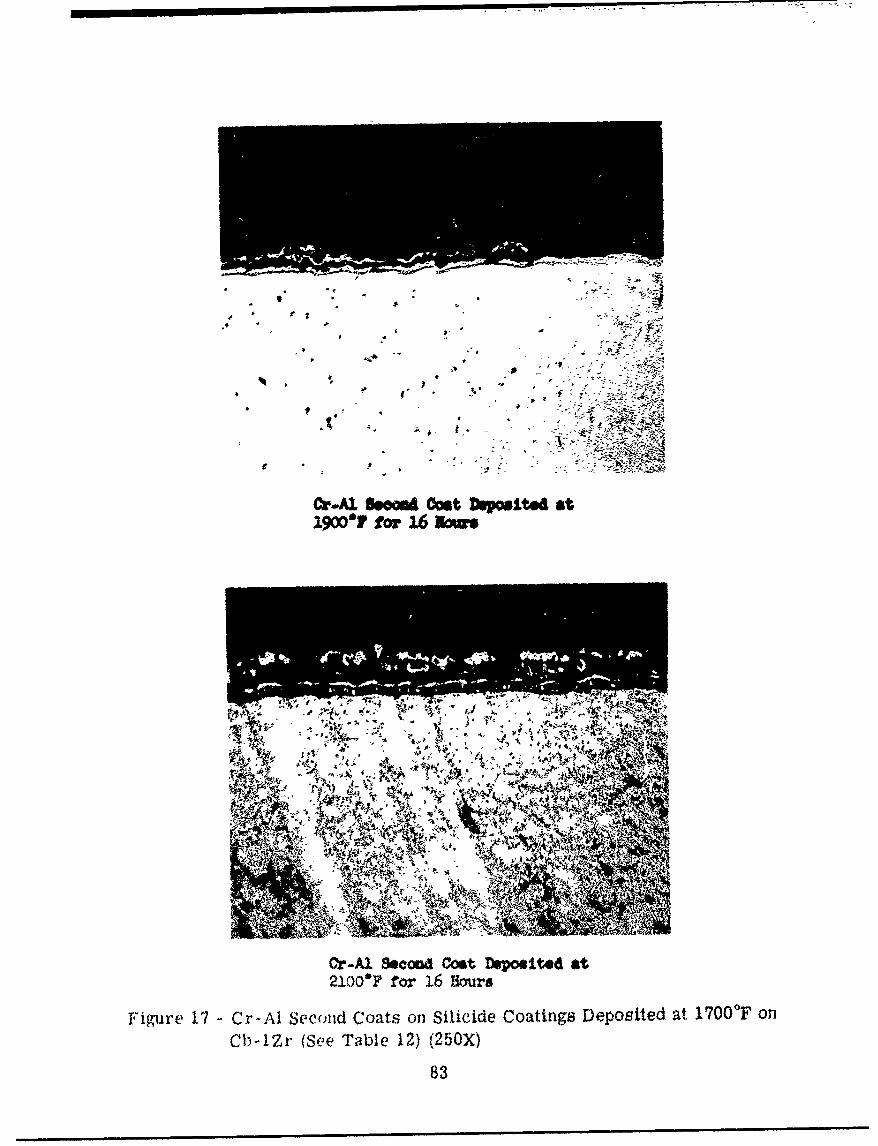
i- 7-- - M
4w A
A -R
C v
OrA) 6om Cst~Ail.~a1900?fo, 1 07,
Or-Al %cood Cost Depomited at21.0OF for 1L6 Hours
Figure 17 -Cr-Al Secoud Coats on Silicide Coatings Deposited at 1700'F on
Clb-lZr (See Table 12) (250X)
83

Cr~l sem& Mt Depoited st2300'? fo 2w16 Now&
Or-Al Scoa Oait 1wepod at,23X0*y for 16 Sours
Figure 18 - Cr-Al Second Coats on Silicide Coatings Deposited at1900'T on Cb-lZr (See Table 13) (250X)
84

Or-A1 Seond Ooat DeposIted at2300*F for 1.6 LNara
Figure19 - C -A3 econd Cost Siliid CatinsDpstda
2100"FF on Cb-IZr (See Table 14) (250X)
85

SUIcIft Coating DosiO±tda2100*F, Cr-Al Coating at 2300OFfor 16 Hours
Figure 20 - Oxidation Resistance Specimen Coated with the Si-Cr-Al Systemafter 10 Hours Exposure at 2600*F (See Table 14 and Figure 19)(250X)
86

W 3t
'its,
Ilk.~
O S-l 3000 Oast D~Ou1teu1 at2300'? for 16 Iowa
Figure 21 Photomicrographs of Cr-Al Second Coats on Silicide CoatingsDev' osited at 2300OF on Cb-lZr (See Table 15) (250X)
87
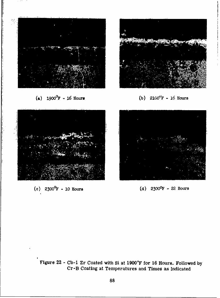
(a) 3.9W&F 16 Hours (b) 21CF -16 Hours
()23O0fDF -10 Hours (d) 2300OF -22 Hours
Figure 22 - Cb-l Zr Coated with Si at 19000*F for 16 Hours. Followed by
Cr-B Coating at Temperatu-res and Times as Indicated
88
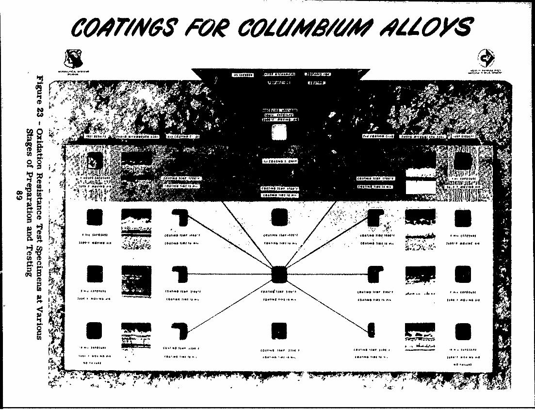
COATING!S F02 COI/MRe1d/ 4dLOK$-
Als-* A.. "
A, - Vr
at$ ff-. to-.c &,6C AH*141 o0.& VM ,
(4~~O a ,l W~
to& P~- m f96.9qa #11 . 66,6
A;4f
CD~ ~ ~ ~ ~ ~ ~~~ -8 89*8 0 *848P- - ,f * .P. . . ::
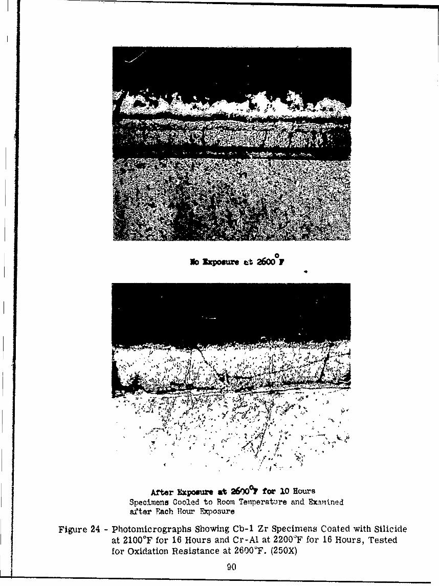
No0 Exposure t 260 F
456t
JA 7 ;
After Exposurt at 26%Ef7 for 1.0 HoursSpecimens Cooled to Room Terperat'ire anid Examitnedaf'ter Each Hour Expqosure
Figure 24 - Photomicrographs Showing Cb-1 Zr Specimens Coated with Silicideat 2100'F? for 16 Hours and Cr-Al at 220001F for 16 Hours, Testedfor Oxidation Resistance at 260O0F. (250X)
90

4j
At ~ efr ExpWur -t 26000? -v '~
I a 4* a.
A.2 WY f- v
-lllL ,.
After Exposure at 26000Y, for 10 Hours
Figure 25 - Photomicrographs Sniowing Gb-i-Zr Coated with Silicide at 21000Ffor 16 Hours and Cr-B at 220 for 16 Hours, Tested for OxidationResistance at 2600'F. (250X)
91

ri-------------
25 i_ - .
'e;
I~ ~ 7,-q A
50 X 0xx 50X Ox 50x 50X ,xFigure 26 - Representation of Results of Analytical Evaluation
of Cb-1 Zr Coated with Silicide First Coat Only

* 2:. *~jji.L±4 .......... '
11M~~~ -1!Mr 1
iM'
=90£ I
80
43 1 3a I::z bi 2 R8i
A1 5C KEA=i A1 rt1
7-1~ 53 .. !1 .. .-- Hex
10~1
Fiur 27 Rereenato of Anltclealuation of C-Ing
Allo Cote wit the Si-2AlCrA Syste
aA1 Al r Cr3 Si Al 5Cr 5Nb93

T 5-0 i
j. -t . 14- 'pCrangIT.- r l-L1 " * 1
IJ2T1 izutA Nb i M at:N s N I.Cr 3 ft Cr AjC~1C3 i~FeB Nb~r27P ; e. q
1:igre2 :!# Rers t tion nalytia Evlaio of. C-4. f+ M : 1 *l
50 , 0 0 0
Alloy Coate with the5S-rBSseV E H.- L 4

7=- = -::=----_ _ - . ;i
7 I~o~ ILI 8 entaio
CrS bi r3 iN2 2 ~ Nbi ~2 1
b~~ CrS CVUrS .r? br 2 b
:1 -7
C7-S
Figure 29%Rpeett o f Ant.aica vautino
b0 C4' 50Xi CrC iN0X2W b'2Ni bSITOC-103S Allo C oate wit the Si- StemB Nr
t C, t r N~r2r S 3 .? s.? r95-

k, 4t 4ag- .
4t -k. 1.2 mile~
®r, --Fe, j4 :4Y1. 1 .
J77 M ~jr
IT~ Cr Si ?NbSi2 NbSi 2 NbSi 2 Nb~i NbSi 2 '2 S 2 3 FeB NbCr 2 CrB t CrB W r2 Nb Si
Cr-.Si NbCr 2 ?NbCr 2 ? Cr Si. C 2 2rB 5 3~CBCr Si NbB? 3 r2S r2Nbr2 i
Fe2 B Bbr 3CI FeSi? 5 35 3 CCr B Nb 2 7 Fe 2B? 5 3
'3r -? FeB Nb Sit r bi2 Nb Si 5 3
1~~~~~' _______MOSi2
Fiue30-RprsnatoF -inltia vautoofD3 Cote with i--BSse
96
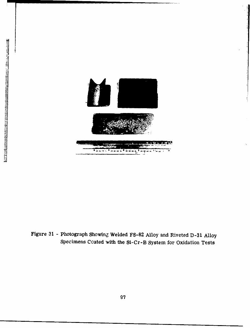
9' 1'
Figure 31 - Photograph Showing Welded FS-82 Alloy and Riveted D-31 AlloySpecimens Coated with the Si-Cr-B System for Oxidation Tests
97

Figure 32 - Photograph Showing Lap Weld and Resistance SpotWeld Specimens after Exposure for 1 Hour at 2500'F
98
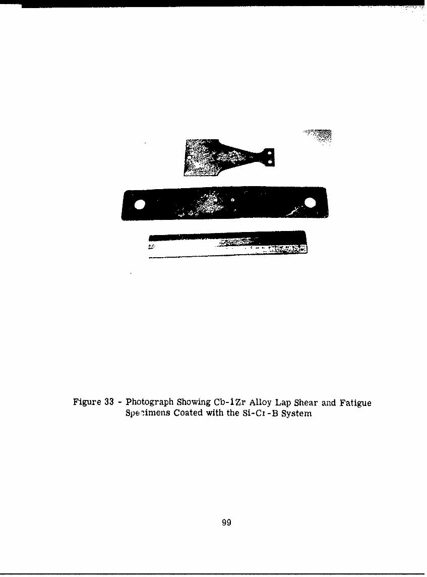
Figure 33 - Photograph Showing Cb-lZr Alloy Lap Shear and Fatigue
Spe.limens Coated with the Si-Cr -B System
99

BAR
+ +
+ ++Lr-
+ + + +
+ II+
+AR
ZZJ020 SKIN
040
,020 SKIN
,040
'064 *064
Figure 34 - Drawing of Simulated Leading Edge Assembly

Figure 35 - Welded Components of Simulated Leading Edge Assembly
101

5a
Underside of Outer Sk-in Surface Outer Skin With Skin Reinforcement
A II
Skin With Support Member for Eternal. oriplete Assembl:e Showing- AttachynentAttachment Ciip-*L~s Rivets and Bolts
Figure 36 - Photographs Showing Component Parts and Seoue.-cte ofBuildup of the Simulated Leading Edge Assembly
102

Aw03

1220.1
fir ri =111=V~t~- -
80 ~U) 40
wo
TIME MINUTE FRMSTR O E NTY
Fiue3 yia eetyCndtosfrLaigEg ufcof1 GldeVhil

IBi.
:--*
IL.
U).
00
TIME, MINUTES FROM START OF TEST
Figure 39 - Test Conditions for Simulated Leading Edge AssemblyDuridg Propane Torch Test

Figure 40 - Photograph Showing Top Surface of the Simulated LeadingEdge Assembly after the Propane Torch Test
106

Figure 41 - Photograph Showing the Bottom Side of the SimulatedLeading Edge Assembly after the Propane Torch Test
107

200Ir
200 1000 2500R
'4
w1% MAXIMUM DYNAMIC PRESS
160 Lj 80 2000 TIM
LEVEL AS SHOWN IN FIGURE 38 &E.+M
ww (L N
w IN FIGURE 38
w 1500-j 120
w 71 ... ....... tiz.f-T
0 Th.< I Nil
R ff 1;
(n 80 00, 1 00 1; 7t
+W4 4 It
+ CM
+&-14
40 200 avv t#14 1 ffliRi . .....
I U41111
END F TEST 14
0 qq n ut
0'0 10 20 30 40 so 60
TIME, MINUTES FROM START OF TEST
Figure 42 - Test Conditions for Simulated Leading Edge AssemblyDuring Ram Jet Test
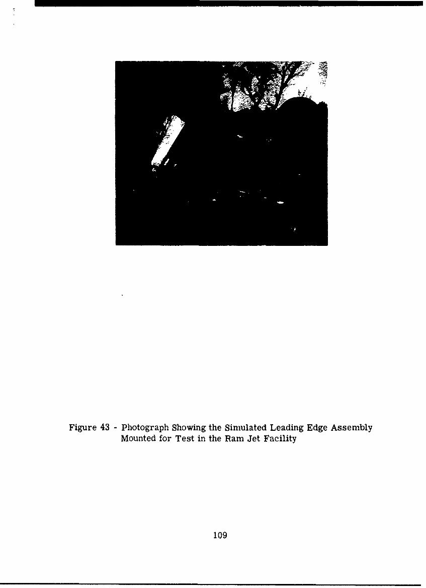
Figure 43 - Photograph Showing the Simulated Leading Edge Assembly
Mounted for Test in the Ram Jet Facility
109

Figure 44 - Photographs Showing the Broken Portion of the SimulatedLeading Edge Assembly
110

REFERENCES
1. Manufacltm Methods for Coluutbium Sheet, Crucible Steel Co. of America,lten Rport 1 to Mauacturing Nethods., I~qMM, AMC, Aeronautical Sys-
tems Center, Contract No, AF 33(6 00)-3991s2, 30 Noveber 1959.
2. Hansen., N,.Cositto of Binr Alloys, Second Edition, McGraw-HillBook Comnpany,,NwTr, 1956.
3. Sims, C. T., OXIation Behavior andl Protection of Refractory Metals,CORROSION, April 1960'.
I4. Snomim on Processing Materials for Rte-entry Structures, Society ofAicaft Materials and Process Engineers Symposium, WAflD Technical Re-port 60-.58, May 1960.
5. Klopp, W. D., Oxidation Behavior and Protective'Coatings for Coliumbiumand Columb*ium Base Alloys, DMIC Report 123, 15 January 1960.
6. Beach, J. G92 Faust, C. L., Electroplated Metals on Niobium, BMI-1004,May 24k, 1955.
7. Parr, E. D., Tulumello, Protective Coatings for Refractor Metals,,Suimiary of Second High Temperature Inorganic Refractory Coatings WorkingGroup Meeting, Discussion 31, WkADC Technical Report 59-I415, June 1959.
8. Ref ractor All= for Use as Structural Materials in Re-ent or BoostGlide Vehicles, General Electric Rport Ro. 6994, uarterly Rport No. 1to the McDonnell Aircraft Company, September 1, 1959.
9. Myers, J. R., High TeMperature Coatings for Aerospace Applications, Tech-nical Paper presented at the Aerospace FinishiJNg Symposium,. December 8-9,,1959, Fort Wrth, Texas
10. Gebler, K. A'., Report on Electrophoetic Techniques Emnployed at VitroCoaoration of America in 1WLT Technical Memorandum 58-139, 5 Deceumber1956, and Discussion 26, WAflC Technical Report 59-415, June 1959.
11. Deposition of Glaze Materials on Foam Ceramics by Electrophoresis, VitroLaboratories, Contract No. a(5)38-179.
12. Hirakis, E. C., Research for Coatings for Protection of Niobium AgainstOxidation at Elevated Temperatures, Horizons, Inc., Contract AF 33(616)-5356pFebruary 199.
13* New Products Data Sheet on Duplex Col mbumCoatE no arieMtlComipany, November 1, 1959.
III

3)4. Aves, W. L., nglilayr Metal-Cerac Coatings, submitted at Sunuary ofFirst High Temperature Inorganic Refractory Coatings Working Group Meet-ing, in Technical Memoradum VELT -TM 58-139, Dayton, Ohio, 5 Decerer 1958.
15. Ayes, W. L., Coating for Re-Entry. MAL PROGRESS, March 1959.
16. Ayes, W. L., Protective Coatings for Refractory Yetals, Sunnary of SecondHigh Temperature Inorganic Refractory Coatings Working Group Meeting,Discussion 30, WADC Technical Report 59-415, June 1959.
17. Ayes, W. L., Metal-Ceramic Coatings for the Protection of Graphite, paperpresented at the ational Symposium of the Ilectrochemical Society, Columbus,Ohio, October 1959.,
18. Ayes, W. L., Tailored Coatings, presented before the Third Meeting of theHigh Temperatu Inorganic Refractory Coatings Working Group, San Diego,January 27-29, 1960.
19. Sandoz, G., Coating Columbium for High Temperatures, JOURNAL OF METALS,April 1960, p. 340.
20. Developmnt and Evaluation of High Temperature Protective Coatirgs fori olmb llys Thompson-Ramo-Wooldridge, Inc. First Quarterly Pro.rssReport to rials Laboratory WWRCMP-3, WADD Contract No. AF 33(616)-7215,1 April 1960 to 30 June 1960.
21. Refractory Alloys for Use as Structural Materials in Re-entry or BoostGlide Vehicles, General Electrical Report No. 7148, Quarterly Report No.2 to the Monnell Aircraft Company, December 1, 1959.
22. Development and Evaluation of High Temperature Protective Coatings forClmium Alloys, First Quarterly Progress Report to aterial LaboratoryWMK-3, Wright Air Developrmnt Division, Air Research and DevelopmentCoemid, Contract No. AF 33(616)-7215, 15 July 1960.
23. Tripp, H. P., Quarterlj Report on the Develonment of Corrosion ResistantCoatings for Ise at High Temperatures, Gulton Industries, Inc., Report;n Contract No. AF 33(610-637M, Project No. 1 (1-308) ?or Lt. Lawrence N.Hjelm, WCLTEB, WADC, January 8, 1960.
24. Fugardi, J., Zambrow, J. L., Cladding and WeldiN of Stainless Steel toMolybdenum and Niobium, WADD, ontract AF 33(616)-3h92, October 199.
25. Fanateel Me tallugy, Fansteel Metallurgical Corp., July 1958.
26. Powell, C. F., Campbell, I. E., Gouser, B. W., Formation of RefractoryCoatings by Va r Deposition etods, Battelle Memorial institute,March 1949o
112
27. K1opp. W. D., Review of Recent Developmnts on Oxidation-Resistant Coatingsfor Refractory Metals, DIC Memorandu 102, 26 April 1961.
28. Jeffereys, R. A., Godd, J. D., Developent and Evaluation of High Temera-ture Protective Coat fr Coliim Alloys, Thompson-Rao-Wooldridge
Report T,-2771-67, 15 January 1961.
29. achteU, R. L., Protective Coatings for Refractory Metals, Sumiry ofSecond High Temperature Inorganic Refractory Coatings Workii GroupMeeting, Discussion 15, WACC Technical Report 59415, June 1959.
30. Priest, D. K., Chao, P. J., Develo t of a Cementation Coating Processfor High Te varature Protection of Molvbdenum, The Pfaudler Co. QuarterlyProgress Report No. I on Contract AF 33(616)-7192 prepared for WADD,15 July 1960.
31. Heine, R. W. and Rosenthan, P. C., "Principles of Metal Castings," McGraw-Hill Book Company, 1955.
32. Fitzer, E.; "Molybdenum Disilicide, A High Temperature Material,* ViennaInstitute of Technology, Plansee Proceedings of 195, Parogon Press Ltd.London, 1956.
33. Goetzel, C. G., lendler, P., Refractory Coatings for Tungsten, New YorkUniversity Research Division, Report on Contract AF 33(616)-6868, preparedfor WADD, October 1960, WADD MMHNICAL REPORT 60-825.
113