diffraction imaging in depth - z-terra.com...diffractions are the seismic response of small, but...
TRANSCRIPT

Geophysical Prospecting, 2008, 56, 627–641 doi:10.1111/j.1365-2478.2007.00718.x
Diffraction imaging in depth
T.J. Moser1∗ and C.B. Howard2†1Zeehelden Geoservices, van Alkemadelaan 550A, 2597 AV ‘s-Gravenhage, The Netherlands, and 2Zeehelden Geoservices, 2e de Riemerstraat184, 2513 CZ ‘s-Gravenhage, The Netherlands
Received October 2007, revision accepted February 2008
ABSTRACTHigh resolution imaging is of great value to an interpreter, for instance to enableidentification of small scale faults, and to locate formation pinch-out positions. Stan-dard approaches to obtain high-resolution information, such as coherency analysisand structure-oriented filters, derive attributes from stacked, migrated images. Sincethey are image-driven, these techniques are sensitive to artifacts due to an inade-quate migration velocity; in fact the attribute derivation is not based on the physicsof wave propagation. Diffracted waves on the other hand have been recognized asphysically reliable carriers of high- or even super-resolution structural information.However, high-resolution information, encoded in diffractions, is generally lost duringthe conventional processing sequence, indeed migration kernels in current migrationalgorithms are biased against diffractions. We propose here methods for a diffraction-based, data-oriented approach to image resolution. We also demonstrate the differentbehaviour of diffractions compared to specular reflections and how this can be lever-aged to assess characteristics of subsurface features. In this way a rough surface suchas a fault plane or unconformity may be distinguishable on a diffraction image andnot on a traditional reflection image.
We outline some characteristic properties of diffractions and diffraction imaging,and present two novel approaches to diffraction imaging in the depth domain. Thefirst technique is based on reflection focusing in the depth domain and subsequent fil-tering of reflections from prestack data. The second technique modifies the migrationkernel and consists of a reverse application of stationary-phase migration to suppresscontributions from specular reflections to the diffraction image. Both techniques areproposed as a complement to conventional full-wave pre-stack depth migration, andboth assume the existence of an accurate migration velocity.
I N T R O D U C T I O N
Diffractions are the seismic response of small, but structurallyrelevant, elements in the subsurface, like small near surfacescattering objects, or small scale faults, in general all objectswhich are small compared to the seismic wavelength. As such,they have a great potential for high-precision interpretation ofstructural details, and thereby to improve structural imagingand near-surface environmental studies. The high resolution
∗E-mail: [email protected], [email protected]†E-mail: [email protected]
of diffraction images may be, theoretically at least, related tosuper-resolution, which is the ability to image details beyondthe classical Rayleigh limit of half a seismic wavelength.
The importance of diffractions in high-resolution structuralimaging has been emphasized in several recent publications(Shtivelman and Keydar 2004; Bansal and Imhof 2005; Gras-mueck and Weger 2005; Taner, Fomel and Landa 2006; Fomel,Landa and Taner 2006). This paper may be considered in somerespects as a sequel to Khaidukov, Landa and Moser (2004),where many other references can be found. During the reviewprocess of Khaidukov et al. (2004), and subsequent discus-sion, it became clear that diffractions have still not made their
C© 2008 European Association of Geoscientists & Engineers 627

628 T. J. Moser and C.B. Howard
way into mainstream seismic processing and imaging, and thatthey are still cause for confusion. Therefore a motivation forthis paper is to further develop and elaborate on some ideaspresented in Khaidukov et al. (2004). First of all, we furthersubstantiate the claim that diffractions have been ignored inthe conventional processing sequence. We present some simpleand elementary examples to illustrate the fact that diffractionsare treated as noise in preprocessing, and, more importantly,are disregarded in seismic imaging. In fact, it may be arguedthat conventional reflection imaging does not even requirediffracted waves at all, to obtain coherent images of strongsubsurface reflectors. One of the proposals in Khaidukov et
al. (2004) is to provide the interpreter with two images: the re-flectivity image, for interpretation of the main reflectors, andthe diffraction image, to fill in the small, but potentially cru-cial, structural details. We further develop this theme showinghow the reflection and diffraction images can be used togetherfor high resolution interpretation.
A second motivation for this paper is to develop diffractionimaging in the depth domain and in the context of a conven-tional pre-stack depth imaging and migration velocity analysisworkflow. The success of imaging diffractions separately fromthe main wavefield depends on the quality of focusing, whichin turn implies an adequate migration velocity has been ob-tained. Several recent papers in fact use the focusing of diffrac-tions as a criterion for the quality of the migration velocity(Sava, Biondi and Etgen 2004; Fomel et al. 2006). Separationof diffractions from the main wavefield in the time domainhas the advantage that the focusing can be done ad hoc, thatis, for each trace and sample separately, and independentlyfrom the velocity model (Khaidukov et al. 2004; Taner et al.
2006). On the other hand, there are many situations wheretime imaging is insufficient to obtain an acceptable subsurfaceimage, due to lateral complexities and large velocity contrasts(Biondi 2006). In such situations, depth imaging and depth ve-locity analysis is warranted, even if the computational cost ishigher than for time imaging. In this paper we assume the po-sition that, after all the effort spent in obtaining a good depthimage and velocity, it is natural to take an additional step andperform diffraction imaging. This diffraction imaging is thenembedded in a pre-stack depth imaging context, and takes fullbenefit from the accurate velocity already constructed.
We define by ‘diffraction imaging’ any technique that imagesdiffractions separately, as opposed to the common ‘full-waveimaging’, which images the full recorded wavefield. We presentand further develop two new techniques for diffraction imag-ing in the depth domain, both of which form a diffractionimage by suppressing specular reflections. The first is based
on reflection focusing (Timoshin 1978) and justifies the claimmade in Khaidukov et al. (2004) that by stacking only over thereceiver leg of the classical diffraction stack, the stack effec-tively becomes a reflection stack. The reflection focus panelsare then an auxiliary domain, in which reflectivity is focusedto points which can be easily identified and used for designinga reflection attenuation filter in the data domain. Diffractionsare residuals of that filter and can subsequently be imaged sep-arately to obtain a diffraction image. The second techniqueapplies the fact that the classical migration loop can be sub-divided into a part that accounts for specular reflections anda part that does not. By designing an additional weightingfunction to the migration kernel, which consists in suppress-ing specular reflections, the migration results in a diffractionimage.
The paper is organized as follows. In the first section ‘Imageresolution and diffractions’, we present the relation betweendiffraction imaging and high- or superresolution. Here, we em-phasize the difference between data-driven and image-drivenresolution enhancement, and illustrate the inherent limitationsof the latter. The second section ‘Diffractions and conventionalprocessing’ makes the point that diffractions are ignored ortreated as noise, in conventional preprocessing as well as mi-gration. In the third section, ‘Diffraction imaging techniquesin depth’, we present the two techniques for diffraction imag-ing in the depth domain. A section on applications concludesthe paper.
I M A G E R E S O L U T I O N A N D D I F F R A C T I O N S
The primary goal of imaging, and diffraction imaging in par-ticular, is to obtain images of subsurface structural elementswith maximal sharpness, or resolution. A principal limit toresolution for images obtained from seismic data is posedby the Rayleigh criterion. This criterion gives a minimumto the size of resolvable detail, namely when the images ofthe details overlap within half a wavelength. It is argued inKhaidukov et al. (2004) that super-resolution, or imaging ofsub-wavelength size details, is possible under ideal circum-stances (and at least in theory), when diffractions are isolatedfrom the main wavefield and imaged separately. The argumentis that super-resolution amounts to an extrapolation of thesignal outside its frequency band, that this extrapolation ispossible when the signal is analytic, and that the signal is an-alytic when its source function support is limited. In practicalsituations there are many effects which challenge the possibil-ity of super-resolution, especially the presence of noise, but theargument shows that diffractions, which originate from small
C© 2008 European Association of Geoscientists & Engineers, Geophysical Prospecting, 56, 627–641

Diffraction imaging in depth 629
scale scatterers, qualify as the carriers of super-resolution in-formation. If one is interested in reliable high- or superresolu-tion of the image, based on the physics of wave propagation,then diffraction detection and imaging is the key technique.
Nowadays, many techniques exist that aim at enhanc-ing the image resolution and its interpretability. Many ofthese techniques operate on the image in the post-stack andpost-migrated domain, that is after the data gathers havebeen migrated and stacked (in whichever order). Examplesof such image-driven resolution enhancement techniques arecoherence analysis (Gersztenkorn and Marfurt 1999; Marfurtet al. 1998), instantaneous spectral attributes (Liu and Mar-furt 2007), and various structure-oriented filters (e.g., Fehmersand Hockers 2003). Since a seismic image may be thought ofas a convolution of a (multidimensional) band-limited waveletwith an infinitely sharp reflectivity distribution, there is somejustification for post-stack, post-migration image processing.However, it is important to realize that the scope of image-driven resolution enhancement is limited by the Rayleigh cri-terion. Moreover, incorrect migration velocities lead to appar-
Figure 1 Appearance of migration artifacts. a) model with syncline and simple graben, b) zero-offset section, c) migration using correct velocity,d) migration using a velocity which is too low. A false edge (migration artifact) is indicated by the arrow.
ent edges in the image, which will be detected as real edges,unless a pre-stack (diffraction) analysis is carried out.
We illustrate this in Fig. 1. Here a simple model consist-ing of a syncline and a narrow graben is constructed in aconstant-velocity background. Figure 1(b) shows a zero-offsetsection over this model, obtained by Kirchhoff (boundary-integral) modeling. Several phenomena can be distinguished.First, there is the main reflection from the plane interface.Then, there is the wavefront triplication and associated causticabove the syncline. Third, there are the edge diffractions orig-inating from the four edge points in the model. Fourth, thereare edge diffractions from the boundaries of the model, due toa finite aperture in the forward modeling. Several events areeasily identifiable and interpretable by means of zero-order raytheory: the main reflection and the triplicated branch. Otherphenomena are not predictable by standard ray theory: thecaustic diffraction at the wavefront triplication, and the edgewaves and their kinematic and dynamic behaviour. (It is infact very illustrative to follow these events also for non-zerooffsets but this is beyond the scope of this paper).
C© 2008 European Association of Geoscientists & Engineers, Geophysical Prospecting, 56, 627–641

630 T. J. Moser and C.B. Howard
Figure 2 Phase rotation of edge diffracted wave across its apex (indi-cated by the arrows).
Figure 1(c) shows the migration of the zero-offset sectionusing a correct velocity model, Figure 1d using a velocity thatis too low. The image for the correct velocity displays thesmooth syncline and has collapsed the edge waves to theircorresponding edges. For the image using the incorrect veloc-ity, the edge diffractions are unfocused but still recognizableas diffractions. However, the syncline has collapsed into a fo-cus point, which acts as a breakpoint in the reflector at thetrough of the syncline (indicated by the arrow). Any image-driven resolution enhancement algorithm will identify the ap-parent edge as a real edge and emphasize it (whichever waythe algorithm is organized). In summary, spurious edges willbe highlighted by post-stack attribute techniques with no realmeans of determining whether they are real or generated byusing an incorrect velocity model.
The main point of diffraction analysis and imaging here isthat a false edge can be unmasked as being false, by exam-ining its seismic response in the pre-stack data domain. Theseismic response from the syncline (caustic and triplication)is fundamentally different from the response from the edges(edge diffractions). This difference is most apparent in the mor-phology of the response and its kinematic characteristics. Asregards its dynamic characteristics, the amplitude at the fo-cal point or false edge is usually much higher than at the realedges (in fact making it even easier to incorrectly detect it asan edge). As a result, diffractions can be used to distinguishobjectively between real edges and migration artifacts.
The difference between diffractive and reflective responsegoes even beyond kinematics: the edge diffractions exhibit aphase shift of 180◦ across the diffraction apices (indicated byarrows in Fig. 2). See Klem-Musatov (1994) for details. Untilnow, the phase rotation of edge diffracted waves across their
Figure 3 Common data point gather at distance=3.5 km in the modelof Fig. 1, after NMO correction with constant velocity. Note that themain reflection has been flattened, but four diffractions, originatingfrom the four edges, are still curved, and hence will be suppressedafter stack.
apices has not been used as a criterion for their separationfrom the main wave field.
D I F F R A C T I O N S A N D C O N V E N T I O N A LP R O C E S S I N G
In this section, we outline the argument that high- or super-resolution information carried by diffractions has been deletedin the final stacked and migrated image - in other words, it isthen too late to extract it.
Preprocessing of seismic data, for structural imaging or(reservoir) property estimation, almost always includes astacking of pre-stack gathers, and hence a kinematical cor-rection of offset-dependent move-out (Normal Move-Out,NMO), with the aim of increasing the signal-to-noise ratio. El-ementary geometrical considerations, discussed in great detailin Khaidukov et al. (2004), show that the kinematic proper-ties of diffractions are different from those of reflections. Theimplication is that diffractions have different move-out prop-erties, and are therefore filtered out in the standard NMOand stack procedure, which is geared to stack data along re-flection curves. This is illustrated by Fig. 3, which displays acommon-midpoint gather in the model of Fig. 1, at the rightside of the double-edge system. The gather has been NMO-corrected with the correct constant velocity of the model, sothat the main reflection event (top event) is flattened. Despitethe use of a correct NMO velocity, however, the diffractionsfrom the four edge points appear as curved events, with a
C© 2008 European Association of Geoscientists & Engineers, Geophysical Prospecting, 56, 627–641

Diffraction imaging in depth 631
curvature which is increasing with the distance from the edgepoints. As a result they are suppressed, or filtered out, inthe stacking process. A different approach to preprocessingis therefore needed, if diffractions are to be preserved. Onechallenge is that they have weak amplitudes, compared to re-flections. Another challenge (for edge diffractions) is that theyare locally tangent to the reflections from smooth parts of thesame reflectors (Taner et al. 2006; Fomel et al. 2006).
On a more fundamental level, the classical (unweighted)diffraction stack for time or depth migration discriminatesagainst diffractions. This statement has been cause for contro-versy, because of the very terminology ‘diffraction stack’ it-self. For clarification we invoke Huygens’ principle. Huygens’principle for wave propagation defines a new wave front asthe envelope of waves emerging from virtual point sources ona previous wave front. The point source waves interfere con-structively along the new wave front, and destructively else-where. Huygens’ principle is equally valid for reflected waves(envelopes of elementary diffractions) and for edge diffrac-tions. However, this distinction between elementary and real
diffractions has long been overlooked in seismic imaging. Theelementary diffractions are mathematical idealizations that to-gether make up reflections from smooth reflectors, and are, assuch, not individually observable. Real diffractions originatefrom edges or small scattering objects, and are observable on aseismic section. The classical diffraction stack is based on thefact that, in the data domain, a reflection is the envelope of el-ementary diffractions, and in the image domain, a reflector iscomposed of elementary diffractors. The classical diffractionstack may take both elementary and real diffractions as input,but the envelope mechanism works only for the elementaryones. It is a correct statement, therefore, that reflector imag-ing does not need any real diffractions, as defined above in thissection. Another correct statement is that real diffractions arelost in the classical diffraction stack (again, despite its name),and that the latter is biased towards reflections. Of course, inspecial migration designs like the stationary-phase migration(Schleicher et al. 1997; Chen 2004), the bias against diffrac-tions is even more explicit.
Figure 4 offers an illustration. In Fig. 4(b) a reflector isdrawn, with two end points, and a very small fault in themiddle. Figure 4(a) is a zero-offset section over this model.The main reflection is clearly visible, as well as edge diffrac-tions from the two end points and from the central micro-fault. In fact, Figures 4(a) and 4(b) can be considered as mi-grated and demigrated versions of each other. If we reducethe number of scatter points along the reflector (Fig. 4d), thenfrom the associated zero-offset section (Fig. 4c) it becomes
clear, that the reflection is composed of elementary diffrac-tions. These elementary diffractions are indeed invisible in theoriginal reflection (Fig. 4a), which is their envelope. If we areable to extract the real diffractions from the full wavefield,and image them separately, we have diffraction imaging. Thisis illustrated by the bottom plots of Fig. 4: in Fig. 4(e) thereal edge diffractions, in Fig. 4(f) the image of the diffractingedges.
D I F F R A C T I O N I M A G I N G T E C H N I Q U E SI N D E P T H
There are several motivations to study diffractions in the depthdomain. The appearance of diffractions in the seismic data isusually evidence for strong complexities and a strongly inho-mogeneous trend model. Such complexities can invalidate theassumptions of time migration (local lateral homogeneity), sothat pre-stack depth imaging is then the method of choice.Pre-stack depth imaging is more labour and compute inten-sive than time imaging, due to the migration velocity analysisand the computation of travel time tables. On the other hand,the success of identifying and isolating diffractions depends onthe quality of focusing or the accuracy of the velocity model.It is therefore a natural step to complement the full-wave pre-stack depth imaging with a diffraction analysis and -imagingstep, where full benefit is taken from the already constructedvelocity model. If the velocity model is accurate and detailedenough for an optimally focused full-wave depth image, thenfor the diffraction image no additional focusing is needed.
In this section, we present two techniques for diffractionimaging in the depth domain: reflection focusing and the anti-stationary phase filter. Both approaches are tested and illus-trated on the Cassis data set (provided by Total/Opera, Pau).This is a Marmousi-like model with channel structures in thedeeper sections, embedded in a set of horizontal plane reflec-tors. For comparison, reference and the ease of exposition ofthe diffraction imaging techniques, we first present a full-wavepre-stack depth imaging (Figs 5 and 6). A conventional full-wave Kirchhoff migration (Hubral, Schleicher and Tygel 1996)applies the classical diffraction stack
V(x) =∫
dt ds dr w(s, x, r) U(t, s, r) δ(t − td(s, x, r)), (1)
and uses a stacking travel-time trajectory given by
td(s, x, r) = T(s, x) + T(x, r), (2)
where U(t, s, r) are the full-wave data, depending on time t andshot/receiver position s/r, and δ the Dirac delta function. The
C© 2008 European Association of Geoscientists & Engineers, Geophysical Prospecting, 56, 627–641

632 T. J. Moser and C.B. Howard
Figure 4 a) zero-offset section over a plane reflector segment with a small fault. Note diffractions from the fault and the edges of the reflector. c)decomposition of zero-offset into edge diffractions and a finite number of elementary diffractions. e) edge diffractions. b), d), f) migrated imageof the data in the left panels.
reflectivity image is given by V(x), depending on the subsur-face image point x. The weighting function w(s, x, r) is chosenequal to one here. The stacking travel-time trajectory td(s, x,r) represents the travel time of an elementary diffraction fromthe image point x, and plays a crucial role in the envelope
mechanism, described in the section ‘Diffractions and conven-tional processing’. T(s, x) is the travel time from s to x (andsimilarly for T(x, r)), which may be multivalued in case ofmultipathing. For a sufficiently dense grid covering the source-receiver acquisition, the travel times are pre-computed by ray
C© 2008 European Association of Geoscientists & Engineers, Geophysical Prospecting, 56, 627–641
Diffraction imaging in depth 633
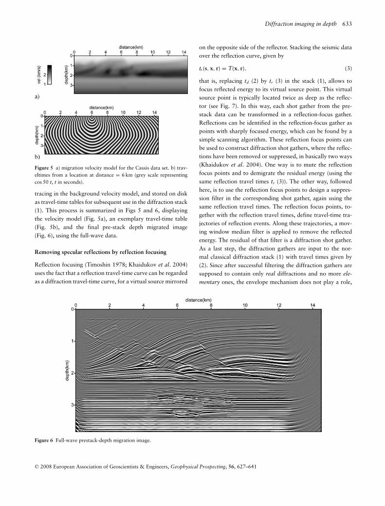
Figure 5 a) migration velocity model for the Cassis data set. b) trav-eltimes from a location at distance = 6 km (grey scale representingcos 50 t, t in seconds).
tracing in the background velocity model, and stored on diskas travel-time tables for subsequent use in the diffraction stack(1). This process is summarized in Figs 5 and 6, displayingthe velocity model (Fig. 5a), an exemplary travel-time table(Fig. 5b), and the final pre-stack depth migrated image(Fig. 6), using the full-wave data.
Removing specular reflections by reflection focusing
Reflection focusing (Timoshin 1978; Khaidukov et al. 2004)uses the fact that a reflection travel-time curve can be regardedas a diffraction travel-time curve, for a virtual source mirrored
Figure 6 Full-wave prestack-depth migration image.
on the opposite side of the reflector. Stacking the seismic dataover the reflection curve, given by
tr (s, x, r) = T(x, r), (3)
that is, replacing td (2) by tr (3) in the stack (1), allows tofocus reflected energy to its virtual source point. This virtualsource point is typically located twice as deep as the reflec-tor (see Fig. 7). In this way, each shot gather from the pre-stack data can be transformed in a reflection-focus gather.Reflections can be identified in the reflection-focus gather aspoints with sharply focused energy, which can be found by asimple scanning algorithm. These reflection focus points canbe used to construct diffraction shot gathers, where the reflec-tions have been removed or suppressed, in basically two ways(Khaidukov et al. 2004). One way is to mute the reflectionfocus points and to demigrate the residual energy (using thesame reflection travel times tr (3)). The other way, followedhere, is to use the reflection focus points to design a suppres-sion filter in the corresponding shot gather, again using thesame reflection travel times. The reflection focus points, to-gether with the reflection travel times, define travel-time tra-jectories of reflection events. Along these trajectories, a mov-ing window median filter is applied to remove the reflectedenergy. The residual of that filter is a diffraction shot gather.As a last step, the diffraction gathers are input to the nor-mal classical diffraction stack (1) with travel times given by(2). Since after successful filtering the diffraction gathers aresupposed to contain only real diffractions and no more ele-
mentary ones, the envelope mechanism does not play a role,
C© 2008 European Association of Geoscientists & Engineers, Geophysical Prospecting, 56, 627–641

634 T. J. Moser and C.B. Howard
Figure 7 Geometry of reflection focusing. The reflection on the dis-played reflector is focused to its own focus point, and is kinematicallyequivalent to a point diffraction from that point.
and each real diffraction is stacked and imaged to its owndiffractor.
We make several comments to this procedure. First, the re-flection focusing was proposed in Khaidukov et al. (2004)for application in a macro-model independent context. Herewe demonstrate that the procedure also works when usingan available depth velocity model and using the reflectioncurve (3). Second, it is an interesting question which velocity isneeded at the mirror side of the reflector, to make sure that thereflection is focused in one point. For shallow reflectors, wemay take the existing deeper parts of the velocity model, fordeep reflectors, the velocity model will have to be extrapolatedto (about) twice its original depth range. Third, the reflectionwill strictly focus to a point only in simple cases like a con-stant velocity above a plane reflector. Generally, a reflectionwill focus to a curved line segment that acts as a caustic (theshape of the caustic depends on parameters such as receiveroffset range, model complexity, reflector curvature, and thevelocity continuation beneath the reflector). Another smear-ing effect is caused by the finite aperture of the acquisition.In any case, both effects can be accounted for by adjustingdesign parameters in the focus scanning algorithm and thesubsequent median filtering (or, alternatively the muting anddefocusing).
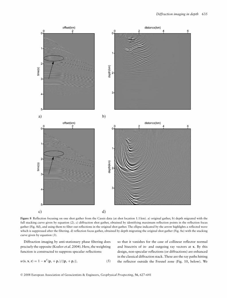
The procedure for removing specular reflections by re-flection focusing is illustrated on the Cassis data set inFigs 8 and 9. In Fig. 8(a) a single full-wave shot gather (at shotlocation 1.1km) is displayed, with a typical strong reflectionhighlighted by the ellipse. For reference, a partial Kirchhoffmigration of this gather is shown in Fig. 8(b). This image isobtained by applying the diffraction stack (1) with the stackingtrajectory (2) for the fixed source point. Figure 8(d) displays
the reflection focus gather for the same source point, obtainedby applying (1) with the stacking trajectory (3). In this im-age, the reflections are focused to sharp localized caustics. Themaxima of these caustics are localized by the scanning algo-rithm, consisting of a moving window, where the absolute en-ergy of the midpoint is checked against the absolute energy inall other points of the window. For maxima found by this scan-ning, the corresponding reflections in Figure 8a are filtered outby the moving window median filter. The resulting diffractionshot gather is displayed in Fig. 8(c) (note that the flow ofcomputations follows Figs 8a → 8d → 8c). Comparison withFig. 8(a) shows that important reflections, for example the onehighlighted by the ellipse, have been removed or suppressed.Repeating this for all shot gathers, and inserting the result-ing diffraction shot gathers into the diffraction stack (1), withthe normal stacking trajectory (2), yields the diffraction imagedisplayed in Fig. 9. We note that we have not attempted thefocusing of deeper reflections in these tests. As a result, thedeeper reflections (below 2km depth) have not been filteredout in Fig. 9. For the upper part of the section however (above2km depth), the reflection energy has been suppressed and thediffractors stand out.
Removing specular reflections usingan anti-stationary phase filter
Stationary-phase migration (Bleistein 1987; Schleicher et al.1997; Chen 2004) aims at emphasizing contributions to themigrated image from specular ray reflections. The main objec-tive is to reduce aliasing effects in the migrated image. Empha-sizing specular ray reflections is done by limiting the migra-tion aperture to the Fresnel zone around the specular reflectionpoint. This can be implemented by the weight function w(s, x,r) in the classical diffraction stack (1). For given ray vectorsps = ∇xT(s, x) and pr = ∇xT(r, x) from the source andreceiver, respectively, and a local unit normal vector tothe reflector n, the weight function can be designed asfollows:
w(s, x, r) = nT(ps + pr )/||ps + pr ||. (4)
which is the inner product of the reflector unit normal andthe bisectrix of the in- and outgoing ray vectors at x. Theweighting function defined by (4) attains its maximum whenthe reflector normal and the bisectrix are collinear, which isprecisely the case of specular ray reflection. The Fresnel zonearound the specular reflection point can be defined as w(x,s, r) > 1 − ε, where ε is a small number, which is frequencydependent. This is illustrated in Fig. 10 (above).
C© 2008 European Association of Geoscientists & Engineers, Geophysical Prospecting, 56, 627–641
Diffraction imaging in depth 635
Figure 8 Reflection focusing on one shot gather from the Cassis data (at shot location 1.1 km). a) original gather, b) depth migrated with thefull stacking curve given by equation (2). c) diffraction shot gather, obtained by identifying maximum reflection points in the reflection focusgather (Fig. 8d), and using them to filter out reflections in the original shot gather. The ellipse indicated by the arrow highlights a reflected wavewhich is suppressed after the filtering. d) reflection focus gather, obtained by depth migrating the original shot gather (Fig. 8a) with the stackingcurve given by equation (3).
Diffraction imaging by anti-stationary phase filtering doesprecisely the opposite (Kozlov et al. 2004). Here, the weightingfunction is constructed to suppress specular reflections:
w(s, x, r) = 1 − nT(ps + pr )/||ps + pr ||, (5)
so that it vanishes for the case of collinear reflector normaland bisectrix of in- and outgoing ray vectors at x. By thisdesign, non-specular reflections (or diffractions) are enhancedin the classical diffraction stack. These are the ray paths hittingthe reflector outside the Fresnel zone (Fig. 10, below). We
C© 2008 European Association of Geoscientists & Engineers, Geophysical Prospecting, 56, 627–641

636 T. J. Moser and C.B. Howard
Figure 9 Diffracted wave prestack-depth migration image, using diffraction shot gathers obtained by reflection focusing and filtering (seeFig. 8). Note that the reflectors in the bottom half of the image have not been suppressed, because the algorithm was applied here using only theavailable depth velocity model (Fig. 5a), without the required extrapolation to twice the depth range.
refer to the weight function (5) as the anti-stationary phase
filter.Some implementation details of diffraction imaging by anti-
stationary phase filtering are as follows. First, a reflector dipfield needs to be constructed for each image point x. There areseveral approaches to obtain reflector dips from a full-waveimage (Tygel et al. 1993; Fomel 2002; Marfurt 2006). Here,we apply a simple approach of a local slant stack, by searchingfor a local plane segment through x with maximal semblancein the full-wave image. Second, the ray vectors ps and pr canbe obtained by differentiating the corresponding travel-timefields, or by paraxial ray tracing. Third, the weight function (5)is moderated by a monotonic gain function (i.e. a power gain),which controls the amount of reflectivity to be suppressed.For simplicity, it is assumed that n and −n represent the samereflector dip, by taking the absolute value (or an even power)of the inner product in (5). Finally, the classical diffractionstack (1) is carried out with full-wave data as input, but withthe moderated weight function.
We illustrate the procedure of removing specular reflec-tions by reflection focusing on the Cassis data set in Figs 11and 12. Figure 11 shows the horizontal and vertical compo-nents of the reflector normal field (representing the dip), ob-tained from the full-wave pre-stack depth migrated image ofFig. 6, by the local slant-stack procedure (which consists offinding, at each image point, the dip with maximum sem-blance over a local plane segment among a relevant rangeof dips). Since most reflectors are horizontally oriented, the
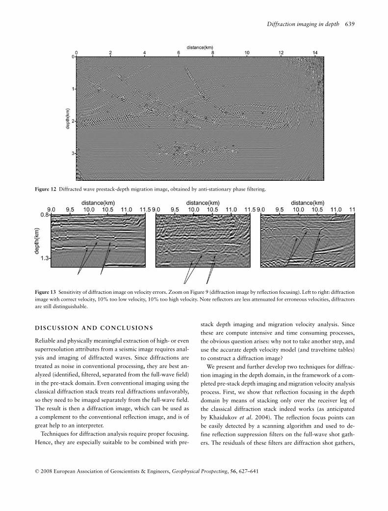
horizontal reflector normal component is close to zero, andthe vertical component close to one; at the reflector and faultjunctions, the normals are variable and less well defined (lowermaximum semblance). Figure 12 shows the diffraction image,obtained by applying the diffraction stack (1) with the con-ventional stacking trajectories (2), but the modified migrationkernel, given by equation (5). Note that reflector energy hasbeen removed or suppressed here over the full depth range ofthe image, with some residuals remaining in the deeper part(due to fixed filter settings over the depth range).
Sensitivity to velocity errors
The main argument of this paper is that as soon as a high-quality full-wave pre-stack depth migration and correspond-ing migration velocity analysis have been completed, the samevelocity information can be used advantageously for diffrac-tion imaging. However, the implications of an erroneous ve-locity on diffraction imaging remain an important issue. Onequestion is whether the diffraction image is as sensitive tovelocity errors as the full-wave image. Another question iswhich phenomenon is likely to occur first, when the velocitybecomes increasingly erroneous: the appearance of migrationartifacts for full-wave imaging, illustrated and discussed inFig. 1(d), or the defocusing of diffracted images. If diffractedimages can be shown to be stable and detectable for a signifi-cant range of velocity deviations, that would argue in favor ofdiffraction imaging. In any case, a migration artifact due to an
C© 2008 European Association of Geoscientists & Engineers, Geophysical Prospecting, 56, 627–641

Diffraction imaging in depth 637
Figure 10 Schematic illustration of the principle of anti-stationaryphase filtering. Top: conventional stationary phase migration usesonly (specular) reflections within a Fresnel zone around the reflectionpoint. Bottom: diffraction imaging using the anti-stationary phase fil-ter uses only non-specular responses from the reflector outside theFresnel zone.
erroneously focused syncline can be distinguished from a de-focused diffracting edge (Fig. 1d, at distance 1 km and 2–3 km,respectively) by using additional amplitude and phase prop-erty information of diffractions (as we point out at the end ofthe section ‘Image resolution and diffractions’). Additionally,if common-image gathers are constructed for diffraction imag-ing (the same way they are constructed for full-wave imaging),then a defocused diffractor image will appear with a certainmove-out; a diffraction residual move-out may then improvethe focusing.
To examine the effect of an erroneous velocity on diffrac-tion imaging, we show in Fig. 13 the results of the reflection-focusing technique (where velocity is more critical than in theanti-stationary phase technique) with three different veloci-ties: the correct velocity, a 10% too low, and a 10% too highvelocity. As expected, for the too low velocity the image isshifted downward and the diffractors become smiles, for thetoo high velocity they become frowns. In both cases, the re-
flectors are less well attenuated, but still the diffractors can beclearly distinguished.
A P P L I C AT I O N S
Diffraction imaging has a wide range of applications and po-tential applications: ground-penetrating radar (GPR) imaging(Grasmueck and Weger 2005), environmental studies (Shtivel-man and Keydar 2004), archeology, and others. We elaboratehere in some detail on the potential of using diffractions inhigh-quality reservoir imaging. Small scale faults may affectreservoir flow properties very strongly and so identifying andpositioning these may be critical in developing a representa-tive reservoir model and hence to the chosen developmentscenario. Since the identification of small scale fractures onreflection seismic generally depends upon identifying beddingdisplacements (fault surfaces are generally poor reflectors fora standard acquisition geometry), we can only see fractureswhere the seismic resolution allows. Faults with small dis-placement or joints may not be resolved, and tracing a fault asthe throw decreases, for example when it enters a relay zone,may be unreliable. Diffraction imaging attempts to remove thespecular reflections arising from the bedding planes and leavesonly the diffractions arising from the rough fault surfaces orfrom within fault zones. The magnitude of these diffractions isnot controlled by fault displacement, but more by the rough-ness of the fault surface and the contrast of impedance be-tween the fault zone content and the surrounding beds. Thisimplies that we could theoretically trace a fracture even whenthere is zero displacement (that is, beyond Rayleigh’s reso-lution criterion). Constructing a static model of a (faulted)reservoir usually starts with building a fault framework andthen, when this is complete, attaching the bedding geome-try. The diffraction image will be useful to help build thisfault framework, perhaps as a combined display with the re-flection image, resulting in a fault model with better definedfault planes and fault zones, even when fault displacementsare low. Also, fractures due to differential stress, on the crestof an anticline for example, would be more easily identifiedusing diffraction imaging. Stratigraphic traps rely on the po-sition of pinch-outs of sediment geometries either due to afacies change or an erosional truncation. Because of the reso-lution of seismic data, to assign the position of a pinch-outthe interpreter has to extrapolate an interpretation of twobedding surfaces (or one bedding and one erosional surface)until they intersect. Because of the low angles, and the inher-ently rough nature of geological bedding surfaces, the positionerror may be very large. Diffraction imaging could be used
C© 2008 European Association of Geoscientists & Engineers, Geophysical Prospecting, 56, 627–641

638 T. J. Moser and C.B. Howard
Figure 11 Dip field obtained from the full-wave prestack-depth migration image by a local slant-stack approach: a) horizontal component ofreflector normal, b) vertical component.
to identify changes in roughness of an interface, and henceindicate the positions of pinch-outs and construct sub-cropmaps at unconformities.
As an illustration, we highlight a few features in the diffrac-tion image of Fig. 12. First, pinch-outs are imaged very sharplyat several locations. Figure 14(a) shows a zoom on a pinch-outat distance 2.3 km and depth 2.2 km. In the full-wave imageit is hardly distinguishable and very difficult to localize. Bycontrast, in the diffraction image it is easily detectable as thelast diffraction cross along the upper pinching reflector. Infact, one may be tempted to label this case as superresolutionimaging, at least indirectly. The location of the pinch-out con-stitutes information that is not available in the full-wave im-age, because of the overlapping of the band-limited images ofthe two reflectors approaching each other (from right to left).The fact that the diffraction image does allow to accuratelylocate the pinch-out would imply imaging to sub-wavelength
scale, and therefore beyond the Rayleigh limit. Figure 14(b)shows a zoom on the main fault system from distance 6.5 kmto 8 km. Here the fault junctions with the horizontally orientedreflectors are much more prominent in the diffraction imagethan in the full-wave image. The third example, displayed inFig. 14(c), illustrates diffraction imaging on so-called roughhorizons, i.e., reflectors with many small-scale discontinuitiesand other diffracting elements. In this case, the discontinuitiesare caused by a grid representation of the velocity model usedin generating the synthetic data. Nevertheless, the fact thatthese grid edges are accurately imaged in the diffraction imageshows the power of the diffraction imaging method (even tothe extent that the grid diffractors can be counted and the orig-inal grid size may be reconstructed). Phase characteristics ofthe imaged diffractors provide additional structural informa-tion on the orientation of the small-scale discontinuities andthe sign of the impedance contrasts.
C© 2008 European Association of Geoscientists & Engineers, Geophysical Prospecting, 56, 627–641
Diffraction imaging in depth 639
Figure 12 Diffracted wave prestack-depth migration image, obtained by anti-stationary phase filtering.
Figure 13 Sensitivity of diffraction image on velocity errors. Zoom on Figure 9 (diffraction image by reflection focusing). Left to right: diffractionimage with correct velocity, 10% too low velocity, 10% too high velocity. Note reflectors are less attenuated for erroneous velocities, diffractorsare still distinguishable.
D I S C U S S I O N A N D C O N C L U S I O N S
Reliable and physically meaningful extraction of high- or evensuperresolution attributes from a seismic image requires anal-ysis and imaging of diffracted waves. Since diffractions aretreated as noise in conventional processing, they are best an-alyzed (identified, filtered, separated from the full-wave field)in the pre-stack domain. Even conventional imaging using theclassical diffraction stack treats real diffractions unfavorably,so they need to be imaged separately from the full-wave field.The result is then a diffraction image, which can be used asa complement to the conventional reflection image, and is ofgreat help to an interpreter.
Techniques for diffraction analysis require proper focusing.Hence, they are especially suitable to be combined with pre-
stack depth imaging and migration velocity analysis. Sincethese are compute intensive and time consuming processes,the obvious question arises: why not to take another step, anduse the accurate depth velocity model (and traveltime tables)to construct a diffraction image?
We present and further develop two techniques for diffrac-tion imaging in the depth domain, in the framework of a com-pleted pre-stack depth imaging and migration velocity analysisprocess. First, we show that reflection focusing in the depthdomain by means of stacking only over the receiver leg ofthe classical diffraction stack indeed works (as anticipatedby Khaidukov et al. 2004). The reflection focus points canbe easily detected by a scanning algorithm and used to de-fine reflection suppression filters on the full-wave shot gath-ers. The residuals of these filters are diffraction shot gathers,
C© 2008 European Association of Geoscientists & Engineers, Geophysical Prospecting, 56, 627–641

640 T. J. Moser and C.B. Howard
Figure 14 Examples of diffraction imaging. Left column: zooms on full-wave image of Fig. 6; right column: zooms on Fig. 12 (diffraction imageby anti-stationary phase filtering). a) pinch-out example. Pinch-out indicated by the “H”-symbol. Note that the diffraction image allows a veryprecise localization of the pinch-out being the last diffraction along the pinching reflector. Since this degree of detail is lost in the full-wave imagewe may speak of (indirect) superresolution. b) fault example. The fault stands more out in the diffraction image. c) rough horizon example.Here the rough horizon is imaged properly in the full-wave image, but its roughness is much easier to interpret in the diffraction image. Alsonote phase rotations (in black and white) in the diffraction image, corresponding to the impedance contrast across the diffractors.
and diffraction imaging consists in imaging them separatelyfrom the full-wave. Diffraction imaging by reflection focus-ing requires a velocity model with a much larger depth rangethan the full-wave imaging, typically twice as deep. The sec-ond method reverses the stationary-phase principle to enhancediffractions (non-specular scattering) and suppress reflections(specular scattering). This method requires a reflector dip fieldto be extracted from the full-wave image. By modifying theweighting function in the migration kernel in such a way that
specular ray reflections are suppressed, or, equivalently, allscattering within the first Fresnel zone, we obtain an anti-stationary phase filter. Diffraction imaging by anti-stationaryphase filtering consists then in applying the classical diffrac-tion stack with the modified migration kernel.
We note that for both methods we assume a sufficiently ac-curate velocity model, that is, a model which is sufficient toenable an optimally focused full-wave pre-stack depth image.We do not discuss in this paper any mechanism for additional
C© 2008 European Association of Geoscientists & Engineers, Geophysical Prospecting, 56, 627–641

Diffraction imaging in depth 641
focusing. As such, the methods presented here do not them-selves allow to unmask the migration artifacts, which are theresult of an inadequate migration depth velocity model. Suchartifacts need to be analyzed by additional pre-stack diffrac-tion analysis tools. However, the pre-stack depth diffractionimaging allows to construct common-image gathers, whereresidual move-out may be used to improve the diffraction fo-cusing. Such diffraction residual move-out analysis is a topicof ongoing research.
We did not investigate the effect on diffraction imaging ofa low signal-to-noise ratio in the pre-stack data. A high noiselevel compromises the quality of the reflection suppression fil-tering based on reflection focusing, and also the extractionof a reflector dip field for anti-stationary phase filtering. Wewould expect noise to be equally detrimental to both diffrac-tion imaging processes as it is to full-wave pre-stack imaging.
Diffraction imaging can be of great help to an interpreter.Many structural features, such as small-scale faults and pinch-outs, are much easier to localize, identify and characterize onthe diffraction images. In several such cases, we may be eventempted to label the images as superresolution images. Weintend to carry out a number of case studies on real productiondata to further the case of diffraction imaging.
A C K N O W L E D G E M E N T S
The authors appreciate discussions with Evgeny Landa andShmoriahu Keydar. We are also grateful to Opera (Pau), formaking the ‘Cassis’ data set available for tests.
R E F E R E N C E S
Bansal R. and Imhof M.G. 2005. Diffraction enhancement in prestackseismic data. Geophysics 70, V73–V79.
Biondi B. 2006. 3D Seismic Imaging. SEG, Investigations in Geo-physics, 14.
Bleistein N. 1987. On the imaging of reflectors in the earth. Geo-physics 52, 931–942.
Chen J. 2004. Specular ray parameter extraction and stationary-phasemigration. Geophysics 69, 249–265.
Fehmers G.C. and Hockers C. 2003. Fast structural interpretationwith structure-oriented filtering. Geophysics 68, 1286–1293.
Fomel S. 2002. Applications of plane-wave destruction filters. Geo-physics 67, 1946–1960.
Fomel S., Landa E. and Taner M.T. 2006. Post-stack velocity analysisby separation and imaging of seismic diffractions, 76th SEG meet-ing, New Orleans, Louisiana, USA, Expanded Abstracts, 2559–2563.
Gersztenkorn A. and Marfurt K.J. 1999. Eigenstructure-based coher-ence computations as an aid to 3-D structural and stratigraphicmapping. Geophysics 64, 1468–1479.
Grasmueck M. and Weger R. 2005. Full-resolution 3D GPR imaging.Geophysics 70, K12–K19.
Hubral P., Schleicher J. and Tygel M. 1996. A unified approach to3-D seismic reflection imaging, Part I: Basic concepts. Geophysics61, 742–758.
Khaidukov V., Landa E. and Moser T.J. 2004. Diffraction imaging byfocusing-defocusing: An outlook on seismic superresolution. Geo-physics 69, 1478–1490.
Klem-Musatov K. 1994. Theory of Seismic Diffractions. SEG, Tulsa.Kozlov E., Barasky N., Koroloev E., Antonenko A. and Koshchuk
E. 2004. Imaging scattering objects masked by specular reflections,74th SEG meeting, Denver, Colorado, USA, Expanded Abstracts,1131–1135.
Liu J. and Marfurt K.J. 2007. Instantaneous spectral attributes todetect channels. Geophysics 72, P23–P31.
Marfurt K.J. 2006. Robust estimates of 3D reflector dip and azimuth.Geophysics 71, P29–P40.
Marfurt K.J., Kirlin R.L., Farmer S.L. and Bahorich M.S. 1998.3-D seismic attributes using a semblance-based coherency algo-rithm. Geophysics 63, 1150–1165.
Sava P., Biondi B. and Etgen J. 2004. Diffraction-focusing migrationvelocity analysis, 74th SEG meeting, Denver, Colorado, USA, Ex-panded Abstracts, 2395–2399.
Schleicher J., Hubral P., Tygel M. and Jaya M.S. 1997. Minimum aper-tures and Fresnel zones in migration and demigration. Geophysics62, 183–194.
Shtivelman V. and Keydar S. 2004. Imaging shallow subsurface in-homogeneities by 3D multipath diffraction summation. First Break23, 39–42.
Taner M.T., Fomel S. and Landa E. 2006. Separation and imagingof seismic diffractions using plane-wave decomposition, 76th SEGmeeting, New Orleans, Louisiana, USA, Expanded Abstracts, 2401.
Timoshin Y.V. 1978. Seismic Pulse Holography. Nedra (in Russian).Tygel M., Schleicher J., Hubral P. and Hanitzsch C. 1993. Multiple
weights in diffraction stack migration. Geophysics 59, 1820–1830.
C© 2008 European Association of Geoscientists & Engineers, Geophysical Prospecting, 56, 627–641