differential settlement and its importance ondifferential
TRANSCRIPT

Differential Settlement and its Importance onDifferential Settlement and its Importance on the Performance of Cover Systems at Radiological Waste Disposal Facilities
Robert C. Bachus, John F. Beech, and Leslie M. GriffinGeosyntec Consultants
Kennesaw GAKennesaw, GA
Workshop on Engineered Barrier Performance Related to Low-Level Radioactive Waste, Decommissioning, and Uranium Mill Tailings Facilities
R k ill MDRockville, MD4 August 2010
WorkshoppEngineered Barrier Performance Related to Low-Level Radioactive Waste, Decommissioning, and
U i Mill T ili F ilitiUranium Mill Tailings Facilities
Session 3Session 3Experience with Monitoring Devices and Systems
Used to Measure Performance
Presentationff SDifferential Settlement and its Importance on the
Performance of Cover Systems at Radiological Waste Disposal Facilitiesp

Differential Settlement and its Importance on the Performance of Cover Systems at Radiological e o a ce o Co e Syste s at ad o og ca
Waste Disposal Facilities
E i d C S t• Engineered Cover Systems– Components– Soils and Geosynthetic Material Characteristics
• Differential Settlement– Settlement Mechanisms– DOE-specific Issuesp
• Monitoring Devices and Systems– Types of Devices and Systems– Experience– Experience
• Recommendations for DOE Facilities– Monitoring and Reporting
R h bilit ti– Rehabilitation
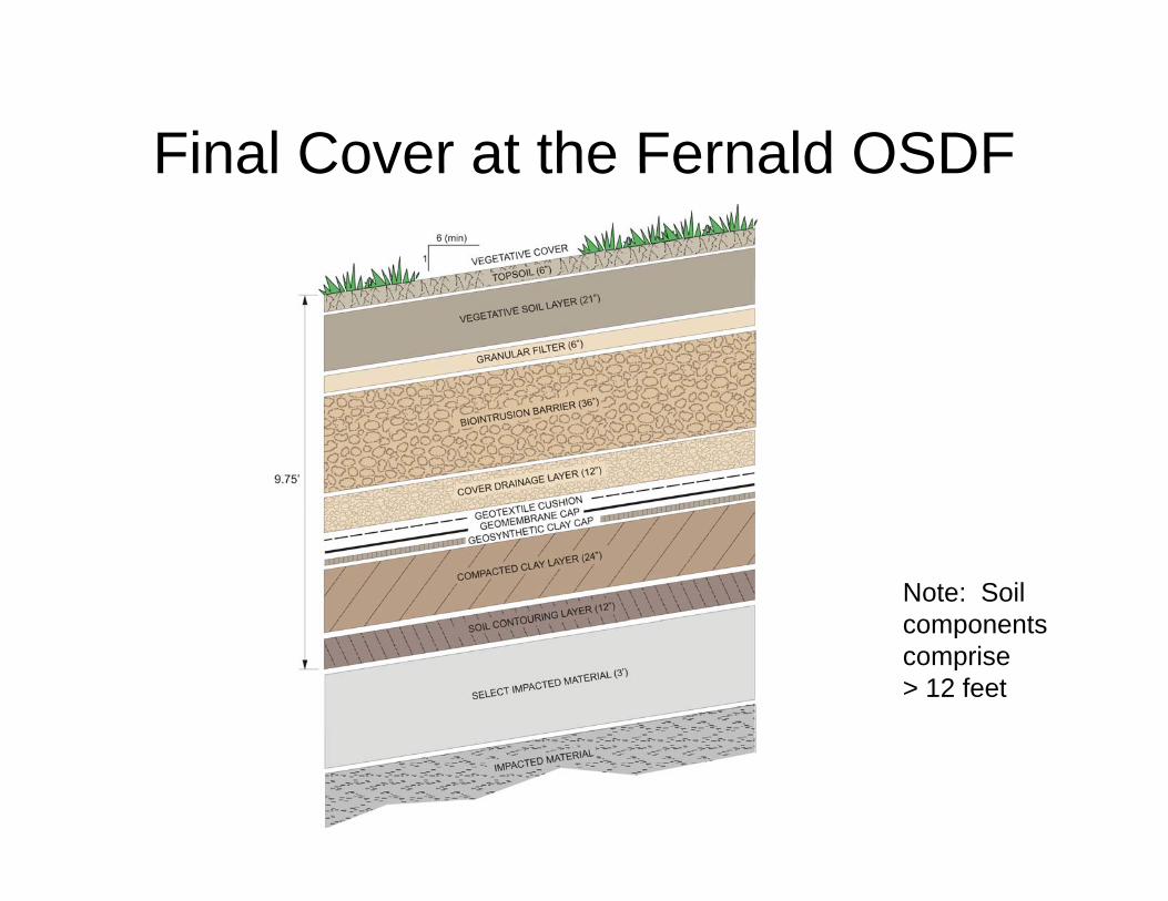
Final Cover at the Fernald OSDFFinal Cover at the Fernald OSDF
Note: Soilcomponentscomponents comprise> 12 feet
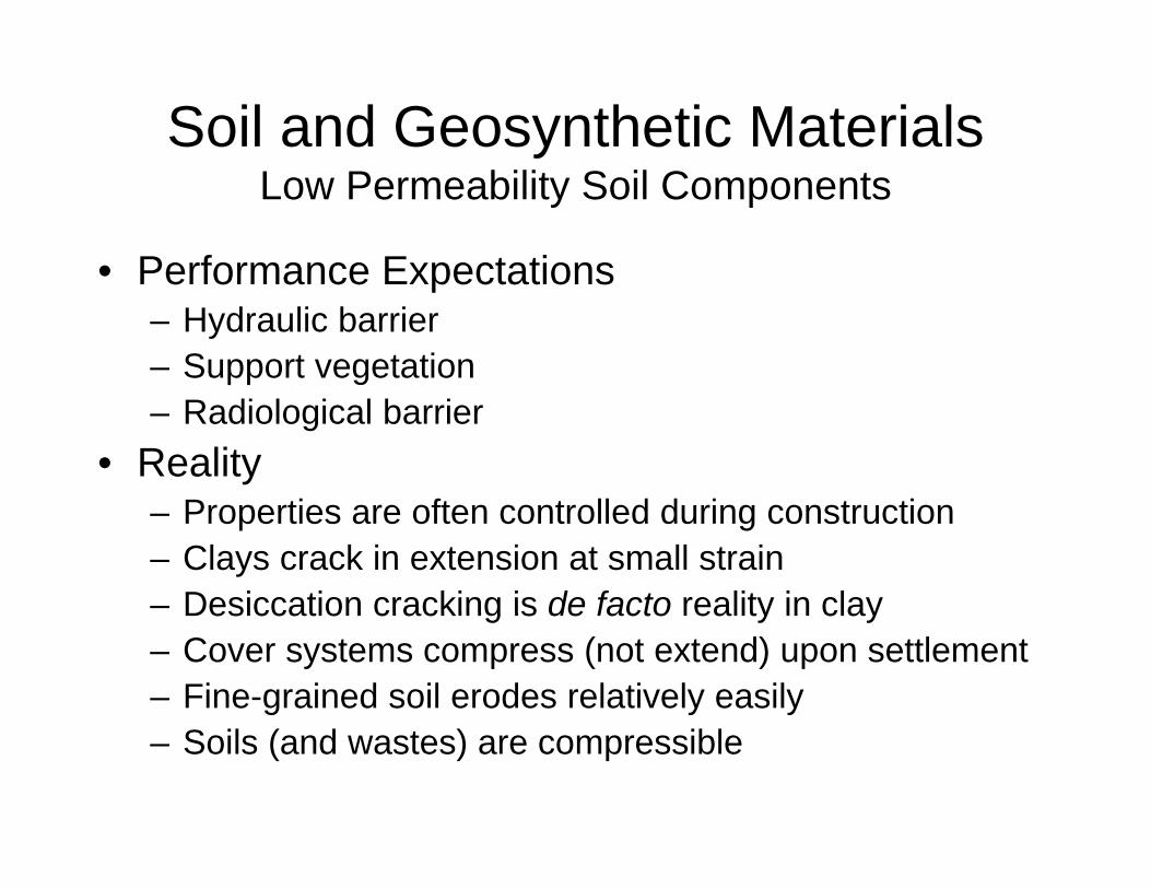
Soil and Geosynthetic MaterialsLow Permeability Soil Components
• Performance ExpectationsPerformance Expectations– Hydraulic barrier– Support vegetation– Radiological barrier
• RealityP ti ft t ll d d i t ti– Properties are often controlled during construction
– Clays crack in extension at small strain– Desiccation cracking is de facto reality in clayDesiccation cracking is de facto reality in clay– Cover systems compress (not extend) upon settlement– Fine-grained soil erodes relatively easily– Soils (and wastes) are compressible

Waste CompressibilityWaste Compressibility• Mechanisms of waste compression that can lead p
to total and differential settlement– Mechanical Compression – compression of soil and
waste due to loadingg– Raveling – Internal erosion of soil due to water and/or
migration of soil due to large voids– Physico-chemical Changes – degradation of wastePhysico chemical Changes degradation of waste
and subsequent mass loss– Biomechanical Changes – biological decomposition of
wasteas e• Waste (and surrounding soil) compression leads
to total and differential settlement

Waste Settlement and Differential Settlement(admittedly worst case)(admittedly worst case)
– Settlement is not uniform because waste maySettlement is not uniform because waste may not be uniform
– Therefore, localized subsidence and ,differential settlement can occur

Waste may not be uniform

Often Includes (Temporarily) Stiff InclusionsOften Includes (Temporarily) Stiff Inclusions

DOE-Related IssuesDOE Related Issues
• Extreme conditions as shown on previousExtreme conditions as shown on previous slides may be just that…extreme examplesp– Old facilities – Uncontrolled trench disposal practices – Compromised covers and raveling conditions
• Can likely be controlled at new facilitiesy– Monitored waste placement– Waste placement plans

Concept of Stress RedistributionConcept of Stress Redistribution
Average Stress Actual Stressg
SOFT SOFTHARD HARD
Mother Nature does not like abrupt changes in material properties and will redistribute stress in direct response to materials stiffness
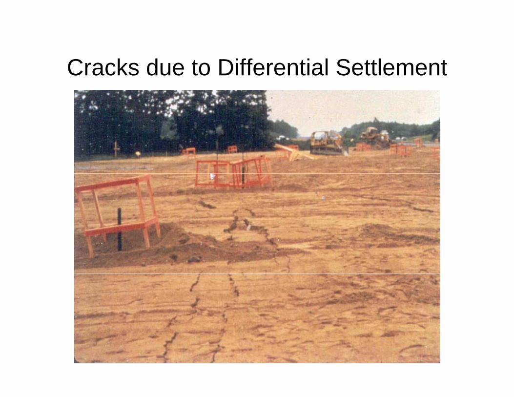
Cracks due to Differential SettlementCracks due to Differential Settlement

Waste Compressibility for DOEWaste Compressibility for DOE
• Mechanisms of waste compression thatMechanisms of waste compression that can lead to total and differential settlement– Mechanical compression – likely for DOEp y– Raveling – problematic for old DOE facilities– Physico-chemical changes – not likelyy g y– Biomechanical changes – not likely
• For DOE facilities, may have different , yconcerns and mechanisms when considering old versus new facilities

Performance Aspects of Cover System Components
Support Vegetation
PROTECTIVE SOIL LAYER
(24 INCH THICK)
Support Vegetation
Drainage
1 8 INC H SO IL B ARRI ERGEOC OMP OSIT ED RAIN AGE LAYE RPE GEO MEM BRAN E(40 MIL THIC K)
4 to 2 01
2 4 INC H PR OTE CTIV E SOI L LAY ER
12 INCH INT ERME DIAT E SO IL CO VER /
ST RUCT URA L FIL L
BARRIER
GEOCOMPOSITEDRAINAGE LAYER Low Permeability
Soil and Geomembrane
SOIL BARR
(18 INCH THICK)
PE GEOMEMBRANE(40 MIL THICK)
IATE SOIL COVER/
CH THICK)Isolation
R i f t
4 to 201 INTERMEDIATE S
STRUCTURAL FILL (12 INCH TH
Example
Reinforcement(optional)
20
ExampleUSEPA Subtitle D
Final Cover System

Properties and MeasurementsProperties and Measurements• How to Assess Propertiesp
– Laboratory tests– Performance monitoring and back calculation– Monitored large test fill– Monitored large test fill
• Candidate Field Monitoring Concepts/Devices– Visual inspection– Aerial survey– Settlement plates– Buried settlement platesBuried settlement plates– Hydraulic sensors– Instrumented geotextiles
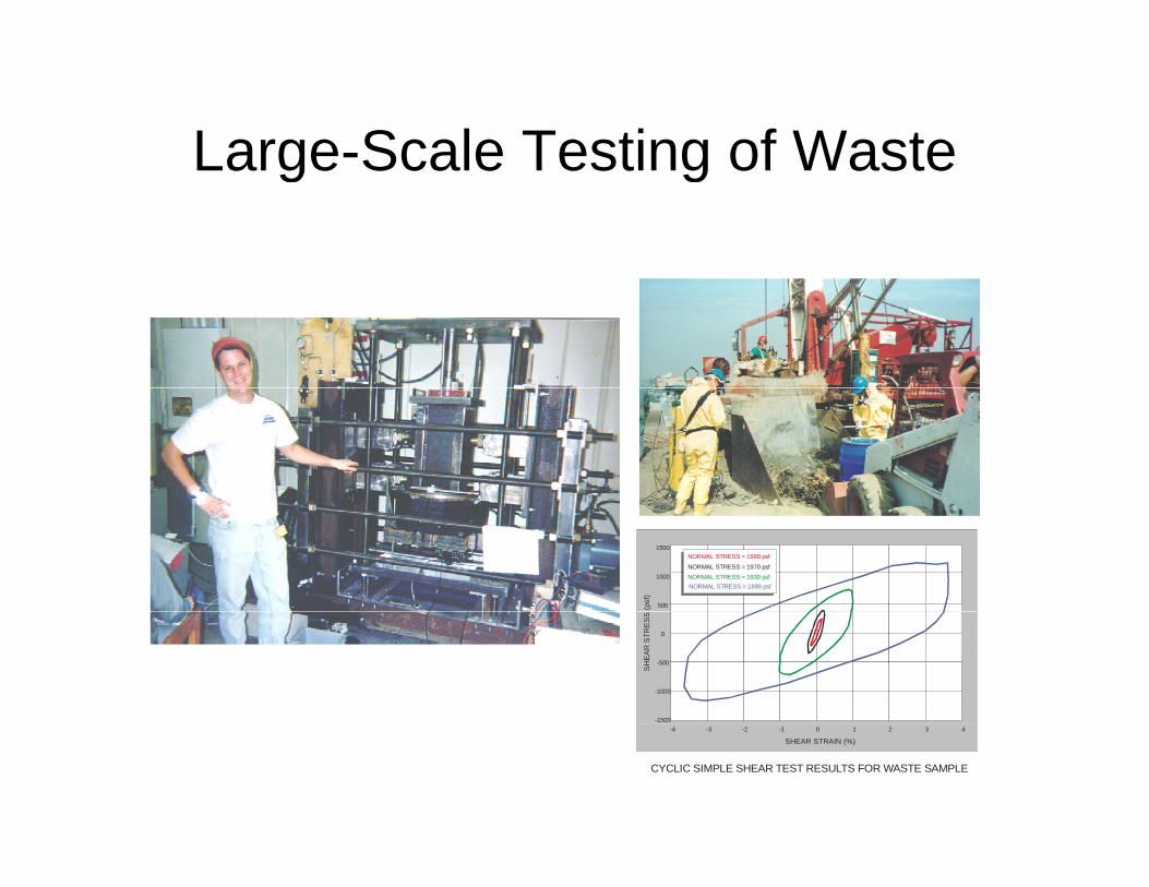
Large-Scale Testing of WasteLarge Scale Testing of Waste
1500
500
1000
(psf
)
NORMAL STRESS = 1930 psfNORMAL STRESS = 1970 psf
NORMAL STRESS = 1980 psf
NORMAL STRESS = 1890 psf
-1500
-500
-1000
0
SH
EA
R S
TRE
SS
CYCLIC SIMPLE SHEAR TEST RESULTS FOR WASTE SAMPLE
-4 -3 -2 -1 0 1 2 3 4
SHEAR STRAIN (%)

Waste Compressibility
Primary Compression (C C )
p y(mechanical… but with time can be physico-chemical and biological)
Primary Compression (Cc, Cr)
C
nV
Cc
CrMaximum Preconsolidation
Stress = p’c
v
Secondary Compression (C)log n
vC
Initial&
PrimarySecondary
Log Time
C

Monitoring DevicesMonitoring Devices
• Visual inspectionVisual inspection– Probably best for DOE– Evidence of erosion and “bowl shapes”p
• Aerial survey– Excellent, except for resolution– Provides general assessment
• Settlement plates and surface monitoring points– Best, low-cost solution– Need to be where there is movement!

Riser Pipe and Surface Settlement PlPlate

Monitoring DevicesMonitoring Devices
• Buried settlement platesBuried settlement plates– Can help assess variations with depth– Help assess effects of ageHelp assess effects of age
• Hydraulic sensors– Good for automated monitoringGood for automated monitoring– Good for “profiling”
• Instrumented geotextilesInstrumented geotextiles– May be helpful in long-term study– Potential for automated profilingPotential for automated profiling

Instrumented Test Fill - MSWInstrumented Test Fill MSW
• Vertical and Lateral Expansion of South Shelby• Vertical and Lateral Expansion of South Shelby Landfill, Memphis, TN
• New Waste Placement Causes Considerable Settlements of OldSettlements of Old (Unlined) Waste
• Analogous to DOE placement of thick cover over existing waste

3D View of Test Fill3D View of Test Fill
20 foot platform
30-foot platform
10-foot platform
20-foot platform
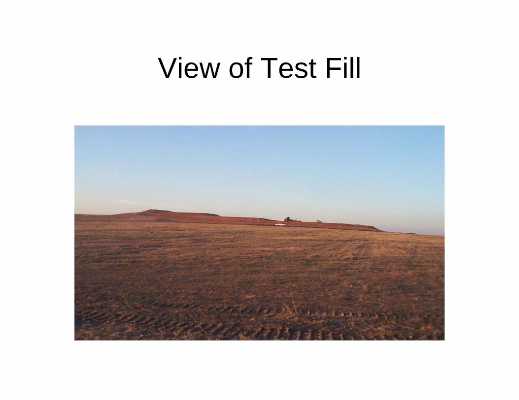
View of Test FillView of Test Fill
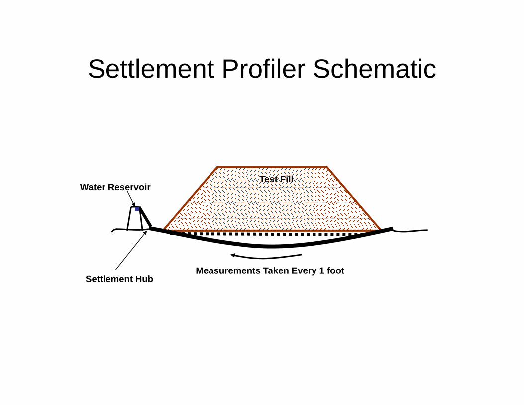
Settlement Profiler SchematicSettlement Profiler Schematic
T t FillTest FillWater Reservoir
Settlement HubMeasurements Taken Every 1 foot
Settlement Hub
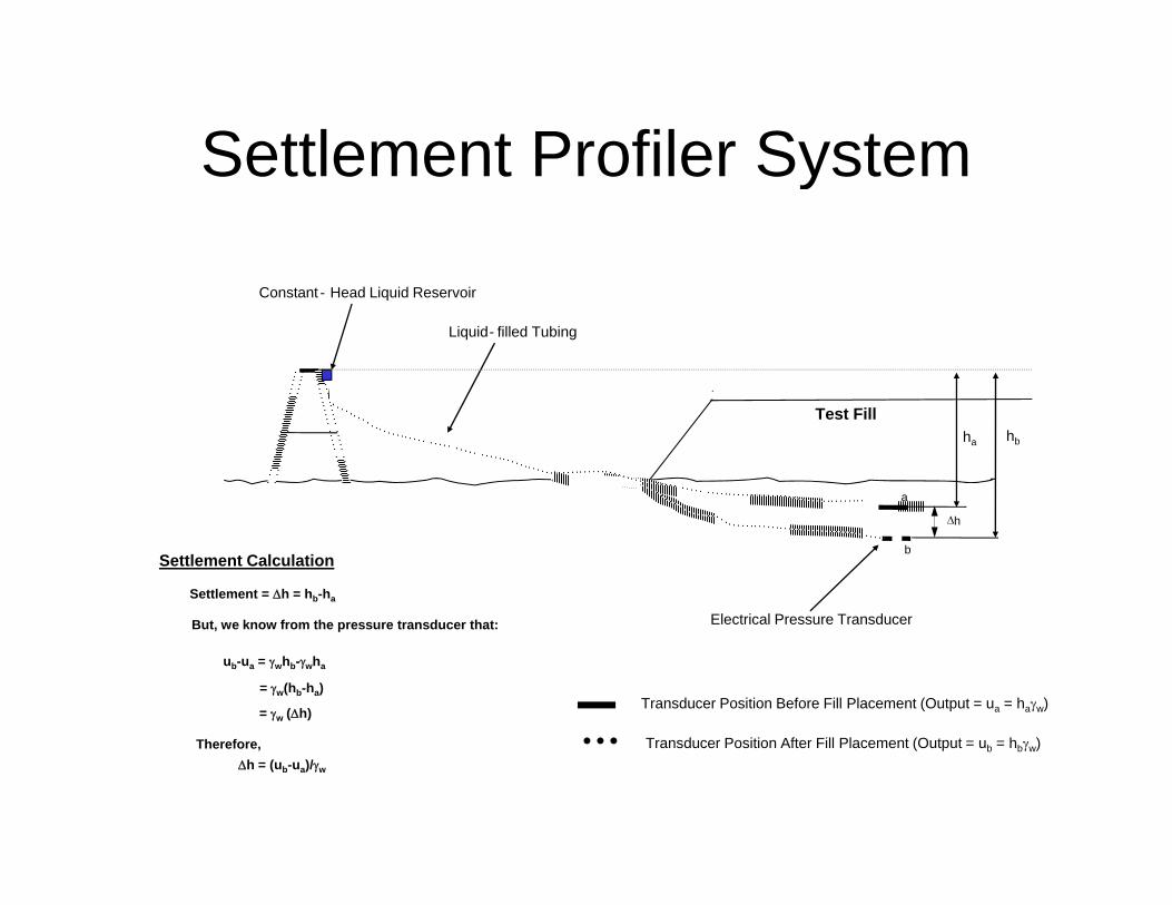
Settlement Profiler SystemSettlement Profiler System
Constant - Head Liquid Reservoir
Liquid- filled Tubing
Test Fill
a
ha hb
Settlement Calculation
Settlement = h = hb-ha
But we know from the pressure transducer that:
b
h
Electrical Pressure TransducerBut, we know from the pressure transducer that:
ub-ua = whb-wha
= w(hb-ha)
= w (h)
Electrical Pressure Transducer
Transducer Position Before Fill Placement (Output = ua = haw)
T d P iti Aft Fill Pl t (O t t h )h = (ub-ua)/w
Therefore, Transducer Position After Fill Placement (Output = ub = hbw)

Longitudinal Cross-SectionLongitudinal Cross Section
Test Fill Soil10’
20’30’
Existing Waste
Settlement Profile Pipe
Foundation Soils (thickness ~1000 ft)
Bedrock
Deep Settlement Plate
Surface Settlement Plate
(Not to Scale)

Surface Settlement PlateSurface Settlement Plate
40
60
et)
20
40
Hei
ght (
fe End of Construction
-20
00 20 40 60 80 100 120 140
t) x
10
-40
tlem
ent (
feet
-60Time (days)
Set
t

Surface Settlement Plates
D
Surface Settlement Plates
00 25 50 75 100 125 150
Days
1
2
3ft)
FillHeight~ 11 feet
3
4
5Set
tlem
ent (
f
~22 feet
5
6
7
S
~ 31 feet
8
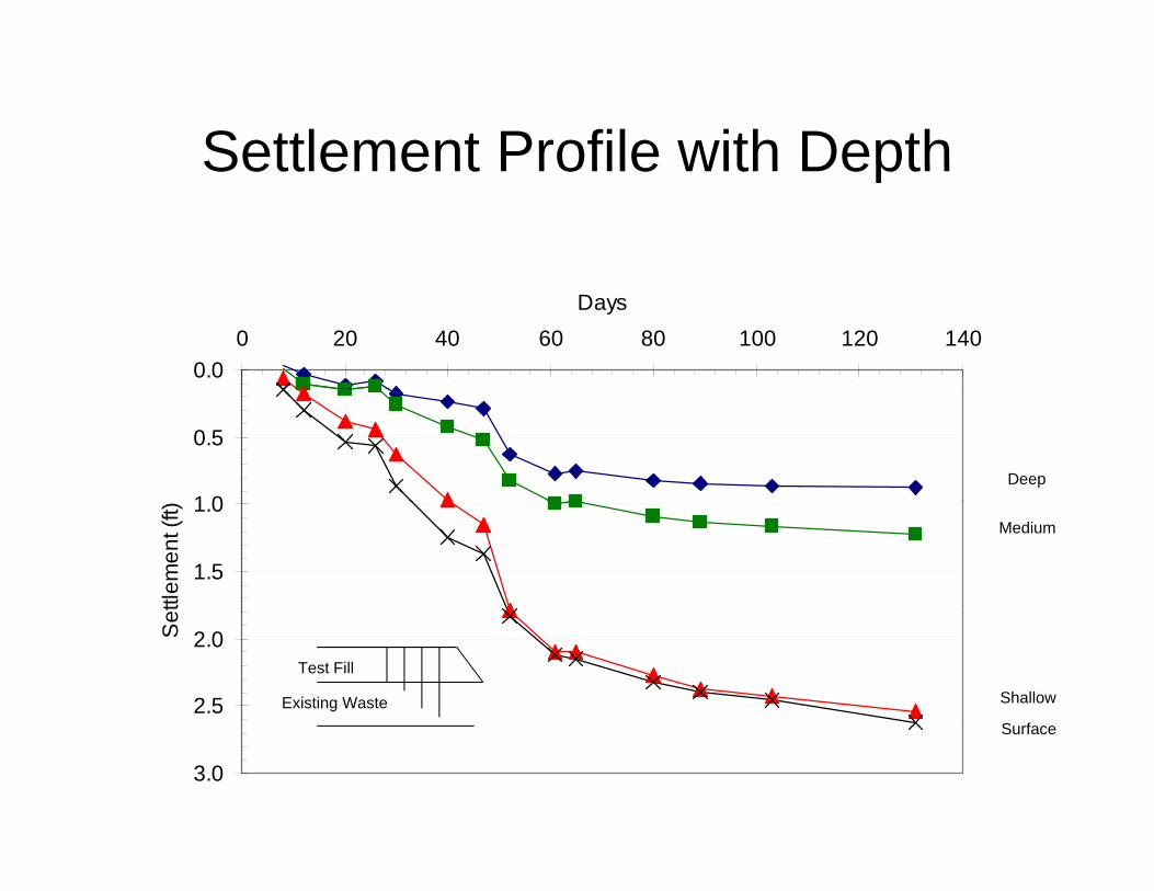
Settlement Profile with DepthSettlement Profile with Depth
0.00 20 40 60 80 100 120 140
Days
0.5
1 0Deep
1.0
1.5
ettle
men
t (ft)
Medium
2.0
2.5
Se
Test Fill
Existing Waste Shallow
Surface
3.0
Surface

Settlement Profiler ResultsSettlement Profiler Results445
430
435
440
Ele
vatio
n (ft
) 8-Dec-0028-Nov-0017-Nov-0027-Oct-00
415
420
425
0 100 200 300 400 500 600 700
Fill
23-Oct-0019-Oct-00
5
6
7
r Pip
e (ft
)
19-Oct-00
Distance along Pipe (ft)
-1
0
1
23
4
0 100 200 300 400 500 600 700ve E
leva
tion
of P
rofil
er
23-Oct-0027-Oct-0017-Nov-00
28-Nov-008-Dec-00
-3
-2
-1
Distance along Pipe (ft)
Rel
ative

Settlement Profiler Results
5
7
vatio
n (ft
)
1
3
Rel
ativ
e E
lev
5
(ft)
-10 100 200 300 400 500 600 700
Distance from Eastern Hub (ft)
-1012345
190 195 200 205 210elat
ive
Ele
vatio
n
-3-2
Distance from Eastern Hub (ft)
Re

Implications to DOE SitesImplications to DOE Sites
• In the absence of raveling and theIn the absence of raveling and the introduction of water, differential settlement is NOT a major problemj p
• Most of the settlement is due to application of load
• Time-dependent settlements are small and relatively uniformy
• Monitoring requirements are relatively simplep
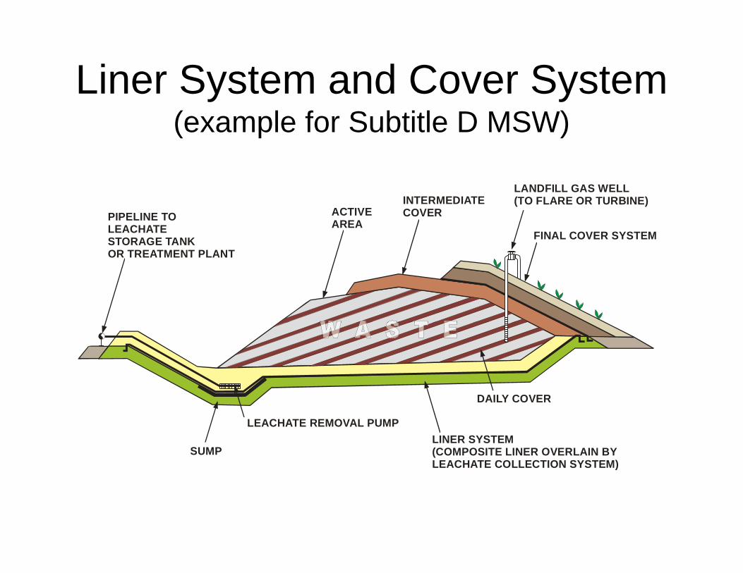
Liner System and Cover System (example for Subtitle D MSW)
PIPELINE TO LEACHATESTORAGE TANKOR TREATMENT PLANT
ACTIVEAREA
FINAL COVER SYSTEM
LANDFILL GAS WELL(TO FLARE OR TURBINE)INTERMEDIATE
COVER
OR TREATMENT PLANT
DAILY COVER
LEACHATE REMOVAL PUMP
SUMPLINER SYSTEM(COMPOSITE LINER OVERLAIN BYLEACHATE COLLECTION SYSTEM)
DAILY COVER
LEACHATE COLLECTION SYSTEM)

Leachate Generation Rates
300
350
400
WR
ATE
0
100
150
200
250
EAC
HAT
EFL
OW
MSW LANDFILL(PENNSYLVANIA)
Rainfall = 39 inches/years
RAINFALL
ACTIVEFILLING
COVER CELL CLOSED
0
50L
LEACHATETRANSFERPIPE
RAINFALLONTO ACTIVE AREA
LEACHATEGENERATION
LINER SYSTEMLEACHATE PUMPEDFROM SUMP
SUMP15

Generalized MSW Leachate Generalized MSW Leachate Generation Rates Generation Rates –– Rainfall FactorRainfall Factor
1000 – 2000 gpad(30 to 60% of rainfall)
300 – 600 gpad(10 to 20% of rainfall)
100 – 200 gpad(3 to 6% of rainfall)
20 – 40 gpad(0.6 to 1.2% of rainfall)
10 – 20 gpad(0.3 to 0.6% of rainfall)

Influence of Time after Closure on Influence of Time after Closure on L h t G ti R tL h t G ti R tLeachate Generation RateLeachate Generation Rate
HW LANDFILLS

RecommendationsRecommendations
• Monitor Performance of Existing FacilitiesMonitor Performance of Existing Facilities– Seems that “data” includes visual assessment – Limited quantitative dataq– Summary report of problems may exist
• Visual reportsS ttl t l t• Settlement plates
• Leachate generation rate
• Report FindingsReport Findings– Identify forum for presentation of monitoring results– Report performance of rehabilitation measures
Design Challenges and Solutions
Issue – Differential Settlements• Differential settlements along liner resulting from waste variability and local
ft h d t ( ll i id th “ t d f i t ”)soft or hard spots (e.g., collapsing void...the “rusted refrigerator”) may impair the liquid containment capability of the leachate collection system and/or cause localized settlements that result in the ponding of liquids or excessive liner system strain.
Solution• Assess actual site conditions to avoid “worst case” analyses. Incorporate
high stiffness geosynthetic reinforcement in the liner system or subbase g g y yand/or construct a foundation “buffer layer” between liner system and existing waste. Also, ground improvement techniques (e.g., deep dynamic compaction) can be used to minimize near-surface heterogeneities.
• Analytical procedures are available to select appropriate reinforcement• Analytical procedures are available to select appropriate reinforcement properties (e.g., strength, stiffness) or minimum thickness buffer layer.

Design Challenges and SolutionsDesign Challenges and Solutions“Rusted Refrigerator” Scenario
SURFACE BEFORE SETTLEMENT
SURFACE AFTER SETTLEMENT
WASTE
ZONE OF INFLUENCE
LOCALIZED COLLAPSE ORSETTLEMENT WITHIN WASTE
“SLOPE AREA”SLOPE AREA
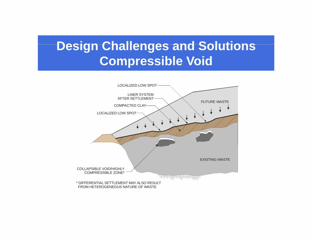
Design Challenges and SolutionsDesign Challenges and SolutionsCompressible Void
FUTURE WASTE
LINER SYSTEMAFTER SETTLEMENT
COMPACTED CLAY
LOCALIZED LOW SPOT
COMPACTED CLAY
LOCALIZED LOW SPOT
EXISTING WASTE
COLLAPSIBLE VOID/HIGHLYCOMPRESSIBLE ZONE*
* DIFFERENTIAL SETTLEMENT MAY ALSO RESULT FROM HETEROGENEOUS NATURE OF WASTE

Design Challenges and SolutionsDesign Challenges and SolutionsGeosynthetic Reinforcement
LINER SYSTEM
GEOGRIDREINFORCEMENT
LAYERS
VOID
SOFT AND/OR COMPRESSIBLE/COLLAPSABLE
ZONE
ZONE OFINFLUENCE
EXISTING WASTE
ZONE

D i Ch ll d S l tiDesign Challenges and SolutionsBuffer Soil
LINER SYSTEM
ENGINEERED FILLFOUNDATION LAYERFOUNDATION LAYER
LIMITS OF DIFFERENTIALSETTLEMENT EFFECTS
WASTEVOID

Design Challenges and SolutionsDesign Challenges and SolutionsDeep Dynamic Compaction
EXISTING WASTESURFACE WASTE SYSTEM AFTER
DEEP DYNAMICCOMPACTION
SURFACE AFTER
EXISTING WASTE