different options of adding optics to anitoa uls24 … options of adding optics to anitoa uls24 cmos...
TRANSCRIPT

ULS24 Application Note
www.anitoa.com
Different options of Adding Optics to Anitoa ULS24 CMOS Bio-optical Sensor Module
In the ULS24 Solution Kit, the ULS24 sensor is provided as a small module, that measures 20mm X 22mm. There are 3 methods to add optics to Anitoa ULS24 sensor module.
1. Use of-the-shelf lens such as C-mount or CS-mount lens or M-12 lens. 2. Use custom-designed lens, available from Anitoa and its partners. 3. Directly couple the ULS24 to the test object, such as a microfluidic chip running the assay.

ULS24 Application Note
www.anitoa.com
1 Use of-the-shelf C-mount, CS-mount or M-12 lenses
Since C mount lenses are usually high quality, with large diameter and aperture, this allows best light collection efficiency (hence low light sensing capability) and image quality. It is also possible to add filters using off-the-shelve filter mounting cubes and rings.
Anitoa provides a C-mount and CS-mount lens adapter shown in Figure 1a.
Figure 1. a, ULS24 in a C-Mount lens adapter. b: A Tamron C-mount lens mounted with ULS24.
C-mount lens and assemblies are however relatively bulky and expensive. So this type of optics is best suited for lab use or low volume prototypes. It is not optimal to use C-mount lens and assemblies in a compact and low-cost instrument.

ULS24 Application Note
www.anitoa.com
Below are some lenses we have tested:
Example 1: Tamron M118FM08
1.1.1 Field of view test results with Tamron M118FM08
With a front focal distance of 60mm, the field of view 35mm X 35mm.

ULS24 Application Note
www.anitoa.com
Example 2: Ricoh 12mm f/1.4 ½” FL Series
1.1.2 Field of view test result with Ricoh 12mm lens
With front focal distance of 90mm, the field of view is 35mm x 35mm

ULS24 Application Note
www.anitoa.com
1.1.3 Example 3: using Zoom C mount lens to image small features
We use a CANON C mount zoom lens, available at http://www.ebay.com/itm/MACRO-CANON-ZOOM-1-0-8-48MM-C-MOUNT-LENS-for-DIGITAL-MOVIE-CAMERA-CCTV-/271888925160, to image a microfluidic chip with small features
Image of digital PCR microfluidc chip using
Anitoa ULS24
PCR microfluidic
chip
Figure 3. Example of using C mount zoom lens with ULS24 to image digital PCR microfluidic chip

ULS24 Application Note
www.anitoa.com
1.1.4 How to choose a C mount lens?
To set up the system, first get the information about the lens system such as magnification, field of view, and working distance. Then calculate the focal length using Gaussian optics formula. See Figure 4
Figure 4 Lens parameter calculation
At last choose a suitable lens. Install the lens on the C mount holder. Make sure the object and lens is
on the principal optic axis in this process. Open the software. Set the frame on 24×24. Click the
“AutoRepeatCapture”. Adjust the focus. If you choose a fixed focus lens, you can change the working distance to make the image clearer. If you choose a zoom lens, you can change the focal length.

ULS24 Application Note
www.anitoa.com
1.2 Use M-12 lens
M-12 lens are cheap and small, they can be used for quick evaluation purposes. Although with this method, the image quality and light collection efficiency is non-optimal.
Below is an example of using M12 lenses with ULS24. We ordered several parts from www.m12lenses.com. They are:
1. PT-LH009P Plastic M12 Lens Holder, 20mm Hole Spacing;
2. PT-03618MP 3.6mm, F1.8 Lens;
3. Or PT-02820MP 3.6mm, F2.0 Lens
1.2.1 Attaching Lens Holder to the ULS24 Sensor Board
We found that it is difficult to use the included metal screw to attach the holder to the board, although the hole pattern actually match. Therefore we recommend using a small amount of glue (Epoxy or Super glue) to attach the holder.

ULS24 Application Note
www.anitoa.com
1.2.2 Attach lens and adjust focus
The lens is screwed into the holder. The lens has a fixed focal length. To adjust focus, we just screw the lens in and out of the holder to adjust the distance between the lens plane and sensor plane. Below is an empirical setting to achieve good focus:
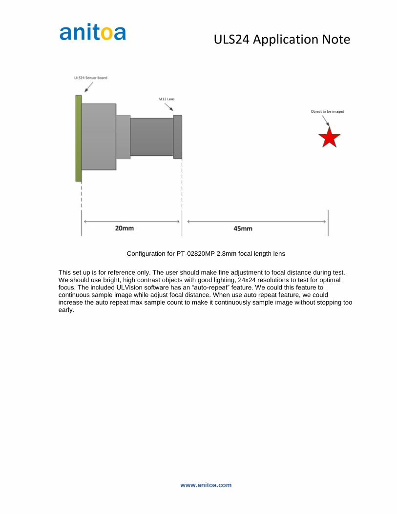
25mm 30 – 40mm
ULS24 Sensor board
M12 Lens
Object to be imaged
Configuration for PT-03618MP 3.6mm focal length lens
ULS24 Application Note
www.anitoa.com
Configuration for PT-02820MP 2.8mm focal length lens
This set up is for reference only. The user should make fine adjustment to focal distance during test. We should use bright, high contrast objects with good lighting, 24x24 resolutions to test for optimal focus. The included ULVision software has an “auto-repeat” feature. We could this feature to continuous sample image while adjust focal distance. When use auto repeat feature, we could increase the auto repeat max sample count to make it continuously sample image without stopping too early.

ULS24 Application Note
www.anitoa.com
Auto repeat feature
Auto repeat parameters

ULS24 Application Note
www.anitoa.com
2 Use Custom lenses provided by Anitoa and its partners
2.1 Anitoa WLF Lens design
Below is a lens design provided by Anitoa, that is both compact and high efficiency. This is optimized for fluorescence and chemiluminescence sensing in a compact instrument. The efficiency of Anitoa WLF lens design approaches that of a C-mount lens, with much smaller footprint and lower cost in high volume.
Angle of view ≦15°(±7.5°)
Focal length 13. 67mm
Aperture 10mm
F/number 1.4
CMOS sensing area
3.6mm*3.6mm
Pixel size 150μm*150μm
Front focal distance
∞--50mm
Back focal distance
13.67mm—18.81mm
Front VS Back focal distance
0 100 200 300 400 500 600 700 800 900 1000
13
14
15
16
17
18
19
物距 /mm
像距
/mm
ULS24 Application Note
www.anitoa.com
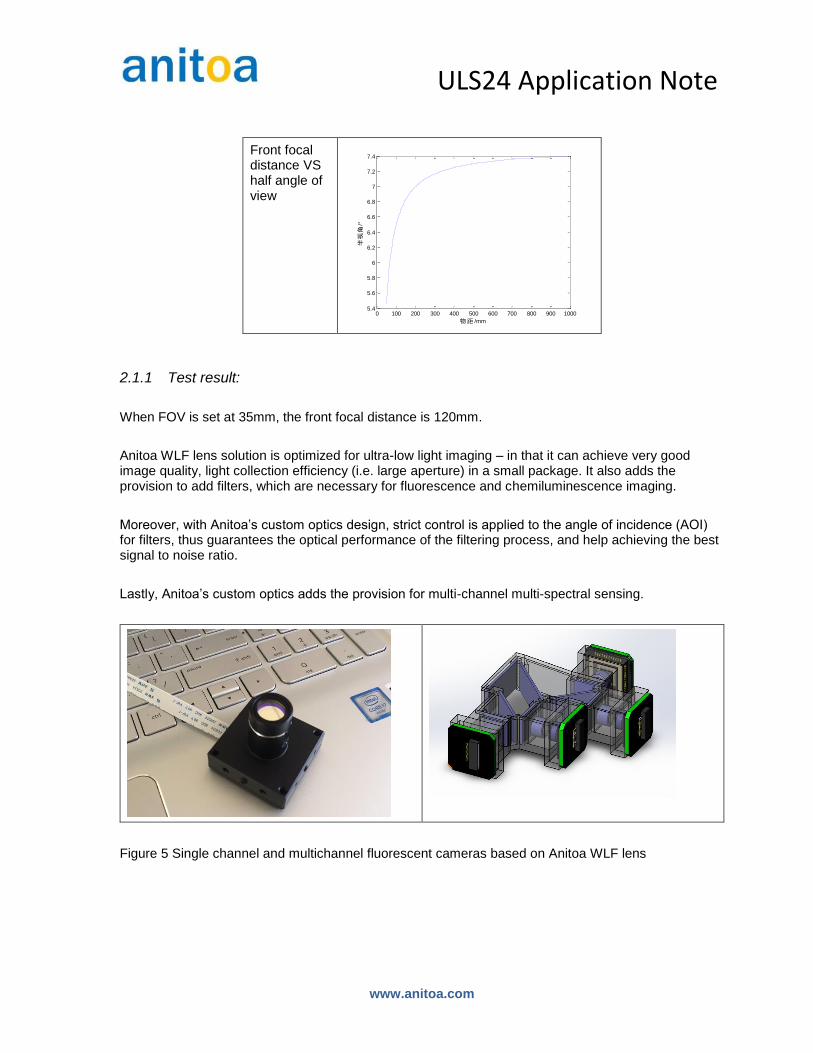
Front focal distance VS half angle of view
2.1.1 Test result:
When FOV is set at 35mm, the front focal distance is 120mm.
Anitoa WLF lens solution is optimized for ultra-low light imaging – in that it can achieve very good image quality, light collection efficiency (i.e. large aperture) in a small package. It also adds the provision to add filters, which are necessary for fluorescence and chemiluminescence imaging.
Moreover, with Anitoa’s custom optics design, strict control is applied to the angle of incidence (AOI) for filters, thus guarantees the optical performance of the filtering process, and help achieving the best signal to noise ratio.
Lastly, Anitoa’s custom optics adds the provision for multi-channel multi-spectral sensing.
Figure 5 Single channel and multichannel fluorescent cameras based on Anitoa WLF lens
0 100 200 300 400 500 600 700 800 900 10005.4
5.6
5.8
6
6.2
6.4
6.6
6.8
7
7.2
7.4
物距 /mm
半视角
/°
ULS24 Application Note
www.anitoa.com
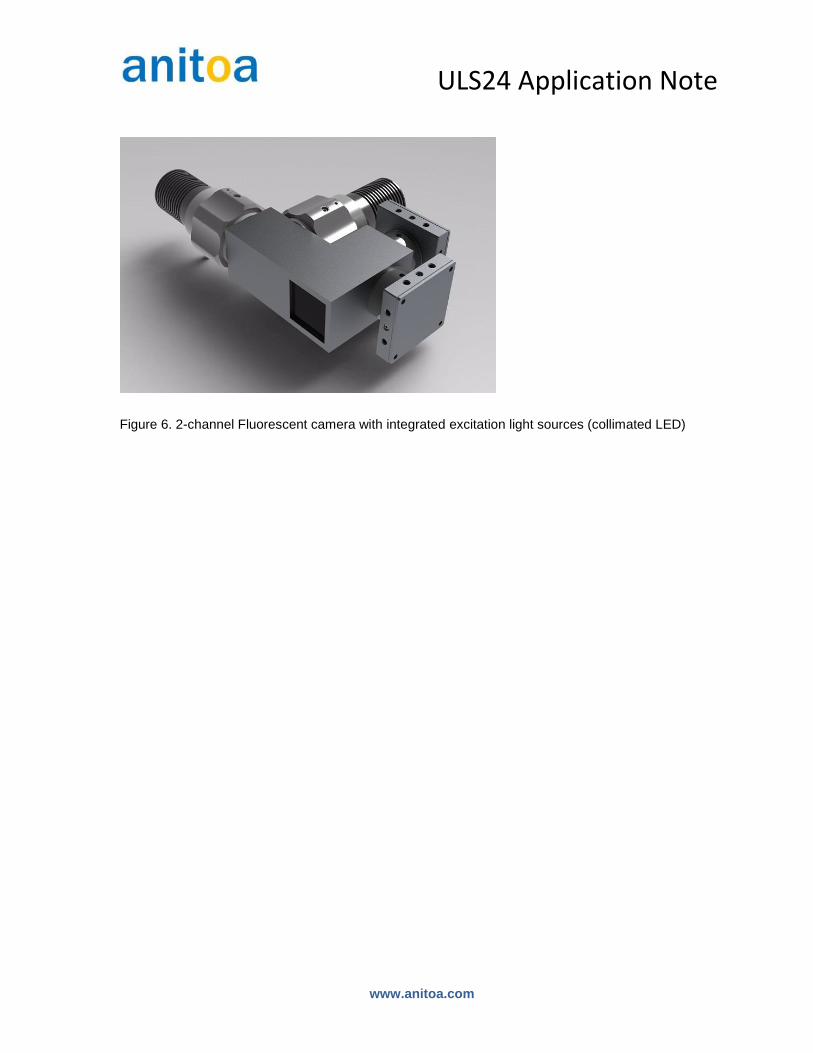
Figure 6. 2-channel Fluorescent camera with integrated excitation light sources (collimated LED)

ULS24 Application Note
www.anitoa.com
2.2 Anitoa QYZ Lens Design
The Anitoa QYZ lens design is optimal for small field of view size and good light collection efficiency in a small package. This solution is optimal for imaging microfluidic chips and lateral flow test strips.
The optimal field of view size for QYZ lens is 3mm X 3mm to 10mm X 10mm.
Resolution: (of the optics) 45um RMS
Aperture: 15mm
Front focal distance: 35mm to ∞
Effective focal length: 30.97mm
Wavelength range 400nm to 800nm
Figure 7. Anitoa QYZ lens in a small camera design optimized for microfluidics and lateral flow chemistry in a compact platform.
ULS24 Application Note
www.anitoa.com
3 Directly couple Anitoa CMOS Bio-optical sensor to Assay
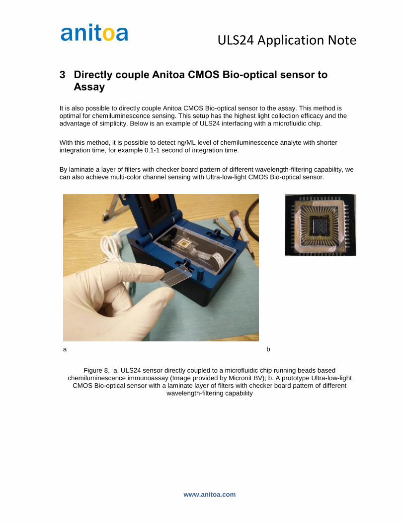
It is also possible to directly couple Anitoa CMOS Bio-optical sensor to the assay. This method is optimal for chemiluminescence sensing. This setup has the highest light collection efficacy and the advantage of simplicity. Below is an example of ULS24 interfacing with a microfluidic chip.
With this method, it is possible to detect ng/ML level of chemiluminescence analyte with shorter integration time, for example 0.1-1 second of integration time.
By laminate a layer of filters with checker board pattern of different wavelength-filtering capability, we can also achieve multi-color channel sensing with Ultra-low-light CMOS Bio-optical sensor.
a b
Figure 8, a. ULS24 sensor directly coupled to a microfluidic chip running beads based chemiluminescence immunoassay (Image provided by Micronit BV); b. A prototype Ultra-low-light
CMOS Bio-optical sensor with a laminate layer of filters with checker board pattern of different wavelength-filtering capability