diesel locomotive operating manual - finiusers.fini.net/~bersano/english-anglais/emd-f7.pdf ·...
TRANSCRIPT


DIESEL LOCOMOTIVE OPERATING MANUAL
NO. 1310 FOR
MODEL F7 With Vapor Car Steam Generator
and Elesco Steam Generator
4th Edition
March, 1950
This manual has been written to specifically cover operation of the F7 locomotive. However, it may be used for the operation of other freight type General Motors locomotives.
Coverage of the Dynamic Brake is included. The manual is written to be complete with or without this coverage so that on locomotives not equipped with Dynamic Brake reference to this subject may be elimi-nated without detracting from coverage of the locomotive.
Price $2.50
ELECTRO-MOTIVE DIVISION
PRINTED IN U.S. A.
General Motors Corporation LA GRANGE, ILLINOIS, U. S. A.

ELECTRO-MOTIVE OPERATING MANUAL
ELECTRO-MOTIVE DIVISION F7 DIESEL LOCOMOTIVES
GENERAL DATA
Weight (fully loaded) "A" Unit (approx.) ................ 230.000 lbs. "B" Unit (approx.) ............ 230,000 lbs.
Fuel Oil Capacity (per unit) .......................................... l.200 gal. Lube Oil Capacity (per engine) .................................... 200 gal. Cooling Water Capacity "A" Unit-"G" Valve Level 230 gal.
"B" Unit-"G" Valve Level 215 gal. Steam Generator Water Tank Capacities (if used):
Vertical Tank-"A" Unit........................................ 500 gal. "B" Unit ........................................ I.200 gal.
Hatch Tank-"A" Unit.......................................... 600 gal. "B" Unit.......................................... 600 gal.
Tank Under 1600:jt Steam Generator ................ 200 gal. Gear Ratios and Maximum Permissible Speeds:
65/12 ........ 55 MPH 62/15 ........ 65 MPH 6l1 16 ........ 71 MPH 59. 18.... .... 83 MPH 58/19 ........ 89 MPH 57 /20 ........ 95 MPH 56/21.. ...... 102 MPH
Sand Capacity (per unit) .......................................... l6 cubic feet Number of Drivers (per unit) ................................................ 4 pair Wheel Diameter .......................................................................... 40" Weight on Drivers .................................................................. 100% Truck Centers ........................................................................ 30' 0" Truck Rigid Wheelbase .......................................................... 9' 0' Minimum Curve Radius .......................................................... 274' Center of Gravity above Rail (approx.l ................................ 63" Length: Between Coupler Pulling Faces-" A" Unit.. ...... 50' 8"
"B" Unit ........ 50' O" Height: Over Horns ........................................................ 14' ll 1/4" Width: Outside Grabirons ................................................... 10' 8"

ELECTRO-MOTIVE DIVISION e GENERAL MOTORS CORPORATION
F7·0-1049
TABLE OF CONTENTS
SECTION 1 - GENERAL DESCRIPTION
Engineman's Controls Engineman's Instrument Panel Switches Air Brake Equipment Miscellaneous Equipment Engine Room
SECTION 2 - NORMAL OPERATION
Preliminary Handling a Train Braking Miscellaneous Operating Instructions
SECTION 3 - SPECIAL CONDITIONS AND
GENERAL
Page
100
102 106 108 109 110 115
200
200 205 209 211
PROBLEMS DURING OPERATION 300
Problems During Operation 309 Specific Difficulties 313
SECTION 4 - COOLING, LUBRICATING OIL AND FUEL OIL SYSTEMS 400
Cooling System 400 Lubricating Oil System 401 Fuel Oil System 402
SECTION 5 - ON-THE-ROAD TROUBLE-SHOOTING 500
SECTION 6 - STEAM GENERATOR 600

NOTES

ELECTRO-MOT1VE DIVISION e GENERAL MOTORS CORPORATION
F7-1-1049 DESCRIPTION
SECTION I
GENERAL DESCRIPTION
A description and general location of equipment on the basic F7 locomotive is given in this section.
A locomotive consists of one or more units rated at 1500 horsepower each. The units which are equipped with an operating cab are designated "A" units, those without cabs as "B" or Booster units. Different com-binations of units are used, depending on the horsepower and operating requirements.
100 Diesel Engines Each unit has a 16-cylinder 2-cycle Model 567B Diesel engine which drives
the main generator and auxiliaries described later.
101 Main Generator and Alternator The main generator and alternator assembly are directly
connected to the Diesel engine crankshaft through a flexible coupling. Two electrically separate sections are mounted on the same shaft and designated as Model D12-D14. The D12 portion produces direct cur-rent at a nominal voltage of 600 volts for operation of the traction motors. The D14 section, built into the engine end of the main generator frame is a three phase, 80 KW alternating current generator which furnishes power to drive the engine water cooling fans and the traction motor blowers.
102 Traction Motors Four traction motors are used in each unit, mounted one on each axle.
Each motor is geared to the axle which it drives by a motor pinion gear meshing with an axle gear. The gear ratio between the two gears is expressed as a double number such as 62/15. In this case, the axle gear has 62 teeth while the pinion has 15 teeth.
- 100 -

ELECTRO-MOTIVE DIVISION 8 GENERAL MOTORS CORPORATION
DESCRIPTION F7-1-1049
During acceleration four steps of traction motor electrical connections (called transition) are used:
1. Series-Parallel 3. Parallel 2. Series-Parallel-Shunt 4. Parallel-Shunt
This transition compares roughly to ''hooking up" a steam locomotive making it possible to utilize the full horsepower output of the engines and takes place automatically while operating locomotives in automatic transition position. When operating in manual transition position, the engineman must move the transition lever to the proper position when the transition indicator reaches a shifting point_ During deceleration the steps take place in reverse order.
103 Reversing Locomotive Reversing the locomo-tive is accomplished by moving the reverse lever
in the control stand to the desired direction. The re-verse lever must be moved only when the locomotive is standing still.
104 Auxiliary Equipment Auxiliary equipment in the F7 locomotive is driven entirely by direct
drive from the Diesel engine or by separate electric motors. No belts are used in the locomotive.
The 10 KW auxiliary generator is directly driven from the Diesel engine. It produces direct current at approximately 74 volts to charge the storage batteries and supply the low voltage circuits for lighting, control, generator field excitation, fuel pump operation, etc. The air compressor is driven through a flexible coupling from the armature shaft of the main generator. It is a three cylinder, two stage compressor.
An electric driven blower is provided for each traction motor. These blowers supply the cooling air for the traction motors. Electric driven cooling fans supply the air for the engine cooling water radiators.
- 101 -

ELECTRO-MOTIVE DIVISION e GENERAL MOTORS CORPORATION
F7-1-1049 DESCRIPTION
ENGINEMAN'S CONTROLS Three levers and the two brake valve handles
control the entire operation of the locomotive. These are the throttle, reverse and transition levers which are mounted in the control stand and the independent and automatic brake valve handles.
105 ThroHie Lever This lever controls the speed of the engines and the train speed in normal
operation. The position of the throttle is shown in the illuminated indicator above the lever. The throttle has ten positions, stop, idle and running speeds 1 to 8. Stop can be obtained by depressing the emergency stop button on the end of the throttle lever and pushing the throttle lever 1 step beyond the idle position. This stops all engines. Idle position is as far forward as the throttle lever can be moved without depressing the emergency stop button. Each running notch on the throttle increases the engine speed 75 RPM from 275 RPM at idle to 800 RPM at full throttle. Mechanical interlocks prevent the throttle from being opened more than one notch at a time to prevent rough train han-dling. The throttle may be closed completely with one motion in an emergency, but should be closed only one notch at a time in normal operation.
106 Reverse Lever The reverse lever can be re-moved from the control stand in neutral position
only. This locks the operating controls in the control stand. With the reverse lever in neutral position, the power circuits will not close.
107 Transition Lever This lever is on the left side of the control stand. Its position is shown
in an illuminated indicator in the control stand. The locomotive is started with the transition lever in the No. 1 position and is advanced as the speed increases
- 102 -

ELECTRO-MOTIVE DIVISION e GENERAL MOTORS CORPORATION
DESCRIPTION F7-1-249
LEGEND OF ENGINEMAN'S CONTROLS
1. Automatic Brake Valve 2. Full Release Selector Cock 3. First Service Position Cock 4. Instrument Panel Light Switch 5. Safety Control Cock 6. Brake Valve Cutout Cock 7. Safety Control Foot Pedal 8. Rotair Valve 9. Cab Heater Steam Valve
10. Reverse Lever 11. Transition Lever 12. Speed Recorder 13. Horn Cords 14. Load and Transition Indicating Meter 15. Throttle Lever 16. Heater Switch 17. Windshield Wiper Valve 18. Equalizing Reservoir and Main Reservoir Air Gauge 19. Independent Brake Valve 20. Brake Pipe and Brake Cylinder Air Gauge 21. Bell Valve 22. Application Pipe and Suppression Pipe Air Gauge
(If Used) 23. Engineman's Watch Receptacle (If Used) 24. Wheel Slip Indicator Light 25. Dynamic Brake Warning Light 26. PCS Open Light
- 103 -

ELECTRO-MOTIVE DIVISION e GENERAL MOTORS CORPORATION
F7-1-249
Engineman's Controls Fig. 1-1
- 104 -
DESCRIPTION

ELECTRO-MOTIVE DIVISION e GENERAL MOTORS CORPORATION
DESCRIPTION F7-1-249
The dial of the meter is graduated into amperes starting at 0 at the left and going to 1000 amperes at extreme right of the scale. There are four transition zones (safe operating zones) colored green, and an overload zone colored yellow.
A red diamond and a black line at 825 amperes show the maximum continuous current rating. A red triangle at 600 amperes shows the maximum permissi-ble current when using dynamic brakes. A white pointer moves across the dial to indicate the amount of trac-tion motor amperes.
A blank space exists between the transition areas. When shifting manually from one area to a higher area, wait until the pointer has reached the edge of the higher area and shift promptly. When shifting to a lower area, wait until the pointer has reached the edge of the lower area and shift promptly.
A plate is mounted below the meter dial showing the time it is permissible to operate at different stages of overload. These "short time overload" ratings are accumulative.
112 Wheel Slip Light This light indicates that the locomotive wheels are slipping, and the throttle
should be reduced one or more notches to stop the slipping. The wheel slip light does not flash when transition is made from series-parallel to parallel and back to series-parallel as it did with older locomotives. If the light should flash, consistently, during transition, this condition should be reported.
113 Dynamic Brake Warning Light (If Used) If the dynamic brake in any of the units is over-
loaded this light will indicate that the brake should be reduced.
- 107 -
ELECTRO-MOTIVE DIVISION e GENERAL MOTORS CORPORATION
F7-1-1049 DESCRIPTION
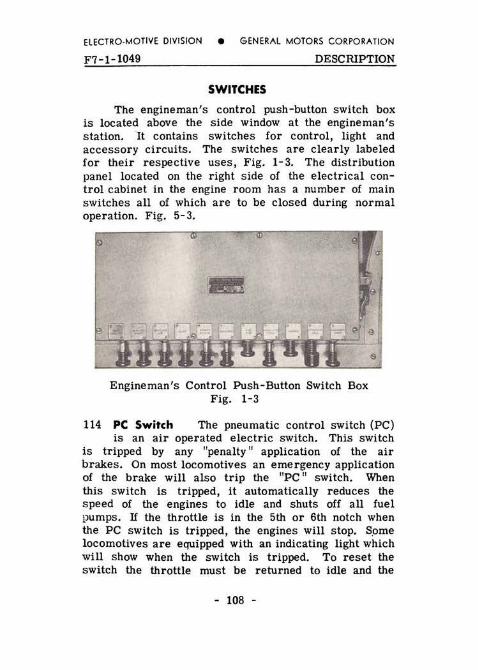
SWITCHES The engineman's control push-button switch box
is located above the side window at the engineman's station. It contains switches for control, light and accessory circuits. The switches are clearly labeled for their respective uses, Fig. 1-3. The distribution panel located on the right side of the electrical con-trol cabinet in the engine r oom has a number of main switches all of which are to be closed during normal operation. Fig. 5-3 .
Engineman's Control Push-Button Switch Box Fig. 1-3
114 PC Switch The pneumatic control switch (PC) is an air operated electric switch. This switch
is tripped by any "penalty" application of the air brakes. On most locomotives an emergency application of the brake will also trip the "PC" switch. When this switch is tripped, it automatically reduces the speed of the engines to idle and shuts off all fuel pumps. If the throttle is in the 5th or 6th notch when the PC switch is tripped, the engines will stop. Some locomotives are equipped with an indicating light which will show when the switch is tripped. To reset the switch the throttle must be returned to idle and the
- 108 -
ELECTRO-MOTIVE DIVISION e GENERAL MOTORS CORPORATION
DESCRIPTION F7-1-249
brake "recovered," When this has been accomplished the "PC" switch will reset itseli and the indicating light will go out.
AIR BRAKE EQUIPMENT
The 24 RL brake equipment is normally used on the F7 locomotives, The air brake gauges are located on the instrument panel in front of the engineman. In general, the cab air brake equipment consists of the automatic brake valve, the independent brake valve and the K-2-A Rotair valve, a manually operated valve having four positions and located to the right of the controller as shown in Fig. 1-1. The automatic brake valve handle has 6 positions - release, running, first service, lap, service and emergency; and may be of the rigid or hinged handle type. The automatic brake valve handle (rigid or hinged handle) is removable in the running position. The handle should be removed when a double cab locomotive is being operated from the opposite end. The hinged handle, if required by the railroad, is used to suppress a safety control from the foot pedal by depressing the handle to a horizontal position. On some railroads a sanding bail provides sanding by further depressing the handle.
The brake valve, Fig, 1- 4, also contains:
1. Brake valve cutout cock, located on the filling piece portion.
2. Safety control cutout cock, located on the service application portion.
3. First service position cock. 4. Full release selector cock.
116 Independent Brake Valve The S-40-F inde-pendent brake valve handle has two positions, re-
lease and full application, with the application zone between the two positions. The brake valve is of the
- 109 -
ELECTRO-MOTIVE DIVISION e GENERAL MOTORS CORPORATION
F7-1-249 DESCRIPTION
self-lapping type which automatically laps off the flow of air and maintains brake cylinder pressure, when the application pressure reaches the value correspond-ing to the position of the brake valve handle in the application zone. Release of locomotive brakes after automatic application is obtained by depressing the independent brake valve handle in release position.
117 K-2-A Rotair Valve The four positions of the K-2-A Rotair valve are "FRGHT," "FRGHT LAP"
"PASS LAP" and ''PASS. " See "Operation" for handling of this valve.
118 Safety Control Foot Pedal The safety control foot pedal is located in front of the engineman's
seat. On locomotives equipped with the DS-24-H brake valve, having the hinged automatic brake valve handle, the handle provides an alternate control when it is de-pressed sufficiently to just contact the sanding bail. Either the pedal or the automatic brake valve handle must be kept depressed at all times except when the locomotive is stopped and the locomotive brakes are applied (30 pounds or more brake cylinder pressure). If both the foot pedal and the automatic brake valve are released at the same time, a penalty application of the brakes will result.
MISCELLANEOUS EQUIPMENT
119 Sanding Valve When the locomotive is equipped with the hinged automatic brake valve handle,
sanding is accomplished by depressing the lever beyond the safety control position previously described. This movement operates the sanding bail which opens a port to supply air to the sanding eouipment. On locomotives having a rigid handle on the automatic brake valve, an independent sanding valve is installed. This lever is operated by pushing the lever forward until it latches.
- 110 -

ELECTRO-MOTIVE DIVISION
DESCRIPTION
BRAKE VALVE GUT-OUT COCK (DOUBLE HEADING COCK) OPEN POSITION-HANDLE HORIZ. CLOSED POSITION-HANDLE VERTICAL
SHIFTER LEVER AUTO. POSITION "AU" EXPOSED. STRAIGHT AIR POS "SA" EXPOSED__
FUl.l RELEASE . -
LEASE
• GENERAL MOTORS CORPORATION
F7-1-249 DSE-24-H BRAKE VALVE
FIRST SERVICE POSITION COCK CUTS OUT FIRST
SERVICE AND BRAKE PIPE MAINTAINING FUNCTIONS
FIRST SERVICE POSITION COCK CUTS IN FIRST SEA· VICE AND BRAKE PIPE MAINTAINING FUNCTIONS
HANDLE OVER "F.V" MAIN RES RELEASE HANDLE OVER "M R"
Q-24 CONTROL VALVE
RETARDED RECHARGE COCK HANDLE OVER LETTERS 1FRT" RESTRICTS AUX RESERVOIR CHARGING
Fig. 1-4
GRADUATED RELEASE CAP
RET ARCEO RECHARGE COCK HANDLE OVER LETTERS "PASS"-FAST AUXILLIARY RESERVOIR CHARGING
- 111 -

ELECTRO-MOTIVE DIVISION
F7-1-1049 • GENERAL MOTORS CORPORATION
DESCRIPTION
K-2-A ROTAIR VALVE--:
HANQLE OVER LETTERS "FRGT" CUTS IN CONTROLLED EMERGENCY FEATURE, SPLIT SERVICE REDUCTION, 6 INDEPENDENT BRAKE VALVE
HANDLE OVER LETTERS ''FRGT LAP" :~-· CUTS OUT INDEPENDENT BRAKE VALVE CONTROLL· ED EMERGENCY STILL IN EFFECT
HANQLE OyER LETTERS "PASS LAp" ~ CUTS OUT CONTROLLED EMERGENCY 8 THE IN· DEPENDENT BRAKE VALVE
HANQLE OVfR LETTERS "PASS" ALL FEATURES REMAIN CUTOUT AS IN "PASS LAP," EXCEPT INOE PENDENT BRAKE VALVE IS CUT IN
:110 POSITION USED FOR TRAILING "A" UNITS,
INDEPENDENT BRAKE VALVE---
dNIT CONTROL VALVE SECTION
NOTE WHEN DOUBLE HEADING, HtE ROTAIR VALVE ON THE SECOND OPERATING UNIT SHOULD BE LEF'T IN A LIVE POSITION, "FRGT" OR ''PASS", TO RE-TAIN USE OF INDEPENDENT BRAKE VALVE
WHEN OPERATING A ~8" UNIT ALONE WITH THE HOSTLER'S CONTROL, THE CONTRDt.l.EO EMER-GENCY SELECTOR COCK MUST BE PLACED IN "PASS. POSITION TO EFFECT QUICK ACTING EMERGENCY 1r: NEEDED
I
HANDLE OVER "F" CUTS IN CONTROLLED-EMERGENCY BRAKE CYLIN· OER PRESSURE DEVELOPMENT FEATURE
I-IANDLE OVER "t." POSITION NOT USED WITH OUR EOUIF'MENT HAN~ OLE MUST BE IN PASSENGER OR FREIGHT POSITION
'HANDLE OVER ·p~ GUTS OUT CONTROLLED-EMERGENCY' BRAKE CYL-INDER PRESSURE DEVELOPMENT FEATURE
VIEW OF PIPE BRACKET FOR CONTROL VALVES SHOWING CONTROLLED-EMERGENCY CUT·OUT COCK IN "e" UNITS
Cock Handle Positions 24 RL Brake
All Types Of Service Fig. 1-4
- 112 -

ELECTRO-MOTIVE DIVISION e GENERAL MOTORS CORPORATION
DESCRIPTION F7-1-649
119 Speed Recorder-Locomotive Overspeed Control The speed recorder, located in front of the control
stand, is a hydraulically operated speed indicator with a speed recording tape and an odometer. It is driven from the number 1 axle of the ''A" unit, through a flexible cable. It contains a maximum speed device which will initiate a full service application of the brakes and trip the PC switch when the maximum speed setting is exceeded. On some railroads, instead of a full service application of the brakes, the brakes go into emergency.
120 Unit Selector Switch (Dynamic Brake) The unit selector switch located next to the engine-
man's instrument panel has four positions and should be set corresponding to the number of units makingup the locomotive. The unit selector switch should be set before leaving the maintenance point. If one or more engines should be isolated en route this switch must not be changed. The only time this switch is changed is if the locomotive consist is changed.
121 Windshield Wipers The windshield wipers are controlled by valves, one of which is located on
the engineman's instrument panel, and one on the panel on the fireman's side of the cab. These wipers operate independently of each other. The wipers s •. ould not be run on a dry window as dirt on the glass or blade will scratch the glass.
122 Horn Valves The horns are operated by air valves which are controlled by pull-cords, above
the control stand. The horn shut-off valve is located in front of the No. 2 main reservoir.
123 Locomotive Bell The locomotive signal bell is under the locomotive floor behind the pilot on
the left side. It is operated by an air valve located
- 113 -

ELECTRO-MOTIVE DIVISION e GENERAL MOTORS CORPORATION
F7-1-649 DESCRIPTION
at the engineman's station. The bell shut-off valve is located to the left side of the front end of No. 2 main reservoir.
124 Cab Heaters A cab heater is located on each side of the cab. Hot water from the engine cool-
ing water system passes through the heaters and motor driven fans provide air circulation. The flow of water to both heaters is controlled by a valve in the supply line, located over the left hand engine room steps. This valve must be kept wide open at all times in freezing weather. The output of each heater can be varied by use of the cab heater switches. The switches have four positions "OFF" 1, 2, 3, which provide three dif-ferent motor speeds. If engine in the lead unit is shut down in freezing weather. steam may be admitted to the cab heaters.
125 Defrosters Each side of the cab is equipped with a defroster motor and fan which blows heated
air on the inside of the front cab windows. Both motors are turned on and off by the one defroster switch in the control push-button switch box.
12G Classification Lights A permanently fixed, clear bull's-eye is provided on each side of the
nose. Inside the nose and behind each bull's-eye, a small compartment contains the classification light b1:1lb and colored lenses. Red and green lenses are provided in each compartment which can be moved into a posi-tion between the bulb and the bull's-eye. To accom-plish this, a locking pin is removed, the desired lens swung into place and the locking pin replaced. The lenses are accessible from the inside of the nose sec-tion through hinged doors in the compartments. When both red and green lenses are out of position the per-manent bull's-eye lens will show a white light, thus making three colors available.
- 114 -

ELECTRO-MOTIVE DIVISION e GENERAL MOTORS CORPORATION
DESCRIPTION
ENGINE ROOM
The two ends of the engine are designated "FRONT" and "REAR" as shown in Fig. 1-5, r;hich will serve to identify the cylinder locations, ends and sides of the engine, as they are referred to in this manual. The governor, water pumps, and lu-bricating oil pumps are on the "FRONT END. " The blowers, oil separator and generator are mounted on the "REAR END."
The engine is placed so that its rear end is toward the front end of the unit when the unit is operating in its normally forward direction.
-EFT SlDE
F7-1-64Q
FRONT END
: 3
4
:3.
' 7
REAR END
Fig. 1-5
127 Engine and Panel This panel is mounted on a frame which supports the
engine cooling water tank near the governor end of the engine. Each power plant has its own engine control and instrument panel on which are mounted the lube oil pressure and suction gauges, fuel tank gauge, along with the start, stop, fuel pump and isolation switches.
128 Isolation Switch This switch has two positions "START" (handle horizontal} and "RUN" (handle
pointing down vertically). In ,. START" position, the power plant is disconnected from the control circuit, and engine is reduced to idle speed. The engine will remain at idle speed and will not respond to throttle controL The power contactors in the electrical control
- 115 -

ELECTRO-MOTIVE DIVISION e GENERAL MOTORS CORPORATION
F7-1-649 DESCRIPTION
cabinet will not operate when the transition lever is moved. In dynamic braking, the unit will exert no retarding effect. The "Alternator Failure'' alarm is inoperative. The "START'' and "STOP'' buttons are effec-tive only when the isolation switch is in .. START" position.
129 Governor, Governor Speed and Safety Control The engine 1s equipped with a Woodward Governor
which includes an electro-hydraulic governor speed control, and an unloader used during transition. In case of low oil pressure or high vacuum on the suction side of the lube oil pump, the engine governor will stop the engine. The alarm bells will sound in all units of the locomotive. The yellow "Low Oil" and the blue "Alternator Failure" signal light will show in the unit affected. When the governor safety control stops the engine, the push button on the front of the governor housing moves out approximately 3/8" exposing a red band around the shaft of the button. The governor reset push button must be pressed in to extinguish the "Low Oil'' alarm lights and the isolation switch moved to .. START'' position to extinguish the .. Alternator Failure'' alarm lights. Both actions are necessary to stop alarm bells. The push button will not trip if the engine stops due to placing of throttle in emergency stop position, operation of manual lay shaft control lever, tripping of ground protective relay when throttle is in run 5 or run 6, or use of the "STOP" button for normal shutdown. In these instances, the ., LOW OIL" alarm lights will not light but the "Alternator Failure" alarm will function (except when the "STOP" button is used) to serve as a warning that an engine is stopped. When the engine is stopped by governor control action, the push button must be reset before the engine can be started. When the engine is started and run at idliflg speed, the governor will stop the engine again after approximately forty seconds, if the condition still exists which caused the original shutdown. This time delay is provided to allow
- 116 -
ELECTRO-MOTIVE DIVISION e GENERAL MOTORS CORPORATION
DESCRIPTION F7-l-649
a check to determine the cause of the shutdown. How-ever, if an attempt is made to run the engine above idling speed during the delay period, the governor will stop the engine at once should the oil pressure be low or the oil pump suction be high.
130 Electrical Cantrol Cabinet The electrical control cabinet contains the various contactors,
relays, and other equipment necessary for the elec-trical and electro-pneumatic control of the unit.
131 Control Air Pressure Regulator The "control air," for operating power contactors, reverser
and cam switch is supplied from the main reservoir and reduced to 80 ::!: 3 pounds by the control air pres-sure regulator. The pressure regulator is located behind the steps leading into the operating cab on the right (engineman' s) side of locomotive. The pressure is indicated on a gauge in the distribution panel just below main battery switch.
132 Load Regulator The load regulator is located diagonally below the engine control panel, its
movement is controlled by a pilot valve and a dump valve in the engine governor. The load regulator con-trols the loading of the main generator, and auto-matically maintains a constant horsepower output, corresponding to each throttle position throughout the entire range of engine speed.
133 Layshaft Manual Control Lever The layshaft manual control lever is attached to the end of the
injector layshaft, at the left front corner of the engine and is accessible when standing at the engine control panel. It may be used to shut engine down manually, or to bring the engine speed to idle, as when taking an engine "off the line." It is also used to increase engine speed gradually when putting an engine ''on the
- 117 -
ELECTRO-MOTIVE DIVISION e GENERAL MOTORS CORPORATION
F7-1-1049 DESCRIPTION
line," when locomotive is under power.
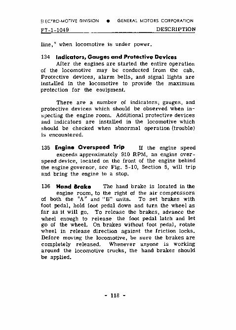
134 Indicators, Gauges and Protective Devices After the engines are started the entire operation
of the locomotive may be conducted from the cab. Protective devices, alarm bells, and signal lights are installed in the locomotive to provide the maximum protection for the equipment.
There are a number of indicators; gauges, and protective devices which should be observed when in-specting the engine room. Additional protective devices and indicators are installed in the locomotive which should be checked when abnormal operation (trouble) is encountered.
135 Engine Overspeed Trip If the engine speed exceeds approximately 910 RPM, an engine over-
speed device, located on the front of the engine behind the engine governor, see Fig. 5-10, Section 5, will trip and bring the engine to a stop.
136 Hand Brake The hand brake is located in the engine room, to the right of the air compressors
of both the "A" and "B" units. To set brakes with foot pedal, hold foot pedal down and turn the wheel as far as it will go. To release the brakes, advance the wheel enough to release the foot pedal latch and let go of the wheel. On brakes without foot pedal, rotate wheel in release direction against the friction locks. Before moving the locomotive, be sure the brakes are completely released. Whenever anyone is working around the locomotive trucks, the hand brakes should be applied.
- 118 -
NOTES

ELECTRO.MOTIVE DIVISION e GENERAL MOTORS CORPORATION
F7-2-249
SECTION 2
NORMAL OPERATION
OPERATION
Successful road operation and dependable function of all F7 locomotive components are entirely dependent upon the quality of inspection and repair at regular maintenance periods, as well as the proficiency of the operating crew. As a supplement to terminal mainte-nance a "pre-service check" by the engine crew upon boarding the locomotive, will generally preclude the necessity of anyone entering the engine room while under way.
It is strongly recommended that the items listed below be checked thoroughly and without omission, for carelessness is most often the cause of road failures which cause unnecessary delays.
PRELIMINARY 200 When Boarding the Locomotive
A. Inspect exterior of locomotive and running gear for:
1. Liquids leaking from the locomotive. 2. Loose or dragging parts. 3. Proper positioning of Angle Cocks and Shut-Off
Valves. 4. Observe brake cylinder piston travel, if air
brakes are set. B. In the engine room with engines running (if engines
are not running, see Art. 300 for starting instruc-tions), the following check is to be made in all units.
1. Check for oil, water and fuel leaks. 2. Check gauges, indicators and switches as listed
in Fig. 2-1. - 200 -

ELECTRO-MOTIVE DIVISION e GENERAL MOTORS CORPORATION
opERATION F7-2-249
L_j, ....... 5. 6. 7. 8.
Location Gauges Relays And Equipment Fig. 2-1
- 201 -

DIVISION e GENERAL MOTORS CORPORATION
F7-2-249 OPERATION
ENGINE ROOM CHECK CHART
Item Readinr Ret. t
Idle No.
1. Aux. Gen. Ammeter 318 B
2. Contactors St. 319
3. Control Air Pressure + - 3
4. Batterv Ammeter or + or +
5, Ground ReJav 6. Main Reservoir to
7. Air Intercooler B. Air Pres.
FAILURE CHECK. Should a unit fail to perform prop-erly check items lettered as "X." The letters R, B, YB, indicate items that will cause Red, Blue, or Yellow and Blue lights to come on. See Art. 311 for details.
9. Lube Level Fuel Ind as 8-11 823
11. Gov. Level Betveea
12 Water Pressure to to R
13. !Water Temoerature Mia. - R
14. Isolation Switch 324
15. Lube Pressure to 129
16. Fuel 17. Load other
18 Lube Suction Green 129
19. Water Level R
Gen. Water Supply Needed
21 Oversoeed Trip to 327 B
.22. Fuel Flow 826 I
Fig. 2-1
- 202 -
ELECTRO-MOTIVE DIVISION e GENERAL MOTORS CORPORATION
OPERATION F7-2-1049
3. Check position of transition cutout switches. They should be pinned or sealed in the posi-tion in which the locomotive is to be operated, all in "MAN" or all in "AUTO."
4. Drain condensation from air brake system. 5. Check position of "Controlled Emergency Cock"
on the D-24 control valves in all "B" units. The position of this cock should correspond with the setting of the Rot::.ir valve in the operating cab, either "FRGHT" or "PASS."
6. In cab of trailing "A" unit, set Rotair valve in proper "LAP" position and see that brake valve is properly cut out.
7. When returning back through each unit, check and release hand brake in each unit.
NOTE: It is good practice to check battery ammeter in the distribution panel on each unit to see that the auxiliary generator is charging.
C. In the cab
1. Check brake valve cut-out cock and Rotair valve position ("FRGT" or "PASS" as de-sired - ''PASS'' recommended for running light).
If a locomotive is to be run light for a con-siderable distance, or with a short freight train, the Rotair valve in the trailing cab should be placed in "PASS LAP," the "Con-trolled Emergency Cut-Out Cock" on the con-trol valves of the "B" units and the Rotair valve in the operating cab should be placed in "PASS" position to insure quick acting emergency on locomotive units.
With long freight trains the above valves should be placed in ''FRGT LAP" on trailing "A" unit,
- 203 -

ELECTRO-MOTIVE DIVISION e GENERAL MOTORS CORPORATION
F7-2-350 OPERATION
and in "FRGT ·· on "B" units and operating "A" unit. which will effect a controlled emergency action on each locomotive unit.
The controlled emergency action can be nul-lified (on operating "A" unit only) at any time quick acting emergency is required by placing the independent brake valve in full application position in addition to full emergency position of the automatic brake valve.
2. Install reverse lever. move to desired direc-tion, either "forward" or "reverse."
The reversing switch (in the electrical control cabinet) will move to the opposite direction when the reverse lever is moved, if the tran-sition lever is in "Off" position only.
When the transition lever is in Run 1 position. the reversing switch will not move to the opposite direction when the reverse lever is moved until after the throttle is opened.
3. Place manual transition lever in No. 1 posi-tion. To move transition lever, lift as high as it will go, and press firmly in direction you desire to move the lever. Maintain this side pressure and lower the lever, it will slip into the next notch.
4. If locomotive is equipped with dynamic brake, check position of unit selector switch to correspond with number of units of locomotive.
5. Push in "Generator Field" switch.
201 Handling Light Locomotives A. Running light (Complete cab preparation Art, 200,
Item C) 1. Place foot on safety control foot pedal. 2. RE:'lease independent brake,
- 204 -
ELECTRO-MOTIVE DIVISION e GENERAL MOTORS CORPORATION
OPERATION F7-2-1049
3. Open throttle one notch at a time. To open throttle, jerk it gently one notch and release. This will permit the lever to set itself for the next notch.
4. NOTE THAT THE LOCOMOTIVE ROLLS FREELY AND CARE SHOULD BE USED IN jUDGING THE SPEED.
5. Close throttle to idle before setting brake. 6. Locomotive must be standing still at the time
the reverse lever is moved.
B. Coupling to train 1. Locomotive must not be moved with air hoses
hanging free on nose of "A" units. 2. In backing onto a train it may be desirable to
use the attendant's call in rear "A" unit or train signal whistle valves at rear of "A" and "B" units for signalling.
3. Valves and cocks. a. Nose angle cock is behind pilot on fire-
man's side. b. Steam line valve behind pilot on engine-
man's side (Pilot plate must be removed to connect steam linel.
c. Train line signal whistle shut-off valve in nose compartment directly ahead of engine-man. It is on signal line reducing valve at front center of brake rack.
C. Pumping up air 1. Pull out generator field switch. 2. Place reverser in neutral 3. Open throttle to 4th, 5th, or 6th notch as needed.
202 Splitting and Joining Units 1. Take down all jumpers (inside and outside the
diaphragm). 2. Close angle cocks on both units on all air hoses.
- 205 -

ELECTRO-MOTIVE DIVISION e GENERAL MOTORS CORPORATION
F7-2-1049 OPERATION
3. Break hoses and separate units by uncoupling. 4. In joining units.
a. Stretch units to insure couplers are locked. b. Connect hoses and jumpers, and be sure all
angle cocks on all air hoses are opened in both units.
c. CUT OUT BRAKES, AND ALL CONTROL SWITCHES IN ALL BUT THE OPERATING UNIT. Remove reverse lever in trailing ''A" unit.
HANDLING A TRAIN
203 Starting (recheck cab preparations, Art. 200, Item C).
FREIGHT
It would be practically impossible to write definite instructions for train starting that would apply to all conditions and at all times.
It will be noticed that the locomotive does not respond as soon as the throttle is opened. In fact, it may take several seconds before the locomotive will start to move. This is due to the fact that the load regulator arm is resting in the minimum position. By this it is meant that the total amount of resistance is in the generator battery field circuit, reducing the generator field excitation to a minimum.
As the throttle is opened above run one, the pilot valve in the engine governor becomes unbalanced, causing engine lube oil to flow to the vane motor of the load regulator, causing the arm to move toward the maxi-mum position. As the arm moves towards maximum, resistance is cut out of the generator battery field circuit, increasing the generator excitation, increasing generator output to start the locomotive or train.
- 206 -

ELECTRO-MOTIVE DIVISION e GENERAL MOTORS CORPORATION
OPERATION F7-2-104~
Locomotives, when delivered, are adjusted so that the increase of power output is controlled by the load regulator and governor rather than by the throttle. Thus, although the throttle lever is opened rapidly, the rate of power increase will be controlled by the load regulator and governor, and a smooth start assured.
If the train does not start on the first attempt, it may be found necessary to take slack, making sure that all brakes are released. Actual tests on 100 car trains have shown that as much as 9 minutes may be required to completely release the brakes, although this is an l:nusual condition. Damaged couplers may result from haste.
When train has moved far enough for all slack to be taken up, it is desirable practice to open throttle to attain desired speed as soon as practicable.
As a heavy train starts to move, the indicator pointer will probably be in the overload (yellow) area. As the pointer stops moving to the right and starts back to the left, open throttle another notch. Continue in this manner until in Run 8 or the desired speed has been attained.
Starting Freight (1 or 2 unit locomotives)
1. Place foot on safety control pedal and release brakes.
2. Open throttle quickly to Run 4 and observe load indicating meter pointer move to the right. a. If train has started moving when pointer
passes 825 amperes, reduce throttle one notch.
b. If train is not moving when pointer passes 825 amperes advance throttle one notch. Immediately after train starts to move, drop throttle two notches to avoid slipping.
- 207 -

ELECTRO-MOTIVE DIVISION e GENERAL MOTORS CORPORATION
F7-2-1049 OPERATION
c. With train moving, advance throttle one notch each time hand moves to left until Run 8 or desired speed for movement is reached.
d. Should wheels slip in starting or accelerating train, drop throttle one or more notches be-fore sanding.
e. In starting a train, going above Run 5 will only result in violent wheel slippage.
Freight (3 or 4 unit locomotives)
Same as procedure for 1 or 2 units, except throttle is opened rapidly to Run 3 instead of Run 4.
PASSENGER (1 or more units)
Same as procedure for 1 or 2 units (freight) except throttle is opened rapidly to Run 3 instead of Run 4. Since passenger trains start easier than long freight trains, reducing throttle one or two notches will not be necessary, unless slipping occurs.
In starting passenger trains it is necessary to consider the weight of the train, the amount of slack, the condition of the rails, and the demands of the schedule.
Full scale readings on load indicating meter are permissible on above starts. However, indicating pointer must continue moving to the left as train accelerates and must be at 825 amperes or less before any of the short time amperage ratings are exceeded.
204 Accelerating a Train 1. Mter the throttle is in the 8th notch, the
indicating meter pointer should move slowly toward the left. If the pointer is in the over-load area, it must continue to move until it is in the green area, or the locomotive is overloaded. Operation in the overload area
- 208 -
ELECTRO-MOTIVE DIVISION e GENERAL MOTORS CORPORATION
OPERATION F7-2-350
can continue for only the time indicated on the plate below the indicating meter, See Art. 309 and Fig. 1-2.
2. If the train speed continues to accelerate, the pointer on the load indicating meter will cross the space between area No. 1 and area No. 2. a, If the locomotive is being operated in
automatic transition, the transition lever is left in the number 1 position as long as the locomotive is under power. All normal step"s of transition forward and backward are made automatically with the throttle in Run 8 without any attention on the part of the engineman.
b. If the locomotive is being operated in man-ual transition, the engineman must move thP transition lever to the number 2 posi-tion. The lever must again be advanced when the pointer crosses the space into area number 3 and again for area number 4, When closing throttle for slow aown or stop, the pointer will swing to the left because engine and generator load have been reduced. Do not advance transition lever at this time. The transition lever should be advanced only when throttle is in Run 8 position, with one exception. In the event a train is started at the top of a long down grade, with transition lever in No. 1 position. The train speed will increase, while the engine throttle is in a reduced position, Before opening throttle at bottom of grade, the transition lever should be advanced to the transition position corres-ponding with the train speed,
NOTE: When transferring from 2 to 3 or 3 to 2, the throttle must be reduced to Run 6. After trans-
- 209 -

ELECTRO-MOTIVE DIVISION e GENERAL MOTORS CORPORATION
F7-2-1049 OPERATION
ition has been made, the throttle is opened again to Run 8. To prevent losing train speed, shift should take three to five seconds, to effect a smooth and proper transition.
205 Slowing Down Because of a Grade 1. As the train slows down on a grade the pointer
on the indicating meter will move slowly toward the right. a. If the locomotive is being operated in
automatic transition, backward transition will take place automatically.
b. If the locomotive is being operated in man-ual transition, the transition lever must immediately be moved to the corresponding position after the pointer has moved across the space from one area to the next.
BRAKING
206 Air Braking with Power Under certain con-ditions it m'y be desirable to keep the train
stretched during a slow down or stop. If this is done the throttle should be closed to at least the 6th notch and the independent brake kept fully released. As the train speed decreases, the throttle must be eased off. As the train slows down, the pulling power of the loco-motive increases rapidly and might become great enough to part the train if the throttle is not reduced. The throttle should be in "idle" before the locomotive comes to a dead stop.
207 Dynamic Braking To use the dynamic brake see that the unit selector switch located next to
the instrument panel is set to correspond with the number of units in the locomotive consist. Place the throttle in "idle," wait at least 10 seconds, and move
- 210 -
ELECTRO-MOTIVE DIVISION e GENERAL MOTORS CORPORATION
OPERATION F7-2-350
the transition lever to "off. " (The reverse lever must be in either forward or reverse to operate dynamic brake.) When using dynamic brakes, the reverse lever MUST be in the direction in which the locomotive is moving. If the reverse lever is in opposite direction to which locomotive is moving, the brake will be just as effective, but the current generated by the traction motors will flow through the transition indicator in the opposite direction with possible damage to the meter. As the pointer on the meter will move backward, no indication of braking effort will be shown on the scale of the meter.
If the train is moving at considerable speed, enough brake may be developed in the "off" position to bunch the slack. If necessary, move the lever to "B" and wait until slack is bunched. The dynamic brake is, in effect, an independent brake and the indicating meter is now acting as a ''brake cylinder pressure gauge."
The same precaution must be used in controlling slack as with the independent brake of the locomotive. After the slack is bunched the lever may be moved to give the desired amount of brake. The pointer must not be carried beyond the red triangle on the indicating meter <THIS SHOULD NOT BE CONFUSED WITH RED DIAMOND!, nor must the dynamic brake warning light be permitted to stay liC In either case, ease off slightly on the brake until these conditions are remedied.
Differences in idling speed of the engines and variation in the motor and generator characteristics may cause the dynamic brake warning light to come on before the meter pointer reaches the red triangle, but in any case, the light must not be on. The light is an indication of an overload, and operating with it "on" might damage the traction motors and braking grids.
- 211 -
ELECTRO-MOTIVE DIVISION • GENERAL MOTORS CORPORATION
F7-2-350 OPERATION
The independent brake must be kept fully released at all times when the dynamic brake is in use, or the wheels may slide. As the speed decreases below 10 miles per hour the dynamic brake becomes less effec-tive. When the speed further decreases it is permissible to completely release the dynamic brake by placing the transition lever in "No. 1" position, and apply the independent brake simultaneously to prevent the slack from running out.
Whenever desirable the automatic brake may be used in conjunction with the dynamic brake provided the independent brake is KEPT FULLY RELEASED.
The most effective use of the dynamic brake is between 15 and 25 miles per hour depending on the gear ratio. Speed on ·grades should not be aUowed to "creep up" by careless handling of the brake, as this is a holding brake and is not effective for slowing down heavy trains on steep grades.
MISCELLANEOUS OPERATING INSTRUCTIONS
208 Operation over Railroad Crossings When crossing railroad crossings, reduce throttle to
the 5th notch before reaching crossing and leave reduced until all units are over crossing in order to reduce arcing from the brushes to the motor commutator.
210 Changing Operating Ends When the consist of the locomotive includes two "A" units, the follow-
ing procedur•es should be followed in changing from one operating end to the opposite end:
1. If the locomotive is equipped with electro-pneumatic brakes and the brake has been in use, change the brake selector on the auto-
- 212 -

ELECTRO-MOTIVE DIVISION e GENERAL MOTORS CORPORATION
OPERATION F7-2-350
matic brake valve to "AUTO," and open elec-tro-pneumatic brake switch.
2. REMOVE REVERSE LEVER. 3. With safety control foot pedal depressed,
release independent air brake by placing in-dependent brake valve handle in "release" position.
4. Make full service automatic brake reduction. 5. Close brake pipe cut-out cock and release
safety control foot pedal. 6. Move the rotair valve t~ the proper "LAP"
position. 7. Move the automatic brake valve handle to
"RUNNING" position and remove the handle from the brake valve.
8. Remove the independent brake valve handle in "release" position.
9. Open all switches in control push-button box and lock switches in off position.
10. Proceed to cab at opposite end. Check ''PC" switch and reset if necessary. Open switch lock on control push-button switch box, close control and fuel pump switches and such other switches as are necessary.
11. Insert reverse lever, automatic brake valve and independent brake valve handles. Place independent brake valve in "full application" position.
12. Move the Rotair valve to the proper operating position.
13, Open brake valve cutout cock (double heading cock) slowly, pausing from five to ten seconds in mid-position.
14. When ready to move locomotive, depress safety control foot pedal or automatic brake valve handle and move the independent brake valve to "RELEASE" position.
- 213 -

ELECTRO.MOTIVE DIVISION e GENERAL MOTORS CORPORATION
F7-2-350 OPERATION
211 Operating a "B" Unit with Hostler's Controls Operation at the hostler station is the same as
an "A ·• unit. The push button switches are beside the controller. The brake valve cutout cock is below the brake valve. The bell valve is a globe valve near the controller. Only No. 1 transition is available. Move-ment of the reverse lever automatically places the locomotive in No. 1 transition. It is to be remembered that the operation of the ''B" unit controls will operate all units joined to it.
When securing the hostler control be sure all push buttons are pulled out, the controller and reverser pinned, and the brake valve cut out, as these items will affect operation at any other station or cab.
212 Leaving Locomotive Officials of the Mechanical Department of the various railroads generally issue
instructions of this nature that will apply to their own individual requirements, as conditions will vary with each different railroad, and in a good many instances between different localities on the same railroad.
213 Air Box Drains Each engine has two air box drain tanks incorporated in the engine oil pan
near the gf>nerator end, one on each side. These tanks have a valve in the drain line so that the tanks may be drained when the locomotive is standing still, and sludge and oil from the tank will not be carried onto the running gear. In the event that the drain tank becomes filled, a tell-tale hole in the tank will blow the overflowing sludge and water onto the engine-room floor. If water appears in the tell-tale hole the cause should be investigated.
214 Unusual Operating Conditions Unusual Oper-ating Conditions such as overloading, running
through water, failure of indicating meter, isolating units etc., are covered in Section 3.
- 214 -

NOTES
··----···---------------
-----------------------------

ELECTRO-MOTIVE DIVISION e GENERAL MOTORS CORPORATION
SPECIAL OPERATION
SECTION 3
SPECIAL CONDITIONS AND PROBLEMS DURING OPERATION
There are several conditions which may be en-countered from time to time which require special operating instructions. If the instructions are closely followed no damage to the equipment will result. Care-less operation under these specialized conditions can be very costly.
300 Starting Engines 1. Close all switches in distribution panel. 2. Atengineman' sstation close "control'' and "fuel
pump" switches. 3. Place independent brake in full "application"
position. 4. Check "PC" switch. 5. BE SURE REVERSER LEVER IS REMOVED
FROM CONTROL STAND. 6. Check engine lube oil and water levels and oil
level in governor and air compressor. 7. Test signal alarm system by placing isolation
switch in ''Run" position momentarily. Blue light should light and bells should ring.
8. If engine has been shut down more than two hours, open cylinder test valves, pull lay shaft closed and press "START" button on engine control panel. Crank engine over a few revol-utions. If water was discharged from cylinders investigate, if not, close test valves and proceed.
9. Turn on fuel pump switch and check for fuel flow through sight glass on fuel filter nearest engine (mounted on the right front of engine).
10. Check setting of overspeed trip (pull to set). 11. Check governor oil alarm trip button. 12. Hold layshaft one quarter open.
- 300 -

ELECTRO-MOTIVE DIVISION e GENERAL MOTORS CORPORATION
SPECIAL OPERATION F7-3-1049
13. Press engine start button until engine starts (not more than fifteen seconds).
14. Check oil pressure. 15. Check ground relay. 16. Check starting contactor interlocks. 17. Idle engine until water temperature comes up
to green area on gauge before working engine. 18. Place isolation switch in "Run'' position (down). 19. For starting troubles, see Section 5.
301 Stopping Engine (For stopping while under power, see Art. 314). 1. Place isolation switch in "start" position. 2. Push engine "stop" button in and hold it until
engine stops. 3. Place fuel pump switch in "off" position. 4. Open cylinder test valves on engine (if more
than two hour layover).
302 Securing Locomotive at Engineman's Control Station in Preparation for Layover 1. Place transition lever in "off" position. 2. Place reverse lever in ''neutral" position and
remove lever from controller. 3. Open all switches in push button control box
and distribution panel (after engine has been stopped).
4. Release air brakes and set hand brake. As an added precaution against locomotive moving, block the wheels.
304 Freezing Weather Precautions In freezing weather, precautions must be taken to see that
water in the locomotive does not freeze. If No. 1 en-gine is shut down, but train line steam is available, open steam admission valves into engine and "G'' valve on cooling water supply tank. The steam admission valve is located on engine room floor at left front cor-ner (governor end) of engine. Do not confuse this valve
- 301 -

tAl 0
""
1. Cab Heaters
2. Cab Heater Steam Valves 8 3. Cab Heater Valve
4. Steam Heating Line Drain Valve
5. Check Valve
6. Steam Pressure Reducing Valve
7. Steam .Admission
B. Steam Trainline Connection
9. Cab Drain Valve
Engine Cooling Water Tank
Normally Closed Cab Heating System
Fig. 3-1
DIVISION e GENERAL MOTORS CORPORATION
SPECIAL OPERATION F7-3-1049
with the engine drain valve. Close valve 3 and open valves 2 and 7, Fig. 3-1. Valve 4 should be closed, valve 9 cracked open to allow condensate to drain. If train line steam is not available, the entire system will have to be drained. Steam admission valves are pro-vided on the following equipment, so that if engine and steam generator are inoperative, steam from an external source may be supplied to prevent freezing. Steam Generator (These valves should be opened)
1. Heating coil valve. 2. Water suction line valve. 3. Water tank valve. For detailed instructions, see Steam Generator Section.
Engine Cooling System (These valves should be opened) 1. Steam admission valve to engine cooling water. 2. Valve for steam supply to cab heaters. 3. Toilet water tank valve. 4. "G" valve.
In freezing weather if heating facilities are not available, all water must be drained from locomotive.
1. Engine cooling system and cab heaters. See Fig. 3-1.
2. Steam Generator. (See Steam Generator Section) 3. Steam Generator water tank. 4. Toilet water tank. 5. "G" valve. 6. Air system.
a. Air compressor oil separator. b. Upper sump reservoir. c. Lower sump reservoir. d. No. 2 main reservoir under cab floor. e. Type H filter. f. Electrical control air regulator. g. Electrical control air reservoir. h. Strainers at engine control and instrument
panel, and electrical control cabinet. i. Air compressor intercooler.
- 303 -

ELECTRO-MOTIVE DIVISION e GENERAL MOTORS CORPORATION
F7-3-350 SPECIAL OPERATION
305 Towing Locomotive 1. Be sure reverse lever is in neutral position.
If locomotive is to be towed in a train any appreciable distance, the reverser switch must be placed in neutral and locked in that position. To lock the reverser switch, remove the lock-ing pin which during normal operation is screwed into the left hand side of the reverser housing. With the reverse lever in neutral, punch the buttons on top of reverser switch lightly, to center. (If control air is not available, place wrench on square portion of switch shaft and center switch manually.) After switch has been centered, shut off control air. Insert pin into hole in the right side of reverser housing, push-ing pin all the way through the reverser switch shaft, and screw pin into threaded hole on left side of reverser housing.
2. All isolation switches must be in ''START" position. If it is necessary to keep the engines idling for any reason while towing locomotive, the fuel pump and control switches should be left in the closed position.
3. The air brake equipment should be set according to the air brake manufacturer's bulletin.
306 9perating without Transition and Load Indicating Meter (Manual Operation) Transition should be made
in accordance with reading of transition meter and should never be made from speed indicator reading, except when the transition meter fails to function.
If at any time the transition meter does not function properly, or the lead unit has been isolated, transition should be made by reference to locomotive speed. The table shows the approximate speeds in miles per hour with 40" wheels at which transition should occur at full throttle.
- 304 -

ELECTRO-MOTIVE DIVISION • GENERAL MOTORS CORPORATION
SPECIAL OPERATION F7-3-1049
GEAR RATIO From To Pes. Pes. 65/12 62/15 61/16 59/18 58/19 56/21
2 14.5 22.5 27.5 29.5 2 3 24.5 26.5 33,5 38.5 3 4 56.5 65.5 4 3 56.5 65,5 3 2 24.5 26.5 33.5 38.5 2 14.5 22.5 27.5 29.5
Operating with Steam Locomotive as Helper In moving large tonnage trains over heavy grades
ordinarily encountered in mountainous territories, steam locomotives are generally used for helper service. In such a movement, it must be known that the steam locomotive can and will pull, as its share of the load, the tonnage of the train which is in excess of the max-imum continuous tonnage rating of the Diesel locomotive for the grade over which the train is moved. The steam locomotive must be capable of pulling its share of the tonnage without danger of slipping.
Steam locomotives used as helpers often have ton-nage ratings based on speeds lower than the continuous rated speed of the Diesel locomotive. Above such speeds, the Diesel locomotive will absorb more than its propor-tionate share of the load since its tonnage rating is based on a higher speed. As a result, the Diesel locomotive may become overloaded in endeavoring to gain the min-imum speed for its continuous rating, This will be indi-cated by the transition indicating meter pointer moving to the right of the No. 1 green area into the overload area.
Under these conditions, reduce the Diesel loco-motive throttle, allowing the train speed to drop and the steam locomotive to pick up its proper share of the tonnage. As the speed decreases, the transition indicating meter pointer will move to the right. In this event reduce the throttle until the pointer reaches the No. 1 green area. When the pointer remains in
- 305 -
ELECTRO-MOTIVE DIVISION e GENERAL MOTORS CORPORATION
F7-3-649 SPECIAL OPERATION
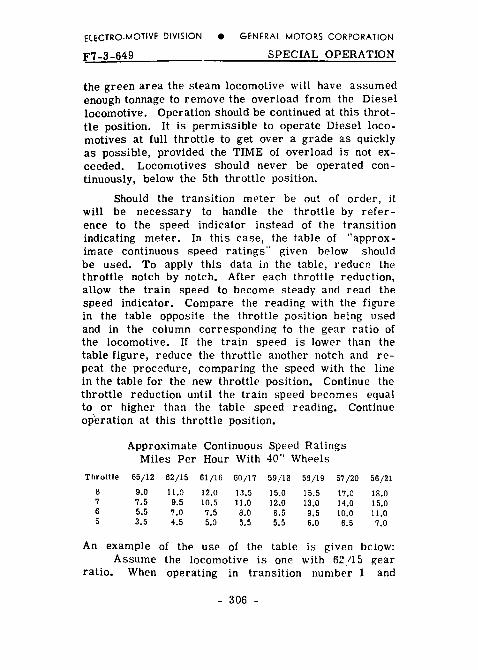
the green area the steam locomotive will have assumed enough tonnage to remove the overload from the Diesel locomotive. Operation should be continued at this throt-tle position. It is permissible to operate Diesel loco-motives at full throttle to get over a grade as quickly as possible, provided the TIME of overload is not ex-ceeded. Locomotives should never be operated con-tinuously, below the 5th throttle position.
Should the transition me>ter be out of order, it will be necessary to handle the throttle by refer-ence to the spee>d indicator instead of the transition indicating meter. In this case, the table of "approx-imate continuous speed ratings" given below should be used. To apply this data in the table, reduc2 the throttle notch by notch. After each throttle reduction, allow the train speed to become steady and read the speed indicator. Compare the reading with the figure in the table opposite the throttle position being used and in the column corresponding to the gear ratio of the locomotive. If the train speed is lower than the table figure, reduce the throttle another notch and re-peat the procedure, comparing the speed with the line in the table for the new throttle position. Continue the throttle reduction until the train speed becomes equal to or higher than the table speed reading. Continue op'eration at this throttle position.
Approximate Continuous Speed Ratings Miles Per Hour With 40" Wheels
Throttle 65/12 62/15 61/16 59/18 59/19 56/21 8 13,5 7 7.5 6 5.5 7.5 8.5 9.5 5 3.5 5.5 5.5
An example of the use of the table is given below: Assume the locomotive is one with 62115 gear
ratio. When operating in transition number 1 and
- 306 -

ELECTRO-MOTIVE DIVISION e GENERAL MOTORS CORPORATION
SPECIAL OPERATION F7-3-649
throttle in run 8, with a helper locomotive, the train speeds drops to 10 m.p.h. This is under the 11.0 m.p.h, shown in the table for a 62/15 gear ratio locomotive in throttle run 8. The locomotive is overloaded, and if the transition indicating meter were working the pointer would be to the right of No. 1 green area 1825 amp.l. The throttle is then reduced to run 7. The speed drops to 8.5 m.p.h. and the helper locomo-tive assumes more load. The locomotive is stiil over-loaded since the table shows 9.5 m.p.h. for run 7. The throttle is next moved to run 6. The speed becomes steady at 7 m.p.h. This checks with the continuous speed rating in the table and operation should be con-tinued with the throttle in this position.
308 Operating with Diesel Locomotive as Helper A number of Diesel locomotives with 12-tooth
pinions are being used in pusher or helper si!rvice. Whenever a locomotive with 12-tooth pinion is used as a pusher or helper for another locomotive having 15-tooth or larger pinions, the throttle on the 15-tooth lor larger) pinion locomotive should be handled in the same manner as when a steam locomotive helper is used. It is very desirable, as in all railroad operations, to get a train over the hill in as short a time as possi-ble, but before the TIME of overload operation is ex-ceeded, the throttle should be reduced on the locomotive with the larger pinion gears to reduce its load, putting more of the load on the locomotive with the smaller pinion. In this manner. the indicator pointer will be brought back into the safe operating zone.
At this time, the engineman on the 12-tooth pinion locomotive will have to watch his transition indicating meter to be sure his locomotive is not overloaded. If the> pointer of the 12-tooth locomotive is in the over-load zone, but the top of the hill is within the indicated mileage or time limit of the oYerload zone in which he is operating, it will be permissible to proceed, in
- 307 -

ELECTRO-MOTIVE DIVISION e GENERAL MOTORS CORPORATION
F7-3-1049 SPECIAL OPERATION
order to get over the hill in as short a time as possible, but if the TIME of overload operation is exceeded,train tonnage should be reduced. This instruction applies to any combination of locomotives with different gear ratios.
If slipping occurs, reduce throttle below the slipping point and operate sander, again opening throttle after sanders are in operation. SAND SHOULD BE USED TO PREVENT SLIPPING, NOT TO STOP IT.
309 Operating in Short Time Overload Zone When starting a train, the pointer of the transition
indicating meter will usually move temporarily into the short time overload section of the meter. This repre-sents a normal condition if the pointer return::; to the No. 1 green area as the train speed increases. If the pointer remains in the overload area or enters this section of the meter on a grade with the transition lever in No. 1 position, the locomotive is overloaded.
The locomotive is designed to stand overload oper-ation if this condition does not exceed certain limits. The greater the overload the further the pointer swings over into the overload area and the less time the locomotive can operate without the motors heating excessively.
310 Tonnage and Speed Ratings The tonnage ratings of any F7 locomotive depends on number of units,
grade, and gear ratio between the pinion on each traction motor and the axle gear with which it meshes. The table below lists tonnages for various horse power ratings and gear ratios, and also shows the approximate speed which the locomotive will develop when hauling its rated tonnage. The maximum permissible operating speed of the loco-motive for each gear ratio is also given. This repre-sents the road speed at which the traction motors will turn at the maximum safe RPM.
These minimum speeds listed below MUST NOT be used for rating the tonnage, but only as a guide to approximate the running speed with rated tonnage.
- 308 -

ELECTRO-MOTIVE DIVISION e GENERAL MOTORS CORPORATION
OPERATING PROBLEMS F7-3-35Q
With the listed tonnage ·ratings, all engines must be up to full rated output. If an engine is low in power, or an engine is "off the line,"' the tonnage should be adjusted in proportion to the decreased power.
CONTINUOUS TONNAGE RATING FIGURES FOR F7 LOCOMOTIVE
GEAR RATIO
HP GRADE 65/12 62/15 61/16 59/18 58/19 56/21
31oo 235o
Approximate Minimum For
soo
13,5 15.5
Maximum Speed 65 71 71 83 89 95
NOTE: F7 locomotives with 65/12 gear ratio and 027 motors, or 07-017 motors using armatures wound with the new silicone coils, will be per-mitted to operate at 55 MPH maximum speed. All other motors 50 MPH maximum speed.
1n order to avoid overloading the electrical equip-ment, it is important that the tonnage of the train be kept within the maximum tonnage rating limits of the locomotive except where SPECIAL TONNAGE RATING has been supplied to the railroads by the locomotive manufacturer.
- 309 -
ELECTRO-MOTIVE DIVISION e GENERAL MOTORS CORPORATION
F7-3-1049 OPERATING PROBLEMS
PROBLEMS DURING OPERATION
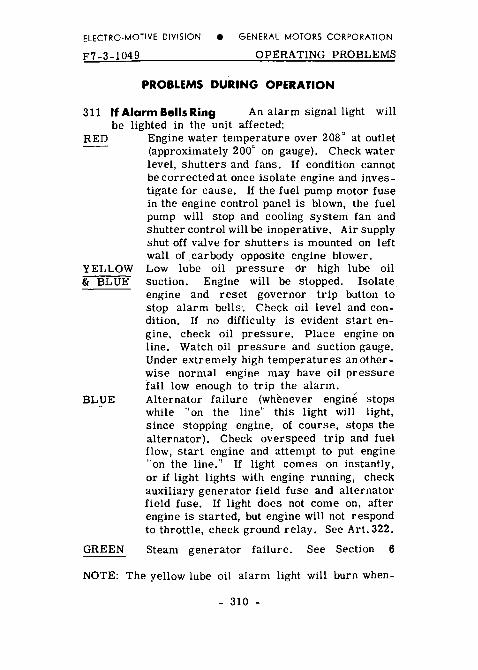
311 If Alarm Bells Ring An alarm signal light will be lighted in the unit affected:
RED Engine water temperature over 208" at outlet (approximately 200° on gauge). Check water level, shutters and fans. If condition cannot be corrected at once isolate engine and inves-tigate for cause. If the fuel pump motor fuse in the engine control panel is blown, the fuel pump will stop and cooling system fan and shutter control will be inoperative. Air supply shut off valve for shutters is mounted on left wall of car body opposite engine blower.
YELLOW Low lube oil pressure dr high lube oil & BLUE suction. Engine will be stopped. Isolate_
engine and reset governor trip button to stop alarm bells·. Check oil level and con-dition. If no difficulty is evident start en-gine, check oil pressure. Place engine on line. Watch oil pressure and suction gauge. Under extremely high temperatures an other-wise normal engine may have oil pressure fall low enough to trip the alarm.
BLUE Alternator failure (wh~never engine stops while "on the line" this light will light, since stopping engine, of course, stops the alternator). Check overspeed trip and fuel flow, start engine and attempt to put engine "on the line.'' If light comes on instantly, or if light lights with engin~ running, check auxiliary generator field fuse and alternator field fuse. If light does not come on. after engine is started, but engine will not respond to throttle, check ground relay. See Art. 322.
GREEN Steam generator failure. See Section 6
NOTE: The yellow lube oil alarm light will burn when-
- 310 -
ELECTRO-MOTIVE DIVISION e GENERAL MOTORS CORPORATION
OPERATING PROBLEMS F7-3-350
ever the governor low oil alarm switch is tripped whether isolation switch is in ·· starf' or "run" position. The ''low oil"' alarm light and" alterna-tor failure'' lights are energized through the fuel pump control circuit so that if the ··PC'' switch is tripped or the fuel pump switch in the cab pulled out or the fuel pump fuse in the operating unit is blown these alarms will not operate.
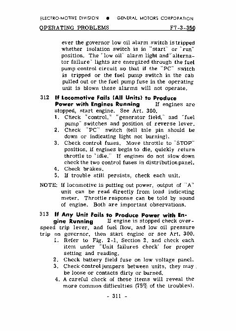
312 If Locomotive Fails (All Units) to Produce Power with Engines Running If engines are stopped, start engine. See Art. 300. 1. Check "control," "generator field," and "fuel
pump" switches and position of reverse lever. 2. Check "pc·· switch (tell tale pin should be
down or indicating light not burning). 3. Check control fuses. Move throttle to ''STOP''
position, if engines begin to die, quickly return throttle to ··idle." If engines do not slow down check the two control fuses in distribution panel.
4. Check brakes. 5. If trouble still persists, check each unit.
NOTE: If locomotive is putting out power, output of "A" unit can be read directly from load indicating meter. Throttle response can be told by sound of engine. Both are important observations.
313 If Any Unit Fails to Produce Power with En· gine Running If engine is stopped check over-
speed trip lever, and fuel flow, and low oil pressure trip on governor, then start engine or see Art. 300.
1. Refer to Fig. 2-1, Section 2, and check each item under "Unit failures check" for proper setting and reading.
2. Check battery field fuse on low voltage panel. 3. Check control jumpers between units, they may .
be loose or contacts dirty or burned. 4. A careful check of these items will reveal the
more common difficulties (75% of the troubles).
- 311 -

ELECTRO-MOTIVE DIVISION e GENERAL MOTORS CORPORATION
F7-3-350 OPERATING PROBLEMS
An unusual difficulty requires careful study of the particular situation.
Any piece of mechanical equipment is subject to some difficulties. An arrangement of protective devices is provided on these locomotives to prevent damage in case of a failure or careless operation. OVERLOADING IS ONE EXCEPTION AND IS ENTffiELY THE RESPON-SIBILITY OF THE ENGINEMAN. As soon as it is apparent that the tonnage is too great, the engineman must take the proper steps to reduce train tonnage.
In cases of serious difficulty in a unit the engine should be immediately isolated and an investigation made.
314 Isolating and Stopping an Engine while Under Power or Using Dynamic Brake (For normal stopping procedure, see Art. 3011. If it becomes necessary to take engine "off the
line" while the locomotive is operating under power, it should be done as follows:
1. Pull manual control lever shut. Hold until engine stops.
2. When bell starts ringing place the isolation switch in the ., start" position.
3. Place fuel pump switch in "OFF" position.
315 Starting and Placing Engine on the Line while Locomotive Is Under Power 1. Start engine in the usual way. (See Art.300l. 2. After lubricating oil pressure builds up, place
isolation switch in "run" position. If throttle is above third position, hold off on governor to injector linkage with layshaft manual control lever, to allow engine to come up to speed gradually. DO NOT place an engine "on the line" when using dynamic brake. See Art. 326.
- 312 -

ELECTRO-MOTIVE DIVISION e GENERAL MOTORS CORPORATION
OPERATING PROBLEMS
SPECIFIC DIFFICULTIES
316 Recovery of Control of Brake after Penalty Application
F7-3-350
1. Place automatic brake valve in "LAP." 2. Close throttle to idle. 3. Place foot on safety control foot pedal.
*4. Wait until application pipe builds up to main reservoir pressure. <Listen for exhaust or watch PC switch light - if usedi.
5. Reset train control. 6. Check PC switch. 7. Release brakes.
• If "PC'' will not reset with automatic brake valve handle in ''Lap,'' after an emergency application, place brake valve handle in running position.
317 SeHing "PC" Switch Recover brake, see Art. 316. If "PC" switch is tripped locomotive will
have power in number one throttle position (shown on load indicating meter) but engine speed will not advance as throttle is opened. Fuel pumps will be stopped. In No. 5 or No. 6 throttle position the engines will stop. No bells will ring. The ''fuel pump" switch in the cab open and the fuel pump fuse in the distribution panel blown will cause the same difficulty as a tripped "PC" switch.
318 Auxiliary Generator Charging Rate Failure of auxiliary generator will stop excitation of alter-
nator and cause a blue light. Normal output should keep battery ammeter at 0 or show some charge. Aux-iliary generator ammeter can show 20-30 amperes charge and still have 150 ampere output fuse blown. In case of auxiliary generator failure stop engine in that unit and check 30 ampere field fuse and 150 ampere output fuse.
- 313 -

ELECTRO-MOTIVE DIVISION 8 GENERAL MOTORS CORPOR,.,TION
F7-3-350 OPERATING PROBLEMS
319 Starting Contactors Main contact points must not stick closed. The interlock located underneath
main contactor must be closed and making good contact. If interlocks do not close or make contact, engine will speed up when throttle is opened but will not load. Above No. 5 throttle position the fuel indicator on the governor will be unbalanced to minimum fuel (low power piston) and load regulator will point toward 5 o'clock.
320 Control Air Control air should be 80 :t 3lbs. to supply air to close main contactors and other air
operated accessories. Failure of control air will stop power output !lS main contactors will nat close. En-gines will speed up in response to throttle. Above No. 5 throttle position, the fuel indicator will be un-balanced to minimum fuel (low power piston) and load regulator will point toward 5 o'clock. See Art. 327.
321 Battery Ammeter Battery ammeter should al-ways show 0 or some charge. If discharge is indicated
check auxiliary generator output. If trouble cannot be remedied anticipate failure as battery runs down.
322 Ground Relay Pointer points to yellow dot when set, red dot when relay is tripped. When the
ground relay is tripped the engine will not speed up when throttle is opened. In No. 5 or No. 6 throttle position engine will stop and blue light will light. To reset, isolate engine, reset relay, and put engine on line. If relay continues to trip isolate unit, Art. 324.
323 Wheel Slip Relay The wheel slip relay is lo-cated in the electrical control cabinet, behind the
power contactors. If one pair of wheels should slip while locomotive is under power, this relay w; ll pick up, lighting the wheel slip light intermittently dS the wheels slip, stop slipping and slip again, to warn the
- 314 -

ELECTRO-MOTIVE DIVISION e GENERAL MOTORS CORPORATION
OPERATING PROBLEMS F7-3-350
engineman. The throttle should be reduced to stop the slipping, and sand applied to prevent further slipping when throttle is reopened.
324 Alarm Indications For One Pair Of Wheels Sliding If one pair of wheels should slide when
starting a train, the wheel slip light will flash on and off intermittently, but as the train speed increases, the light will stay on more or less continuously and will not go out when the throttle is reduced and sand applied. The light will go out when throttle is closed to idle.
Under this condition, the engine crew should make an immediate investigation to determine the cause. The wheels may be sliding due to a locked brake, a broken gear tooth wedged between the pinion and ring gear, or a motor bearing may have seized.
Repeated ground relay action, accompanied with unusual noises such as continuous thumping or squealing, or the smell of burning paint or insulation, may be an indication of very serious traction motor trouble that should be investigated at once.
UNDER NO CONDITION OF REPEATED WHEEL SLIP INDICATION OR REPEATED GROUND RELAY ACTION SHOULD A LOCOMOTIVE UNIT OR POWER PLANT BE ISOLATED AND CONTINUED IN SERVICE WITHOUT FIRST MAKING THE ABOVE INVESTIGA-TION.
325 Engine Speed and Fuel Indicators On Governor There are two pointers on the cover of the gover-
nor. One of these pointers indicates the throttle posi-tion of the engine and is labeled "speed." The second pointer indicates the position of the power piston in 16ths of an inch and is labeled "fuel." The lower the number on the ''fuel scale" the greater the quantity
- 315 -

ELECTRO-MOTIVE DIVISION e GENERAL MOTORS CORPORATION
F7-3-350 OPERATING PROBLEMS
of fuel which is being injected into the cylinders. In No.8 throttle ''speed" position the fuel indicator needle should read between 5 and 6 if the engine is properly loaded. In general, the two pointers should be checked only in No. 8 throttle position as indications at part throttle may be misleading. If a marked variation is noted the trouble should be investigated. Excessive fuel !lower number on fuel scale> will indicate engine trouble. Minimum fuel will indicate electrical trouble.
326 Isolation Switch Isolation switch must be firmly in "run" ldownwardl position to obtain power from
the unit. The switch should be opened and closed only with engine at idle speed or stopped. Use the manual layshaft lever to bring engine to idle speed or to stop engine when the locomotive is under power or in dynamic braking. Isolation switch should NOT be placed in "RUN" position when other units are in dynamic braking unless it is KNOWN that the transition lever is in "OFF" position. The safest course is to wait until the train has stopped.
327 Load Regulator When operating in No, 8 throttle position the load regulators throughout the loco-
motive should be in approximately the same position. Extreme unbalance of the load regulator arm in one unit to maximum or minimum field is an indication of difficulty and should be investigated.
If during full throttle operation one unit shows minimum field <arm in 5 o'clock position> trouble may be either mechanical or electrical. If in maximum field <arm in 8 o'clock position> inspect for loss of electrical load.
328 Fuel Flow For proper engine operation, a good flow of fuel (clear and free of bubbles) should be
indicated in the fuel return sight glass, located on the duplex filter assembly, nearest the engine.
- 316 -

ELECTRO-MOTIVE DIVISION e GENERAL MOTORS CORPORATION
OPERATING PROBLEMS F7-3-350
Normally, a small amount of fuel will leak by the plunger, and come out the small hole in the stand pipe of the by-pass sight glass. If the leakage is enough so the fuel flows out the top of the standpipe, this fact should be reported to maintenance.
If no fuel is flowing through the fuel return sight glass check fuel pump motors and fuel pumps. If pumps in all units are stopped check "PC" switch, fuel pump switch, and fuel pump fuse in distribution panel. <Do not confuse fuel pump fuse and fuel pump motor fuse>.
If pump in other units are running, check switch on engine control panel and control switch, 80 ampere control fuse and fuel pump motor fuse in the distri-bution panel of units affected. If pump is running but no fuel is pumped check fuel supply, emergency fuel cutoff under the unit, or check for a suction leak in piping between tank and pump, also, check for broken or slipping coupling at fuel pump.
329 Overspeed Trip When tripped, fuel is stopped at the injectors and engine can not be started.
Whenever an engine is found stopped always check over-speed trip by pulling firmly on the lever (counter-clockwise) to be sure it is set. See Fig. 5-10, Sec. 5.
330 Battery Field Fuse There is an 80 ampere fuse in the battery field circuit of each main generator.
Should this fuse be blown no power will be developed in the unit affected. The battery field fuse is located on the low voltage panel which is in the electrical con-trol cabinet and is accessible through a door in the rear wall of the operating cab, and from inspection platform in "B'' unit.
331 Running through Water Under ABSOLUTELY no circumstances should the locomotive pass
through water which is deep enough to touch the bottom of the traction motor frames. When passing through
- 317 -

ELECTRO-MOTIVE DIVISION e GENERAL MOTORS CORPORATION
F7-3-350 OPERATING PROBLEMS
water, always go at a very low speed <2 to 3 miles per hour>. Water any deeper than three inches above the top of the rails is likely to cause damage to the traction motors.
332 Operation of F7 Locomotives with F 3,n,or F 2 Units In many instances it may be desirable to operate
combinations of FT, F2, F3 and F7 units in a loco-motive. This is an acceptable practice provided gear ratios are the same, and will be entirely successful if the instructions below are followed. No change in operating technique is necessary except for the con-ditions listed.
Be very careful when operating F7 units in con-junction with other units. If the F7 unit is in the lead, its transition indicator may show perfectly safe load-ing for the F7, but remember, FT, F2, and F3 units do not have as high a tonnage rating as the F7 and the F7 transition indicator will not show an overload on trailing units. Tonnage will have to be adjusted for the unit or units with the lowest tonnage rating.
1. Manual transition must be used if all units are not equipped with automatic transition. Be sure all transition cutout switches are set either all in ''automatic'' or all in "manual."
2. Throttle must be reduced to No. 6 po~ition for 2 to 3 or 3 to 2 transition when operating in manual transition position.
333 Manual Transition Should it become necessary to operate with manual transition, the transition
cutout switch marked "Auto-Man" located on the auto-matic transition panel must be set and pinned in "MAN" position. The automatic transition panel is the top panel on the left side of the electrical control cabinet. Change from automatic to manual transition operation should not be made when under power.
- 318 -

ELECTRO-MOTIVE DIVISION e GENERAL MOTORS CORPORATION
OPERATING PROBLEMS F7-3-350
It is no longer necessary to cut out the automatic transition on remaining units just because automatic transition is inoperative on one unit, or if one or more units are not so equipped; but it WILL be necessary to operate the transition lever manually, and at the proper time to effect transition on unit or units in manual position.
The throttle MUST be reduced to Run 6 BEFORE making manual transition from 2 to 3 or 3 to 2, Throttle is again opened to Run 8 after transition has been made.
334 Locomotive Units with Different Gear Ratios may be operated together ONLY under certain
conditions. It is _IMPERATIVE that the tonnage be ad-justed so the unit geared for the HIGHEST speed is not overloaded by operating below its minimum speed, and the train MUST NOT be operated at a speed higher than the top speed of the lowest geared locomotive.
- 319 -

ELECTRO-MOTIVE DIVISION e GENERAL MOTORS CORPORATION
EJ..ECTRICAL EQUIPMENT F7-3-1049
ELECTRICAL CONTROL CABINET
Location Of Panels
A. Voltage Regulator and Starting Contactors B. Low Voltage C. Automatic Transition D. High Voltage Control E. Reverser F. Traction Motor and Braking Contactors G. Dynamic Braking Control H. Low Voltage Distribution I. Cam-Switch
Detailed views of equipment on each panel are on following pages.
NOTES

ELECTRO-MOTIVE DIVISION e GENERAL MOTORS CORPORATION
F7-3-1049 ELECTRICAL EQUIPMENT
Fig. 3-2b - Cab View
Fig. 3-2c - Engine Room View (Left)
- 320 -

El ECTRO-MOTIVE DIVISION e GENERAl MOTORS CORPORATION
ELECTRICAL EQUIPMENT
Electrical Control Cabinet Panel A
F7-3-1049
Voltage Regulator and Starting Contactor Panels Fig. 3-3
1. Voltage Regulator 2. Engine Room Light Switch 3. Engine Starting Contactors 4. Starting Contactor Interlocks
- 321 -

ElECTRO-MOTIVE DIVISION e GENERAL MOTORS CORPORATION
F7-3-1049 ELECTRICAL EQUIPMENT
Electrical Control Cabinet Panel B
Low Voltage Panel Fig. 3-4
1. Reverse Current Relay (RCR) 2. VT Relay 3. Signal Relay Resistor (20 ohm) 4. Auxiliary Generator Ammeter 5. Battery Charging Contactor (BC) 6. Battery Field Discharge Resistor (4 ohm) 7. Battery Field Contactor (BF) 8. Parallel Relay (Auto. Transition Type) (PR) 9. No Voltage Relay (NVR)
- 322 -
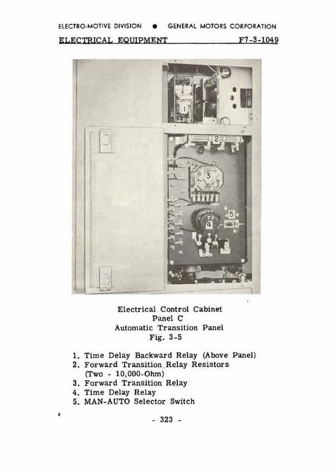
ELECTRO-MOTIVE DIVISION e GENERAL MOTORS CORPORATION
ELECTRICAL EOWPMENT
Electrical Control Cabinet Panel C
Automatic Transition Panel Fig. 3-5
F7-3-1049
1. Time Delay Backward Relay (Above Panel) 2. Forward Transition _Relay Resistors
(Two - 10,000-0hm) 3. Forward Transition Relay 4. Time Delay Relay 5. MAN-AUTO Selector Switch
- 323 -

ELECTRO-MOTIVE DIVISION e GENERAL MOTORS CORPORATION
F7-3 -1049 ELECTRICAL EQUIPMENT
Electrical Control Cabinet Panel D
High Voltage Control Equipment Fig. 3-6
1. Traction Motor Field Shunting Contactors (M) 2. 4-2000 Olun Wheel Slip Relay Resistors 3. 1-400 Ohm Generator Shunt Field Discharge
Resistor 4. 35 Ohm Resistor (In SH Operating Coil Circuit) 5. Ground Protective Relay Knife Switch (Sealed) 6. Wheel Slip Relays 7. Generator Shunt Field Contactor
- 324 -

ELECTRO-MOTIVE DIVISION e GENERAL MOTORS CORPORATION
ELECTRICAL EQUIPMENT
Electrical Control Cabinet Panel E Reverser Fig. 3-7
1. Reverser Interlocks (RVR)
F7-3-1049
2. Reverser Lock Pin (Unlocked Position) 3. Reverser (Shown in Neutral Position)
- 325 -
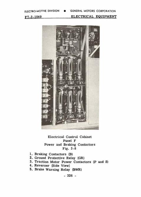
ELECTRO-MOTIVE DIVISION e GENERAL MOTORS CORPORATION
F7-3-1049 ELECTRICAL EQUIPMENT
Electrical Control Cabinet Panel F
Power and Braking Contactors Fig. 3-8
1. Braking Contactors (B) 2. Ground Protective Relay (GR) 3. Traction Motor Power Contactors (P and S) 4. Reverser (Side View) 5. Brake Warning Relay (BWR)
- 326 -

ELECTRO-MOTIVE DIVISION e GENE~Al MOTORS CORPORATION
ELECTRICAL EQUIPMENT
Electrical Control Cabinet Panel G
Relay Panel Fig. 3-9
1. Alternator Field Resistor 2. Brake Relay (BR) 3. Air Compressor Relay (CR} 4. Fuel Pump Contactor (FPC} 5. Signal Relay (SR} 6. ER Relay
F7-3-1049
7. Field Loop Contactor Location - "A" Units Only
- 327 -
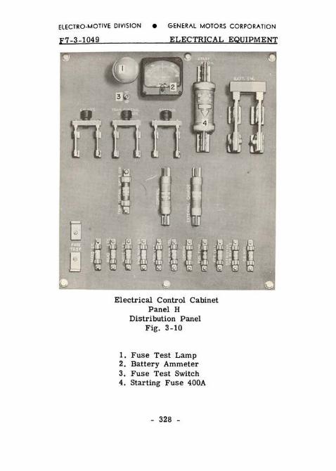
ELECTRO-MOTIVE DIVISION e GENERAL MOTORS CORPORATION
F7-3-1049 ELECTRICAL EQUIPMENT
~ 1 ~ ~tec~c,
Electrical Control Cabinet Panel H
Distribution Panel Fig. 3-10
1. Fuse Test Lamp 2. Battery Ammeter 3. Fuse Test Switch 4. Starting Fuse 400A
- 328 -

ELECTRO-MOTIVE DIVISION e GENERAL MOTORS CORPORATION
ELECTRICAL EQUIPMENT
Electrical Control Cabinet Panel I
Cam-Switch Fig. 3-11
1. Auxiliary Cam-Switch 2. Cam-Switch
F7-3-1049
3. Backward Transition Relays - BTS and BTP
- 329 -
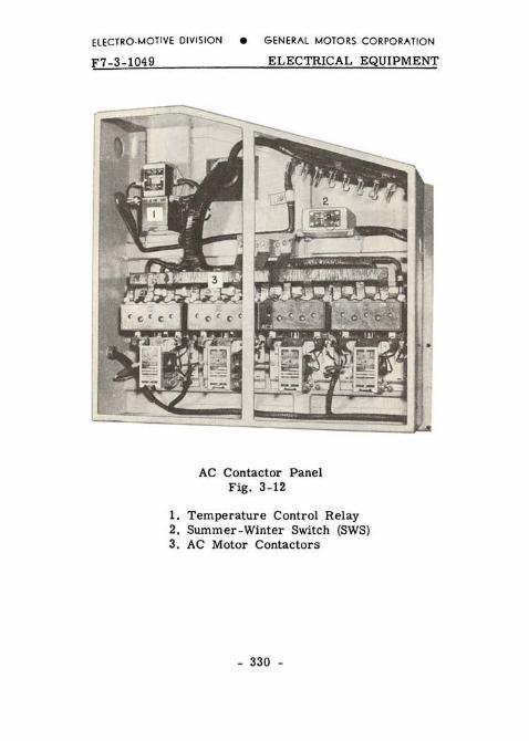
ELECTRO-MOTIVE DIVISION e GENERAL MOTORS CORPORATION
F7-3-1049 ELECTRICAL EQUIPMENT
AC Contactor Panel Fig. 3-12
1. Temperature Control Relay 2. Summer-Winter Switch (SWS) 3. AC Motor Contactors
- 330 -

ELECTRO-MOTIVE DIVISION e GENERAL MOTORS CORPORATION
EI.ECTBTCAI. F7-3-104!
Engine Control and Instrument Panel Fig. 3-13
1. Isolation Switch 2. Engine "Stop" Button 3. Fuel Pump Motor Switch 4. Engine ''Start" Button 5. Lube Oil Pressure Gauge 6. Fuel Oil Gauge (Tank Level) 7. Lube Oil Suction Gauge
- 331 -

ELECTRO-MOTIVE DIVISION e GENERAL MOTORS CORPORATION
F7-4-649
SECTION 4
COOLING, LUBRICATING OIL AND FUEL OIL SYSTEMS
COOLING SYSTEM
SYSTEMS
Water is circulated through the engine radiators and oil coolers by two pumps mounted on the engine. Cooling air through the radiator is controlled by shutters and four electrically driven cooling fans. The operation of the fans and shutters is entirely automatic and under normal conditions will hold the temperature of the engine cooling water so that the gauge on the inlet of left water pump will read in the green area (120" - 190").
In the event of excessive cooling water temperature the high temperature alarm switch will close causing a red light to show in the unit affected and the alarm bells to ring in all units.
400 Operating Water Level Operating water levels are stenciled on the water tank next to the water
gauge glasses to indicate minimum and maximum water levels with engine running and stopped. The engine should never be operated with the water below the low water level. Progressive lowering of the water in the gauge glasses indicates a leak in the cooling system and should be reported.
The system is filled either through the filler pipe located on the roof of the locomotive above the water tank, or through the filler pipe at the rear of the unit on either side.
To fill the system proceed as follows: 1. Stop engine. 2. Open filling level valve "G." 3. Fill slowly until water runs out filling level
pipe at valve "G."
- 400 -

ELECTRO-MOTIVE DIVISION e GENERAL MOTORS CORPORATION
SVSTEMS F7-4-249
4. Close filling level valve "G."
If filling a dry or nearly dry engine also follow these additional steps: 5. Start engine and run several minutes. This
will eliminate any air pockets in the system. 6. Shut down engine and open valve "G," and wait
3 minutes. 7. Add water until it runs out filling level pipe. 8. Close filling level valve "G."
If the cooling system of a hot engine has been drained, do not refill immediately with cold water. If this is done, the sudden change in temperature might crack or warp the cylinder liners and heads.
CAUTION: 1. Do not attempt to fill the cooling sys-tem through the drain pipe located un-derneath the locomotive.
2. The system should not be filled above the maximum water level indicated on the water tank. a. To prevent freezing of radiators in
winter. b. To prevent loss of rust inhibitor
when draining back to "G" valve level.
LUBRICATING OIL SYSTEM Oil under pressure is forced through the engine
for lubrication and piston cooling by the combination piston cooling and lube oil pump.- Lube oil which falls into the oil pan is picked up by the scavenging oil pump and forced through the oil filters and cooler to the oil strainer housing where it is ready for recirculation by the oil pump. The excess returns to the oil pan where it is held until used.
- 401 -

ELECTRO-MOTIVE DIVISION e GENERAL MOTORS CORPORATION
F7-4-1049 SYSTEMS
401 Oil Level The oil level may be checked with the engine running at any speed and should read
between "low" and "full" on either bayonet gauge <one on each side of engine). When the engine is stopped the oil from the filter and cooler will drain back into the oil pan and the level on the dipstick should show 11 system charged. 11 The mark "system uncharged" is used by maintenance forces when filling oil pan when new on filter elements are installed.
402 Adding Oil to System When oil is added to the system, it must be poured through thP opening
having the square cap on top of the strainer housing. Should the round caps be removed while the engine is running, hot oil under pressure will come from the openings and possibly cause personal injury.
When the engine is stopped, all the oil in the cooler core chamber will drain into the strainer cham-ber and then overflow into the engine oil pan, which will bring the engine oil pan bayonet gauge reading to "system charged." This level is below the "system un-charged" level because some oil is trapped in the lube oil filter, oil lines and engine.
403 Oil Pressure Oil pressure at 800 RPM is nor-mally 35 to 45 pounds. It should not drop below
20 pounds. At idle the pressure should be at least 6 pounds. <In the event of dangerously low oil pressure the engines will automatically be stopped).
FUEL OIL SYSTEM Fuel in each unit is circulated through the in-
jectors by an electric driven fuel pump. Failure of pump to operate, closed emergency fuel cutoff valve, or clogged strainer can cause fuel failure - See Sec-tion 5 of this manual.
- 402 -

ELECTRO-MOTIVE DIVISION e GENERAL MOTORS CORPORATION
SYSTEMS F7-4-1049
404 Filling Fuel Tanks The fuel tanks can be filled from either side of the locomotive at a
maximum rate of 250 gallons per minute due to baffles and vents in the tank. Direct reading sight level gauges located on each side of the fuel tank adjoining the fuel fillers indicate level of fuel oil starting at 4-1/2" from the top of the tank and should be observed while filling the tank to prevent overflowing. The fuel should be filtered through a reliable fuel filter before it enters the tank. The fuel capacity of each tank is 1200 gallons. DO NOT HANDLE FUEL OIL NEAR AN OPEN FLAME.
405 Fuel Gauge located on engine control and instru-ment panel in engine room is a direct reading, air
operated gauge which indicates quantity of oil in the fuel tank. The gauge does not show fuel level continuously; a push-button needle valve directly below the fuel gauge must be pushed in to get fuel level indication on gauge.
406 EmergencyFueiCutotfValve An "Emer-gency Fuel Cutoff Valve" is provided to cut off the
fuel supply to the fuel pump in the event of fire, or any emergency. It is located in the center of the underside of the fuel tank inside a valve compartment on which is a sliding cover. On each side of the locomotive, both "A" and "B" unit, attached to the side skirt, is a small box with a lift cover. Enclosed in this box is a pull ring on the end of the cable running to the fuel cutoff valve. A similar ring is located in the operating cab of each "A" unit, and one on the engineroom wall at the governor end of the engine in each "B'' unit.
The fuel cutoff valve can be tripped, and the fuel cut off by pulling any one of these rings. If tripped, the valve underneath the fuel tank must be reset manually.
To reset: crawl under locomotive fuel tank, and slide valve compartment cover to one side. Pull valve stem out and set yoke in place to hold valve open. Close valve compartment cover. See Fig. 5-9 - Sec. 5.
- 403 -

ELECTRO-MOTIVE DIVISION e GENERAL MOTORS CORPORATION
F7-5-1049 TROUBLE SHOOTING
SECTION 5
ON- THE- ROAD TROUBLE-SHOOTING
This section is a reprint of the original issue of the "On-the-Road Trouble Shooting" booklet which has met with much approval among railroad personnel.
It provides a check list call-ing the Operator's attention to the troubles which are most frequently encountered on the road, and which can be quickly remedied thereby eliminating many delays.
No attempt is made to explain general operation and functions of equipment on the locomotive. For such information refer to the first five sections of this manual.
- 500 -
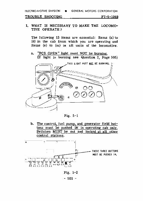
ELECTRO-MOTIVE DIVISION e GENERAL MOTORS CORPORATION
TROUBLE SHOOTING F7-5-1049
1. WHAT IS NECESSARY TO MAKE THE LOCOMO-TIVE OPERATE?
The following 13 items are essential: Items (a) to (d) in the cab from which you are operating and items (e) to (m) in all units of the locomotive.
a. "PCS OPEN" light must NOT be burning. (If light is burning see Question 2, Page 505)
\
Fig. 5-1
b. The control, fuel pump, and generator field but-tons must be pushed IN in operating cab only. Switches MUST be out and locked at all other control stations.
I THREE
BE
Fig. 5-2
- 501 -

ELECTRO-MOTIVE DIVISION e GENERAL MOTORS CORPORATION
F7-5-1049 TROUBLE SHOOTING
c. The engineman's reverse lever must be in the forward or reverse position and transition lever in No. 1 position.
d. All the brakes must be released.
e. All switches in each distribution panel must be closed (Fig. 5-3).
THE FUSES MARKED "X" SHOULD BE TESTED TO BE SURE THEY ARE GOOD.
IF THIS AMMETER SHOWS A DISCHARGE WHEN ENGINE IS RUNNING, CHECK AUX. GEN. CHARGING FUSE (FIG. 5-8, PAuE 505).
D
A
THE R
READ
Fig. 5-3
f. There must be approximately 80 pounds of control air pressure on the gauge next to each distribution panel. (If no pressure or incorrect pressure, see Question 10, Page 510.)
- 502 -

ELECTRO-MOTIVE DIVISION e GENERAL MOTORS CORPORATION
TROUBLE SHOOTING F7-5-1049
g. Fuel pumps in all units must be running and fuel flowing through sight glasses. (If not refer to Questions 5 & 6 on Pages 506 & 507.)
FUEL BE MG
TH -BUT THE
Fig. 5-4
h. The engines must be running. (If stopped refer to Question 7,
i. The isolation switches must be in position.
_L---- READ FUEL GAUGE
BE GET FUEL RUN.
THE HANDLE BE
Fig. 5-5
- 503 -
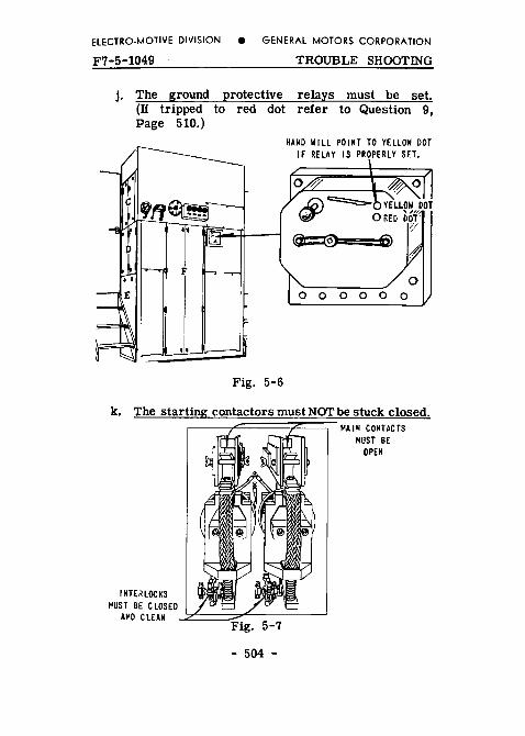
ELECTRO-MOTIVE DIVISION e GENERAL MOTORS CORPORATION
F7·5-1049 TROUBLE SHOOTING
j. The ground protective relays must be set. (If tripped to red dot refer to Question 9, Page 510.)
Fig. 5-6
HAND WILL POINT TO YELLOW DOT IF RELAY IS PROPERLY SET.
k. The starting contactors must NOT be stuck closed.
BE
- 504 -
BE

ELECTRO-MOTIVE DIVISION e GENERAL MOTORS CORPORATION
TROUBLE SHOO!ING F7-5-1049
1. Battery field fuses in all units must be good.
THIS IS AMP. F FUSE
Fig. 5-8
m. Be sure that all hand brakes are fully released,
2. CAN I MAKE THE OPEN" LIGHT GO OUT?
The "PCS Open" light is caused to burn only by an emergency or a penalty application of the brakes. By a penalty application, we mean one caused by removing your foot from the safety control foot pedal, overspeeding the locomotive, or application caused by train control devices.
- 505 -

ELECTRO-MOTIVE DIVISION e GENERAL MOTORS CORPORATION
F7-5-1049 TROUBLE SHOOTm·G
To get the light to go out, a good procedure is to be sure the throttle is in "idle" position and then take whatever steps are necessary to fully release the automatic brake.
If the brakes are applied in "Service," the brake valve may be placed in lap and left there until the light goes out. If there has been an emergency application, the brake valve must be lapped and then moved to running position before the light will go out.
3. IF I DO NOT GET THE "PCS OPEN" LIGHT TO GO OUT WHAT WILL HAPPEN?
Engines will idle for about five minutes, but after that the engines may stop for lack of fuel since when the "PCS Open" light is burning all the fuel pumps in the locomotive are stopped.
4. IF AN ENGINE STOPS WHEN THE "PCS OPEN" LIGHT IS BURNING: WILL THE BLUE LIGHT COME ON AND THE ALARM BELLS RING?
No.
5. IF THE FUEL PUMP IS NOT RUNNING WHAT CAN BE DONE?
Check other pumps in the locomotive to see if they are running. If all the fuel pumps are stopped, check the items shown on Figures 5-l, 5-2 and 5-3 in this section.
If only the fuel pump in one unit is stopped, be sure the switch on the engine control panel (Fig. 5-5) is turned on and the control and fuel pump motor fuses in that unit (see Fig. 5-3) are O.K.
- 506 -

ELECTRO-MOTIVE DIVISION e GENERAL MOTORS CORPORATION
TROUBLE SHOOTING F7-5-1049
6. IF THE FUEL PUMP IS RUNNING BUT FUEL DOES Nai' SHOW IN THE FUEL RETURN SIGHT GLASS (Fig. 5-4) WHAT CAN BE DONE?
If fuel is flowing in the other glass (45 pound) next to the return sight glass, the fuel filters are clogged and nothing can be done on the road.
If no fuel is flowing in either glass, check fuel supply in tank; check to see that the emergency fuel cutoff valve under the locomotive fuel tank has not been tripped (see Fig. 5-9). If this valve is properly set the suction strainers may be clogged and if tools are available, the Wastex may be re-moved and the filter element replaced without any Wastex.
FUEL TANK SUMP
Fig. 5-9
- 507 -

ELECTRO-MOTIVE DIVISION e GENERAL MOTORS CORPORATION
F7-5-1049 TROUBLE SHOOTING
7. IFIFINDANENGINE STOPPED WHAT SHALL IDO?
Pull the isolation switch handle up into "START" position (Fig. 5-5). Make certain the switches on the distribution panel in this unit are closed and the fuses good (Fig. 5-3).
Then be sure fuel pump switch is "ON" (Fig. 5-5), and check the fuel return sight glass for a good flow of fuel (Fig. 5-4).
Look at the overspeed trip lever and move it counter-clockwise to be sure it is "set" (Fig. 5-10).
I
-, : :;
' \ !. ' -- .. ' : \
) \ : /
Fig.
Be sure the low oil pressure trip button on the governor is pushed in so the red part of the shaft is not showing (Fig. 5-11). Hold the layshaft part way open and start the engine by pressing on the "START" button. Check the ground
rotective relay (Fig. 5-6) and the starting contactors Fig. 5-7 and then put the isolation switch down in
- 508 -

ELECTRO-MOTIVE DIVISION e GENERAL MOTORS CORPORATION
TROUBLE SHOOTING F7-5-1049
"Run" position, if engine throttle is in #2 position or lower. If throttle is in #3 position or higher, hold back on layshaft lever to prevent surge in engine speed.
EN& I NE GOVERNOR
\ p 6
TRIP BUTTON
Fig. 5-11
- -

GENERAL MOTORS CORPORATION
F7-5-1049 TROUBLE SHOOTING
8. HOW CAN I TELL IF AN ENGINE IS PUTTING OUT POWER?
When the engineer has the throttle in Run 8 pulling a train, the plate on the governor should appear as in Fig. 5-11. If the right hand scale does not read 8 but reads idle, the isolation switch may not be in "RUN" or the ground protective relay may be tripped. If the right hand scale shows 8 but the number on the left hand scale reads 8 to 10, the engine is not loaded and there is probably electrical trouble. Check the bat-tery field fuse; it may be blown <See Fig. 5-Sl or the control air <Fig. 5-3! may be low.
If this does not correct the condition, have the engineer reduce the throttle to "idle" momentarily and then return it to Run 8 and check the scales on the gover-nor plate again.
9. HOW IS GROUND PROTECTIVE RELAY SET?
Isolate the engine, press on ground protective relay set button <Fig. 5-6l, then place isolation switch firmly in "RUN" position. If ground protective relay continues to trip, isolate engine and shut down.
10. HOW CAN I GET CONTROL AIR PRESSURE ON GAUGE?
Control air pressure may be shut off at piping to con-trol air regulator, the regulator may be set too low (turn knob on top clockwise to raise pressure!, or air may be shut off at valve in control cabinet. Control air comes from main reservoir so main reservoir pressure must be up. Pressure on gauge should be at least 70 pounds. Control air pressure as high as main reservoir is acceptable in an emergency. The correct setting is 80 pounds.

ELECTRO-MOTIVE DIVISION e GENERAL MOTORS CORPORATION
TROUBLE SHOOTING F7-5-1049
"Run" position, if engine throttle is in #2 position or lower. If throttle is in #3 position or higher, hold back on layshaft lever to prevent surge in engine speed.
EN& INE GOVERNOR
PUSH
Fig. 5-11
- -

e GENERAL MOTORS CORPORATION
F7-5-1049 TROUBLE SHOOTING
8. HOW CAN I TELL IF AN ENGINE IS PUTTING OUT POWER?
When the engineer has the throttle in Run 8 pulling a train, the plate on the governor should appear as in Fig. 5-11. If the right hand scale does not read 8 but reads idle, the isolation switch may not be in "RUN" or the ground protective relay may be tripped. If the right hand scale shows 8 but the number on the left hand scale reads 8 to 10, the engine is not loaded and there is probably electrical trouble. Check the bat-tery field fuse; it may be blown (See Fig. 5-81 or the control air (Fig. 5-31 may be low.
If this does not correct the condition, have the engineer reduce the throttle to "idle" momentarily and then return it to Run 8 and check the scales on the gover-nor plate again.
9. HOW IS GROUND PROTECTIVE RELAY SET?
Isolate the engine, press on ground protective relay set button <Fig. 5-61, then place isolation switch firmly in "RUN" position. If ground protective relay continues to trip, isolate engine and shut down.
10. HOW CAN I GET CONTROL Affi PRESSURE ON GAUGE?
Control air pressure may be shut off at piping to con-trol air regulator, the regulator may be set too low <turn knob on top clockwise to raise pressure>, or air may be shut off at valve in control cabinet. Control air comes from main reservoir so main reservoir pressure must be up. Pressure on gauge should be at least 70 pounds. Control air pressure as high as main reservoir is acceptable in an emergency. The correct setting is 80 pounds.
- 510 -
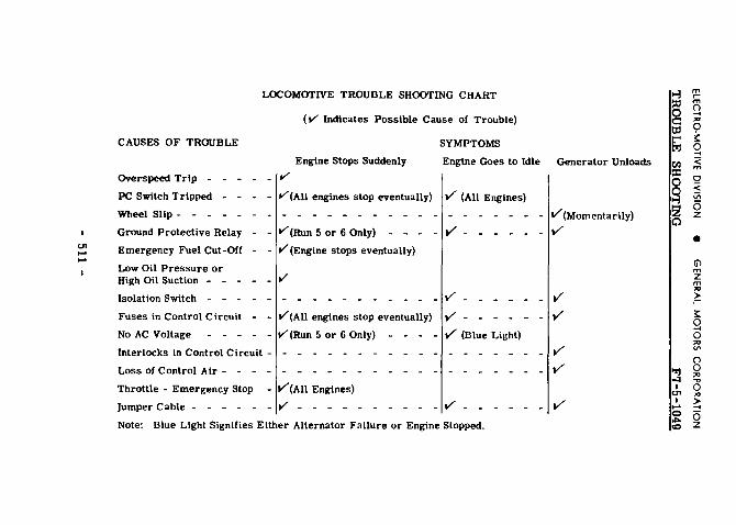
TROUBLE CHART
( Indicates Possible Cause of Trouble)
Engine Engine Goes to Idle Generator Unloads Overspeed Trip -
PC Tripped
Wheel - - -
(All stop eventually) (All Engines)
Ground Protective Relay - - (Run 5 or 6 Only)
Emergency Fuel Cut-Off - - (Engine stops eventually)
Low Oil Pressure or High Oil - - - - -
- -
Isolation - - ---- -- ___
Fuses in Control Circuit -
No AC Voltage - - - -- (All engines stop eventually) -- 5 or 6 Only) - - - - (Blue Light)
Interlocks in Control Circuit - - -
Loss of Control Air - - - -' - -
_
- -
Throttle - Emergency Engines)
Jumper Cable - - - - - - - - - - - - - - - - - - - - -Note: Blue Light Either Alternator Failure or Engine
m m ()
m
<
z
m z m
()
z


->
....
2.
-
-tl.
On
21. ou
E
--
- noo
- r
-
--
- lA
-
ou -
..
.. -
r --
m
m
z
m z m
>
8
z

GENERAL
General Arrangement, Drains and Fillers - "A" Unit Chart A - Part 2

f -
....
...
I. Hom t'A' Ull!tzl 0!1.1)'1 2. Drum~" Dnlw Gr1da ullll Blow•n l, CooUac F111 ... li&gl:or 4. Air lalU.e lor GrtU &lid E/WIIW floolll ~- Air Lnbb ud Srlo!U.n II. Carbodr Air Fillers 1, BaU.ry 8o• - DoUa SJ4u Uadu C;~rtoady I.MalftAtr~l""olr II. J\11! Tank G;flllll - DaO!. Sldn Ill 8W. Skirts
10. hd Tar* - Urdu Carbod:y 11. Emerw:-l' ~I C"otf Pu.U R1IIJ.. 0.. ~ILI.ri,IINI4
aldl of t.t tank, both •*• fll. aalt. Oae pull rlfl& '" aptnta,. ub. rA" U•n.~ Ontrl
E~~~e....-cr Fuel ~toef PloU ftt.,. a.. sllll1, .,,. a..r.oft ... tta'*boUI•~' Oil lllllL On. nne aa leU •"'PM tooa wall o..-lte n.dM a:-er· nor. CB" l!alta Only)
ll. Tnc-11"" Mll'W>r BJc,.., 13. Elt'Ctrlul Coootrol Calnnn U. AlrCmapna.ao.r U. Mud Bralll 18. a. ... ,,.,, lllawtor
11. A11&1U.ry GnJntar II .... ta Gnerator ud Ahenwor lt .... llt-M'JBI!!IIfllle JO. ~I Ta.alt v,., W'l.lb Flame Ar"""lor J:l, "-dLatar, COCIU.. U . ._.be OU CoolPr 23. i._.s Jbop ... ,., .. 24.. I:.P• Coe~trol ud lut111-•t Pufl U, ~ Coolln& W:ot.,. ,.. ... 2f.l.ube01o1FIIter J1. llwlll'l QIMntDI' Water Sclft .. ltr 21. ltlol;;un O..ntor - 1100 Lb. CIPICLtp n. &.am ae-utor w,aer TIUIII: - 200 GIL Tanll
1111!1 1800 Lb. Ilea• C..ntu SO. Air Bn.k• l:qr;a.lplllftl ("8' Ullita Dilly) 31, a.,.,., Go!-niOI' Wa&e>r Tu.ll lor Llll"'• llnlllo
~nton - JZOO GaL f'B. u ..... O..ly\ 31.. SUd Bm. ud FlUtr - T-o • Eadl &me cl Car 33. llllnery Cbar~ClfW RH.,..cle- t.tt SI.S. O..lr '"· E,..U.1t A.lr Boa Dn111 - BoUa Sldu Uader Cu·
body, Vahtu 11 Eaello St4l ol Enf:U.• Uftller Oil hll Haldlalr Conn~ Noe, 1 a.t U
SS. r..a Tulr. ..,, .. , Dnla Vah'rl - 8otlr. Sldn I• 1'-* Srlllllp
H. n.ITafllr. SampDraUI Plill- LDTilllll ~~~ n. f'WI TUII! Dtl.ill Plu1 - Ia BoCIOIII Ill Toll la111p :tll,h•IPU .. r- &nctlSJdooai.DSidfllkln
iZ·l/:ll""lPIIJ H. Ellea. !IV111p Dtl Dnla - Litlt &de, Val..,. &lid
Onla Ulldn Cu!:lody 40. I..Mbit 011 Fllllr ,I. EIIC*M Wa,.r Dnla- Ulldu Ca~. Valve Inawt.
c ..... , U. E..P111t OU Stnwr Dnla- Lell a ... u.a.r Car·
boiJ, VaM IllUde Cartlody U. Roof Water P"lller \I:"'IMI - On Rom" CJI Car
aboft £11f1M COCII ... W.ttn Taa -44. 91UIII GnleralOr W~llr T.t. Filkor - 8oth S1U•
lllllhf C..naty .tl Rt&r af Car 1200 Uld 300 GaL T .. b Oll.ly)
<1$. E..,a.,e W•lllr Ftlllt - Both S1drs U11d1tt Catbody •t tb'ar"' car
46. 81111111 G-t11.ar Wololltt Taalt Fll .. r - Both llele• - 12011 Gal. Tallll. 1"8" Un..tl8 Only\
m r-m
~ "' 0 ~ 0 .... < m 0 < iii 6 z
• (i'l m z m "' > r-~
§ "' VI
8 "' ..., 0 "' ~ 6 z

ELECTRO-MOTIVE DIVISION e GENERAL MOTORS CORPORATION
General Arrangement, Drains and Fillers - ''B" Unit Chart B - Part 2

NOTES

ELECTRO-MOTIVE DIVISION e GENERAL MOTORS CORPORATION
F7-6-1049 STEAM GENERATOR
SECTION 6
STEAM GENERATOR OK-4630, OK-4625, OK-4616
INTRODUCTION
The instructions contained in this section are for the guidance of personnel engaged in the operation of OK series steam generators. A general description of the steam generator is given, the operating technique is outlined and a trouble shooting section is provided for the operator.
The symbol number after each device mentioned in the text refers to the schematic operating chart at the end of this section. The numbers are used to facilitate identification of the various devices.
The chart shows the various controls and devices on the OK series of steam generators and outlines the flow of fuel, water and steam.
DESCRIPTION
Steam generators of the 4630 series have a rated capacity of 3000 pounds of water evaporation per hour; 4625 steam generators have a rated evaporative capac-ity of 2500 pounds per hour; and 4616 steam generators have a capacity of 1600 pounds per hour. Operation is completely automatic after the steam generator is started, and full operating steam pressure is reached within a few minutes.
The steam generating part of the unit consists of three sets of coiled water tubing, nested and con-nected in series to form a single tube several hundred feet long. Water is pumped into the coil inlet and con-
- 600 -

Fig. 6-1 OK-4360 Vapor-Clarkson Steam Generator
- 601 -

ELECTRO-MOTIVE DIVISION e GENERAL MOTORS CORPORATION
F7-6-1049 STEAM GENERATOR
verted to steam as it progresses through the coils. Heat is furnished by the combustion of diesel fuel oil, which is sprayed by compressed air through the atom-izing nozzle in the fuel spray head-105 into the firepot above the coils. Here the fine oil spray mixes with air supplied by the blower-202, and is ignited by a continuous electric spark-220. The fire and hot gases flow, first downward, then outward through the nest of coils.
The supply of fuel is regulated to evaporate 90% to 95% of the water pumped through the coils. The excess water flushes scale and sludge from the coils and is carried over with the steam into the steam separator-221, where the water and sludge are re-moved before the steam flows into the trainline.
The excess water collects in the bottom of the steam separator. Water above the level of the return outlet flows out through a steam trap-223 and through the heat exchanger-213, where it gives up its heat to the incoming feed water. From the heat exchanger the return water flows through return water flow in-dicator-218 back to the water supply tank-232.
The motor converter-215 drives the blower-202, water pump-230 and fuel pump-209 at a constant speed. The water by-pass regulator-111 automatically controls steam generator output by regulating the amount of water fed to the coils. Before entering the coils, the water passes through servo-fuel control-lOB, which ad-mits fuel to the spray nozzle in direct proportion to the amount of water entering the coils. The servo-fuel control also adjusts the damper-203 to admit the proper amount of air for efficient combustion of the fuel.
The trainline steam pressure is regulated by ad-justing the handwheel on the water by-pass regulator-111. The length of train and the weather conditions determine the setting.
- 602 -

ELECTRO-MOTIVE DIVISION e GENERAL MOTORS CORPORATION
STEAM GENERATOR F7-6-1049
BEFORE STARTING
On OK models, the valves designated by odd numbers must be OPEN during normal operation of the steam generator. Valves designated by even num-vers must be CLOSED during normal operation of the steam generator. Normally open valves are fitted with a cross type handle; normally closed valves are fitted with the standard round handle.
1. Make certain that the following valves are OPEN:
Atomizing Air Shutoff Valve-1 Coil Shutoff Valve-3 Return Water Outlet Valve-9 Steam Admission Valve-~1 to Trainline Pressure
Gauge-224 Steam Admission Valve-13 to Water By-Pass Regu-
lator-Ill Three-Way Washout Valve-17 Water By-Pass Regulator Shutoff Valve-19 Water Supply Stop Valve-21
2. Be sure that the following valves are CLOSED:
Coil Blowdown Valve-2 Layover Connection Shutoff Valve-6 Manual Water By-Pass Valve-8 Steam Admission Vdve-10 to Radiation-217 Washout Inlet Valves-14 and 16 Water Pump Test Valve-18 Water Drain Valves-20 and 22
3. See that both the overload reset button-106 and the stack switch-109 reset button are "in." The over-load reset button is located inside the control panel on the magnetic overload relay.
- 603 -

ELECTRO-MOTIVE DIVISION e GENERAL MOTORS CORPORATION
F7-6-1049 STEAM GENERATOR
TO FILL
1. Open the atomizing atr shutoff valve-1 and fill-test valve-4; latch open the separator blowdown valve-12 to drain the steam sep-arator. Close the separa-tor blowdown valve when the separator is com-pletely drained.
2. Close the main switch and turn the control switch -102 to FILL.
3. While the coils are ftlling see that spark-220 is avail-able for ignition. Check ALL valves.
4. When water discharges from the fill-test valve-4 turn the control switch-102 to OFF and close the !HI-test valve.
NOTE: If the coils are empty It will take about five min-utes to fill the steam gen-erator with water.
TO START
Steam Separator on OK-4630 Fig. 6-2
CAUTION: Do not start the steam generator unless the coils are filled.
1. Latch open the separator blowdown valve-12 and turn the control switch-102 to RUN. (For easy starting, be sure the control switch has been· OFF
- 604 -

ELECTRO-MOTIVE DIVISION e GENERAL MOTORS CORPORATION
STEAM GENERATOR F7- 6-1049
long enough for the motor to come to a full stop.)
2. Close the separator blowdown valve when the gen-erator steam pressure gauge-212 registers 50 lbs.
3. Open the separator blowdown valve several times for three to five second intervals during the first few minutes of operation.
4. Set the water by-pass regulator-Ill to the required trainline pressure.
5. After the trainline is coupled, open the remote control trainline shutoff valve-7 by depressing the reset lever-7a. Then open the stop and check valve-15.
NOTES:
1. Check the return water flow after the steam gen-erator has settled down to a steady output. On 3000 lb. units the return water flow indicator-218 should cycle from 4 to 12 times a minute; on 2500 lb. units it should cycle from 4 to 10 times a minute; and on 1600 lb. units frc.m 4 to 8 times a minute.
Return Water Flow Indicator
Fig. 6- 3
2. If the steam generator does not start or function properly, check all valves to see that they are open or closed as indicated in the operation chart.
3. The steam generator should come up to full operating pressure in one or two minutes; it may take 10 to 15 minutes to build up the required operating steam pres-sure in the trainline. - 605 -
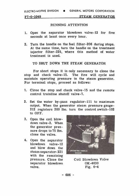
ELECTRO-MOTIVE DIVISION e GENERAL MOTORS CORPORATION
F7-6-1049 STEAM GENERATOR
RUNNING ATTENTION
1. Open the separator blowdown valve-12 for five seconds at least once every hour.
2. Turn the handle on the fuel filter-206 during stops. At the same time, turn the handle on the treatment injector filter-225, where this method of water treatment is used.
TO SHUT DOWN THE STEAM GENERATOR
For short stops it is only necessary to close the stop and check valve-15. The fire will cycle and maintain operating pressure in the steam generator. For terminal stops, proceed as follows:
1. Close the stop and check valve-15 and the remote control trainline shutoff valve-7.
2. Set the water by-pass regulator-Ill to maximum output. When the generator steam pressure gauge-212 registers 200 lbs. turn the control switch-102 to OFF.
3. Open the coil blow-down valve-2. When the generator pres-sure drops to 75 lbs. close the valve.
4. Open the separator blowdown valve-12 and blow down the steam separator- 221 with the remaining pressure. Close the separator blowdown valve.
- 606 -
Coil Blowdown Valve OK-4630 Fig. 6- 4

ELECTRO-MOTIVE DIVISION e GENERAL MOTORS CORPORATION
STEAM GENERATOR F7-6-1049
5. Fill the coils with water.
6. Close the atomizing air shutoff valve-1 and open the main switch.
NOTE: When starting, do not omit draining the steam separator, opening the fill-test valve, and again filling the steam generator with water. If the coils are already full, it will only take a moment for water to discharge from the fill-test valve.
FREEZING WEATHER PRECAUTIONS
The inlet valve-10 to the radiation-217 should be opened when operating during severe weather.
If a locomotive with a multiple installation does not have all of its steam generators in operation, open the coil blowdown valve-2, the layover connection shut-off valve-6 and the inlet valve-10 to the radiation on idle steam generators.
CAUTION: Layover connection shutoff valve-6 must be closed when trainline shutoff valve-7 is closed to cut a car out of a train.
If a locomotive is left standing out of service, operate one of the steam generators or make a con-nection to the yard steam line. In extremely cold weather the water pump-230 and steam generator con-trols should be given additional protection against freezing.
If no steam at all is available, thoroughly drain the steam generator. Open the drain valves-20 and 22,
- 607 -

ELECTRO-MOTIVE DIVISION e GENERAL MOTORS CORPORATION
F7-6-1049 ST EAM GENERATOR
the water pump test valve-18, the coil blowdown valve-2, the separator blowdown valve-12 and the coil shutoff valve-3. Break the pipe connections where necessary to completely drain the piping. Turn the water pump by hand to clear it of water, or blow it out with compressed air. Remove the cover of the water trea~ment or water strainer tank-234 and make sure it is drained.
TROUBLE SHOOTING
U one of the protective switches (magnetic over-load relay, coil blowdQwn valve switch, stack switch high temperature contacts or low temperature contacts) operates to shut down the steam generator , the alarm will ring and the 'boiler off' signal will flash on the remote control panel.
Turn the control switch-102 to OFF and use the followtng instructions as a guide in locating the trouble.
Control Panel on OK-4630 Fig. 6- 5
- 608 -

ELECTRO-MOTIVE DIVISION e GENERAL MOTORS CORPORATION
STEAM GENERA TOR F7-6-1049
Motor and Burner Shut Down During Operation
1. Blown fuses: The alarm will not ring and the in-strument lights will go out. The main fuse (or circuit breaker) is generally located in the low voltage cabinet of the locomotive. Check this fuse, and check the control fuses in the steam generator control cabinet. A test lamp and fuse clips wired inside the control cabinet may be used to check the fuses.
2. Overload reset button-106 "out:" The alarm will ring; the Instrument lights will remain on. Turn the control switch-102 OFF: check for hot blower-202 or water pump-230 bearings and for poorly adjusted pulley belts. Check the setting of the belt tension adjuster. Push the overload reset button "in."
3. Stack switch•109 reset button "out:" The high tem-perature contacts in the stack switch are open; the alarm will ring and the instrument lights will
Stack Switch Fig. 6-6
- 609 -
remain on. Turn the control switch-102 to OFF; open the separator blow-down valve-12 and drain thesteam sep-arator-221. Close the separator blow-down valve, push in the stack switch re-set button, refill the coils with water, and then start the steam generator.
4. Coil blowdown valve-2 partially open:

ELECTRO-MOTIVE DIVISION e GENERAL MOTORS CORPORATION
F7-6-1049 STEAM GENERATOR
The alarm will ring, the instrument lights will remain on. Be sure the locking pin on the coil blowdown valve handle is properly seated in the closed position.
Motor Starts But Burner Does Not
If the fire fails to light, the low temperature contacts on the stack switch-109 will not close, and after a 45 second time delay the outfire relay will open the circuit to shut down the steam generator. The alarm will ring and the instrument lights will remain on. Turn the control switch-102 OFF and check the following list for possible causes for the burner failure.
1. Ignition failure: Turn control switch to RUN-no spark visible through the peep hole glass, or spark is of low intensity. If an ignition fuse is blown or if the current flow is broken for any other reason, the ammeter in the ignition circuit registers zero when the ammeter test button is pressed in. If the ammeter registers below normal, the spark plug electrodes are dirty or too far apart. If the ammeter registers above normal the electrodes are too close together, or the ignition circuit is grounded.
Check the ignition fuses-use the test lamp and clips installed in the control cabinet for that pur-pose. Tighten loose cable connections and replace chafed or broken wire which may be breaking or grounding the circuit.
2. Low atomizing air pressure-201: The air switch-101 opens and breaks the circuit to the fuel solenoid valve-104, which then stops the flow of fuel to the sprayhead-105.
- 610 -
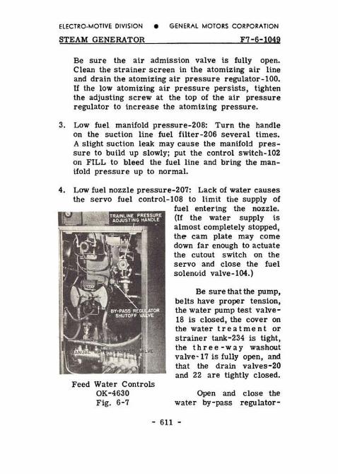
ELECTRO-MOTIVE DIVISION e GENERAL MOTORS CORPORATION
STEAM GENERATOR F7-6-1049
Be sure the air admission valve is fully open. Clean the strainer screen in the atomizing air line and drain the atomizing air pressure regulator-100. If the low atomizing air pressure persists, tighten the adjusting screw at the top of the air pressure regulator to increase the atomizing pressure.
3. Low fuel manifold pressure-208: Turn the handle on the suction line fuel filter-206 several times. A slight suction leak may cause the manifold pres-sure to build up slowly; put the control switch-102 on FILL to bleed the fuel line and bring the man-ifold pressure up to normal.
4. Low fuel nozzle pressure-207: Lack of water causes the servo fuel control-lOS to limit the supply of
Feed Water Controls OK-4630 Fig. 6-7
fuel entering the nozzle. (If the water supply is almost completely stopped, the cam plate may come down far enough to actuate the cutout switch on the servo and close the fuel solenCJid valve-104.)
Be sure that the pump, belts have proper tension, the water pump test valve-18 is closed, the cover on the water treatment or strainer tank-234 is tight, the three -way washout valve-17 is fully open, and that the drain valves-20 and 22 are tightly closed.
Open and close the water by-pass regulator-
- 611 -

ELECTRO-MOTIVE DIVISION e GENERAL MOTORS CORPORATION
F7-6-1049 STEAM GENERATOR
111 adjusting handle several times to free the regu-lator from possible sediment. If the water pressure gauge-229 still registers low, close the water by-pass regulfitor shutoff valve-19. This closes the water by-pass line and permits all of the feed water to flow to the servo-fuel control-lOB; the steam generator will start at once if the by-pass regulator is causing the trouble. Set and manually regulate the trainline steam pressure by adjusting the manual water by-pass valve-B.
High feed water temperature or leaky water line connections may cause the water pump-230 to become air or vapor bound. Violent fluctuation of the water pressure gauge needle indicates this condition. Tighten leaky water line connections and bleed the line by opening the water pump test valve-lB. Allow wate.r to flow from this valve until no air or vapor bubbles are evident in the water.
Irregular Trainline Pressure
1. Burner cycles off and on: Insufficient water delivery causes the steam generator to run in superheat; the steam temperature limit control-110 operates to protect the coils against overheating. Check the water pump output as instructed in the preceding paragraphs.
2. Safety valves blow: Shut down the steam generator. Lower the trainline pressure setting on the adjust-ing handle of the water by-pass regulator-111 and start the steam generator again. If the safety valves-107 continue to pop, close the water by-pass regulator shutoff valve-19 and manually regulate the trainline steam pressure by opening and ad-justing the manual water by-pass valve-B.
- 612 -

ELECTRO-MOTIVE DIVISION e GENERAL MOTORS CORPORATION
STEAM GENERATOR F7-6-1049
REMOTE CONTROL EQUIPMENT
The remote control panel ts located on the fire-man's side of the locomotive cab. Mounted on it are a master switch to make the panel operative, and push-button switches to operate the separator blowdown valve-12 and the remote control tratnline shutoff valve-7. Three warning lights are mounted on the panel and connected to the alarm circuit of the locomotive. The lights are marked "boiler off," "hot engine" and "low oil." A trainline steam pressure gauge is mounted on the panel.
A soot blower switch is also provided. It is to be used only when a steam generator of the CFK type is included in the installation.
The remote control trainline shutoff valve-7 can be closed from the cab; it must be opened manually, however. Depress the reset lever-7a on the trainline shutoff valve-7 to the position marked "open."
SWITCH SWITCH
Remote Control Panel Fig. 6-8
- 613 -

ELECTRO-MOTIVE DIVISION e GENERAL MOTORS CORPORATION
F7-6-1049 STEAM GENERATOR
ITEMS TO REPORT
1. Water pressure greater than 450 pounds at any time. 2. Excessive stack temperature. 3. Fluctuation of the fuel manifold pressure. 4. Frequent cycling of the burner. 5. Water flow indicator not cycling. 6. Water by-pass regulator inoperative. 7. Faulty operation of the steam generator for any
reason.
- 614 -

100. Atomizing Air Pressure Regulator 101. Atomizing Alr SWitch 102. Control Switch 103. Fuel Pressure Regulator 104. Fuel Solenoid Valve 105. Fuel Spray Head 106. Overload Reset Button, Motor 107. Safety Valves 108. Servo-Fuel Control and SWitch 109. Stack Switch 110. Steam Temperature Limit Control 111. Water By-Pass Regulator and Switch 112. Water Pressure Reller Valve
200. Atomizing Air Strainer 201. Atomizing Air Pressure Gauge 202. Blower
VALVES
Valves designated by odd numbers must be OPEN during normal operation of the steam generator. Valves designated by !!!!!. numbers must be CLOSED during normal operation or the steam generator. Normally open valves are fitted with a cross type handle, normally closed valves are fitted with the standard round handle. These des-ignations apply only to the OK series steam generators.
STEAM GENERATOR OPERATION CHART TYPES OK-4630, OK-4625, OK-4616
203. Damper 220. Spark Plugs 204. Fuel FUter (Fuel pressure Une) 221. Steam Separator 205. Fuel Filter (Servo actuating line) 222. Steam Trap (Radiation) 206. Fuel Ftlter (Suction line) 223. Steam Trap (Return water line) 207. Fuel Nozzle Pressure Gauge 224. Tratnllne Steam Pressure Gauge 208. Fuel Pressure Gauge (At fuel pressure regulator) 225. Treatment Injector Filter 209. Fuel Pump 210. Fuel Strainer 211. Fuel Tank 212. Generator Steam Pressure Gauge 213. Heat Exchanger 214. Ignitlon Transformer 215. Motor Converter 216. 011 Ftller Cap 217. RadlaUon 218. Return Water Flow Indicator 219. Return Water Strainer
The following valves must be CLOSED during normal operation of the steam generator:
2. Coil Slowdown Valve and Switch 4. Ftll-Test Valve 6. Layover Connection Shutoff Valve 8. Manual Water By-Pass Valve
10. Steam Ad miss ton Valve to Radiation {Open in cold weather)
12. Steilm Separator Blowdown Valve 14. Washout Inlet Valve 16. Washout Inlet Valve 18. Water Pump Test Valve 20. Water Suction Line Drain Valve 22. Water Treatment Tank Drain Valve
226. Treatment Injector Gauge 227. Washout Solutton Inlet 228. Washout Solution Outlet 229. Water Pressure Gauge 230. Water Pump 231. Water Strainer Manifold 232. Water Tank 233. Water Treatment Injector Pump 234. Water Treatment Tank {Strainer tank only
U injector system is used)
The following valves must be OPEN during normal operation of the steam generator:
1. Atomizing Air Shutoff Valve 3. Con Shutoff Valve 7. Remove Control Tratnllne Shutoff Valve
7a. Reset Lever 9. Return Water OuUet Valve
11. Steam Admission Valve to Tratnllne Pressure Gauge 13. Steam Admission Valve to Water By-Pass Regulator 15. Slop and Check Valve 17. Three-Way Washwt Valve 19. Water By-Pass Regulator Shutoff Valve 21. Water Supply Stop Valve
m ,... a "' 0 ~ 0 .... < m 0 < v; 6 z
• (j) m z m "' > r-;:: Q 0 "' "' () 0 "' 0 "' ~ 6 z


STEAM GENERATOR TROUBLE SHOOTING CHART I~ ~ m 0 () ..... c::: "' Symptoms Cause of Trouble Remedy til 0 t"' i:::
Panel lights do not light; Main battery switch "OPEN" Close t'l 0 ::!
bell does not ring Auxiliary generator switch "OPEN" en < (Control switch "OFF" :::c m
100 amp. boiler fuse (2) blown (distribution panel) Test and replace 0 0 Main boiler switch "ON) 0 ~
10 amp. control fuse (2) blown (boiler panel) Test and replace ~ "" 2 6 Motor does not run (control Stack switch tripped Re-set C'l z switch "FILL," bell rings) Motor overload tripped Re-set •
(l) Coil blowdown valve ''OPEN" Close .... (jl -::1 Motor runs, no strong flow Water tank empty Fill m z of water from water pump m
Valve on suction line closed (on line to treatment Open "' test valve > tank) r-
;::: Drain valve on suction line or treatment tank open Close 0 ..... Top of treatment tank not tight Re-set and tighter. 0
"' "" Treatment tank strainer clogged Clean () 0
Water in storage tank too hot Make sure steam "'! "' .., heat valve to -::1 0 I "' water tank is (l) > I ..... closed (l) 6 ~
tD z

0> ... CD
Symptoms
STEAM GENERATOR TROUBLE SHOOTING CHART (CONT'D)
Cause of Trouble Remedy
Motor runs, no spark at electrodes
Motor runs, fire does not light "Run"
Generator shuts off, bell rings
Wires from electrodes to transformer broken or grounding Terminals loose on transformer
Gap between electrodes too wide
10 amp. ignition fuse (2 on boiler panel) blown
Atomizing air valve closed
Motor not allowed to stop before turning switch to run
Electrodes not properly adjusted
Nozzle not properly adjusted
Stack switch tripped
Repair
Tighten
Reduce gap (should be 3/16 ")
Test and replace
Open
Turn ''fill" briefly, then to "off. " After motor has stopped and servo control is all the way down, turn to "Run" Adjust. Report to maintenance.
Adjust. Report to maintenance.
Reset stack switch, refill coils, start steam generator, and set water by -pass regulator at slightly lower pressure. Report to maintenance.
"l m ,.... -'1 m
I () 0> .... I "' 0> 0 "'" ~ co 0 .... < m
0 < Vi 6 z
• (j\ m z m "' >-3 > r-
el ;::: c: 0 .... tp 0 t"' "' ttl "' () en 0 ::z: "' 0
..., 0 0 "' >-3 >
2 _, 6
0 z

a> ... <0
Symptoms
STEAM GENERATOR TROUBLE SHOOTING CHART (CONT'D) Cause of Trouble Remedy
Generator shuts off,
Generator runs, dome gets hot
Generator runs but no water returns through water flow indicator
Generator runs but trainline pressure cannot be controlled by water by-pass regulator
Motor overload relay trips, shutting down generator
Lack of air, dirty coils
Valve in return line from separator closed
Return water strainer clogged
Steam too dry
Steam admission valve closed
Water admission valve closed
Defective water by-pass regulator
Reset overload relay, refill coils and start steam gener-ator. Report to maintenance. Set water by-pass regulator back 10 to 15 lbs. Report to maintenance.
Open
Clean
Report to maintenance
Open
Open
Close water shutoff valve to water by-pass regulator, use manual by-pass valve to con-trol pressure. Report to maintenance.
...,:) ~ ::tJ m 0 Q c "' Ill c;:> t" s: t'l 0 (Jl ::I: 0 Q 2 0
--< < m 0 ~ Vl
6 z
• (j) m z m
"' > ,.... s: 0 --< 0 "' Vl
() 0
">j ~ -.1 0 I "' a> > I --<
a> -"'" 0 <0 z

ELECTRO-MOTIVE DIVISION e GENERAL MOTORS CORPORATION
F7- 6A-1149 STEAM GENERATOR
SECTION 6-A
STEAM GENERATOR ELESCO TYPE
INTRODUCTION
The instructions contained in this section are for the guidance of personnel engaged in the operation of Elesco steam generators. A general description of the steam generator is given, the operating technique is outlined and a trouble shooting section is provided for the operator.
The numbers in parentheses are identified in the numerical listing at the end of the section. Some of these items are illustrated in this section, however some of the reference numbers not illustrated will be found on the schematic chart mounted on the locomo-tive close to the steam generator.
DESCRIPTION
The Elesco steam generators have a rated capacity of 2300 and 3000 lbs. of water evaporation per hour. Operation is completely automatic after the steam gen-erator is started, and full operating steam pressure is reached within a few minutes. The steam generator operates on the forced recirculation principle and. therefore, is not dependent upon natural circulation. A small hot water circulating pump, close-coupled to an electric motor, forces the hot water which is con-tained in the system at steam temperature through the elements of the generator. While the generator is in operation, the quantity of water circulated is constant, regardless of steam output. At maximum capacity, the quantity of water circulated is approximately ten times
- 600A -

~---- 32
33 .it:==-4-- _;... __ 34
~!!!!:-!-- 35
37
Fig. 6-1 - Steam Generator - Top And Side Views
- 601A -

ElfCTRO·MOTIVE DIVISION e GENER!\l MOTORS CORPOR!\TION
F7-6A-1149
58 89 V1 68
Fig. 6-2 - Steam Generator
STEAM GENERATOR
84 98
$0
17
L--~:--- 16
~-~"'9::::0,.- 53
55 20
23
25
Front View
the amount of steam produced. The forced recirculation principle assures efficient heat transfer and eliminates scale formation almost entirely.
The steam generator consists of a radiant or combustion chamber section and a convection section. The heating surface of the radiant section consists of three elements forming the envelope of the combu:;tion chamber. Each element is connected to the inlet and
- 602A -

ELECTRO-MOTIVE DIVISION e GENERAL MOTORS CORPORATION
STEAM GENERATOR F7-6A-1149
outlet headers. The convection section consists of five elements, each of which is also connected to the inlet and outlet headers. Each of the eight elements is equipped with an orifice at the inlet end to insure proper distribution of the circulated water.
The electric motor which drives the circulating pump also drives the fuel oil pump and blower.
The feedwater pump is of the reciprocating type and is steam-operated. The steam flow to the pump is controlled by the feedwater regulator, which is actuated by a float located in the steam separator. A rise in water level reduces the feedwater regulator valve opening and retards the speed of the pump, and a reduction in water level effects the reverse.
The burner is designed to utilize light grades of fuel oil such as Diesel oil. The burner head has three mechanical atomizing burner nozzles one of which is referred to as the "small burner" and the other two combined as the "large burner." Electric ignition is employed and the spark is only provided during a five second ignition period. Only the small burner is ignited when lighting up after which the larger burner is later ignited by the flame of small burner.
The fuel oil supply to small burner atomizing nozzle is not regulated. The fuel oil pumped to the larger burner mechanical atomizing nozzles is con-trolled by an oil regulating valve actuated by steam pressure. When the steam pressure is low, fuel oil flow to the larger burner will be maximum, and an increase in steam pressure above normal will result in a reduction of fuel oil flow. Proper mixture of air and fuel oil is automatically maintained at all rates of firing, thus high combustion efficiency is assured at all load settings.
- 603A -

ELECTRO-MOTIVE DIVISION • GENERAL MOTORS CORPORATION
F7-6A-1149 STEAM GENERATOR
THE CONTROL FOR THE WATER AND THE CONTROL FOR THE FUEL OIL ACT INDEPENDENTLY OF EACH OTHER AND THUS DO NOT HAVE TO BE COORDINATED.
The steam supply to the trainline is controlled 'by a reducing valve which can be adjusted to give the desired trainline pressure. A manual by-pass valve is incorporated in the reducing valve body, the handle of which is located on the opposite end of the reducing valve. This by-pass valve can be used to feed the trainline in case proper regulation cannot be obtained with the reducing valve. A trainline shut-off solenoid valve and an under-pressure valve are located in the reducing valve pressure control line to open or close the reducing valve. The trainline shut-off solenoid valve must be manually latched open to permit the reducing valve to open. It can be tripped by remote control from the cab, thereby closing the reducing valve and shutting off the steam supply to the trainline.
Fig. 6-3 - Remote Control Panel
- 604A -

ELECTRO-MOTIVE DIVISION e GENERAL MOTORS CORPORATION
STEAM GENERATOR F7-6A-1149
- 605A -

ELECTRO-MOTIVE DIVISION e GENERAL MOTORS CORPORATION
F7-6A-1149 STEAM GENERATOR
Before Starting Steam Generator
1. Auxiliary generator on locomotive should be running and main air reservoir should have at least 60 lbs. pressure.
2. Check position of all valves. Valves with cross han-dles should be fully opened. Valves with round han-dles should be closed, excepting water glass valves (2 and 6).
3. Turn handles (7) on fuel oil strainer one full turn. 4. Close main switch by moving handle (1) to the "ON"
position.
Starting Steam Generator
1. 1f no water shows in the glass, run feedwater pump (10) on air as follows: a. Close pump steam valve (23). b. Open pump air valve (9). c. Open steam separator air vent cock (3), while
filling. 2. When water reaches top of water glass, place control
switch (12), in starting position. Push "START" but-ton (14), and motor will run.
3. Continue to operate feedwater pump on air until water remains in water glass, then shut pump air valve (9) and open pump steam valve (23).
4. Close steam separator air vent cock (3). 5. Push and release differential pressure valve water
line snubber (65) two or three times to insure full opening in pressure line to differential pressure valve.
6. Place control switch (12), in running position. Steam generator will fire.
7. As steam generator comes up to pressure, water will tend to rise, use manual blow-down valve (25) to keep about 1/2 glass of water.
- 606A -

ELECTRO-MOTIVE DIVISION e GENERAL MOTORS CORPORATION
STEAM GENERATOR F7-6A-1149
To Feed Steam To Train Line
Steam generator pressure should be 275 lbs. shown on pressure gauge (16) red hand before proceeding.
1. Set lever of steam flow control valve (22) in posi-tion 2.
2. Open remote control steam shut-off solenoid valve (5) by pulling lever down to latched position.
3. Slowly open main steam line shut-off valve (18) to full open position.
4. If required, use manual blow-down valve (25) to keep about 1 j2 glass of water.
5. Loosen wing lock nut on stem of steam pressure reducing valve (21), and adjust this valve to give the desired reducing valve setting. After reducing valve to set, tighten wing lock nut.
6. For high trainline steam demands, during cold weather, move lever of steam flow control valve (22) very slowly to position 4.
7. When trainline is fully charged, trainline pressure will be about reducing valve pressure. These pres-sures show on steam gauge (17).
Paralleling Steam Generators
1. Set steam flow control valve levers (22) in same position.
2. Adjust reducing valve (21) to have about same pres-sures, white hand on steam pressure gauge (17) within 5 to 10 lbs.
Running Attention
1. Operate remote control solenoid blow-down valve (11) about 5 seconds every 1 j2 hour by means of separator blow-down switch on remote control panel in locomotive cab.
- 607A -

ELECTRO-MOTIVE DIVISION e GENERAL MOTORS CORPORATION
F7-6A-1149 STEAM GENERATOR
To Shut Down Steam Generator
1. Close steam shut-off valve (18), and open manual blow-down valve (25), slowly and blow for 5 seconds.
2. Push "STOP" button (13), the motor will continue to run but at a reduced speed for cool-down period.
3. When steam pressure has dropped to about 50 lbs. motor will automatically stop. After motor has stopped, move main switch handle (1) to "OFF" position.
To Shut Down Steam Generator Enroute During Cold Weather
1. Close steam line shut-off valve (18). 2. Push "STOP" button (13). 3. Open manual blow-down valve (25) and circulating
pump drain valve (8) wide to thoroughly blow-down generator. After generator is blown down leave these valves cracked open.
4. Open oil regulating valve drain (4), differential pres-sure valve steam line drain (19), differential pres-sure valve water line drain (20), and feedwater pump steam line drain (24). Close water suction line stop valve (28) and open feed pump suction line drain valve (27).
5. Open steam generator heater valve (15). This con-nects steam generator to trainline, allowing steam from trainline to enter to prevent freezing.
6. Move main switch handle (1) to "OFF" position.
- 608A -

m 0 co >
TROUBLE SHOOTING
NORMAL TROUBLE ACTION
1. When main switch closed ---- -
a. Pressure gauge If one of these lamps does Check for burned out lamp. lamp, water glass not light. lamp, and electric Check for blown main line eye indicating lamp If none of these lamps fuses or tripped line circuit all light. light. breaker if used. Check for
blown fuses in motor control cabinet.
- ·-j---- ------b. Alarm bell should If alarm bell rings. Push "Stop" button in. Check
not ring. control switch -it should be --·-
in "Starting" position. r- -- -- -- ---2. After pushing "Start"
button with control switch in "Starting" position.
----- -- ------------ -a. "Stop" button is auto- If "Stop" button does not Check "Start" and "Stop"
matically released. release. buttons for defects. --'----------------~----· --· --- --·
til m o-'3 r
m 1:>:1 ()
> --1
"' ==
0
0 ~ 0
1:>:1 --1 z < 1:>:1 m
~ ~ <
o-'3 Vi
@ 6 z
• (j) m z m
"' > r
;:: 0 --1 0 "' "'
"fj ()
-.3 0 I "' m " > 0
"' I > .... _, ..... 6 "" co z

I~ m
TROUBLE SHOOTING ~
m I n
(j) .... I~ "' NORMAL TROUBLE I ACTION 0 .... ~ .... 0
(2. Continued) I .... .... co < I m b. Motor starts and If motor does not start. Check "Reset" of motor 0
comes up to speed, overload relay in motor con- ~
"' driving circulating trol cabinet. Reset if neces- 6 pump, fuel oil pump, sary by pushing reset button z
and blower. down. Check main line fuses I • (j) (or if circuit breaker is used, .... reset it if found tripped.) (j\ 0 > m
Check for blown fuses in z m
motor cabinet. "' Ul ~ -----r---- - ---- ~ ;::: (':
c. "Start" indicating If "Start" indicating lamp Check for burned out lamp. > 0 .... ==
0 I•mp light•. --~~ not light •nd moto' "' 0 "' 1s runnmg. t>:l n
0 z "' t>:l " d. Alarm bell should not I
If alarm bell rings. ! Check control switch. It ~ 0 "' > ring. should be in "Starting "posi- ~ ....
tion. 0 6 ::tl z

a> .... .... >
NORMAL 3. Steam Generator
Running. a. Pressure gauge,
white hand, circulat-ing pump pressure should be 30 to 40 lbs. greater than red hand. (The 30 to 40 lbs. difference in these pressures is called "Differential Pressure.") It shows steam generator has proper water circu-lation.
b. Fuel oil pressure gauge, red hand, p u m p pressure should be 250 lbs.
TROUBLE SHOOTING -~~-·-
TROUBLE ACTION ---------
If there is no differential Check for proper amount of pressure or pressure is water in steam generator low or unsteady. about 1/2 glass and add water
if necessary. Push plunger on snubber in differential pressure valve water line to clean snubber. Check circu-lating pump discharge line strainer - it may require cleaning.
If fuel oil pump pressure is low or no pressure.
Check for oil in pump suction line by inspecting flow in sight glass. Turn handle on fuel oil pump suction line
C/l m IJ-3 ~ tr:l () > ;; El:: 9 Cl ~ tr:l g z < tr:l m
s; ~ o-3 ~ 0 0 ::0 z
• (j) z m
"' > r-
;:: 0 -< 0 "' V>
() 0 "' ., 0 "' > --< 6 z
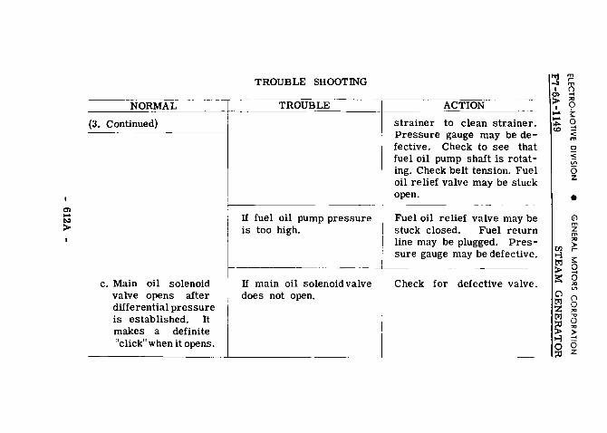
0) .... ~
>
NORMAL
(3. Continued)
c. Main oil solenoid valve opens after differential pressure is established. It makes a definite "click" when it opens.
TROUBLE SHOOTING
TROUBLE
If fuel oil pump pressure is too high.
If m~n ~1 so~n~dva~e does not open.
ACTION
strainer to clean strainer. Pressure gauge may be de-fective. Check to see that fuel oil pump shaft is rotat-ing. Check belt tension. Fuel oil relief valve may be stuck open.
Fuel oil relief valve may be stuck closed. Fuel return line may be plugged. Pres-sure gauge may be defective.
Check for defective valve.
~ ~ -:1 m I ()
0> .... > 0 I • .... ;:::
.... 0 "" .... co < m c < v; 6 z
• (j) m z m
"' til )> t-i r t<:l ;:: > 0 := 0
"' Cl VI
t<:l () z 0 t<:l ::: ~ ~ t-i ~ 0 6 ::tl z

en .... t.o >
NORMAL ~· 4. Control switch is placed
in "Running" position to make steam genera-tor fire.
a. ''Burner On" lamp lights.
TROUBLE SHOOTING
~TROUB~-f ~-ACTION If "Burner On" lamp does I Check for burned out lamp. not light and steam genera-tor fires. t
----- --- - -- -- --~ ---
b. Small burner oil so-lenoid valve opens. This will be indicated by fuel oil pressure gauge, red hand dropping slightly. Ignition converter
If "Burner On" lamp does Check Items under "Action" not light and alarm bell 1 3-a. rings.
If steam generator does r-not fire within about 5 seconds, shut-down will occur and alarm bell will ring.
Restart steam generator, check fuel oil pump pressure and when control switch is placed in "Running'' position note slight drop in fuel oil pump pressure which indi-cates that small burner oil
til m >-3 ~ 1:':1 () > ;:l ;s:: 9 0 !:: 1:':1 g z < 1:':1 m
~ ~ >-3 ~ 0 0 ::l:l z
• (j) m z m
"' > r-;:: 0 .... 0 "' V>
"J 8 -.J "' I -, Cf> 0 > "' I > .... = .... 0 ~ z

a> .... "'" >
NORMAL
(4. Continued)
runsfor about 5 sec-onds providing spark, after which it cuts out. As soon as fire is established electric eye indicating lamp goes out.
TROUBLE SHOOTING
TROUBLE
If no spark or improper spark.
ACTION
solenoid valve opens. If no drop in pressure, check for defective small burner oil solenoid valve or main oil solenoid valve. Check small burner nozzle for plugging. Check through burner peep hole for proper spark. Check air damper and rigging to see that it is in low position.
Check electric wiring between ignition transformer and electrodes. Check for dirty or defective electrodes. (Gap between electrodes should be 3/16".) Check to see if ignition converter is running.
m "'l ,.--'1 m I ~
a> "' > 0 I • .... s::
.... 0 "'" .... <0 < m ~ < iii 6 z
• (j) m z m
"' en > o-3 r
t<:l s:: > 0 a:: 0 "' C'l V'
t<:l () z 0 t<:l ~ ~ ~ o-3 ~ 0 6 ::0 z

0> .... CJ1 >
TROUBLE SHOOTING
NORMAL
(4. Continued) __ i ---=TROUBLE ~---:-::-1
If steam generator fires for about 5 seconds and electric eye indicating light remains on and then a shut-down occurs with both "Start" and "Burner
: On" indicating lights going
+out and alarm bell rings. --"- - "--"---"- ----
c. Steam gen~rator op-erates on s m a II burner until steam pressure, red hand on pressure gauge, 1s about 30 lbs. The large burner so-lenoid v a 1 v e then opens and large burn e r comes on, this is indicated by
ACTION ---- "_"_" ____ _ With steam generator shut down, clean electric eye shutter sight glasses. Check electric eye tubes.
(/.1 '"'l 1:':1 > rs:: 0 1:':1 z 1:':1
~ '"'l 0 ::ll
m .--m () --< "' 0 t 0 ::! < m Cl
< v; 6 z
• (j) m z m "' > .--;::: 0 -I 0 "' "' () 0 "' -., 0 "' > --< 6 z

0> .... ~
NORMAL
(4. Continued)
pressure showing on white hand of fuel oil gauge. Cijl pressure of large burner startstofalloff when steam pressure reaches 260 lbs. and oil pressure drops t9 zero when steam pressure reaches 270 lbs. When steam pre s s u r e reaches 290 lbs. small burner automatically shuts down and then "Burn-er On " indicating light goes out.
TROUBLE SHOOfiNG
TROUBLE
If large burner oil pres-sure, white hand of fuel oil gauge, does not start to decrease at about 260 lbs. steam pressure and large burner remains on until "Burner On" indicat-ing lamp goes out.
ACTION
Check for defective oil regu-lating valve bellows. This is indicated by steam leak at lower part of assembly.
l'lj \!! -'1 m I ~
0> "' > 0 I ' .... ;::
.... 0 ""' ..... co < m 0 ~ Vl
6 z
• Gl m z m
"' rn > '"i r t"l ;::: > 0
== 0 "' 0 Vl
t"l () z 0 t"l ~ ~ ~ >-i· ~ 0 -::0 ~

a> ..... -'1 >
NORMAL
5. Steam generator oper-atingwith trainline shut-off valve closed.
a. Steam generator fire is automatically cut out when steam pres-sure reaches 290 lbs. When steam pressure drops to 275 lbs. it refires. Small burner going on and off at short intervals is called "Cycling. "
TROUBLE SHOOTING
TROUBLE
H steam generator shuts down when cycling; alarm bell rings with both the "Start" and "Burner On" indicating lights out; and motor running at reduced speed. H alarm bell rings with "Start" indicating light on and "Burner On" indicating light out.
ACTION
Place control switch in "Starting" position - this
will cut out alarm bell. Re-start steam generator. Place control switch in "Running" position. Also check items under "Action" 4-b.
Check items under "Action" 3-a. Check feedwater pump steam valve for full open. Check water glass on steam separator for indication that water in steam separator may be foaming- if so, give good blow-down using manual blow-down valve.
tiJ m ~ ~ t>l () > ;ci ~ 0
0 § t>l :::! z < t>l m
~ ~ ~ ~ 0 0 ::0 z
• (j) m z m
"' > r
;::: 0 -< 0 "' V>
>'1j () -'1 0 I "' a> ., > 0 I "' = ~ "'" 0 co z

Cl> .... f:;
NORMAL (5. Continued) ---- -- - - ·-· ---
6. Steam generator feed-ing steam to trainline.
a. With low steam de-mand steam genera-tor may cycle as in "5. II With normal steam demand, both the small and large burners will be on. Large burner pres-sure, white hand on fuel oil gauge, is con-trolled by oil regulat-ing valve and it varies with steam demand.
TROUBLE SHOOTrnG
TROUBLE
If smoke shows at stack when refiring and then stack clears.
---
If steam generator stops firing; alarm bell rings with "S t a r t "indicating light on; and "Burner On" indicating light out.
ACTION
Check small burner air damp-er and electrodes. Burner is not igniting as quickly as it should.
Check differential pressure water in glass, water storag tank, feedwater pump and it piping. Checkfeedwater pum steam valve for full oper Check action feedwater pumi may be sucking air throug leaky cover on water treat ment tank. Check item under "Action" 5-a. Chec treatment tank drain valvE Should be closed.
p
h
s k
'x:l m ,--'1 m I () :: -I
"' I 9 ... !:: .... ~ 0 co :::!
< m 0 < Vi 6 z
• (j) m z m
"' ~ ~ t>:l !:: > 0 5!::
-I 0 "' 0 VI
t>:l ()
z 0 t>:l "' ..., ~
0 "'
o-,3 > -I
0 6 :.l z

Cl) ..... ~
NORMAL
(6. Continued)
'
TROUBLE SHOOTING
TROUBLE
If steam generator shuts down; alarm bell rings; "Start" and "Burner On" indicating lights out; and motor running at reduced speed.
If steam generator shuts down, alarm bell rings, both indicating lights out, motor shuts down.
If smoke shows at stack with large burner on.
-
ACTION
til m ~
r-m t"l ()
> .... "' a':: 0 ~
Checkforfueloil pump pres-sure. With steam generator off, clean electric eye shutter sight glasses. Also check items "Action" 4-b.
0 0 t"l .... z < t"l
m
~ Q <
~ Vi
~ iS z
• Check for blown main line fuses. Also check items under "Action" 2-b.
(j) m z m "' > r-~
Check action of air damper and rigging. Check blower
0 0 "' "' belt drive. "'l ()
-J 0 I "' Cl) ..., > 0 I "' ..... >
..... ::! ~ 0 <Q z

ELECTRO-MOTIVE DIVISION • GENERAL MOTORS CORPORATION
F7-6A-1149 STEAM GENERATOR
Ref. No.
1. 2. 3. 4. 5.
6. 7.
8. 9.
10. 11. 12. 13. 14. 15. 16. 17. 18. 19.
Name Of Part
Main Switch. . . . . . . . . . Water Glass Upper Shut-off Valve . Steam Separator Air Vent Cock .. Fuel Oil Regulating Valve Drain Cock . Remote Control Steam Line Shut-off
Solenoid Valve .......... . Water Glass Lower Shut-off Valve . Fuel Oil Pump Suction Line Strainer
Handle ............ . Circulating Pump Drain Valve Feedwater Pump Air Valve .. Feedwater Pump . . . . . . . . Remote Control Blow-Down Solenoid Valve Control Switch "Stop" Button . . . . . . . . "Start " Button . . . . . . . . Steam Generator Heater Valve Steam Generator Pressure Gauge . Steam Line Pressure Gauge. . . . Steam Line Shut-off Valve ..... Differential Pressure Valve Steam
Line Drain ............ . 20. Differential Pressure Valve Water
21. 22. 23. 24. 25. 26. 27. 28. 29. 30. 31.
Line Drain .......... . Steam Pressure Reducing Valve Steam Flow Control Valve .... Feedwater Pump Steam Valve .. Feedwater Pump Steam Line Drain Manual Blow-Down Valve ..... Washout Valve . . . . . . . . . . . Feedwater Pump Suction Line Drain Valve Feedwater Pump Suction Line Valve Inlet Header Pipe Plug . . . . . Manual By-Pass ........ . Oil Burner Control Junction Box
- 620A -
Refer to Figures
6-5 6-1, 6-5 6-1, 6-5
6-5
6-5 6-1, 6-5
6-1, 6-5 6-2, 6-5 6-2, 6-5 6-2, 6-5 6-2, 6-5
6-5 6-5 6-5 6-5
6-2, 6-5 6-2, 6-5
6-5
6-5
6-2, 6-5 6-5 6-5
6-2, 6-5 6-5
6-2, 6-5 6-2, 6-5
6-5 6-5 6-5 6-5 6-1
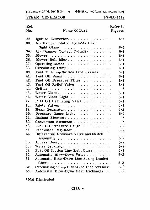
ELECTRO-MOTIVE DIVISION e GENERAL MOTORS CORPORATION
STEAM GENERATOR F7-6A-1149
Ref. Refer to No. Name Of Part Figures
32. Ignition Converter. 6-1 33. Air Damper Control Cylinder Drain
Sight Glass 6-1 34. Air Damper Control Cylinder 6-1 35. Blower. . . 6-1 36. Blower Belt Idler. 6-1 37. Operating Motor 6-1 38. Circulating Pump . 6-1 39. Fuel Oil Pump Suction Line Strainer . 6-1 41. Fuel Oil Pump 6-1 42. Fuel Oil Pressure Filter 6-1 43. Fuel Oil Relief Valve 6-1 44. Orifices . . * 45. Water Glass. . . . . 6-1 46. Water Glass Light 6-1 47. Fuel Oil Regulating Valve 6-1 48. Safety Valves 6-1 49. Steam Separator. 6-2 50. Pressure Gauge Light 6-2 51. Radiant Elements . * 52. Convection Elements * 53. Fuel Oil Pressure Gauge 6-2 54. Feedwater Regulator . 6-2 55. Differential Pressure Valve and Switch
Assembly 6-2 56. Access Door. 6-2 58. Water Separator. 6-2 59. Fuel Oil Suction Line Sight Glass. 6-1 60. Automatic Blow-Down Valve . 6-2 61. Automatic Blow-Down Line Spring Loaded
Check 6-2 62. Circulating Pump Discharge Line Strainer. 6-2 63. Automatic Blow-Down Heat Exchanger 6-2
*Not Illustrated
- 621A -

ELECTRO-MOTIVE DIVISION e GENERAL MOTORS CORPORATION
F7·6A·1149 STEAM GENERATOR
Ref. No.
64.
65.
66. 67.
68. 69. 70. 71. 72. 73. 74. 75. 76. 77. 78. 79. 80. 81. 82. 83. 84.
85. 86. 88. 89. 90. 91. 92. 93.
Name Of Part
Circulating Pump Discharge Line Check Valve ................. .
Differential Pressure Valve Water Line
Refer to Figures
6-2
Snubber ................ . Steam Generator Control Cabinet . . . . Feedwater Pump Discharge Line Check
• 6-2, 6-5 6-2
Valve ............... . Electric Eye Flame Failure Control Fuel Oil Solenoid Valve Manifold Main Oil Solenoid Valve . . . . . . Large Burner Oil Solenoid Valve Small Burner Oil Solenoid Valve. Soot Remover Air Gates . . . . . Cover for Soot Remover Container Ignition Transformer . • . . . . Ignition Electrodes Lead Wires Small Burner Flexible Oil Hose Large Burner Flexible Oil Hose Ignition Electrodes . . Burner Head . . . . . Oil Burner Peep Hole Burner Wind Box . . . Inlet Header . . . . . . . . . . . . . . Differential Pressure Valve Steam Line
Snubber ...... . Feedwater Heater . . . . . . . . . Smoke Stack Opening . . . . . . . Fuel Oil Suction Line Check Valve Outlet Header . . . . . . . . . . . Sludge Settling Chamber ..... Water and Steam Inlet to Steam Separator Water Separator Primary Chamber . Steam Separator Secondary Chamber .
6-2 6-2 6-1 6-1 6-1 6-1 6-1 6-1 6-1 6-1 6-1 6-1 6-1 6-1 6-1 6-1 6-1
6-2 6-1 6-1 6-1 6-2
* * * *
*Not illustrated
- 622A -

ELECTRO-MOTIVE DIVISION e GENERAL MOTORS CORPORATION
STEAM GENERATOR F7-6A-1149
Ref. Refer to No. Name Of Part Figures
94. Feedwater Pump Exhaust Vent Pipe . 6-1 95. Sludge Settling Chamber Inlet. .. * 96. Sludge Settling Chamber Outlet . * 97. Sludge Settling Chamber Metering
Choke. 6-2 98. Pressure Gauge Steam Line Shut-off
Valve. 6-2 99. Feedwater Pump Steam Heat Exchanger. *
100. Circulating Pump Stuffing Box Cooling Water Strainer . 6-2
*Not illustrated
- 623A -

