diaphragm design
DESCRIPTION
Diaphragm DesignTRANSCRIPT
11
2003 IBC Chapter 162003 IBC Chapter 16
Seismic DesignSeismic DesignDiaphragmsDiaphragms
22
SCOPESCOPE
�� Diaphragm DesignDiaphragm Design•• Diaphragm System ReviewDiaphragm System Review•• Load CombinationsLoad Combinations•• Vertical Distribution of Horizontal LoadsVertical Distribution of Horizontal Loads•• Diaphragm LoadsDiaphragm Loads•• Diaphragm DesignDiaphragm Design•• Openings in DiaphragmsOpenings in Diaphragms
�� Wall AnchorageWall Anchorage•• Wall SupportWall Support•• SubSub--diaphragmsdiaphragms
33
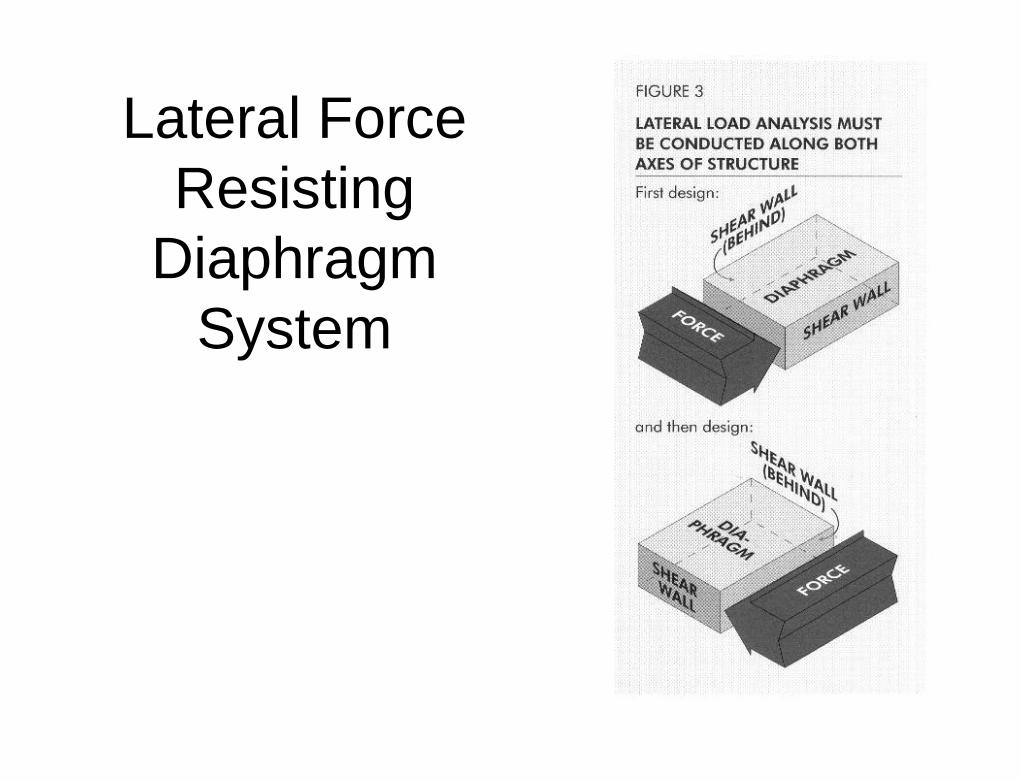
Lateral Force Lateral Force Resisting Resisting
Diaphragm Diaphragm SystemSystem
44
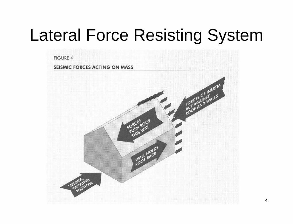
Lateral Force Resisting SystemLateral Force Resisting System
55
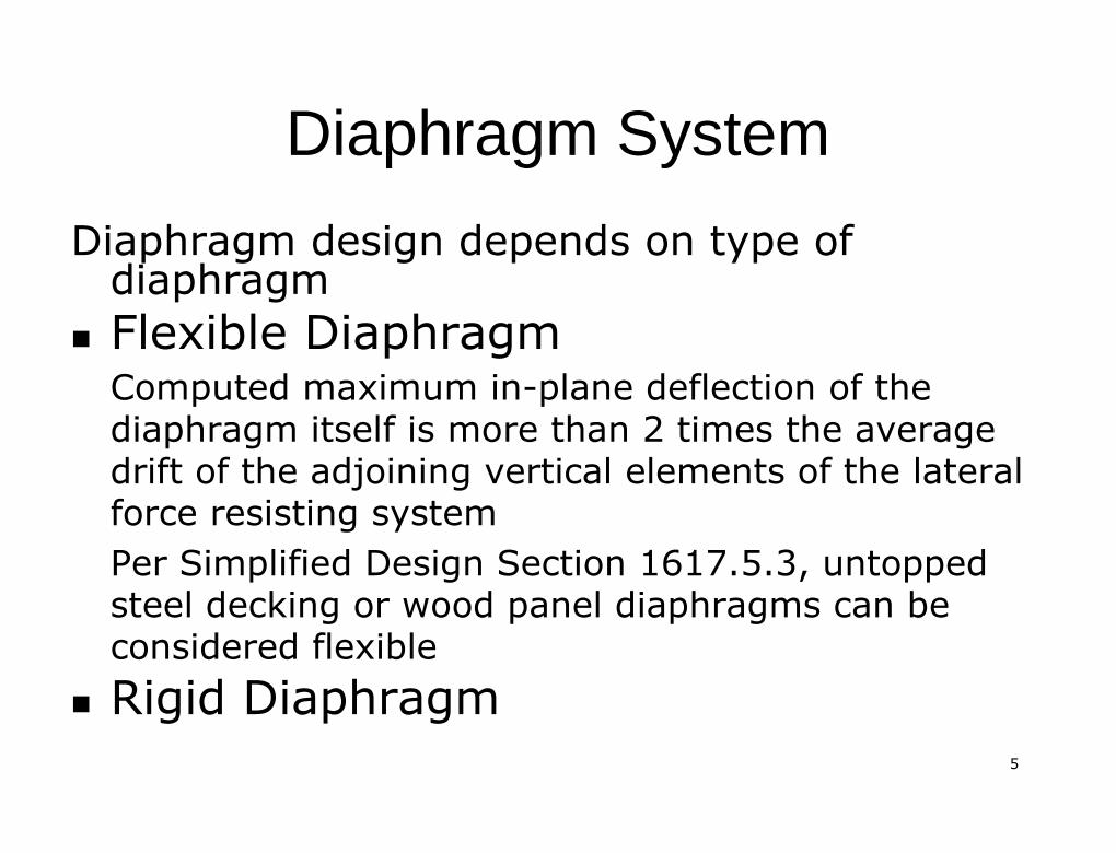
Diaphragm SystemDiaphragm System
Diaphragm design depends on type ofDiaphragm design depends on type ofdiaphragmdiaphragm�� Flexible DiaphragmFlexible Diaphragm
Computed maximum inComputed maximum in--plane deflection of theplane deflection of thediaphragm itself is more than 2 times the averagediaphragm itself is more than 2 times the averagedrift of the adjoining vertical elements of the lateraldrift of the adjoining vertical elements of the lateralforce resisting systemforce resisting systemPer Simplified Design Section 1617.5.3,Per Simplified Design Section 1617.5.3, untoppeduntoppedsteel decking or wood panel diaphragms can besteel decking or wood panel diaphragms can beconsidered flexibleconsidered flexible
�� Rigid DiaphragmRigid Diaphragm
66
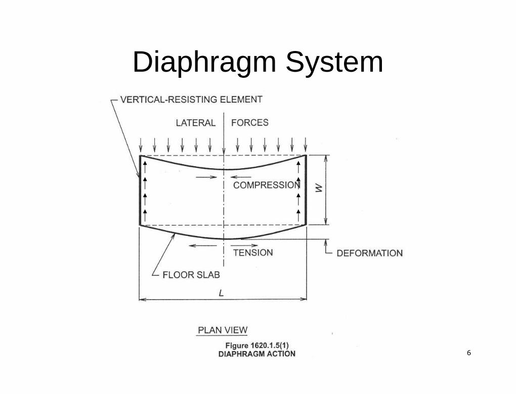
Diaphragm SystemDiaphragm System
77
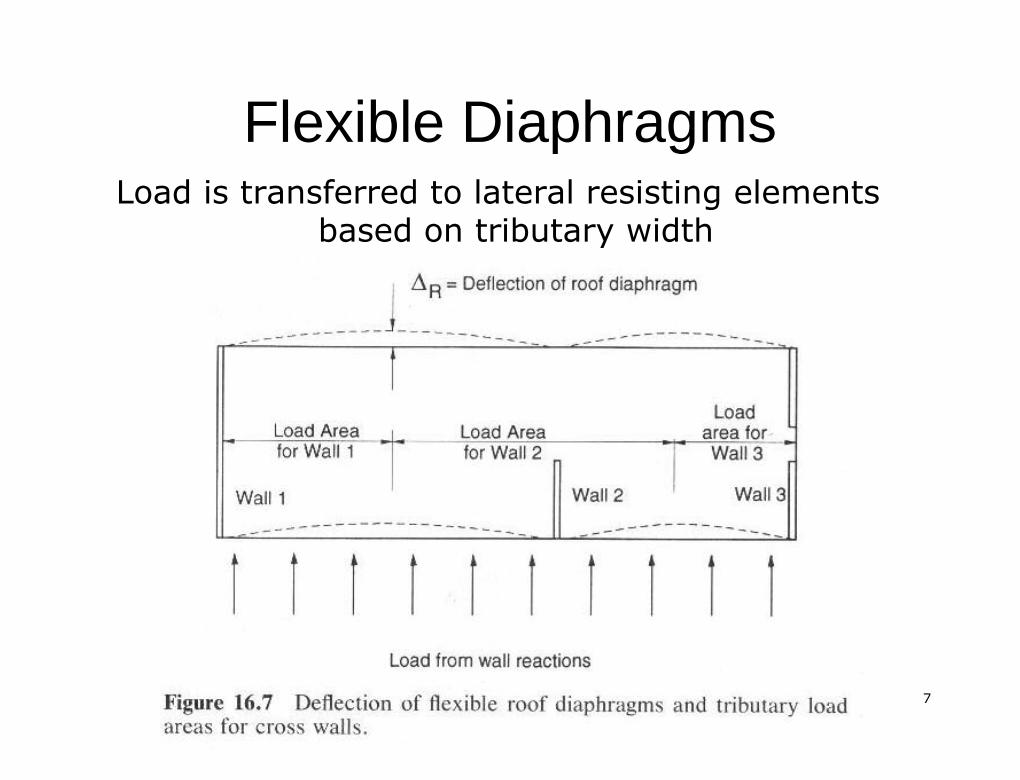
Flexible DiaphragmsFlexible DiaphragmsLoad is transferred to lateral resisting elementsLoad is transferred to lateral resisting elements
based on tributary widthbased on tributary width
88
Flexible DiaphragmsFlexible Diaphragms
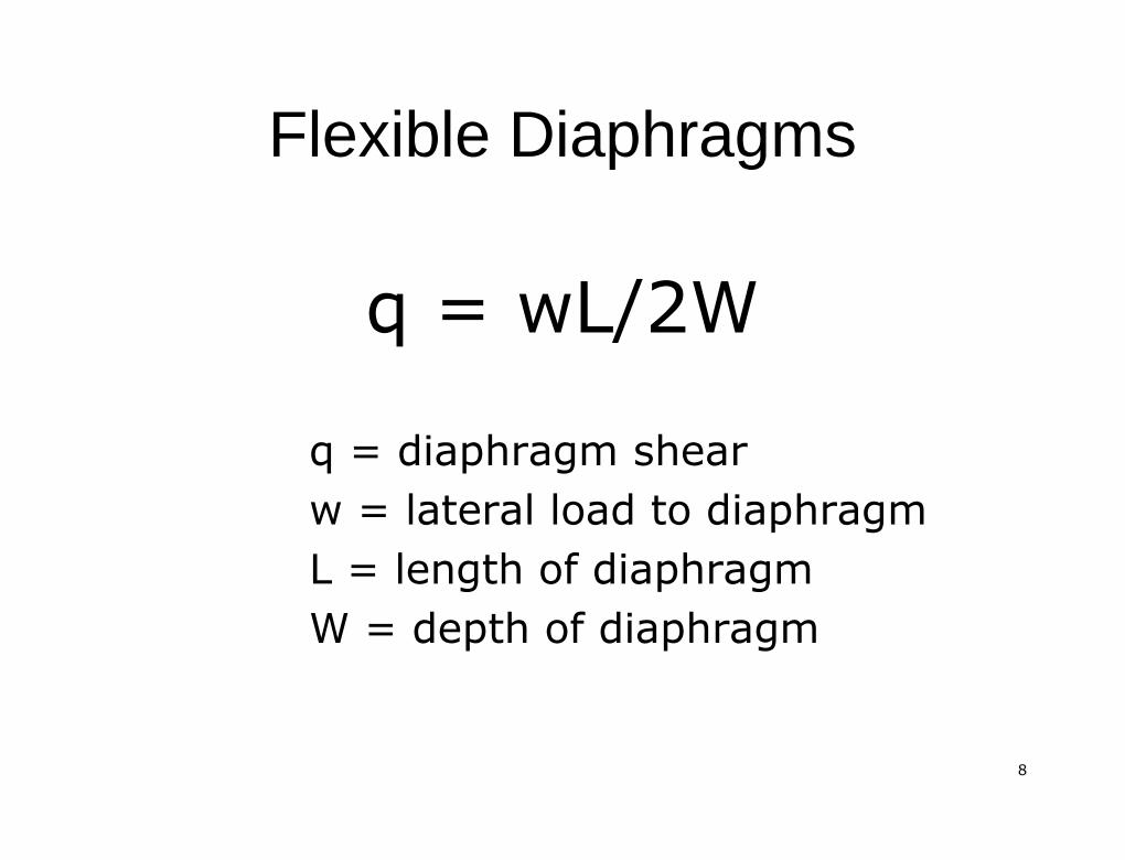
q = wL/2Wq = wL/2Wq = diaphragm shearq = diaphragm shearw = lateral load to diaphragmw = lateral load to diaphragmL = length of diaphragmL = length of diaphragmW = depth of diaphragmW = depth of diaphragm
99
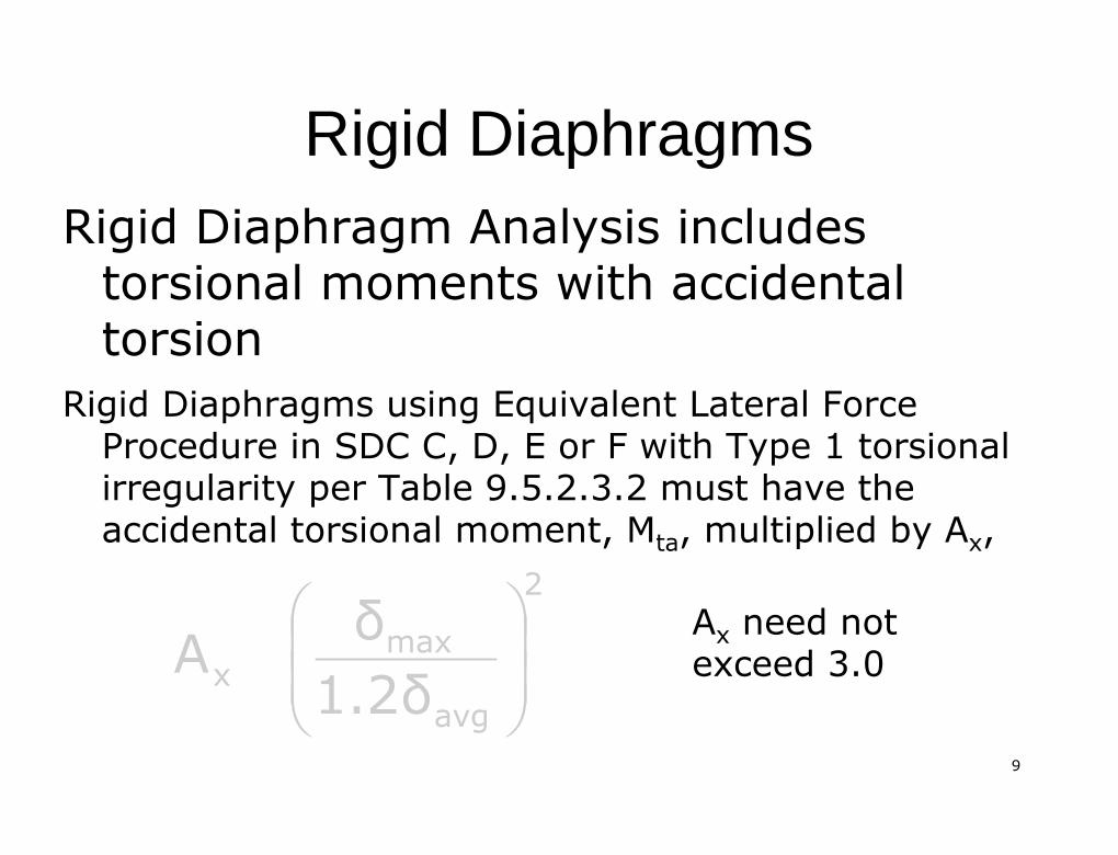
Rigid DiaphragmsRigid DiaphragmsRigid Diaphragm Analysis includesRigid Diaphragm Analysis includes
torsionaltorsional moments with accidentalmoments with accidentaltorsiontorsion
Rigid Diaphragms using Equivalent Lateral ForceRigid Diaphragms using Equivalent Lateral ForceProcedure in SDC C, D, E or F with Type 1Procedure in SDC C, D, E or F with Type 1 torsionaltorsionalirregularity per Table 9.5.2.3.2 must have theirregularity per Table 9.5.2.3.2 must have theaccidentalaccidental torsionaltorsional moment,moment, MMtata, multiplied by A, multiplied by Axx,,
AAxx need notneed notexceed 3.0exceed 3.0
2
avgmax
x 1.2δδA
1010
Rigid DiaphragmsRigid Diaphragms
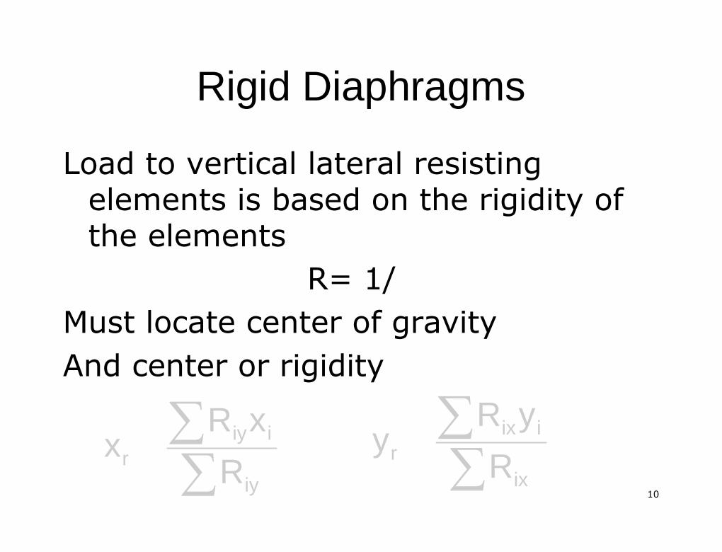
Load to vertical lateral resistingLoad to vertical lateral resistingelements is based on the rigidity ofelements is based on the rigidity ofthe elementsthe elements
R= 1/R= 1/Must locate center of gravityMust locate center of gravityAnd center or rigidityAnd center or rigidity
∑∑
iy
iiyr R
xRx ∑
∑ix
iixr R
yRy
1111
Rigid DiaphragmsRigid Diaphragms
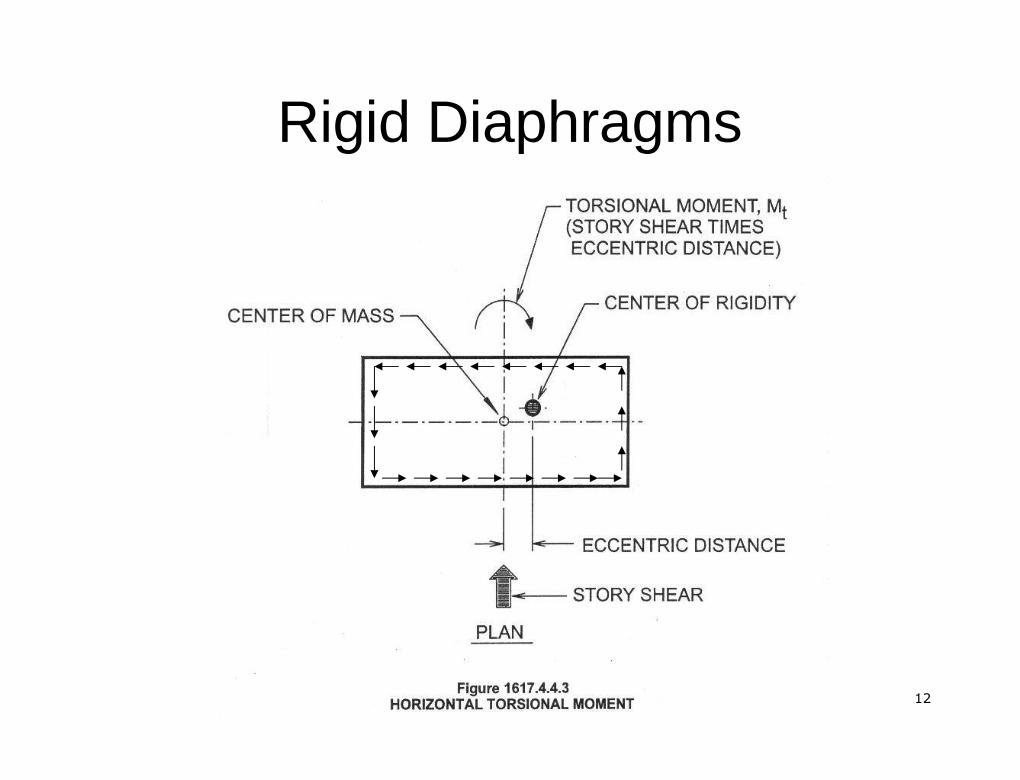
Distance between center ofDistance between center ofmass and center of rigidity, e,mass and center of rigidity, e,produces aproduces a torsionaltorsional momentmomentunder seismic lateral loadunder seismic lateral load
1212
Rigid DiaphragmsRigid Diaphragms

1313
Rigid DiaphragmsRigid Diaphragms
The lateral force is distributed to vertical lateralThe lateral force is distributed to vertical lateralforce resisting elements accounting for directforce resisting elements accounting for directshear andshear and torsionaltorsional shear using the equations:shear using the equations:
JJrr = relative polar moment of= relative polar moment of intertiaintertia== (R(Rixixyy’’22+R+Riyiyxx’’22))
xpyr
iypy
iy
iy
iy eFJ
x'RF
R
RV
∑
ypxr
ixpx
ix
ixix eF
Jy'R
FR
RV
∑

1414
Load CombinationsLoad Combinations
Section 1605Section 16051605.2 Strength Design1605.2 Strength Design1605.3 Allowable Stress Design1605.3 Allowable Stress Design1605.3.3 Alternate Basic Load Combinations1605.3.3 Alternate Basic Load Combinations•• ASD Load CombinationASD Load Combination•• Increase in allowable stress permittedIncrease in allowable stress permitted
1515
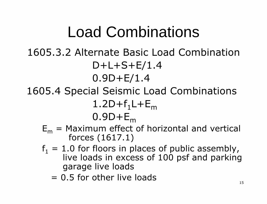
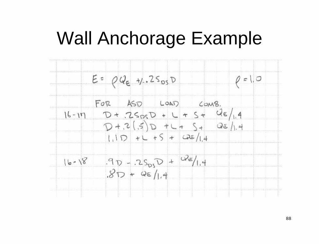
Load CombinationsLoad Combinations1605.3.2 Alternate Basic Load Combination1605.3.2 Alternate Basic Load Combination
D+L+S+E/1.4D+L+S+E/1.40.9D+E/1.40.9D+E/1.4
1605.4 Special Seismic Load Combinations1605.4 Special Seismic Load Combinations1.2D+f1.2D+f11L+EL+Emm0.9D+E0.9D+Emm
EEmm = Maximum effect of horizontal and vertical= Maximum effect of horizontal and verticalforces (1617.1)forces (1617.1)
ff11 = 1.0 for floors in places of public assembly,= 1.0 for floors in places of public assembly,live loads in excess of 100live loads in excess of 100 psfpsf and parkingand parkinggarage live loadsgarage live loads
= 0.5 for other live loads= 0.5 for other live loads
1616
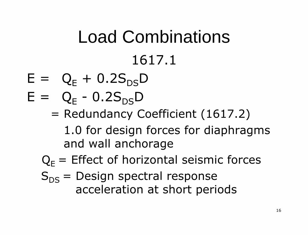
Load CombinationsLoad Combinations1617.11617.1
E =E = QQEE + 0.2S+ 0.2SDSDSDDE =E = QQEE -- 0.2S0.2SDSDSDD
= Redundancy Coefficient (1617.2)= Redundancy Coefficient (1617.2)1.0 for design forces for diaphragms1.0 for design forces for diaphragmsand wall anchorageand wall anchorage
QQEE = Effect of horizontal seismic forces= Effect of horizontal seismic forcesSSDSDS = Design spectral response= Design spectral response
acceleration at short periodsacceleration at short periods
1717
Load CombinationsLoad Combinations
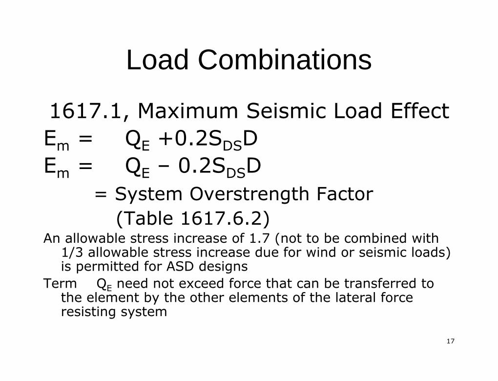
1617.1, Maximum Seismic Load Effect1617.1, Maximum Seismic Load EffectEEmm == QQEE +0.2S+0.2SDSDSDDEEmm == QQEE –– 0.2S0.2SDSDSDD
= System= System OverstrengthOverstrength FactorFactor(Table 1617.6.2)(Table 1617.6.2)
An allowable stress increase of 1.7 (not to be combined withAn allowable stress increase of 1.7 (not to be combined with1/3 allowable stress increase due for wind or seismic loads)1/3 allowable stress increase due for wind or seismic loads)is permitted for ASD designsis permitted for ASD designs
TermTerm QQEE need not exceed force that can be transferred toneed not exceed force that can be transferred tothe element by the other elements of the lateral forcethe element by the other elements of the lateral forceresisting systemresisting system
1818
Load CombinationsLoad Combinations
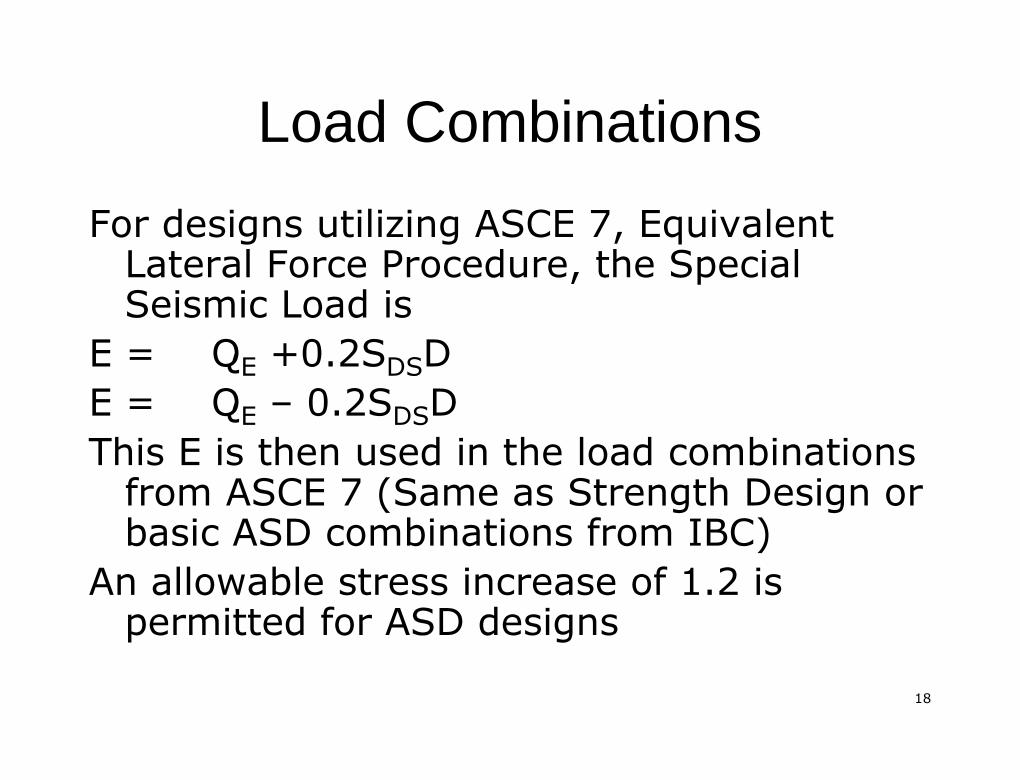
For designs utilizing ASCE 7, EquivalentFor designs utilizing ASCE 7, EquivalentLateral Force Procedure, the SpecialLateral Force Procedure, the SpecialSeismic Load isSeismic Load is
E =E = QQEE +0.2S+0.2SDSDSDDE =E = QQEE –– 0.2S0.2SDSDSDDThis E is then used in the load combinationsThis E is then used in the load combinations
from ASCE 7 (Same as Strength Design orfrom ASCE 7 (Same as Strength Design orbasic ASD combinations from IBC)basic ASD combinations from IBC)
An allowable stress increase of 1.2 isAn allowable stress increase of 1.2 ispermitted for ASD designspermitted for ASD designs
1919
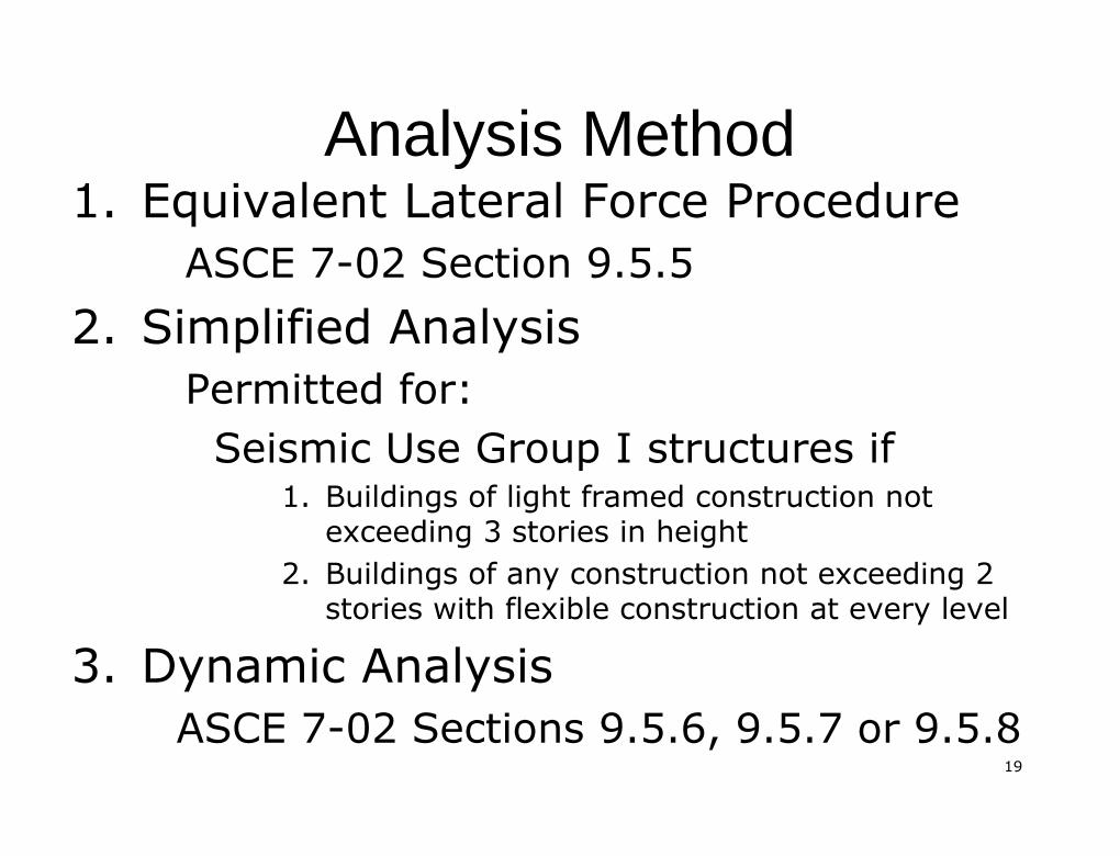
Analysis MethodAnalysis Method1.1. Equivalent Lateral Force ProcedureEquivalent Lateral Force Procedure
ASCE 7ASCE 7--02 Section 9.5.502 Section 9.5.52.2. Simplified AnalysisSimplified Analysis
Permitted for:Permitted for:Seismic Use Group I structures ifSeismic Use Group I structures if
1.1. Buildings of light framed construction notBuildings of light framed construction notexceeding 3 stories in heightexceeding 3 stories in height
2.2. Buildings of any construction not exceeding 2Buildings of any construction not exceeding 2stories with flexible construction at every levelstories with flexible construction at every level
3.3. Dynamic AnalysisDynamic AnalysisASCE 7ASCE 7--02 Sections 9.5.6, 9.5.7 or 9.5.802 Sections 9.5.6, 9.5.7 or 9.5.8
2020
Analysis MethodAnalysis Method
For structures designed using theFor structures designed using theSimplified Analysis Procedures, theSimplified Analysis Procedures, therequirements of Sections 1620.2requirements of Sections 1620.2--1620.5 (IBC) must be met.1620.5 (IBC) must be met.
Exception: Structures in SDC AException: Structures in SDC AFor structures designed using theFor structures designed using the
Equivalent Lateral Force Procedure,Equivalent Lateral Force Procedure,the requirements of 9.5.2.6 (ASCE 7)the requirements of 9.5.2.6 (ASCE 7)must be metmust be met
2121
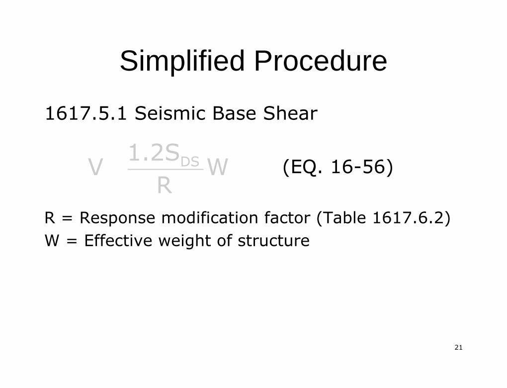
Simplified ProcedureSimplified Procedure
1617.5.1 Seismic Base Shear1617.5.1 Seismic Base Shear
(EQ. 16(EQ. 16--56)56)
R = Response modification factor (Table 1617.6.2)R = Response modification factor (Table 1617.6.2)W = Effective weight of structureW = Effective weight of structure
WR1.2SV DS

2222
Simplified ProcedureSimplified Procedure
1617.5.2 Vertical Distribution of Horizontal1617.5.2 Vertical Distribution of HorizontalForcesForces
(EQ. 16(EQ. 16--57)57)
wwxx = Portion of effective weight of structure,= Portion of effective weight of structure,W, at Level x.W, at Level x.
xDS
x wR1.2SF
2323
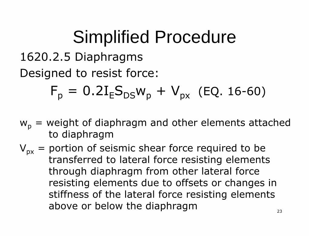
Simplified ProcedureSimplified Procedure1620.2.5 Diaphragms1620.2.5 DiaphragmsDesigned to resist force:Designed to resist force:
FFpp = 0.2I= 0.2IEESSDSDSwwpp ++ VVpxpx (EQ. 16(EQ. 16--60)60)
wwpp = weight of diaphragm and other elements attached= weight of diaphragm and other elements attachedto diaphragmto diaphragm
VVpxpx = portion of seismic shear force required to be= portion of seismic shear force required to betransferred to lateral force resisting elementstransferred to lateral force resisting elementsthrough diaphragm from other lateral forcethrough diaphragm from other lateral forceresisting elements due to offsets or changes inresisting elements due to offsets or changes instiffness of the lateral force resisting elementsstiffness of the lateral force resisting elementsabove or below the diaphragmabove or below the diaphragm

2424
Simplified ProcedureSimplified Procedure
2525
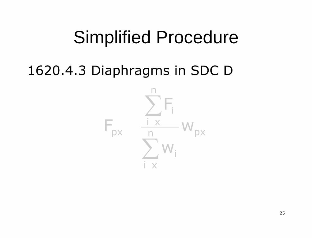
Simplified ProcedureSimplified Procedure
1620.4.3 Diaphragms in SDC D1620.4.3 Diaphragms in SDC D
pxn
xii
n
xii
px ww
FF
∑∑
2626
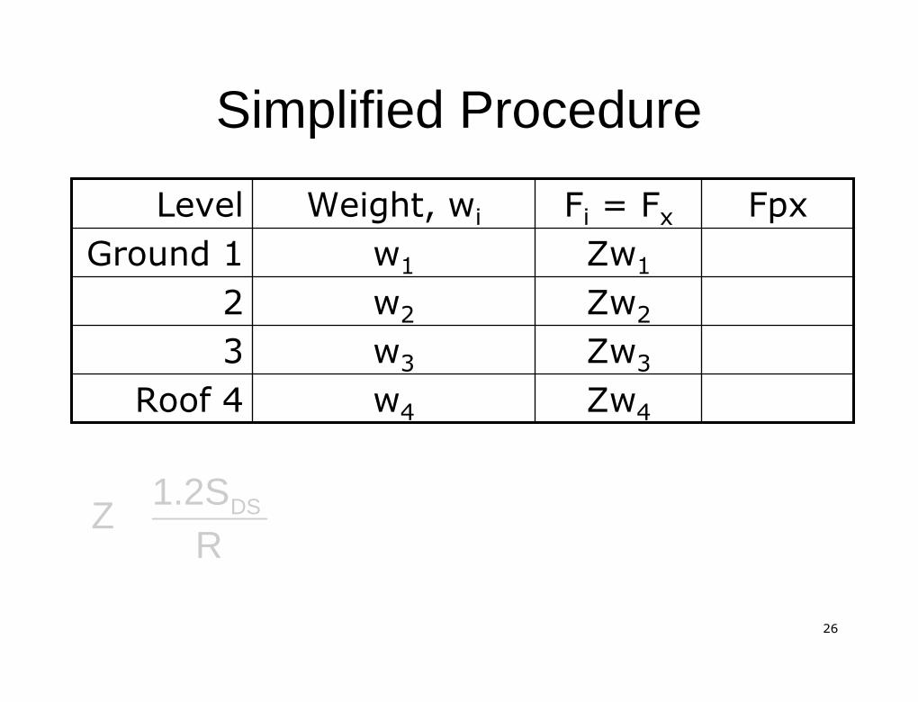
Simplified ProcedureSimplified Procedure
ZwZw44ww44Roof 4Roof 4ZwZw33ww3333ZwZw22ww2222ZwZw11ww11Ground 1Ground 1
FpxFpxFFii == FFxxWeight,Weight, wwiiLevelLevel
R1.2S
Z DS

2727
Simplified ProcedureSimplified Procedure
pxn
xii
n
xii
px ww
FF
∑∑
14321
4321p1 wwwww
ZwZwZwZwF
1143214321 Zww)www(w)wwwZ(w
2828
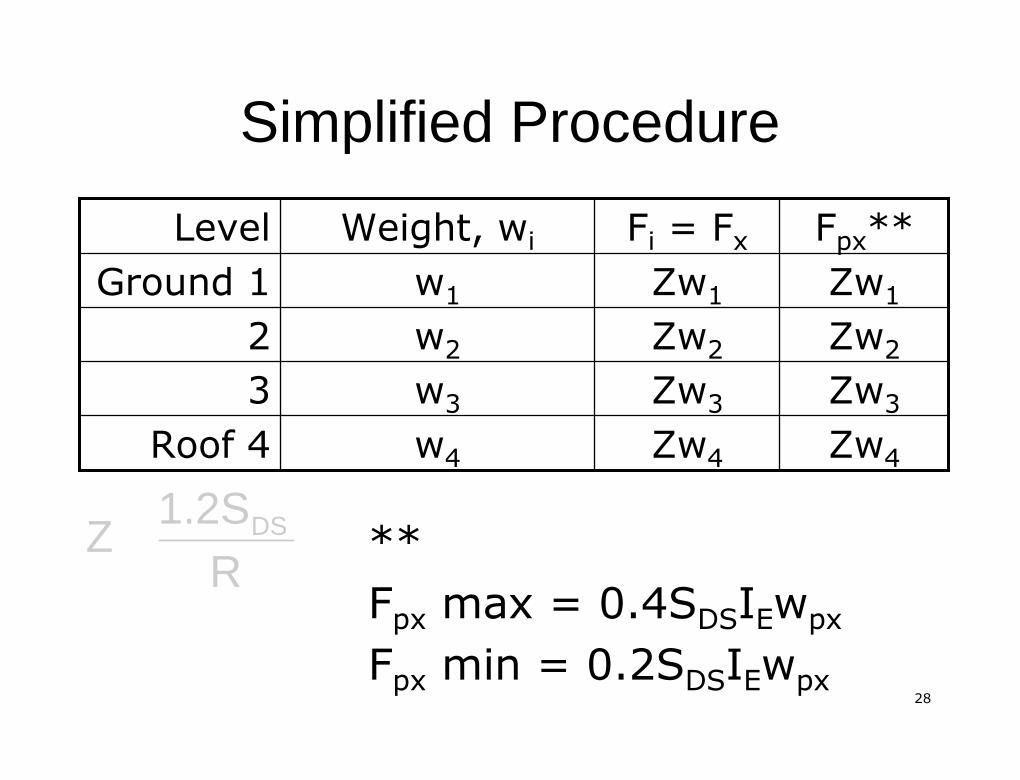
Simplified ProcedureSimplified Procedure
ZwZw44ZwZw44ww44Roof 4Roof 4ZwZw33ZwZw33ww3333ZwZw22ZwZw22ww2222ZwZw11ZwZw11ww11Ground 1Ground 1
FFpxpx****FFii == FFxxWeight,Weight, wwiiLevelLevel
R1.2S
Z DS ****FFpxpx max = 0.4Smax = 0.4SDSDSIIEEwwpxpxFFpxpx min = 0.2Smin = 0.2SDSDSIIEEwwpxpx
2929
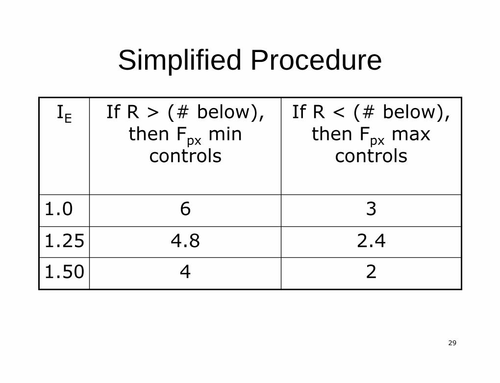
Simplified ProcedureSimplified Procedure
2.42.44.84.81.251.2522441.501.50
33661.01.0
If R < (# below),If R < (# below),thenthen FFpxpx maxmax
controlscontrolsIf R > (# below),If R > (# below),
thenthen FFpxpx minmincontrolscontrols
IIEE
3030
Equivalent Lateral Force ProcedureEquivalent Lateral Force Procedure
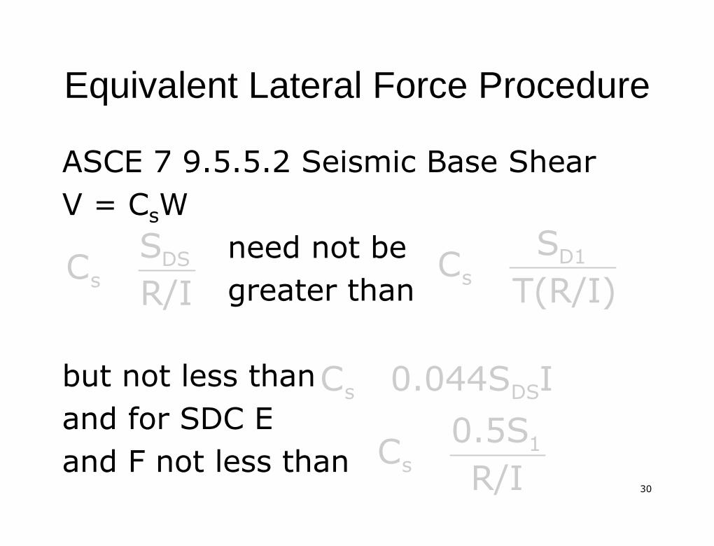
ASCE 7 9.5.5.2 Seismic Base ShearASCE 7 9.5.5.2 Seismic Base ShearV =V = CCssWW
need not beneed not begreater thangreater than
but not less thanbut not less thanand for SDC Eand for SDC Eand F not less thanand F not less than
R/ISC DS
s T(R/I)SC D1
s
I0.044SC DSs
R/I0.5SC 1
s
3131
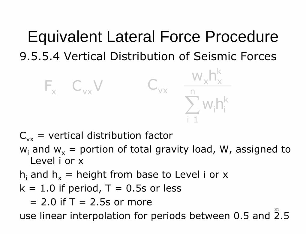
Equivalent Lateral Force ProcedureEquivalent Lateral Force Procedure9.5.5.4 Vertical Distribution of Seismic Forces9.5.5.4 Vertical Distribution of Seismic Forces
CCvxvx = vertical distribution factor= vertical distribution factorwwii andand wwxx = portion of total gravity load, W, assigned to= portion of total gravity load, W, assigned to
Level i or xLevel i or xhhii andand hhxx = height from base to Level i or x= height from base to Level i or xk = 1.0 if period, T = 0.5s or lessk = 1.0 if period, T = 0.5s or less
= 2.0 if T = 2.5s or more= 2.0 if T = 2.5s or moreuse linear interpolation for periods between 0.5 and 2.5use linear interpolation for periods between 0.5 and 2.5
VCF vxx ∑n1i
kii
kxx
vxhw
hwC
3232
Equivalent Lateral Force ProcedureEquivalent Lateral Force Procedure
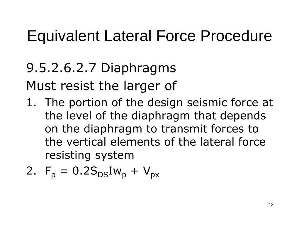
9.5.2.6.2.7 Diaphragms9.5.2.6.2.7 DiaphragmsMust resist the larger ofMust resist the larger of1.1. The portion of the design seismic force atThe portion of the design seismic force at
the level of the diaphragm that dependsthe level of the diaphragm that dependson the diaphragm to transmit forces toon the diaphragm to transmit forces tothe vertical elements of the lateral forcethe vertical elements of the lateral forceresisting systemresisting system
2.2. FFpp = 0.2S= 0.2SDSDSIwIwpp ++ VVpxpx
3333
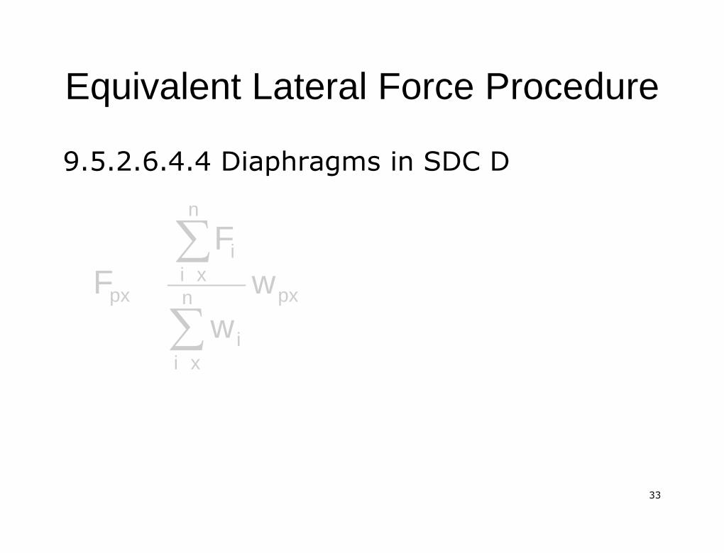
Equivalent Lateral Force ProcedureEquivalent Lateral Force Procedure
9.5.2.6.4.4 Diaphragms in SDC D9.5.2.6.4.4 Diaphragms in SDC D
pxn
xii
n
xii
px ww
FF
∑∑
3434
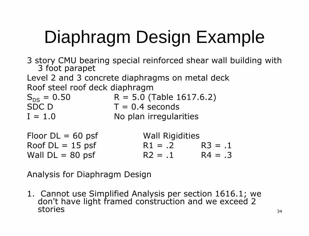
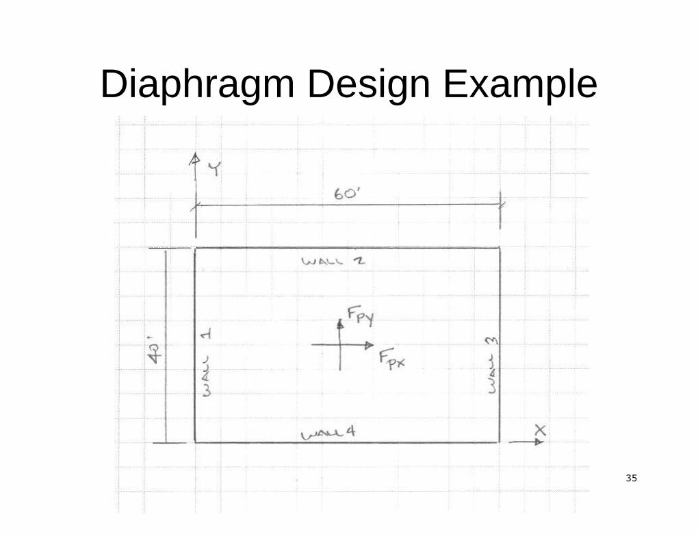
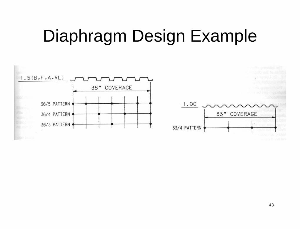
Diaphragm Design ExampleDiaphragm Design Example3 story CMU bearing special reinforced shear wall building with3 story CMU bearing special reinforced shear wall building with3 foot parapet3 foot parapetLevel 2 and 3 concrete diaphragms on metal deckLevel 2 and 3 concrete diaphragms on metal deckRoof steel roof deck diaphragmRoof steel roof deck diaphragmSSDSDS = 0.50= 0.50 R = 5.0 (Table 1617.6.2)R = 5.0 (Table 1617.6.2)SDC DSDC D T = 0.4 secondsT = 0.4 secondsI = 1.0I = 1.0 No plan irregularitiesNo plan irregularitiesFloor DL = 60Floor DL = 60 psfpsf Wall RigiditiesWall RigiditiesRoof DL = 15Roof DL = 15 psfpsf R1 = .2R1 = .2 R3 = .1R3 = .1Wall DL = 80Wall DL = 80 psfpsf R2 = .1R2 = .1 R4 = .3R4 = .3Analysis for Diaphragm DesignAnalysis for Diaphragm Design1. Cannot use Simplified Analysis per section 1616.1; we1. Cannot use Simplified Analysis per section 1616.1; wedon't have light framed construction and we exceed 2don't have light framed construction and we exceed 2storiesstories
3535
Diaphragm Design ExampleDiaphragm Design Example
3636
Diaphragm Design ExampleDiaphragm Design Example
3737
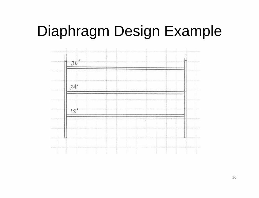
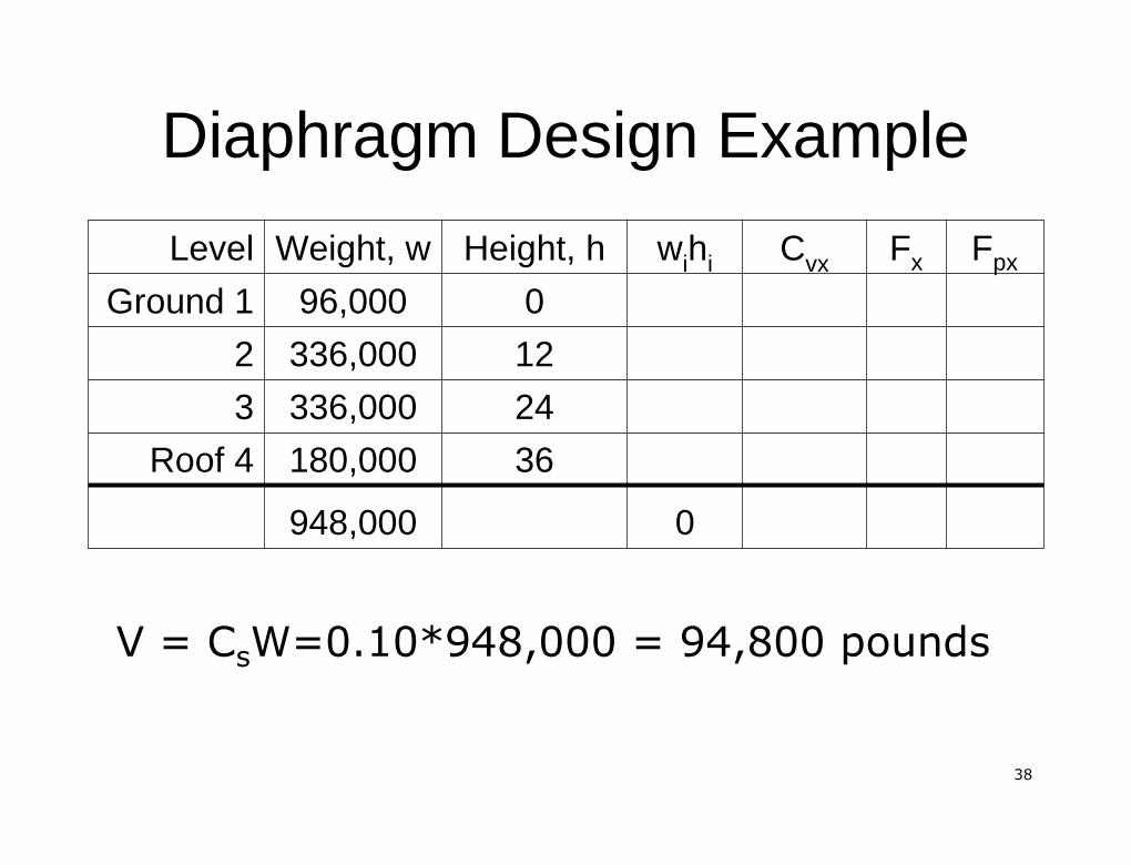
Diaphragm Design ExampleDiaphragm Design Example2. Using the Equivalent Lateral Force Procedure from ASCE 72. Using the Equivalent Lateral Force Procedure from ASCE 7--02,02,find the base shearfind the base shearV =V = CCssWW ((EqEq. 9.5.5.2. 9.5.5.2--1)1)Weight tributary to level 1 = 80psf*12'/2*(2*40'+2*60') = 96,000Weight tributary to level 1 = 80psf*12'/2*(2*40'+2*60') = 96,000 poundspoundsWeight tributary to level 2 and 3 = 80psf*12'*(2*40'+2*60') + 60Weight tributary to level 2 and 3 = 80psf*12'*(2*40'+2*60') + 60psf*(40'*60')=psf*(40'*60')=336,000 pounds336,000 poundsWeight tributary to level 4 = 80psf*(12'/2+3)*(2*40'+2*60') + 15Weight tributary to level 4 = 80psf*(12'/2+3)*(2*40'+2*60') + 15psf*(40'*60') =psf*(40'*60') =180,000 pounds180,000 pounds
CCss = S= SDSDS/(R/I) = .50/(5/1) = 0.10/(R/I) = .50/(5/1) = 0.10CHECK OTHER CCHECK OTHER Css EQUATIONSEQUATIONS
3838
Diaphragm Design ExampleDiaphragm Design Example
0948,000
36180,000Roof 4
24336,0003
12336,0002
096,000Ground 1
FpxFxCvxwihiHeight, hWeight, wLevel
V =V = CCssWW=0.10*948,000 = 94,800 pounds=0.10*948,000 = 94,800 pounds

3939
Diaphragm Design ExampleDiaphragm Design Example
3. Determine the vertical distribution of Seismic Forces3. Determine the vertical distribution of Seismic Forces
FFxx == CCvxvxVV
k = 1 (T<0.5)k = 1 (T<0.5) ∑n
1i
kii
kxx
vx
hw
hwC
18576000948,000
330700.3488648000036180,000Roof 4
411530.4341806400024336,0003
205770.2171403200012336,0002
000096,000Ground 1
FpxFxCvxwihiHeight, hWeight, wLevel
4040
Diaphragm Design ExampleDiaphragm Design Example
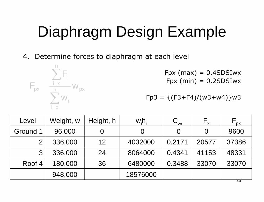
4. Determine forces to diaphragm at each level4. Determine forces to diaphragm at each levelFpxFpx (max) = 0.4SDSIwx(max) = 0.4SDSIwxFpxFpx (min) = 0.2SDSIwx(min) = 0.2SDSIwx
Fp3 = {(F3+F4)/(w3+w4)}w3Fp3 = {(F3+F4)/(w3+w4)}w3pxn
xii
n
xii
px ww
FF
∑∑
18576000948,000
33070330700.3488648000036180,000Roof 4
48331411530.4341806400024336,0003
37386205770.2171403200012336,0002
9600000096,000Ground 1
FpxFxCvxwihiHeight, hWeight, wLevel
4141
Diaphragm Design ExampleDiaphragm Design Example
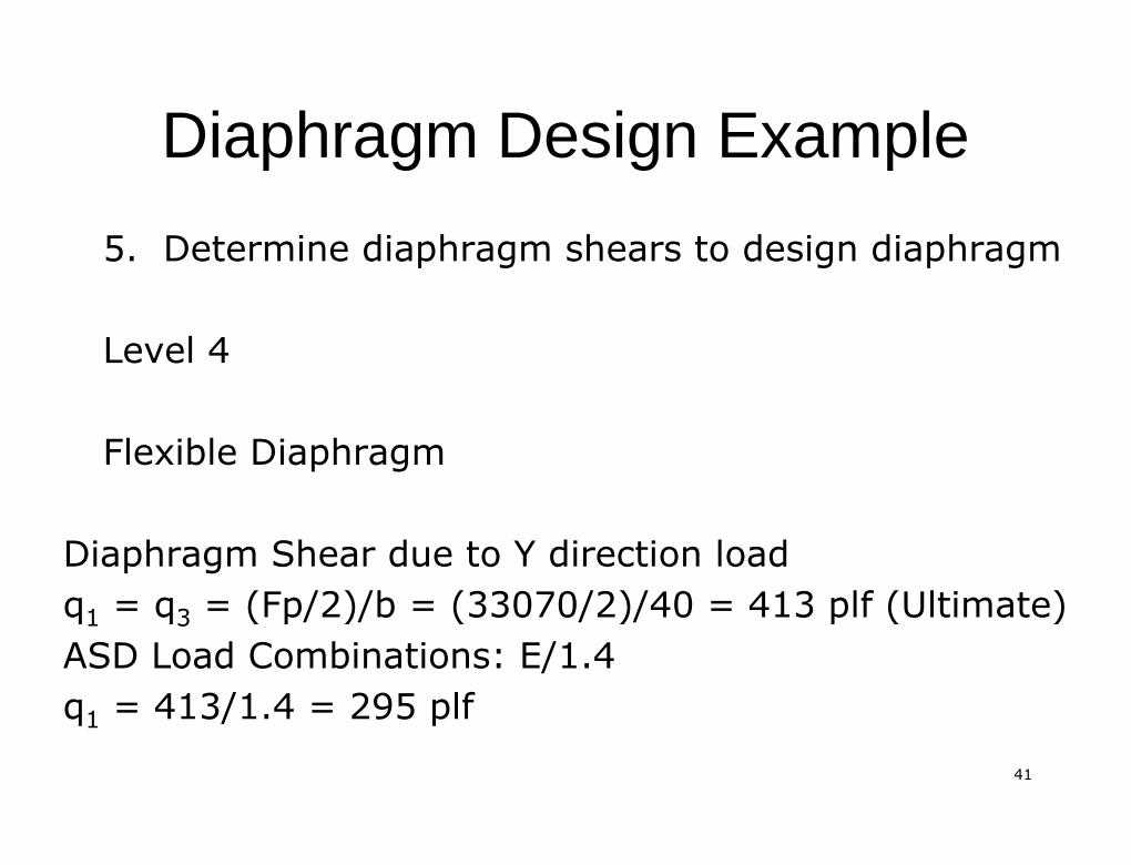
5. Determine diaphragm shears to design diaphragm5. Determine diaphragm shears to design diaphragm
Level 4Level 4
Flexible DiaphragmFlexible Diaphragm
Diaphragm Shear due to Y direction loadDiaphragm Shear due to Y direction loadqq11 = q= q33 = (Fp/2)/b = (33070/2)/40 = 413= (Fp/2)/b = (33070/2)/40 = 413 plfplf (Ultimate)(Ultimate)ASD Load Combinations: E/1.4ASD Load Combinations: E/1.4qq11 = 413/1.4 = 295= 413/1.4 = 295 plfplf
4242
Diaphragm Design ExampleDiaphragm Design Example
4343
Diaphragm Design ExampleDiaphragm Design Example

4444
Diaphragm Design ExampleDiaphragm Design ExampleLevel 3 Rigid DiaphragmLevel 3 Rigid DiaphragmCenter of RigidityCenter of Rigidityxxrr == RRyiyixxii// RRyiyi = (R1(0)+R3(60))/(R1+R3)= (R1(0)+R3(60))/(R1+R3)
= (0.20*(0)+0.10*(60))/(0.20+0.10)= (0.20*(0)+0.10*(60))/(0.20+0.10)xxrr = 20 feet= 20 feetyyrr == RRxixiyyii// RRxixi = (R2(40)+R4(0))/(R2+R4)= (R2(40)+R4(0))/(R2+R4)
= (0.10*(40)+0.30*(0))/(0.10+0.30) == (0.10*(40)+0.30*(0))/(0.10+0.30) =yyrr = 10 feet= 10 feet
Center of Mass = center of diaphragmCenter of Mass = center of diaphragmeexx = 30= 30--20 = 10 feet plus 5% accidental torsion20 = 10 feet plus 5% accidental torsioneexx = 10 +0.5*60 = 13 feet= 10 +0.5*60 = 13 feet
4545
Diaphragm Design ExampleDiaphragm Design Example
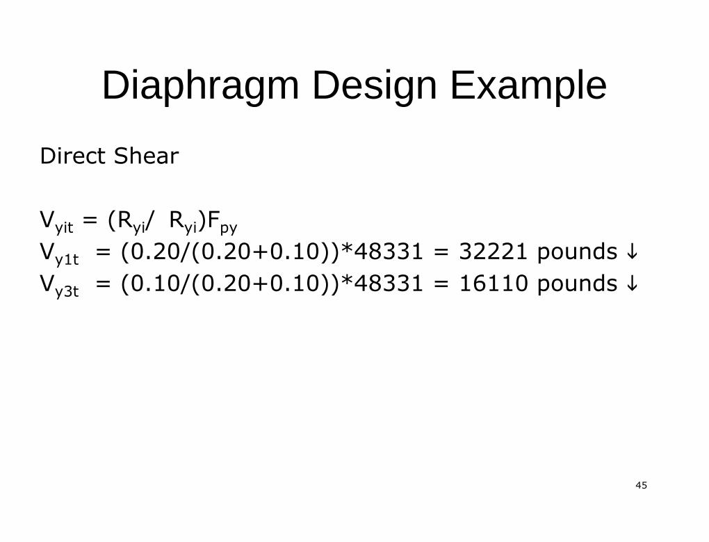
Direct ShearDirect Shear
VVyityit = (= (RRyiyi// RRyiyi)F)FpypyVVy1ty1t = (0.20/(0.20+0.10))*48331 = 32221 pounds= (0.20/(0.20+0.10))*48331 = 32221 pounds ��VVy3ty3t = (0.10/(0.20+0.10))*48331 = 16110 pounds= (0.10/(0.20+0.10))*48331 = 16110 pounds ��
4646
Diaphragm Design ExampleDiaphragm Design Example
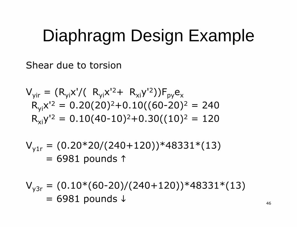
Shear due to torsionShear due to torsion
VVyiryir = (R= (Ryiyix'/(x'/( RRyiyix'x'22++ RRxixiy'y'22))F))FpypyeexxRRyiyix'x'22 = 0.20(20)= 0.20(20)22+0.10((60+0.10((60--20)20)22 = 240= 240RRxixiy'y'22 = 0.10(40= 0.10(40--10)10)22+0.30((10)+0.30((10)22 = 120= 120
VVy1ry1r = (0.20*20/(240+120))*48331*(13)= (0.20*20/(240+120))*48331*(13)= 6981 pounds= 6981 pounds ��
VVy3ry3r = (0.10*(60= (0.10*(60--20)/(240+120))*48331*(13)20)/(240+120))*48331*(13)= 6981 pounds= 6981 pounds ��
4747
Diaphragm Design ExampleDiaphragm Design Example
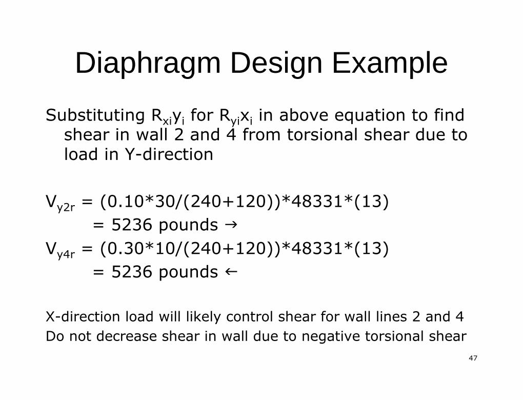
SubstitutingSubstituting RRxixiyyii forfor RRyiyixxii in above equation to findin above equation to findshear in wall 2 and 4 fromshear in wall 2 and 4 from torsionaltorsional shear due toshear due toload in Yload in Y--directiondirection
VVy2ry2r = (0.10*30/(240+120))*48331*(13)= (0.10*30/(240+120))*48331*(13)= 5236 pounds= 5236 pounds ��
VVy4ry4r = (0.30*10/(240+120))*48331*(13)= (0.30*10/(240+120))*48331*(13)= 5236 pounds= 5236 pounds ��
XX--direction load will likely control shear for wall lines 2 and 4direction load will likely control shear for wall lines 2 and 4Do not decrease shear in wall due to negativeDo not decrease shear in wall due to negative torsionaltorsional shearshear
4848
Diaphragm Design ExampleDiaphragm Design Example
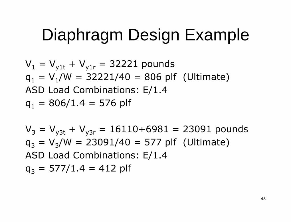
VV11 = V= Vy1ty1t + V+ Vy1ry1r = 32221 pounds= 32221 poundsqq11 = V= V11/W = 32221/40 = 806/W = 32221/40 = 806 plfplf (Ultimate)(Ultimate)ASD Load Combinations: E/1.4ASD Load Combinations: E/1.4qq11 = 806/1.4 = 576= 806/1.4 = 576 plfplf
VV33 = V= Vy3ty3t + V+ Vy3ry3r = 16110+6981 = 23091 pounds= 16110+6981 = 23091 poundsqq33 = V= V33/W = 23091/40 = 577/W = 23091/40 = 577 plfplf (Ultimate)(Ultimate)ASD Load Combinations: E/1.4ASD Load Combinations: E/1.4qq33 = 577/1.4 = 412= 577/1.4 = 412 plfplf

4949
Diaphragm Design ExampleDiaphragm Design Example
5050
Diaphragms with OpeningsDiaphragms with Openings
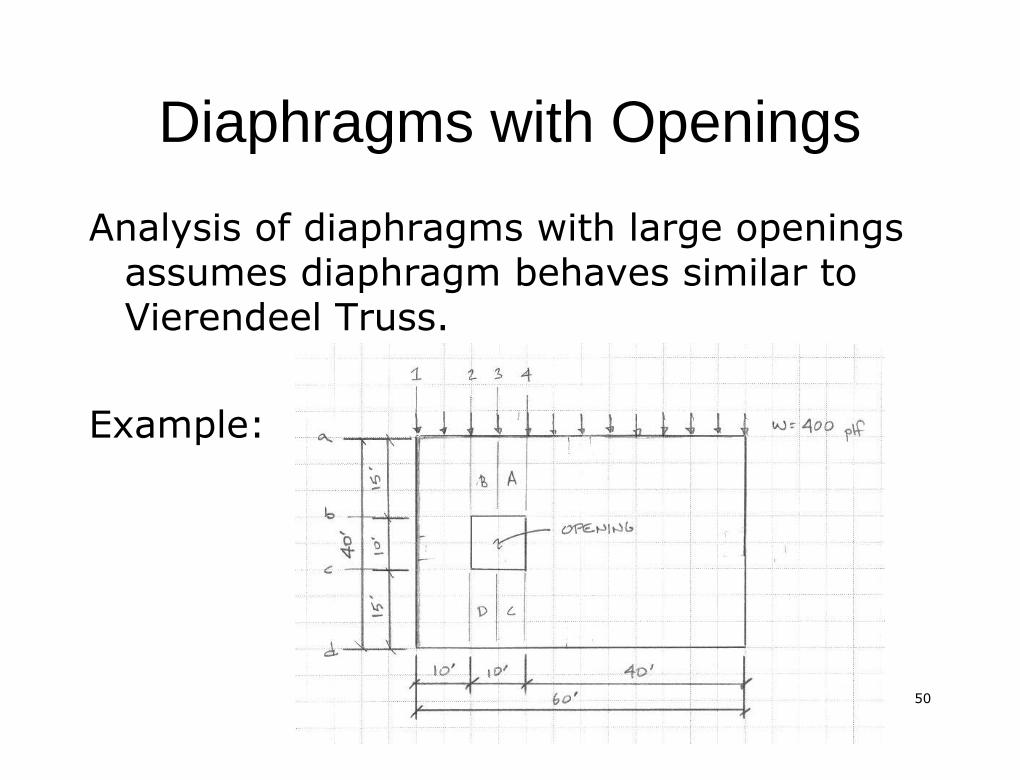
Analysis of diaphragms with large openingsAnalysis of diaphragms with large openingsassumes diaphragm behaves similar toassumes diaphragm behaves similar toVierendeelVierendeel Truss.Truss.
Example:Example:
5151
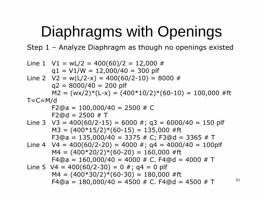
Diaphragms with OpeningsDiaphragms with OpeningsStep 1Step 1 –– Analyze Diaphragm as though no openings existedAnalyze Diaphragm as though no openings existedLine 1Line 1 V1 = wL/2 = 400(60)/2 = 12,000 #V1 = wL/2 = 400(60)/2 = 12,000 #
q1 = V1/W = 12,000/40 = 300q1 = V1/W = 12,000/40 = 300 plfplfLine 2Line 2 V2 = w(L/2V2 = w(L/2--x) = 400(60/2x) = 400(60/2--10) = 8000 #10) = 8000 #
q2 = 8000/40 = 200q2 = 8000/40 = 200 plfplfM2 = (wx/2)*(LM2 = (wx/2)*(L--x) = (400*10/2)*(60x) = (400*10/2)*(60--10) = 100,000 #ft10) = 100,000 #ft
T=C=M/dT=C=M/dF2@a = 100,000/40 = 2500 # CF2@a = 100,000/40 = 2500 # CF2@d = 2500 # TF2@d = 2500 # T
Line 3Line 3 V3 = 400(60/2V3 = 400(60/2--15) = 6000 #; q3 = 6000/40 = 15015) = 6000 #; q3 = 6000/40 = 150 plfplfM3 = (400*15/2)*(60M3 = (400*15/2)*(60--15) = 135,000 #ft15) = 135,000 #ftF3@a = 135,000/40 = 3375 # C; F3@d = 3365 # TF3@a = 135,000/40 = 3375 # C; F3@d = 3365 # T
Line 4Line 4 V4 = 400(60/2V4 = 400(60/2--20) = 4000 #; q4 = 4000/40 = 100plf20) = 4000 #; q4 = 4000/40 = 100plfM4 = (400*20/2)*(60M4 = (400*20/2)*(60--20) = 160,000 #ft20) = 160,000 #ftF4@a = 160,000/40 = 4000 # C. F4@d = 4000 # TF4@a = 160,000/40 = 4000 # C. F4@d = 4000 # T
Line 5 V4 = 400(60/2Line 5 V4 = 400(60/2--30) = 0 #; q4 = 030) = 0 #; q4 = 0 plfplfM4 = (400*30/2)*(60M4 = (400*30/2)*(60--30) = 180,000 #ft30) = 180,000 #ftF4@a = 180,000/40 = 4500 # C. F4@d = 4500 # TF4@a = 180,000/40 = 4500 # C. F4@d = 4500 # T
5252
Diaphragms with Diaphragms with OpeningsOpenings
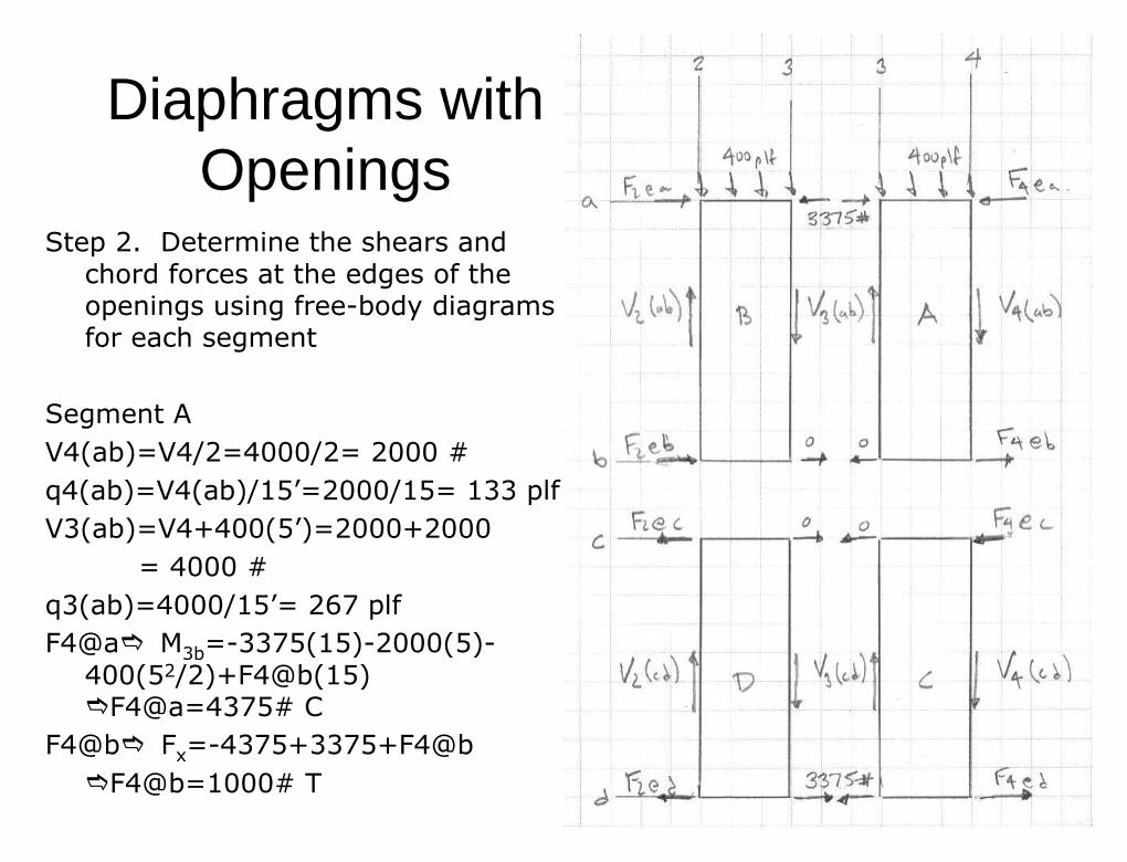
Step 2. Determine the shears andStep 2. Determine the shears andchord forces at the edges of thechord forces at the edges of theopenings using freeopenings using free--body diagramsbody diagramsfor each segmentfor each segment
Segment ASegment AV4(ab)=V4/2=4000/2= 2000 #V4(ab)=V4/2=4000/2= 2000 #q4(ab)=V4(ab)/15q4(ab)=V4(ab)/15’’=2000/15= 133=2000/15= 133 plfplfV3(ab)=V4+400(5V3(ab)=V4+400(5’’)=2000+2000)=2000+2000
= 4000 #= 4000 #q3(ab)=4000/15q3(ab)=4000/15’’= 267= 267 plfplfF4@aF4@a�� MM3b3b==--3375(15)3375(15)--2000(5)2000(5)--
400(5400(522/2)+F4@b(15)/2)+F4@b(15)��F4@a=4375# CF4@a=4375# C
F4@bF4@b�� FFxx==--4375+3375+F4@b4375+3375+F4@b��F4@b=1000# TF4@b=1000# T
5353
Diaphragms with Diaphragms with OpeningsOpenings
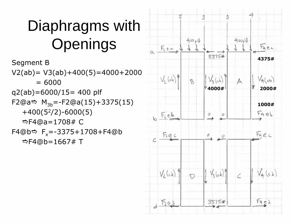
Segment BSegment BV2(ab)= V3(ab)+400(5)=4000+2000V2(ab)= V3(ab)+400(5)=4000+2000
= 6000= 6000q2(ab)=6000/15= 400q2(ab)=6000/15= 400 plfplfF2@aF2@a�� MM3b3b==--F2@a(15)+3375(15)F2@a(15)+3375(15)
+400(5+400(522/2)/2)--6000(5)6000(5)��F4@a=1708# CF4@a=1708# C
F4@bF4@b�� FFxx==--3375+1708+F4@b3375+1708+F4@b��F4@b=1667# TF4@b=1667# T
2000#2000#
4375#4375#
1000#1000#
4000#4000#
5454
Diaphragms with Diaphragms with OpeningsOpenings
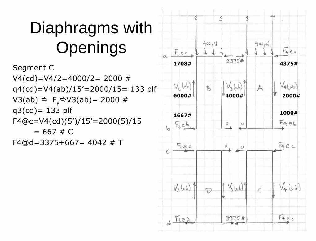
Segment CSegment CV4(cd)=V4/2=4000/2= 2000 #V4(cd)=V4/2=4000/2= 2000 #q4(cd)=V4(ab)/15q4(cd)=V4(ab)/15’’=2000/15= 133=2000/15= 133 plfplfV3(ab)V3(ab) �� FFyy��V3(ab)= 2000 #V3(ab)= 2000 #q3(cd)= 133q3(cd)= 133 plfplfF4@c=V4(cd)(5F4@c=V4(cd)(5’’)/15)/15’’=2000(5)/15=2000(5)/15
= 667 # C= 667 # CF4@d=3375+667= 4042 # TF4@d=3375+667= 4042 # T
2000#2000#
4375#4375#
1000#1000#
4000#4000#
1708#1708#
6000#6000#
1667#1667#
5555
Diaphragms with Diaphragms with OpeningsOpenings
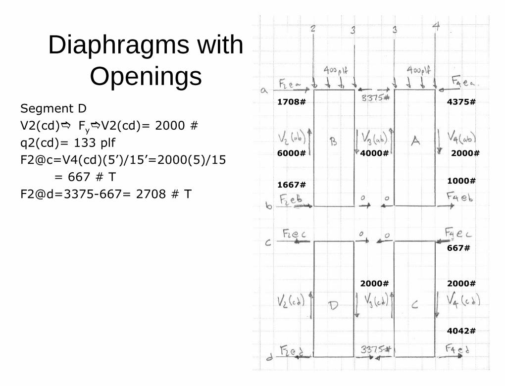
Segment DSegment DV2(cd)V2(cd)�� FFyy��V2(cd)= 2000 #V2(cd)= 2000 #q2(cd)= 133q2(cd)= 133 plfplfF2@c=V4(cd)(5F2@c=V4(cd)(5’’)/15)/15’’=2000(5)/15=2000(5)/15
= 667 # T= 667 # TF2@d=3375F2@d=3375--667= 2708 # T667= 2708 # T
2000#2000#
4375#4375#
1000#1000#
4000#4000#
1708#1708#
6000#6000#
1667#1667#
2000#2000#
667#667#
4042#4042#
2000#2000#
5656
Diaphragms with OpeningsDiaphragms with Openings
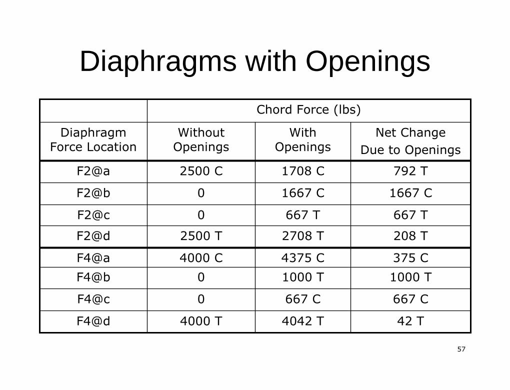
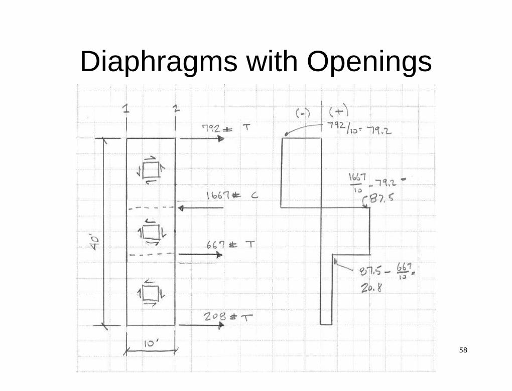
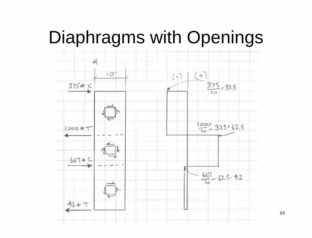
Step 3 The net change in the chord forcesStep 3 The net change in the chord forcescaused by the openings is determined bycaused by the openings is determined byadding the results of step 2 to that of theadding the results of step 2 to that of thediaphragm without openings, these netdiaphragm without openings, these netchanges must be dissipated into thechanges must be dissipated into thediaphragmdiaphragm
5757
Diaphragms with OpeningsDiaphragms with Openings
42 T42 T4042 T4042 T4000 T4000 TF4@dF4@d667 C667 C667 C667 C00F4@cF4@c1000 T1000 T1000 T1000 T00F4@bF4@b375 C375 C4375 C4375 C4000 C4000 CF4@aF4@a208 T208 T2708 T2708 T2500 T2500 TF2@dF2@d667 T667 T667 T667 T00F2@cF2@c
1667 C1667 C1667 C1667 C00F2@bF2@b792 T792 T1708 C1708 C2500 C2500 CF2@aF2@a
Net ChangeNet ChangeDue to OpeningsDue to Openings
WithWithOpeningsOpenings
WithoutWithoutOpeningsOpenings
DiaphragmDiaphragmForce LocationForce Location
Chord Force (lbs)Chord Force (lbs)
5858
Diaphragms with OpeningsDiaphragms with Openings
5959
Diaphragms with OpeningsDiaphragms with Openings
6060
Diaphragms with OpeningsDiaphragms with Openings
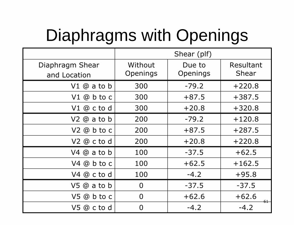
Step 4 Determine resultant shears inStep 4 Determine resultant shears indiaphragm by combining the net shearsdiaphragm by combining the net shearsdue to openings to the shears for thedue to openings to the shears for thediaphragm without openingsdiaphragm without openings
6161
Diaphragms with OpeningsDiaphragms with Openings
--4.24.2--4.24.200V5 @ c to dV5 @ c to d+62.6+62.6+62.6+62.600V5 @ b to cV5 @ b to c--37.537.5--37.537.500V5 @ a to bV5 @ a to b+95.8+95.8--4.24.2100100V4 @ c to dV4 @ c to d+162.5+162.5+62.5+62.5100100V4 @ b to cV4 @ b to c+62.5+62.5--37.537.5100100V4 @ a to bV4 @ a to b+220.8+220.8+20.8+20.8200200V2 @ c to dV2 @ c to d+287.5+287.5+87.5+87.5200200V2 @ b to cV2 @ b to c+120.8+120.8--79.279.2200200V2 @ a to bV2 @ a to b+320.8+320.8+20.8+20.8300300V1 @ c to dV1 @ c to d+387.5+387.5+87.5+87.5300300V1 @ b to cV1 @ b to c+220.8+220.8--79.279.2300300V1 @ a to bV1 @ a to b
ResultantResultantShearShear
Due toDue toOpeningsOpenings
WithoutWithoutOpeningsOpenings
Diaphragm ShearDiaphragm Shearand Locationand Location
Shear (Shear (plfplf))
6262
Diaphragms with OpeningsDiaphragms with Openings
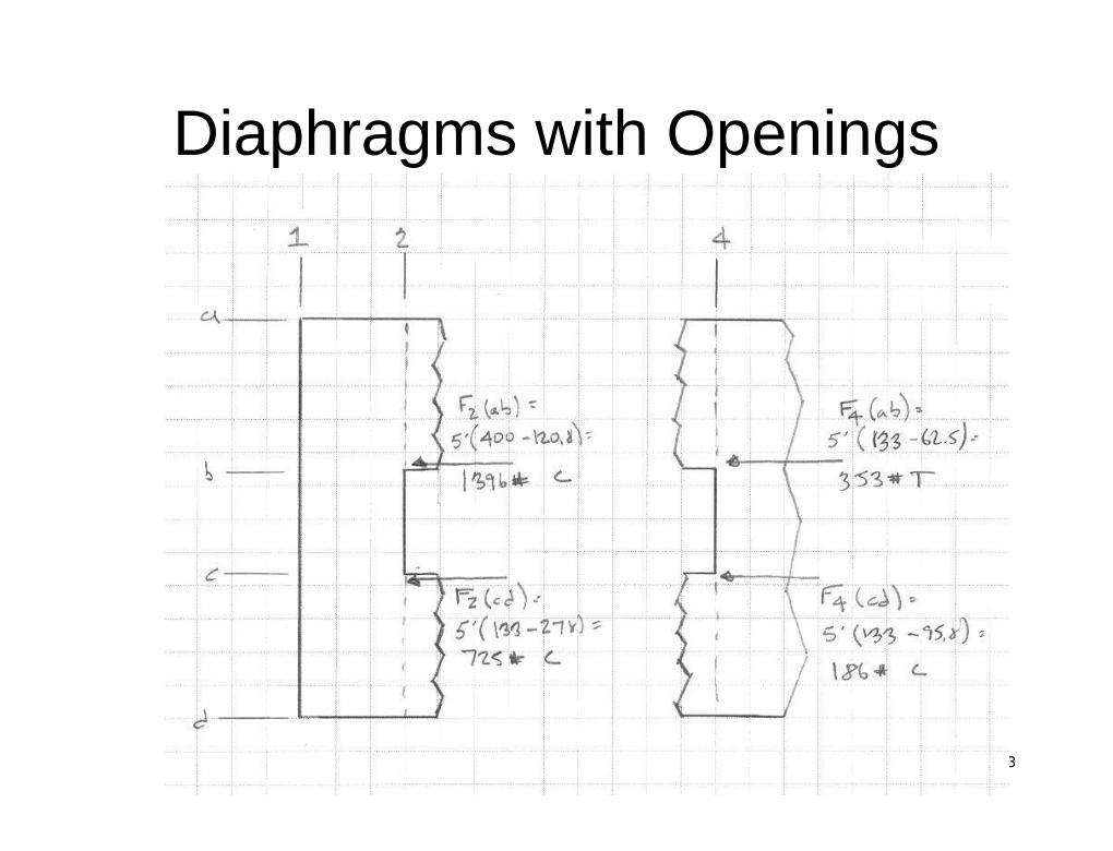
Step 5 Determine forces in the framingStep 5 Determine forces in the framingmembers in the direction perpendicular tomembers in the direction perpendicular tothe applied load by adding the shearthe applied load by adding the shearforces at the edge of the openingforces at the edge of the opening
6363
Diaphragms with OpeningsDiaphragms with Openings
6464
Other ConsiderationsOther Considerations
�� Must verify plan and verticalMust verify plan and verticalirregularities (Tables 1616.5.1.1 andirregularities (Tables 1616.5.1.1 and1616.5.5.2)1616.5.5.2)
�� Verify diaphragm requirementsVerify diaphragm requirementsspecific to material being usedspecific to material being used
6565
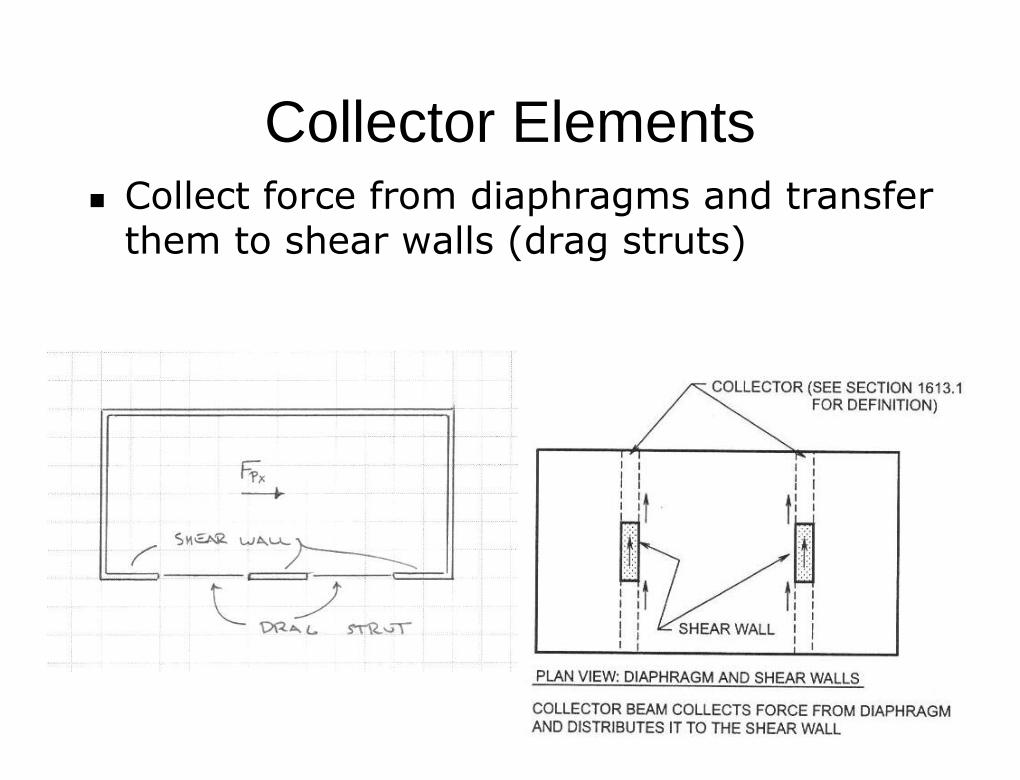
Collector ElementsCollector Elements�� Collect force from diaphragms and transferCollect force from diaphragms and transfer
them to shear walls (drag struts)them to shear walls (drag struts)
6666
Collector ElementsCollector Elements
SDC B and CSDC B and C
Must have design strength to resist theMust have design strength to resist thespecial load combinations of 1605.4special load combinations of 1605.4
Exception: Structures that use lightException: Structures that use lightframed shear walls entirelyframed shear walls entirely
Note: Collector need not be designedNote: Collector need not be designedfor a force that exceeds the forcefor a force that exceeds the forcethat can be transferred to it fromthat can be transferred to it fromother membersother members
6767
Collector ElementsCollector Elements
SDC D, E and FSDC D, E and F
Must have design strength to resist theMust have design strength to resist thespecial seismic load combinationsspecial seismic load combinations
Must resist forces in accordance withMust resist forces in accordance withdiaphragm forces required for SDC Ddiaphragm forces required for SDC D
Exception: Structures that use light framedException: Structures that use light framedshear walls entirelyshear walls entirely
Note: Collector need not be designed for aNote: Collector need not be designed for aforce that exceeds the force that can beforce that exceeds the force that can betransferred to it from other memberstransferred to it from other members
6868
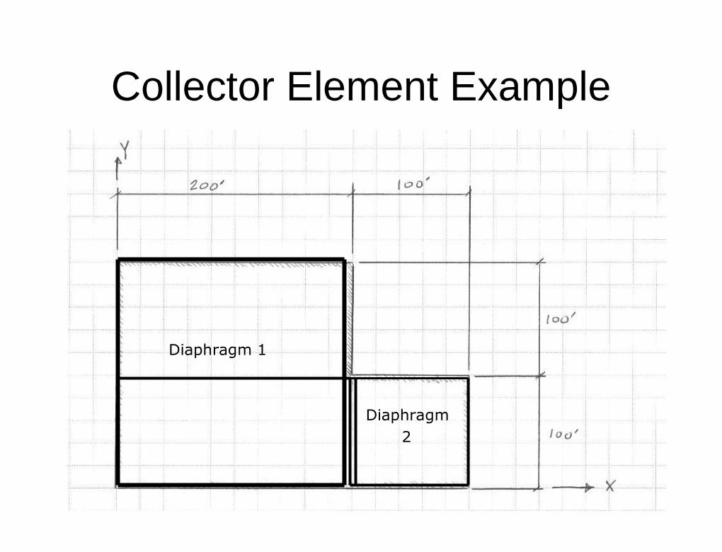
Diaphragm 1Diaphragm 1
DiaphragmDiaphragm22
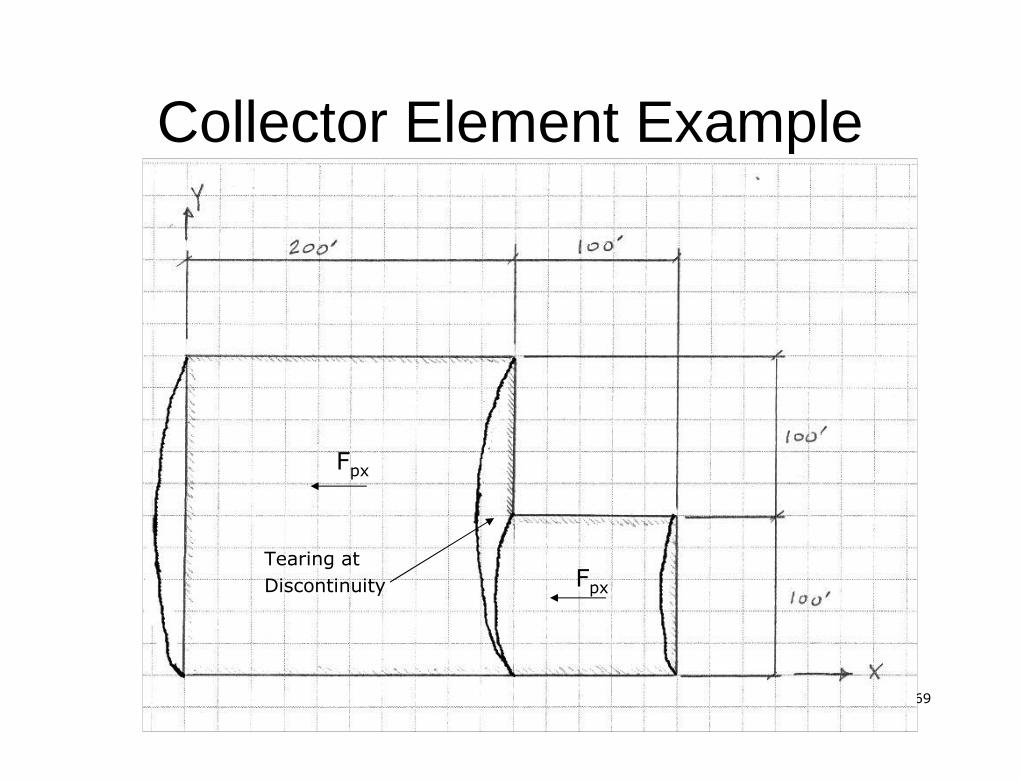
Collector Element ExampleCollector Element Example
6969
Collector Element ExampleCollector Element Example
Tearing atTearing atDiscontinuityDiscontinuity
FFpxpx
FFpxpx
7070
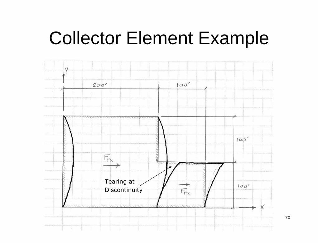
Collector Element ExampleCollector Element Example
Tearing atTearing atDiscontinuityDiscontinuity
7171
Collector Element ExampleCollector Element Example
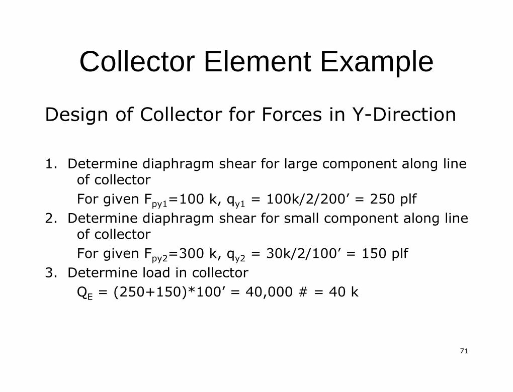
Design of Collector for Forces in YDesign of Collector for Forces in Y--DirectionDirection
1. Determine diaphragm shear for large component along line1. Determine diaphragm shear for large component along lineof collectorof collectorFor given FFor given Fpy1py1=100 k, q=100 k, qy1y1 = 100k/2/200= 100k/2/200’’ = 250= 250 plfplf
2. Determine diaphragm shear for small component along line2. Determine diaphragm shear for small component along lineof collectorof collectorFor given FFor given Fpy2py2=300 k, q=300 k, qy2y2 = 30k/2/100= 30k/2/100’’ = 150= 150 plfplf
3. Determine load in collector3. Determine load in collectorQQEE = (250+150)*100= (250+150)*100’’ = 40,000 # = 40 k= 40,000 # = 40 k
7272
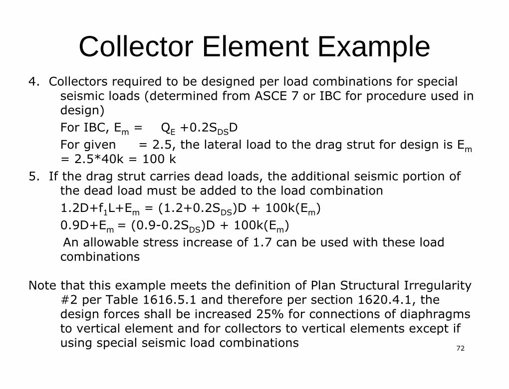
Collector Element ExampleCollector Element Example4. Collectors required to be designed per load combinations for4. Collectors required to be designed per load combinations for specialspecial
seismic loads (determined from ASCE 7 or IBC for procedure usedseismic loads (determined from ASCE 7 or IBC for procedure used inindesign)design)For IBC,For IBC, EEmm == QQEE +0.2S+0.2SDSDSDDFor givenFor given = 2.5, the lateral load to the drag strut for design is= 2.5, the lateral load to the drag strut for design is EEmm= 2.5*40k = 100 k= 2.5*40k = 100 k
5. If the drag strut carries dead loads, the additional seismic5. If the drag strut carries dead loads, the additional seismic portion ofportion ofthe dead load must be added to the load combinationthe dead load must be added to the load combination1.2D+f1.2D+f11L+EL+Emm = (1.2+0.2S= (1.2+0.2SDSDS)D + 100k(E)D + 100k(Emm))0.9D+E0.9D+Emm = (0.9= (0.9--0.2S0.2SDSDS)D + 100k(E)D + 100k(Emm))An allowable stress increase of 1.7 can be used with these loadAn allowable stress increase of 1.7 can be used with these loadcombinationscombinations
Note that this example meets the definition of Plan Structural INote that this example meets the definition of Plan Structural Irregularityrregularity#2 per Table 1616.5.1 and therefore per section 1620.4.1, the#2 per Table 1616.5.1 and therefore per section 1620.4.1, thedesign forces shall be increased 25% for connections of diaphragdesign forces shall be increased 25% for connections of diaphragmsmsto vertical element and for collectors to vertical elements exceto vertical element and for collectors to vertical elements except ifpt ifusing special seismic load combinationsusing special seismic load combinations
7373
Collector Element ExampleCollector Element Example
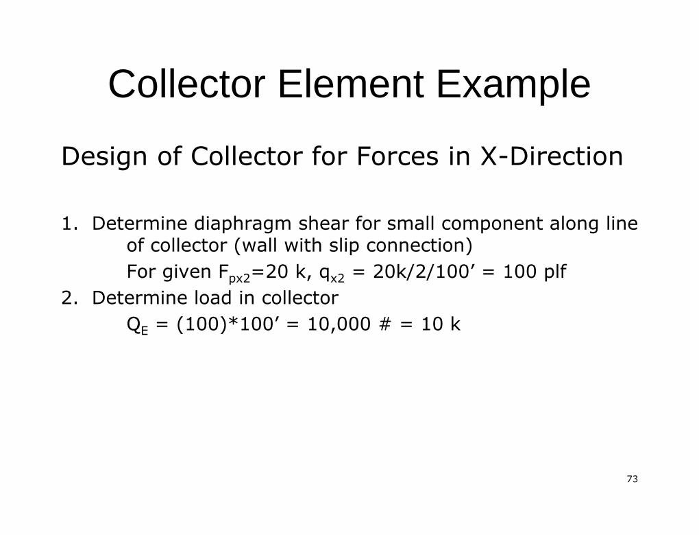
Design of Collector for Forces in XDesign of Collector for Forces in X--DirectionDirection
1. Determine diaphragm shear for small component along line1. Determine diaphragm shear for small component along lineof collector (wall with slip connection)of collector (wall with slip connection)For given FFor given Fpx2px2=20 k, q=20 k, qx2x2 = 20k/2/100= 20k/2/100’’ = 100= 100 plfplf
2. Determine load in collector2. Determine load in collectorQQEE = (100)*100= (100)*100’’ = 10,000 # = 10 k= 10,000 # = 10 k
7474
Collector Element ExampleCollector Element Example
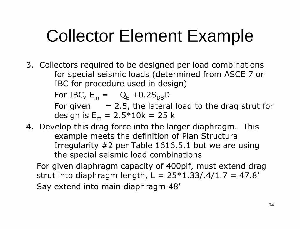
3. Collectors required to be designed per load combinations3. Collectors required to be designed per load combinationsfor special seismic loads (determined from ASCE 7 orfor special seismic loads (determined from ASCE 7 orIBC for procedure used in design)IBC for procedure used in design)For IBC,For IBC, EEmm == QQEE +0.2S+0.2SDSDSDDFor givenFor given = 2.5, the lateral load to the drag strut for= 2.5, the lateral load to the drag strut fordesign isdesign is EEmm = 2.5*10k = 25 k= 2.5*10k = 25 k
4. Develop this drag force into the larger diaphragm. This4. Develop this drag force into the larger diaphragm. Thisexample meets the definition of Plan Structuralexample meets the definition of Plan StructuralIrregularity #2 per Table 1616.5.1 but we are usingIrregularity #2 per Table 1616.5.1 but we are usingthe special seismic load combinationsthe special seismic load combinations
For given diaphragm capacity of 400plf, must extend dragFor given diaphragm capacity of 400plf, must extend dragstrut into diaphragm length, L = 25*1.33/.4/1.7 = 47.8strut into diaphragm length, L = 25*1.33/.4/1.7 = 47.8’’Say extend into main diaphragm 48Say extend into main diaphragm 48’’
7575
Collector Element ExampleCollector Element Example
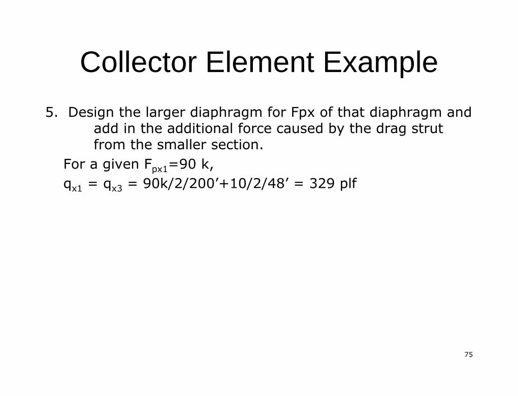
5. Design the larger diaphragm for5. Design the larger diaphragm for FpxFpx of that diaphragm andof that diaphragm andadd in the additional force caused by the drag strutadd in the additional force caused by the drag strutfrom the smaller section.from the smaller section.
For a given FFor a given Fpx1px1=90 k,=90 k,qqx1x1 = q= qx3x3 = 90k/2/200= 90k/2/200’’+10/2/48+10/2/48’’ = 329= 329 plfplf
7676
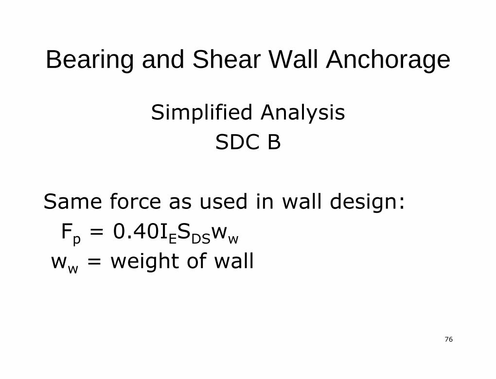
Bearing and Shear Wall AnchorageBearing and Shear Wall Anchorage
Simplified AnalysisSimplified AnalysisSDC BSDC B
Same force as used in wall design:Same force as used in wall design:FFpp = 0.40I= 0.40IEESSDSDSwwww
wwww = weight of wall= weight of wall

7777
Wall AnchorageWall Anchorage
Simplified Analysis SDC CSimplified Analysis SDC C
Must meet requirements of SDC B andMust meet requirements of SDC B and
For concrete or masonry wallsFor concrete or masonry wallssupported by flexible diaphragmsupported by flexible diaphragm
FFpp = 0.8S= 0.8SDSDSIIEEwwwwSupported by rigid diaphragmSupported by rigid diaphragm
7878
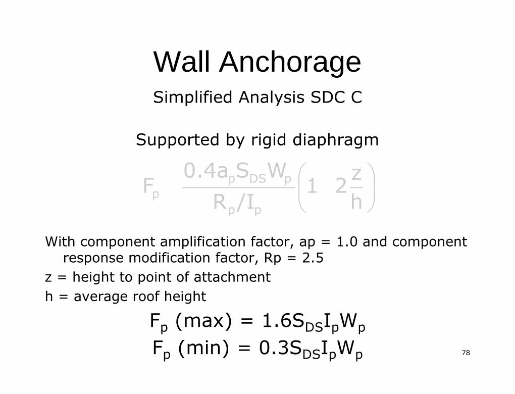
Wall AnchorageWall AnchorageSimplified Analysis SDC CSimplified Analysis SDC C
Supported by rigid diaphragmSupported by rigid diaphragm
With component amplification factor,With component amplification factor, apap = 1.0 and component= 1.0 and componentresponse modification factor,response modification factor, RpRp = 2.5= 2.5
z = height to point of attachmentz = height to point of attachmenth = average roof heighth = average roof height
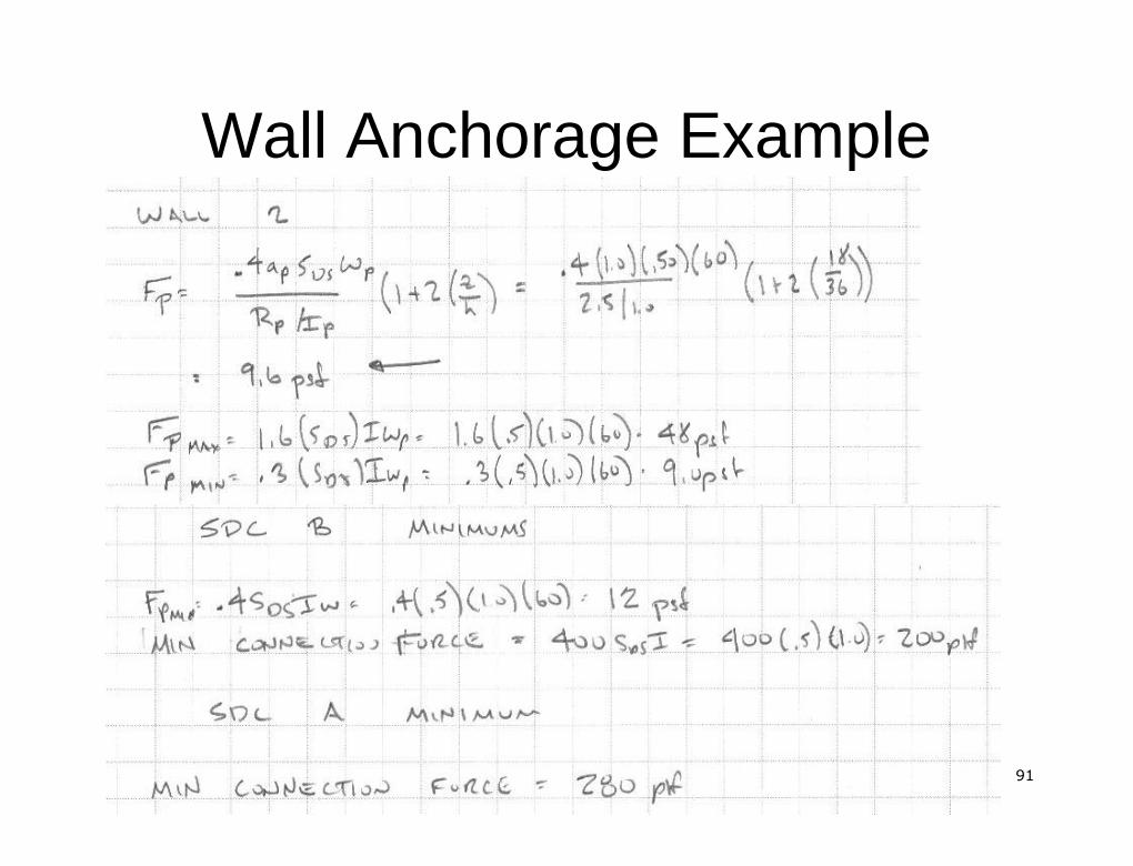
FFpp (max) = 1.6S(max) = 1.6SDSDSIIppWWppFFpp (min) = 0.3S(min) = 0.3SDSDSIIppWWpp
hz21/IR
WS0.4aFpp
pDSpp

7979
Wall AnchorageWall Anchorage
Simplified Analysis SDC CSimplified Analysis SDC CAdditional RequirementsAdditional Requirements
�� Continuous ties or struts must be provided toContinuous ties or struts must be provided totransfer wall anchorage forces into diaphragmtransfer wall anchorage forces into diaphragm
�� Metal deck cannot be used as tie or strutMetal deck cannot be used as tie or strutperpendicular to deck spanperpendicular to deck span
�� Wood sheathing cannot be used as tie or strutWood sheathing cannot be used as tie or strut�� Steel elements used for wall anchorage shallSteel elements used for wall anchorage shall
have the strength design forces (ultimate)have the strength design forces (ultimate)increased by 1.4increased by 1.4

8080
Wall AnchorageWall AnchorageSimplified Analysis SDC DSimplified Analysis SDC D
Must meet requirements of SDC C andMust meet requirements of SDC C andConcrete and masonry walls anchored toConcrete and masonry walls anchored toflexible diaphragms must alsoflexible diaphragms must also
�� Be designed for the forced induced by theBe designed for the forced induced by theeccentricity of wall anchorage connectionseccentricity of wall anchorage connectionsby elements that are not perpendicular toby elements that are not perpendicular tothe wallthe wall�� Be designed for additional forces collectedBe designed for additional forces collectedby pilasters in the wallby pilasters in the wall
8181
Wall AnchorageWall Anchorage
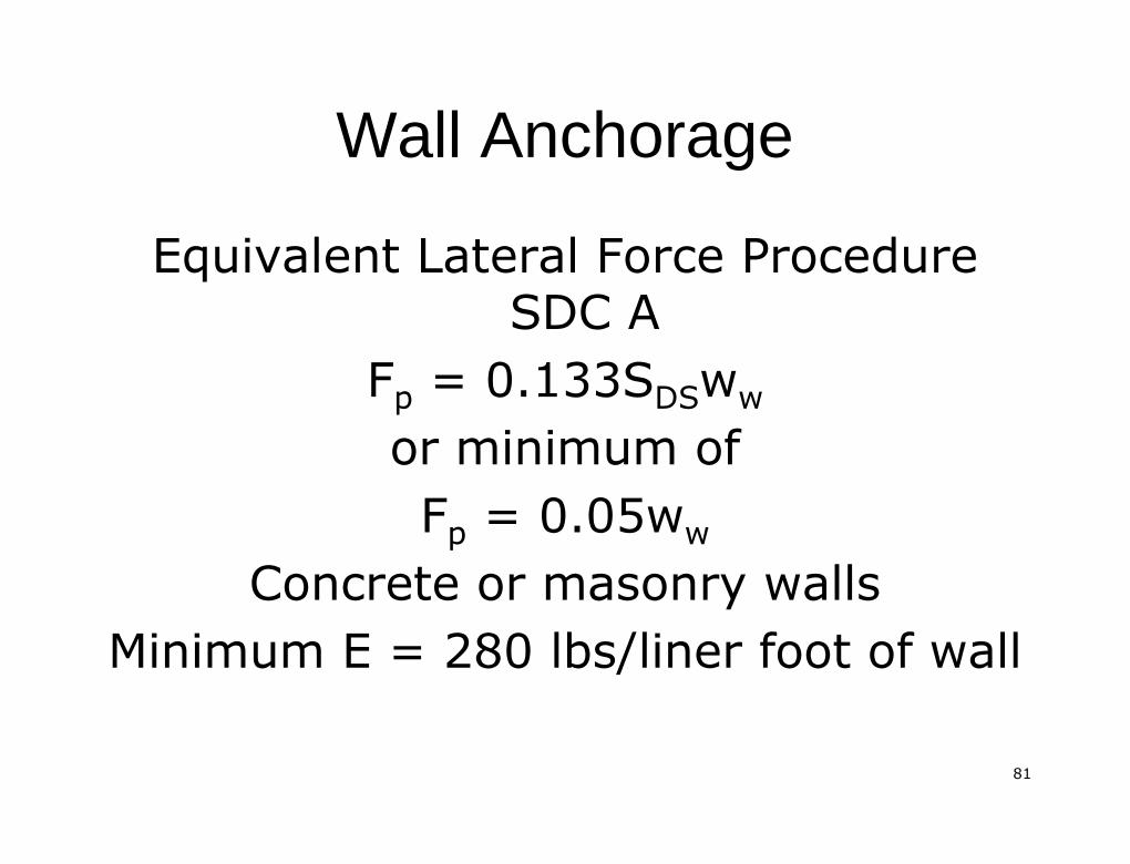
Equivalent Lateral Force ProcedureEquivalent Lateral Force ProcedureSDC ASDC A
FFpp = 0.133S= 0.133SDSDSwwwwor minimum ofor minimum ofFFpp = 0.05w= 0.05www
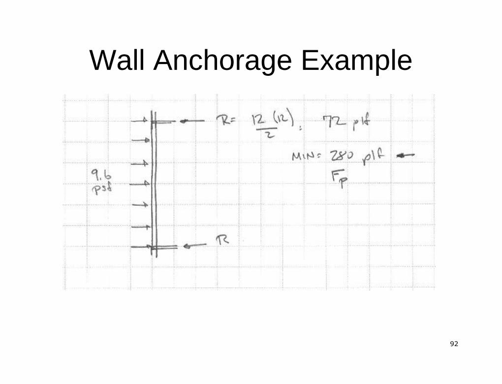
Concrete or masonry wallsConcrete or masonry wallsMinimum E = 280 lbs/liner foot of wallMinimum E = 280 lbs/liner foot of wall
8282
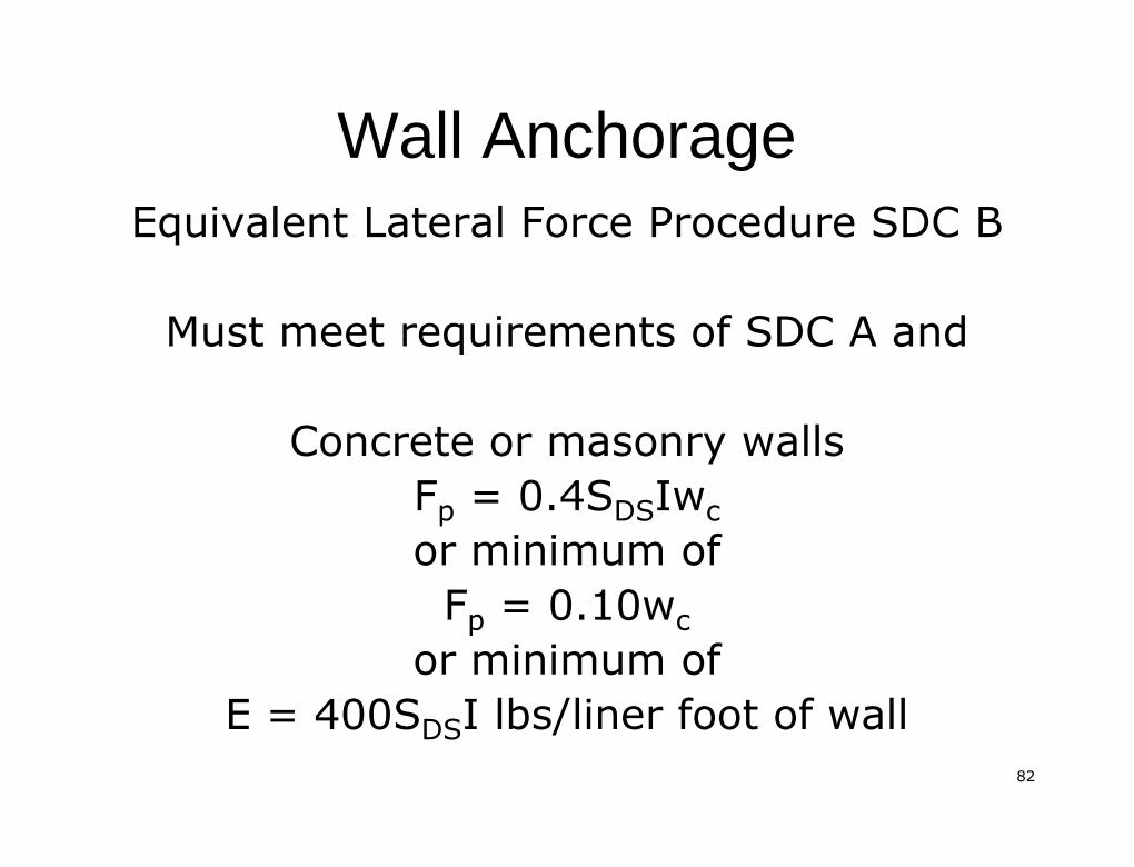
Wall AnchorageWall AnchorageEquivalent Lateral Force Procedure SDC BEquivalent Lateral Force Procedure SDC B
Must meet requirements of SDC A andMust meet requirements of SDC A and
Concrete or masonry wallsConcrete or masonry wallsFFpp = 0.4S= 0.4SDSDSIwIwccor minimum ofor minimum of
FFpp = 0.10w= 0.10wccor minimum ofor minimum of
E = 400SE = 400SDSDSI lbs/liner foot of wallI lbs/liner foot of wall
8383
Wall AnchorageWall Anchorage
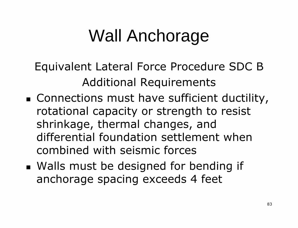
Equivalent Lateral Force Procedure SDC BEquivalent Lateral Force Procedure SDC BAdditional RequirementsAdditional Requirements
�� Connections must have sufficient ductility,Connections must have sufficient ductility,rotational capacity or strength to resistrotational capacity or strength to resistshrinkage, thermal changes, andshrinkage, thermal changes, anddifferential foundation settlement whendifferential foundation settlement whencombined with seismic forcescombined with seismic forces
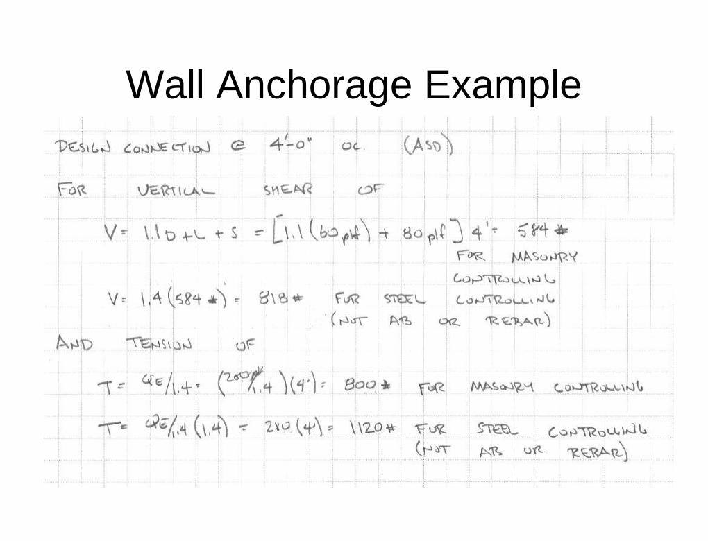
�� Walls must be designed for bending ifWalls must be designed for bending ifanchorage spacing exceeds 4 feetanchorage spacing exceeds 4 feet

8484
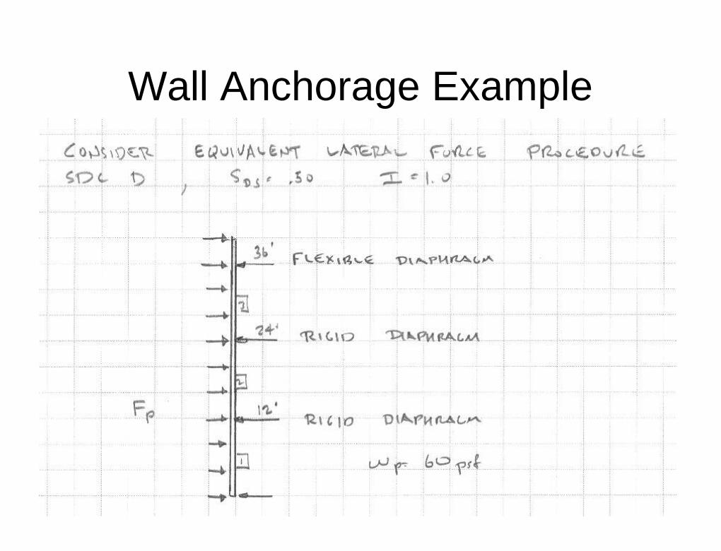
Wall AnchorageWall AnchorageEquivalent Lateral Force Procedure SDC CEquivalent Lateral Force Procedure SDC C
Must meet requirements of SDC B andMust meet requirements of SDC B andFor concrete or masonry walls supported by flexibleFor concrete or masonry walls supported by flexible
diaphragmdiaphragmFFpp = 0.8S= 0.8SDSDSIwIwpp
Supported by rigid diaphragmSupported by rigid diaphragm
FFpp (max) = 1.6S(max) = 1.6SDSDSIIppWWppFFpp (min) = 0.3S(min) = 0.3SDSDSIIppWWpp
Same equations as Simplified Analysis SDC C requirementSame equations as Simplified Analysis SDC C requirementexcept no 1.4 increase for anchor bolts and reinforcingexcept no 1.4 increase for anchor bolts and reinforcing
hz21/IR
WS0.4aFpp
pDSpp
8585
Wall AnchorageWall Anchorage
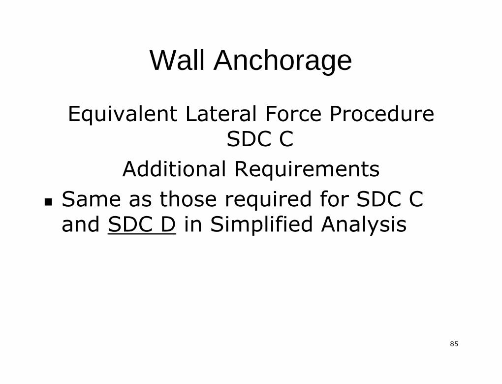
Equivalent Lateral Force ProcedureEquivalent Lateral Force ProcedureSDC CSDC C
Additional RequirementsAdditional Requirements�� Same as those required for SDC CSame as those required for SDC C
andand SDC DSDC D in Simplified Analysisin Simplified Analysis

8686
Wall AnchorageWall Anchorage
Equivalent Lateral Force ProcedureEquivalent Lateral Force ProcedureSDC D, E and FSDC D, E and F
No additional requirements regardingNo additional requirements regardingwall anchorage forceswall anchorage forces

8787
Wall Anchorage ExampleWall Anchorage Example
8888
Wall Anchorage ExampleWall Anchorage Example
8989
Wall Anchorage ExampleWall Anchorage Example
9090
Wall Anchorage ExampleWall Anchorage Example
9191
Wall Anchorage ExampleWall Anchorage Example
9292
Wall Anchorage ExampleWall Anchorage Example
9393
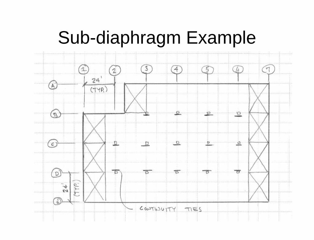
SubSub--diaphragmsdiaphragms
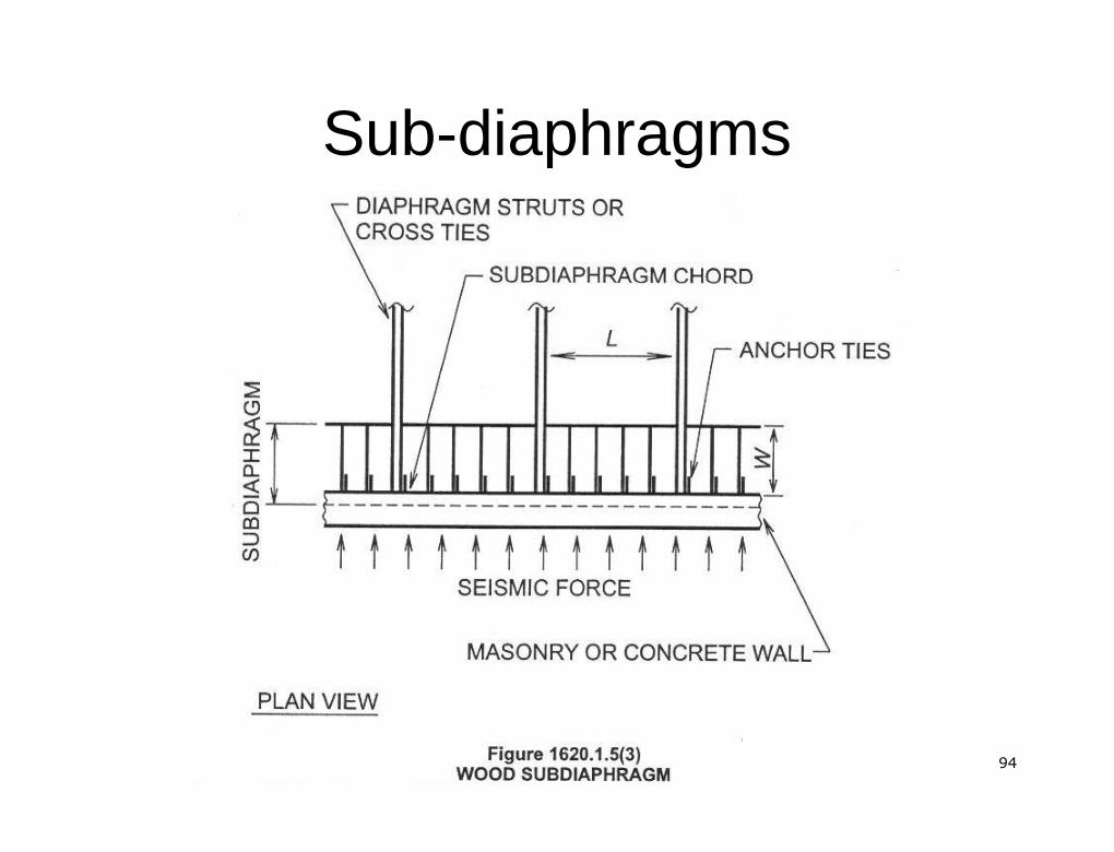
�� Continuous ties or struts must be providedContinuous ties or struts must be providedbetween main diaphragm chords to transfer wallbetween main diaphragm chords to transfer wallanchorage forces to the diaphragmanchorage forces to the diaphragm
�� Chords may be added to form subChords may be added to form sub--diaphragmsdiaphragmswith maximum length to width ration of 2.5/1with maximum length to width ration of 2.5/1(may be less for wood diaphragms)(may be less for wood diaphragms)
�� Wood diaphragm sheathing shall not beWood diaphragm sheathing shall not beconsidered effective as providing the ties orconsidered effective as providing the ties orstrutsstruts
�� In metal deck diaphragms, the metal deck shallIn metal deck diaphragms, the metal deck shallnot be considered effective as providing the tiesnot be considered effective as providing the tiesor struts in the direction perpendicular to theor struts in the direction perpendicular to thedeck spandeck span
9494
SubSub--diaphragmsdiaphragms
9595
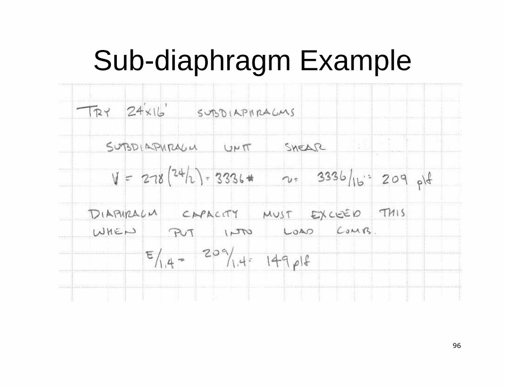
SubSub--diaphragm Examplediaphragm Example
9696
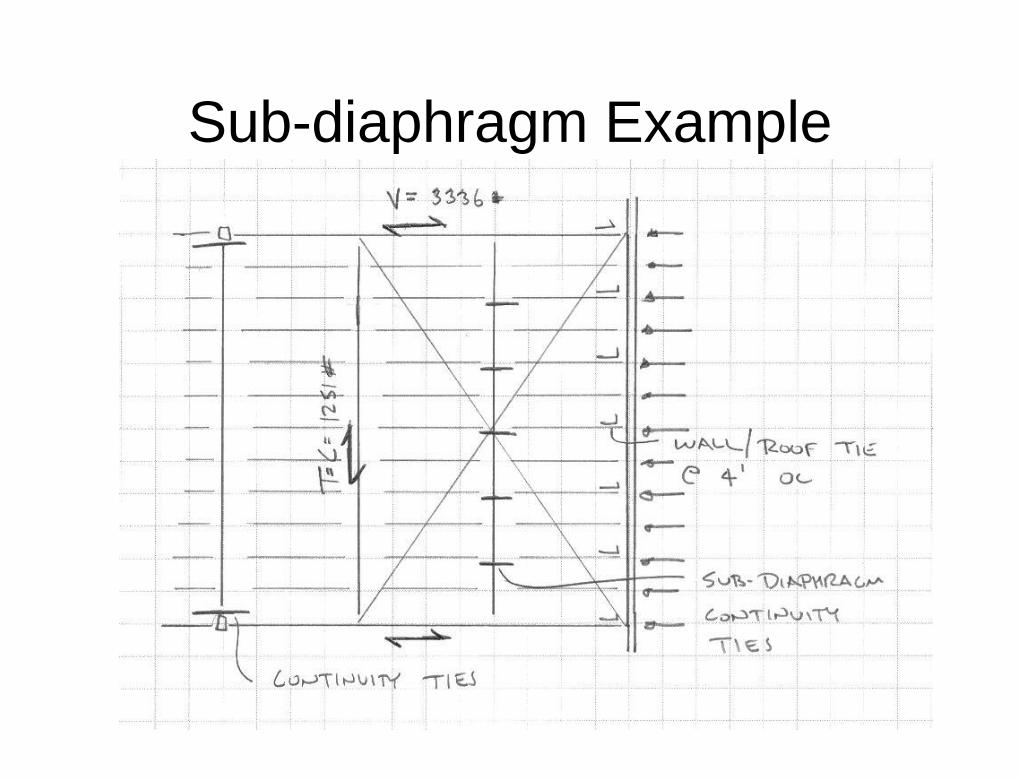
SubSub--diaphragm Examplediaphragm Example
9797
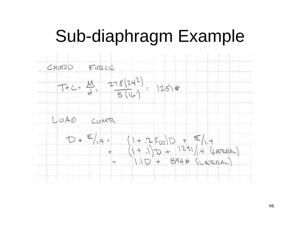
SubSub--diaphragm Examplediaphragm Example
9898
SubSub--diaphragm Examplediaphragm Example
9999
Seismic Design DiaphragmsSeismic Design Diaphragms
QUESTIONS?QUESTIONS?
