diana - signus.com · diana® sij distraction-interference-arthrodesis with neurovascular...
TRANSCRIPT

DIANA®
SIJ
Distraction-Interference-Arthrodesis with Neurovascular Anticipationnticipationnticipation
One screwOne screw
Gentle accessGentle access
Targeted placement
Not for distribution in the USA
P R O D U C T I N F O R M A T I O N

2
PRODUCT INFORMATION

3
Content
GeneralSacroiliac joint 4
Implant 5
Requirements for a successful procedure 7
Surgical training 8
Diagnostics and medical historyDiagnosis 9
Medical history and diagnostics 11
Diagnostic algorithm for surgical decision making 12
Pain provocation tests 13
Computed tomography 14
Preparing for the operationOrdering information 16
Checklist for the operation 17
Instruments 19
Checklist of additional instrumentation 20
Operation sequence with DIANAPreparing for the operation 21
Intraoperative imaging 24
Aligning the fluoroscope 25
Required images 26
Positioning 27
Surgical technique 29
Follow-up treatmentSample operative report 34
Postoperative treatment 35
Case study 36
DIANA

4
The sacroiliac joint SIJ is a load-bearing joint between the ilium and the sacrum. It is a true joint that has osseous subchondral surfaces, articular cartilage and ligamentous structure.
Although the SIJ makes only minor translational and rotational movements, over the course of a lifetime it can develop signs of wear. The reason for this is its position in the weight-bearing axis where it is exposed to large compression and shear forces.
During diagnosis, procedure, and postoperative care, fusion of the sacro-iliac joint consistently presents a challenge. Therapists should therefore be know ledgeable, experienced and thoroughly trained.
Sacroiliac joint
➔ Fusion of the SIJWithin the pelvis the mechanical axis is responsible for the position of the joint, which is specified by the converging axes of the lower extremities. The deep location of the anatomical structures make surgical access difficult.
Arthrodesis of the sacroiliac joint should only be considered if conservative therapies are not effective, pronounced pain persists and all contraindica-tions have been excluded.1
Responsible use of the DIANA method is particular important. SIGNUS therefore offers detailed professional training that covers all aspects of the procedure from determining indications to assessing surgical outcomes. SIGNUS also supports the new user throughout the learning process.
1 Lorio MP, Rashbaum R.: ISASS policy statement – minimally invasive sacroiliac joint fusion. (Int J Spine Surg. 2014 Dec 1;8. Updated March 15, 2015)
PRODUCT INFORMATION

5
The implant design has the following characteristics:
■ Hollow interference screw made of titanium Ti6Al4V
■ Multifunctional thread profile has proximal shoulder to resist subsidence
■ Multifunctional, conical section is self-tapping and distracting
■ Large central cavity for bone graft
■ Fenestrations for bony union
■ Easy to revise
Implant
Distally self-tapping
Fenestration transports bone into the implant interior
Anti-subsidence shoulder
Conical taper
DIANA

6
Distraction Interference ArthrodesisIn an atraumatic and low-risk procedure, the DIANA method anchors an interference implant via a posterior access distally in the iliac bone. The proximal and central part of the implant is located in the extra-articular recess without affecting the actual articular surfaces.
The surgical access to the recess and the path of the instruments and implant follow the iliac diaphysis and thus the weight-bearing axis of the pelvis. The intraoperative radiographic images are adjusted taking this axis into consid-eration. The transition of the bony segments of S1 and S2 thus forms the entry point for the guide wire and the instruments, the trajectory of which travels from this point towards the hip joint.
The joint space is then distracted during the procedure, relieving stress on the joint cartilage as well as capsular neural structures and those neural struc-tures immediately anterior to the joint. It is thus possible to approximate the original state of the pelvic girdle using ligamentotaxis. The entire procedure is carried out within a safe access zone with no weakening of the musculature or the bony structures. Retraction and revision are still entirely possible.
Note
Permanent fusion is achieved by thorough preparation, targeted debridement of the iliac and sacral cortical bone in the recess, and apposition of bone material in both the extra-articular recess and in the implant.
* 3D
exa
mpl
e, n
ot s
uita
ble
for
anat
omic
al t
each
ing
purp
oses
.
Implant
DIANA method*
Trajectory of the guide wire.
PRODUCT INFORMATION
7
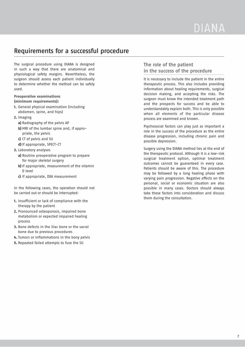
The surgical procedure using DIANA is designed in such a way that there are anatomical and physiological safety margins. Nevertheless, the surgeon should assess each patient individually to determine whether the method can be safely used.
Preoperative examinations (minimum requirements):1. General physical examination (including
abdomen, spine, and hips)2. Imaging
a) Radiography of the pelvis APb) MRI of the lumbar spine and, if appro-
priate, the pelvisc) CT of pelvis and SIJd) If appropriate, SPECT-CT
3. Laboratory analysesa) Routine preoperative program to prepare
for major skeletal surgeryb) If appropriate, measurement of the vitamin
D levelc) If appropriate, DXA measurement
In the following cases, the operation should not be carried out or should be interrupted:
1. Insufficient or lack of compliance with the therapy by the patient
2. Pronounced osteoporosis, impaired bone metabolism or expected impaired healing process
3. Bone defects in the iliac bone or the sacral bone due to previous procedures
4. Tumors or inflammations in the bony pelvis5. Repeated failed attempts to fuse the SIJ
Requirements for a successful procedure
The role of the patient in the success of the procedure
It is necessary to include the patient in the entire therapeutic process. This also includes providing information about healing requirements, surgical decision making, and accepting the risks. The surgeon must know the intended treatment path and the prospects for success and be able to understandably explain both. This is only possible when all elements of the particular disease process are examined and known.
Psychosocial factors can play just as important a role in the success of the procedure as the entire disease progression, including chronic pain and possible depression.
Surgery using the DIANA method lies at the end of the therapeutic protocol. Although it is a low-risk surgical treatment option, optimal treatment outcomes cannot be guaranteed in every case. Patients should be aware of this. The procedure may be followed by a long healing phase with varying pain progression. Negative effects on the personal, social or economic situation are also possible in many cases. Doctors should always take these factors into consideration and discuss them during the consultation.
DIANA

8
Theory
SIGNUS is here for you!
We will be by your side while you learn the DIANA method until you and your team feel comfortable with the procedure.
At our regular training events, you first learn the theoretical foundation of the DIANA procedure – from the biomechanics of the SIJ, to determining the indication and conservative treatment options, to assessment of the surgical results. Then, you will learn the practical application of DIANA.
For your first DIANA operations, we provide a tutor to observe and assist who is completely familiar with the DIANA procedure and will give you valuable tips and tricks throughout the whole process. In addition our DIANA support staff will also train your surgical personnel and accompanies them with their subsequent cases until they are comfortable with the procedure.
Of course, your tutor and the DIANA support staff are available to address any questions regarding indications, surgical technique and assessment of surgical results. There is also the opportunity to observe a DIANA procedure at one of our reference centers.
Surgical training
PRODUCT INFORMATION

9
Before planning the procedure the sacroiliac joint must be unambiguously identified as the source of the pain.
Because the SIJ is part of an anatomical complex made up of the spine and lower extremities, the doctor must consider other possible causes of pain in adjacent structures. As well as the SIJ, the spine and/or the hip joints are often also affected. It is therefore necessary to perform comprehensive clinical evaluation and diagnostics to identify the source of the pain. Due to mechanical or radicular symptoms, the SIJ can also mimic conditions in the lumbar spine and/or the hip joints. The reverse is also true.1
Treatment of pathological findings may therefore include one or multiple operations.
The neurovascular structures surrounding the SIJ are fundamentally involved in the disease process in the joint. The surgeon and his or her team should be aware of the complex interrelationships and make use of all necessary non-invasive and invasive diagnostics and therapeutic options before considering surgery.
Diagnosis
Typical seated position with SIJ pain (pain on the right side).
1 Lorio MP, Rashbaum R.: ISASS policy statement - minimally invasive sacroiliac joint fusion. (Int J Spine Surg. 2014 Dec 1;8. Updated March 15, 2015)
DIANA

10
Last name: First name:
Date of birth: MM DD YYYY Date: MM DD YYYY
1. Sex: X Male X Female
Weight: Number kg
Height: Number cm
BMI: Number
2. Affected side (clinically more painful): X right X left X bilateral
3. Symptoms have been present since: Month, year
4. Previous spinal/SIJ surgery; what: Name
when: Month, year
Are there pedicle screws in S1? X right X left X bilateral
5. Previous conservative therapy:
X Denervation [RF] [cryo]
X Orthosis
X Physiotherapy
X Other: Name
6. PSIS diagnostics:
X Pain diagram: X typical X atypical
X Patrick test: X right X left X bilateral X no
X Tenderness to palpation over SIJ: X right X left X bilateral X no
X Sitting intolerance: X right X left X bilateral X no
7. Pain medication (drug/dosage /duration):
NSAIDs: Name
Opioids: Name
Opiates: Name
8. Smoker X yes X no
How long (years): Number
Number of cigarettes/day: Number
Medical history and diagnostics
PRODUCT INFORMATION

11
9. What is the patient’s current working situation?
X Not employed
X Current retirement application process
X Early retirement
X Retirement
X Employed, please specify: Text
10. Last practiced employment/profession: Name
Specify the work activities: Text
X Not physically active
X Light physical activity
X Heavy physical activity
11. What is the problem attributed to?
X Accident
X Pregnancy
X Previous OP
X Rheumatism
X Degeneration
X Not known
X Other cause, please specify: Text
12. Comments
Name
Name
Medical history and diagnostics
A print version of this document can be found in the download area of our homepage www.signus.com.
DIANA

12
SIJ: Diagnostic algorithm for surgical decision making
To be completed by the patient:
■ Pain diagram
■ Pain scale VAS
Non-invasive ■ Corset
■ Manipulative therapy / osteopathy
■ Oral analgesics
■ Ultrasound
■ Palpation, long posterior ligament at the attachment of the posterior superior iliac spine, standing
■ Pain provocation test, e.g., Patrick test (FABER test)
■ Thorough examination of the lumbar spine and the hip joints
Invasive ■ Joint space injection
■ Intra-articular injection
■ RF / cryodenervation
■ Prolotherapy
■ Radiograph of the pelvis overview
■ CT of the pelvis
■ If appropriate, SPECT-CT
■ If appropriate, MRI
■ Diagnostic injections (CA), intra-articular / joint space
Conservative therapy
Therapeutic success
Yes
If appropriate, repeat
Surgery
No
No
Medical history Clinical examination Instrument-baseddiagnostics
PRODUCT INFORMATION

13
Patrick test (FABER test)
The patient is placed in a supine position. One leg is flexed, abducted, and rotated outwards (FABER: Flexion, Abduction, External Rotation) and the ankle is placed on the contralateral knee. The therapist stabilizes the contra-lateral iliac wing to the anterior superior iliac spine (ASIS) and then exerts a slight overpressure on the knee in the abducted position. 1
Pain provocation tests
1
3
4
5
6
2Compression testThe patient is placed in a lateral position. The therapist exerts vertical downward pressure with both hands on the upper iliac crest. The posterior ligaments of the SIJ should be stretched by this test and be compressed anteriorly. 2
Distraction test (gapping test)
The patient is placed in a supine position. The therapist presses with his or her hands both anterior superior iliac spines (ASIS) in a posterolateral direction. The anterior ligaments of the SIJ should be stretched by this test and be posteriorly compressed. 3
Thigh thrust (posterior shear, P4 test or posterior pelvic pain provocation test)
The patient is placed in a supine position. The therapist holds the opposite leg in 90-degree hip joint flexion and stabilizes the sacrum with the other hand (to act as a hypomochlion). The vertical femur produces a shearing force in the SIJ. 4
Sacral thrustThe patient is placed in a prone position. The therapist applies a vertical, pulse-like anteriorly directed pressure over the sacrum. 5
Gaenslen’s test (pelvic torsion)
The patient is placed in a supine position with the affected leg hanging over the edge of the examination bench. The other leg is flexed to the end of the range of movement at the hip and is stabilized by the therapist. Applying overpressure to the extended leg achieves rotation of the ilium relative to the sacrum and ilium. 6
DIANA

14
CT imaging for pathological evaluation of the sacroiliac joint
Basic images
To exclude any pathologies that are located higher and that are only projecting onto the SIJ, images in the axial plane in the bone window from L4 to the femoral heads should be taken with a maximum slice thickness of maximal 1.5 to 2.0 mm.
SIGNUS can prepare reconstructions for you using your images. Please send the images directly to your DIANA tutor. Ensure that all patient data are anonymized before you send the images to SIGNUS.
Imaging and assessing the sacroiliac joint by CT requires time and experience. It presents a new challenge to many radiologists and spinal surgeons.
Computed tomography
PRODUCT INFORMATION

15
A
Diagnosis of pathological changes of the sacroilial joint on the CT
As a link between the lumbar spine and the hip joint, the sacroiliac joint (SIJ) is constantly subject to high compressive and shear forces as well as high levels of cyclic loading. Many authors believe that this combi-nation of stresses results in painful osteoarthritis.Persistent complaints can, however, also be caused by dysplastic, infl ammatory, post-traumatic, post-partum or post-operative causes. Arthrodesis of the SIJ is sometimes recommended when nonoperative methods fail to address symptoms.
Though multiple methods of SIJ fusion have been proposed no method has received general accept-ance. In addition, indications have been unclear and poorly correlated with imaging changes. The introduc-tion of ‘Distraction Interference Arthrodesis’ (DIANA®, by SIGNUS-Medizintechnik, Germany), a promising new method, has highlighted the need for an improved method of imaging and defi nition of painful changes of the SIJ.
1. CT slice thickness: 1.5 – 2.0 mm; bone window (W 3200, L1000, Filter D)
2. Axial slices from lumbar spine segment 4 down to the upper edge of the greater sciatic notch
3. Reconstruction of additional sectional planes at the height of the S1 neural foramen where it is projected at one half the distance from the spinal canal to the anterior sacral margin.
4. In addition to simple axial, sagittal and coronal reconstructions, recon-struction levels are provided parallel or perpendicular to the angle of the oblique SIJ for improved depiction:
● parasagittal ● paracoronal ● paraxial ● sacral-coronal
V. Fuchs, AMEOS Klinikum, Halberstadt
J.G. Stark, Backpain Clinic, Minneapolis (USA)
Axial slicesshould additionally include the spinal segments L4 and L5 for diff er-ential diagnosis
Sagittal slices (here: right)show, in addition to the dorsal recess of the SIJ, the facet-like inter-locking of the sacral bone and the iliac bone
Coronal slices depict the caudal section of the SIJ together with facet joints L4/5 and L5/S1; good depiction of the recess size right/left; The S1 root is fully traceable from the spinal canal to the SIJ
Parasagittal slices (here: right)run as parallel as possible to the SIJ and show the interlocking from the iliac bone to the sacral bone
Paracoronal slices (here: right)show a true cross-section through the SIJ as well as its dorsal recess; the course of nerve root L5 and S1 along the ventrocaudal section of the SIJ can often be recognized, as well as causes of possible irrita-tion (such as osteophytes) at this location
Paraxial slices depict the anterior and posterior neural foramina of the sacral bone in one level and in particular show their proximity of the dorsal recess
Sacral coronal slices show the transverse processes of the sacral bone and the upper as well as lower sections of the recess instabilities in the SIJ are refl ected as incongruities in the form of a intraarticular vacuum phenomenon
6. Orientation of paraxial or sacral coronal reconstructions parallel to the base or cover plate of S1/S2 or perpendicular to this green line
Normal fi nding Osteoarthritis
5. Planning of parasag-ittal or paracoronal sectional planes parallel or perpendic-ular to the actual joint (green line), not to the recess (red line)
✓ ✓
S i S i
S
i
i S
ii
S1
S1
S1
A suggested protocol for
Diagnosis of pathological changes of the sacroiliac joint in CT
Dr. Volker Fuchs M.D., AMEOS Hospital, Halberstadt (Germany)
Computed tomography
DIANA

16
After careful preparation of the fusion surfaces, the fusion is completed by placement of the graft material. SIGNUS recommends using autograft and/or allograft.
Caution
Consider homologous cancellous bone when ordering!
Implants
After careful preparation of the fusion surfaces, the fusion is completed by placement of the graft material. SIGNUS recommends using autograft and/
Art. No. Description Ø (mm) Length (mm)
SJ1312 DIANA IF Implant 13/12 30
SJ1514 DIANA IF Implant 15/14 30
SJ1716 DIANA IF Implant 17/16 30
SJ1918 DIANA IF Implant 19/18 30
SJ2119 Revision implant (only on request)
Ordering information
PRODUCT INFORMATION

17
Checklist for the operation
Has everything been prepared for
the procedure?
✔ DIANA instrumentation (one set per patient) ✔ Work through the checklist
✔ Bone graft material: about 30cc per patient ✔ Implant: one set per patient
✔ Is SIGNUS surgery support required? ✔ Is prior instruction required?
Operating tableTo ensure reliable intraoperative radiological imaging the operating table should be reviewed with respect to the following criteria:
■ How much metal is in the operating table? Where is it?
■ How far can the operating table move at the head and foot ends?
■ Where is the support column?
■ Is the table made of carbon fiber?
■ Is the table partly or completely made of carbon fiber?
Caution
Be aware of any metal rails or supports between the carbon fiber sections!
Positioning aidsTo ensure correct positioning of the patient, ensure that the following positioning aids are available:
■ Spinal frame
■ VAC cushions 60 × 80cm
■ Thoracic cushions
■ Leg/foot bolster
■ Knee gel cushions
■ Various gel cushions
FluoroscopeIt is important to check how far the fluoroscope can be rotated around the operating table. It is best if it can be rotated at least 30º to 35º from vertical.
MicroscopeFor optimal visualization of the recess it is essential to use a microscope during the dissection.
Correct patient positioning on a standard operating table with metal braces.
Correct patient positioning on a carbon fiber table.
DIANA

18
The instruments are arranged in the order in which they will be used in two sterilization trays.
Tray #1 contains the instruments for dissection and preparation for fusion.
Instruments
The distraction achieved with the helio determines the diameter of the subsequent instruments which are color-coded by size and grouped in Tray #2 by color.
1
3
2
4
5
6
7
8
9
Fig. Art. No. Description
1 SH0038 Graft impactor2 SH0042 Pre-Cutter3 P022AX Bone curette, straight4 P019AX Bone curette, straight5 SH0037 Bone curette, small (300 mm)6 SH0021 Drill Guide7 SH0022 Guide Pin, blunt 2.4mm8 SH0023 Guide Pin, threaded9 SH0011 Helio (recess screw) 13/12 mm
SH0012 Helio (recess screw) 15/14 mmSH0013 Helio (recess screw) 17/16 mmSH0014 Helio (recess screw) 19/18 mm
10 T001AQ Mallet11 SH0030 T-Handle fixed; 1/4“
Fig. Art. No. Description
12 SH0020 Trajector Inserter13 SH0019 Trajector Sleeve14 SH0015 Trajector 13 mm
SH0016 Trajector 15 mmSH0017 Trajector 17 mmSH0018 Trajector 19 mm
15 SH0024 Sliding Hammer16 SH0010 Depth stop17 SH0006 Reamer 13 mm
SH0007 Reamer 15 mmSH0008 Reamer 17 mmSH0009 Reamer 19 mm
18 SH0001 Inserter 13 mmSH0002 Inserter 15 mmSH0003 Inserter 17 mmSH0004 Inserter 19 mm
Optional (no image)
SH0033 HarvesterSH0033-2 Harvester, shaftSH0033-3 Protection sleeveSH0033-1 Reamer for harvesterSH0043 Bone biopsy trephine
PRODUCT INFORMATION

19
Instruments
15
18
17
16
10
13
14
11
12
DIANA

20
Checklist of additional instrumentation
Correct preparation of the required instruments.
Tip
Instrument the DIANA implant directly from the special trays!
In addition to the DIANA instrumentation, only a few additional instru-ments that are found in every operating theater as standard instruments are required for surgery using the DIANA method. To efficiently set up the prepa-ration and reprocessing of the instruments, SIGNUS recommends assembling the following equipment and materials:
General preparation ✔ Sterile drape, gown, sterile gloves ✔ Fluoroscope cover ✔ Microscope cover ✔ Sterile light handles or light handle covers ✔ Suction ✔ 4x 5ml syringes ✔ Sterile pen and ruler ✔ Fusion material (homologous bone graft) ✔ Thick felt pen (Edding) and long non-sterile K wire for planning incision
Basic instrumentation ✔ Skin prep set – dressing forceps ✔ 2 metal basins ✔ Scalpel handle, short (skin) ✔ Scalpel handle, long (15FIG) ✔ 2 cervical retractor systems e.g. CERCCESS™ or similar ✔ 2 Langenbeck retractors ✔ 2 needle holders ✔ 2 surgical tweezers ✔ 2 anatomical tweezers ✔ Dissection scissors ✔ Suture scissors ✔ Cobb elevator, large (very important!) ✔ Dissector ✔ 2 straight rongeurs, sizes 3 and 4 ✔ Possibly 1 to 2 different bone curettes(not essential) ✔ Luer, large ✔ Luer, medium
Additional instrumentation ✔ Battery-operated drill with Jacobs chuck or quick-release chuck ✔ High-speed drill (rose-head attachment 4–6mm) ✔ Bipolar bayonet-shaped forceps ✔ Monopolar with long attachment ✔ Instruments to remove S1 screws (if necessary)
Optional: ✔ Hollow drill to remove iliac crest bone graft (diameter up to approx. 0.7mm). This drill is also available directly from SIGNUS on request.
The content of this checklist is not included in the DIANA tray.
PRODUCT INFORMATION

21
Nurse
Assistant
Surgeon
Prerequisites for successful implantation with DIANA are an adequately equipped operating theater, correct positioning of the patient, and clear and precise radiographical imaging. The entire surgery time (incision / suture) is about 90–120 minutes. If the personnel is already experienced in positioning the fluoroscope, this shortens the surgery time accordingly.
Preparing for the operation
Configuration of the operating theater for surgery on the patient’s right SIJ using the DIANA method.
➔ Surgery positionsThe DIANA method requires a radiolucent operating table, a fluoroscope, and a microscope. The figure shows the operating room layout for a patient whose right sacroiliac joint will be treated. The surgeon stands on the opposite side to that being treated.
DIANA

22
Preparing for the operation
1 Layout
a) Operating table with no obstacles (carbon fiber table)
■ The patient is placed in a standard delordosed prone position using appropriate positioning aids (see page 17).
b) Standard operating table
■ The patient is placed in a standard delordosed prone position using appropriate positioning aids (see page 17).
■ A VAC cushion ensures the position is optimized and that the patient is stable.
■ The patient must be positioned with the non-operative side far over to the edge of the operating table. This allows oblique radiographic imaging.
b1) Position of the metal braces
■ Depending on the position of the column, the patient has to be positioned very far towards the foot or head end.
Caution
The pelvis must not be positioned at the level of the column because radiographic imaging is otherwise not possible!
Note
For table tops made completely of carbon fiber, points b) and b1) do not have to be considered.
c) Radiographic guidance
■ AP
■ Oblique (for checking the positioning)
■ Lateral
d) Fixation
■ Following this, the anesthetist can optimally secure the position and organize the placement of any other necessary aids.
PRODUCT INFORMATION

23
Is everything ready for the operation?✔ Implants✔ Graft material✔ Radiolucent operating table✔ Fluoroscope, freely moveable
✔ Microscope✔ Positioning cushions✔ DIANA instrumentation✔ Additional instrumentation (see p. 20)
2 Patient positioning
Proper positioning of the patient is imperative for both access and intraoper-ative imaging. For this purpose, the patient is positioned on the radiolucent operating table in a prone position.
Important: The patient must be placed in a stable position to avoid too much lordosis in the lumbar spine because this makes the visualization and exposure of the recess difficult. The use of a vacuum cushion around the lumbosacral transition with a delordosed position has proven useful. The landmarks for the incision are located using radiographic imaging and a wire and are marked on the skin: the midline and the upper edge of the sacrum form almost the center of the skin incision. From this point the incision is made 3cm cranially and 2cm caudally. The fenestration of the surgical drape must extend at least 8cm laterally from the midline to the point at which the posterior superior iliac spine is at its widest and is subcutaneously prominent.
Instruments and materials that are not included in the DIANA tray can be prepared using the checklist (see page 20).
Preparing for the operation
Iliac crestIliac crest
Sacroiliac joint
L5
S1
S2
S3
S4
K wire
Inci
sion
Marks and incision site for an operation using the DIANA method on the right side of the patient.
3 Fluoroscopic positioning
■ The fluoroscope is located on the correct side. ✔
■ The patient data have been recorded. ✔
■ The spine is selected using pulsed fluoroscopy. ✔
■ The position is correct. ✔
The operation can start.
DIANA

24
Anatomy of the pelvis
■ The patient is placed in a prone position.
■ The legs are extended normally, the knees are cushioned, and a foot bolster is positioned.
■ The SIJ is displayed with recess, the upper edge of the sacrum, acetabulum, and femoral head (visible in all three projections).
Fluoroscopy technique
■ The C-arm and the monitor cart must always be placed on the side of the patient that is being operated on.
■ After aligning the C-arm relative to the operating table, it is locked into its working position and its location is marked on the floor using tape. The operating field is then disinfected and the sterile drape is placed over the patient and the C-arm. The automatic dose rate control (ADR) for the C-arm is switched off by activating the stop button.
■ All other fluoroscopic images should be done using pulsed fluoroscopic mode (if possible depending on the device).
■ The C-arm receiver system must be located as close as possible to the body area being examined for all fluoroscopic images.
Documentation and archiving
■ Total fluoroscopy duration and dose area product.
■ Names of radiographer or expert physician carrying out the fluoroscopy.
■ The archiving is done using the DICOM standard on appropriate data media for a period of at least ten years.
Intraoperative imaging
Spina iliaca posterior superior
Vertebra lumbalis V (L5) Os ilium
Spina iliaca anterior inferior
Symphysis
Acetabulum
Sacroiliac joint
PRODUCT INFORMATION

25
X
Y
X
Setting up the fluoroscope
1 Typical lateral view: Representation of the sciatic foramina and femoral heads.
2 Basic adjustment and positioning of the fluoroscope.
The fluoroscope is aligned before the operation or before the first incision by rotating and adjusting the height of the C-arm. All required views can then be obtained from this position.
➔ Aligning the fluoroscopeAs soon as the C-arm has been brought into the required starting position for the DIANA method, all necessary views can be prepared. For this purpose, the C-arm must be at a 90° angle to the patient. 2 For better orientation, rotate the lateral view by 90 degrees. 1 The C-arm is now positioned so that the two sciatic foramina are aligned in the lateral view. Double projection would otherwise distort the direction of the trajectory.
Adjusting the fluoroscope in case of double projection of the sciatic notches (near side and contralateral landmarks):
X = Correction of an anterior / posterior shift (tilt the table).
Y = Correction of a superior / inferior shift (adjust the C-arm).
Y
X
DIANA

26
For implantation of the DIANA system, radiographic views in three planes are required: AP, oblique, and lateral. All these views can be obtained from the previously defined position of the fluoroscope by rotating the C-arm.
➔ APFor the AP view of the affected SIJ, the carriage must be pulled back and the ilium, lateral part of the sacrum, and the acetabulum with the acetabular dome are imaged.
Required images
➔ lateralThe C-arm is pivoted around for the lateral view and positioned close to the patient. For intraop-erative lateral positioning, ensure that the large sterile drape is attached while rotating the arm. The drape should be fixed to the opposite side of the C-arm at the height of the operating table.
➔ obliqueTo obtain the oblique view, the C-arm is rotated in 10-degree steps from 10 to 30 degrees to the midline so that the X-ray beam is directed downwards through the extra-articular space of the SIJ. The final oblique angle is usually less than that of a true Judet view; this is de facto rather an AP view of the recess.
30°
20°10°
PRODUCT INFORMATION

27
Arcuate line
Sciatic notch, here shown congruent.
The red mark indicates the base of the recess.
The entry point for the guide wire is located within the area marked.
The yellow lines indicate the arcuate line (left) and the sciatic notch (right) respectively.
Sacrum
Ilium
Acetabulum
Femoral head
Sacrum
Base of the recess (entry point for the guide wire)
SIJ (horizontal joint space)
Sacrum
Arcuate line
Sciatic notch
Femoral heads
Due to its three-dimensional alignment, the SIJ can only ever be viewed in parts in the radiograph.
The yellow lines indicate the arcuate line (left) and the sciatic notch (right) respectively.
The light blue line shows the entry point of the guide wire at the height of S1/2 of the intervertebral disc.
Positioning
AP
oblique 25°– 35°
lateral
DIANA

28
Iliac crestIliac crest
Sacroiliac joint
L5
S1
S2
S3
S4
K wire
Inci
sion
■ First, ensure that all instrumentation (including general instruments), the fluoroscope and the consumables are prepared.
■ Radiographic and CT images should be used to confirm the indications and to check for adequate bone quality, post-traumatic bone defor-mities or special anatomical features as part of the preoperative surgical planning because the size, shape, and alignment of the recess are extremely variable.
■ Any implants such as iliosacral screws or S1 pedicle screws must be removed if they are blocking the access routes for the instrumentation. As part of the preoperative planning, it must be ensured that appro-priate instruments for removal of any metal components are available.
Marks and incision site for an operation using the DIANA method on the right side of the patient.
The recess located behind the SIJ is divided by the S2 transverse process into a larger upper (between S1 and S2) and a smaller lower (between S2 and S3) preformed spaces. The interosseous ligaments, which are resected during the dissection, are located here.
Anatomical landmarks for the operation
Surgical technique
Posterior sacroiliac ligaments
Anterior sacro-iliac ligaments
Sacroiliac joint
Interosseous ligaments Lower (smaller) recess
Upper (larger) recess
Axial section Coronal section
PRODUCT INFORMATION

29
1 = Upper recess
2 = Lower recess
2
1
1 Access and dissection of the recess
■ First, the height of the skin incision must be determined. ■ An incision about 5cm long is made down to the thoracolumbar fascia. ■ A sharp retractor that can curve through a joint is then used. ■ The dissection is then made epifascially in a lateral direction to the posterior superior iliac spine (PSIS) on the affected side.
■ After identifying the posterior superior iliac spine (PSIS), a fascial incision offset about 1.5cm towards the midline is made. This runs about 1.5cm caudally to the skin incision.
■ A second bendable retractor is inserted after blunt dissection of the musculature to the posterior sacroiliac ligaments.
■ Access to the recess is done by preparing along the ilium. This is done with a Cobb elevator and identification of the upper recess using the trampoline effect.
■ With a scalpel enter the recess at an angle of about 45 degrees in a lateral direction to the ilium. The posterior sacroiliac ligaments are resected via the larger upper recess; from here the entry is made with the bone curette.
■ AP and oblique radiographs are used to confirm the correct position. ■ These steps are carried out using the microscope. ■ Using the large straight bone curette from SIGNUS, the medial iliac wall is dissected along the entire extent of the recess from cranial to caudal to the recess base. This process requires extreme care and must be done beneath the fascial attachment. During the process the attachments of the longissimus muscle must not be damaged or detached. For this purpose, the bone curette is moved back and forth along the medial wall until it meets the angle between the sacrum and the ilium at the bottom.
■ Using a rongeur, the soft tissues are carefully removed. First, the sacral cortical bone is freed from the remaining attached interosseous ligaments until the cortical bone can also be seen. Injuries to the cortical bone must be avoided!
■ Then, the lower narrow part of the recess is dissected free using the smallest bone curette. After the recess has been completely cleared out, parts of the joint space (vertical) between the iliac and sacral cortical bone should be visible.
Caution
The dissection of the recess must be done under microscopic guidance!
2 Localization of the SIJ at the distal aspect of the recess
It is not necessary to advance into the joint itself via the extra-articular recess. At the bottom of the recess the two joint surfaces intersect it at an angle that blocks the view into the joint itself. After careful exploration, the space lying directly lateral to the transverse process, which serves as the entry point for the guide wire, can be identified.
Surgical technique
DIANA

30
Using a high-speed drill the surfaces of the recess are debrided using a 5mm rose head while ensuring that the surface anatomy is preserved. The cortical bone is opened using punctate application of the drill with the rose head attachment being inserted into the bone to about half its height, thus exposing the cancellous bone surfaces for subsequent fusion. The distances between the resultant crescent shaped cortical lesions can be very small in the upper part of the recess to ensure a more rapid bony union. However, in the lower part of the recess it must be ensured that there is sufficient cortical bridges remaining to enable distraction between the sacrum and the ilium using the implant.
3 Preparation of the bone
Tips for preparing the bone substitute material*:
■ 30cc (chips of 2 to 4mm each) of homologous cancellous bone is preferable or 1 to 2 half femoral heads.
■ About 10ml of venous blood or blood from the site is required.
■ Using a hollow drill about 3cm (bone cylinder) of iliac crest bone graft from the ilium is harvested as required.
The harvested materials are mixed together and filled into four 5ml syringes. The tapered tip of the syringe should be cut off at the 0.2ml mark.
Bone apposition
Caution
The decorticated recess must be considered as a bone defect that is treated without compression from the adjacent gone surfaces.
For this reason it is absolutely essential to adhere to all principles of bone healing in particular as it relates to preparation of the corresponding surfaces of the ilium and sacrum and the use of osteoconductive and inductive materials.
The bone graft is now placed directly into the recess on the adjacent surfaces of the ilium and the sacrum. The deepest and narrowest point (the base of the recess) must be filled with the bone graft and the material must be packed into the base using a narrow tamp, a dissector or anatomical forceps. This is done to ensure that no voids remain around the implant. The exposed and debrided surfaces must be covered. The transplant itself should not protrude above the level of the posterior ilium or the cranial margin of the recess. During wound closure it is covered by the fascial suture.
Positioning the initial guide wire
The step to position the implant is done at about the height of the S2 transverse process. The 2.4mm diameter blunt guide wire is placed through the guide sleeve to the base of the recess. This is done under radiographic guidance in all three planes. In its extension the target of the guide wire is always the middle to lateral part of the acetabulum.
Surgical technique
Decortication area.
* The indication, selection and implantation lies in the respon-sibility of the user surgeon and must be individually be adapted to the patient’s needs.
PRODUCT INFORMATION

31
Having verified the correct trajectory in the three planes, the blunt guide wire is replaced by the threaded 3.2mm guide wire and fixed with gentle strikes of the mallet into the cortical bone of the ilium. After another radio-graphic check in three planes, the guide wire is then stretched in the lateral fluoroscopic projection in the chuck of the drill and predrilled a maximum of 2cm above the anterior edge of the sacrum. The guide wire is now fixed firmly in the ilium by its thread. The wire thus provides the orientation for the instrumentation.
Caution
The position of the guide sleeve must not be altered when replacing the wire!
Controlled distraction and determining the size
The smallest helio, 13mm, is now placed over the guide wire and introduced into the recess. While turning it is advanced until noticeably increasing resis-tance is felt indicating that it is firmly gripping the cortical bone of the recess. To move from the posterior edge to the anterior edge of the sacrum requires about 20 half-rotations. The position of the helio should be checked radio-graphically at the start of the distraction process and after ten half-rotations of the instrument. Generally, after another ten half-rotations the tip of the helio is located at the anterior edge of the sacrum (in the lateral image).
Depending on the bone resistance and ligamentotaxis, it must be decided whether the next larger distractor will be used.
Caution
It may be that the smallest helio (13mm) cannot be engaged. In this case the access should be carefully opened to the anterior edge of the sacrum using the smallest iliac drill (predrill).
Depending on the resistance encountered it must be decided whether or not the next larger helio will be trialed. Increased helios may be used until the final size is chosen – determined by firm resistance in the final third of its insertion. The tip of the helio should be positioned in front of the anterior edge of the sacrum. The T-handle is then removed.
Helio correct.Helio too small. Controlled distraction.
Assembly of the trajector.
AP view. Oblique view. Lateral view.
Surgical technique
DIANA
32
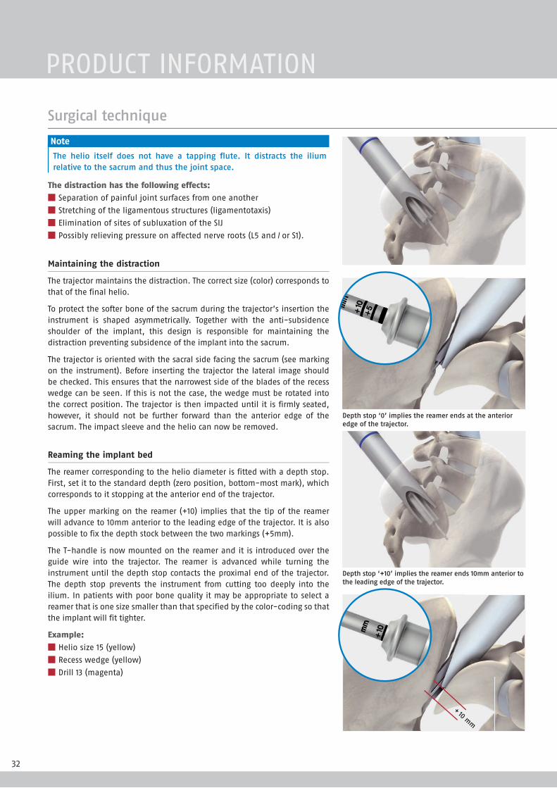
Note
The helio itself does not have a tapping flute. It distracts the ilium relative to the sacrum and thus the joint space.
The distraction has the following effects:
■ Separation of painful joint surfaces from one another
■ Stretching of the ligamentous structures (ligamentotaxis)
■ Elimination of sites of subluxation of the SIJ
■ Possibly relieving pressure on affected nerve roots (L5 and / or S1).
Maintaining the distraction
The trajector maintains the distraction. The correct size (color) corresponds to that of the final helio.
To protect the softer bone of the sacrum during the trajector’s insertion the instrument is shaped asymmetrically. Together with the anti-subsidence shoulder of the implant, this design is responsible for maintaining the distraction preventing subsidence of the implant into the sacrum.
The trajector is oriented with the sacral side facing the sacrum (see marking on the instrument). Before inserting the trajector the lateral image should be checked. This ensures that the narrowest side of the blades of the recess wedge can be seen. If this is not the case, the wedge must be rotated into the correct position. The trajector is then impacted until it is firmly seated, however, it should not be further forward than the anterior edge of the sacrum. The impact sleeve and the helio can now be removed.
Reaming the implant bed
The reamer corresponding to the helio diameter is fitted with a depth stop. First, set it to the standard depth (zero position, bottom-most mark), which corresponds to it stopping at the anterior end of the trajector.
The upper marking on the reamer (+10) implies that the tip of the reamer will advance to 10mm anterior to the leading edge of the trajector. It is also possible to fix the depth stock between the two markings (+5mm).
The T-handle is now mounted on the reamer and it is introduced over the guide wire into the trajector. The reamer is advanced while turning the instrument until the depth stop contacts the proximal end of the trajector. The depth stop prevents the instrument from cutting too deeply into the ilium. In patients with poor bone quality it may be appropriate to select a reamer that is one size smaller than that specified by the color-coding so that the implant will fit tighter.
Example:
■ Helio size 15 (yellow)
■ Recess wedge (yellow)
■ Drill 13 (magenta)
+ 10 mm
Surgical technique
Depth stop ‘0’ implies the reamer ends at the anterior edge of the trajector.
Depth stop ‘+10’ implies the reamer ends 10mm anterior to the leading edge of the trajector.
PRODUCT INFORMATION

33
Final position of the DIANA implant AP. Final position of the DIANA implant oblique. Final position of the DIANA implant lateral.
Surgical technique
4 Implantation and bone transplantation
The implant size corresponding to that of the helio is loaded on its respective color-coded inserter. After attaching the T-handle, the implant is inserted over the guide wire. The implant is advanced under fluoroscopic control (lateral view) until it is seated in the desired position.
The inserter is now withdrawn by pulling back on the T-handle. The guide wire is removed with the battery-powered drill and the trajector is withdrawn with the slap hammer. The implant and the extra-articular space are now carefully filled with bone material. When doing so, ensure that the bone material completely fills the recess distally and proximally as well as the implant itself. Before final closure of the wound, the position of the implant must be checked fluoroscopically in all three planes.
DIANA

34
Data
Date of surgery: MM.DD.YYYY
Patient: First name, last name Date of birth.: MM.DD.YYYY
Surgeon: First name, last name
Assistant: First name, last name
Diagnosis: Primary (M19.05)/secondary SIJ osteoarthritis (M19.25) right/left; secondary diagnoses
Operation: Distraction interference arthrodesis of the sacroiliac joint (DIANA, SIGNUS Medizintechnik GmbH)(5-808.0 Arthrodesis: sacroiliac joint) Size 13/15/17/19 mm
Operation sequence
Sample operative report
The patient is positioned in a prone position. Positioning the fluoroscope in all three planes and determination of the skin incision with the help of a wire under fluoroscopic guidance to define the upper edge of the sacrum. Usual surgical field prepa-ration with disinfection and sterile draping of the surgical area.
The access is opened to the fascia via a midline incision of approximately 5cm length.
The subcutaneous tissue is pushed away from the fascia down to the posterior superior iliac spine (PSIS) and the recess. The fascia is opened up about 1 finger width medial to the PSIS along the fibers. Bluntly force apart of the musculature. Placement of the Cobb elevator on the ilium and sliding in a medial direction into the “soft spot” of the ligamentous apparatus over the posterior recess. At this site, resection of the posterior parts of the sacroiliac ligaments with the rongeur until the recess can be visualized. The recess is then carefully curetted until the joint space can be visualized in readiness for apposition of the bone material.
Using a high-speed drill, several punctate holes 3-5mm in size are drilled in the medial side of the ilium and the lateral side of the sacrum to expose the medullary cavity. The previously prepared homologous cancellous bone is inserted into the prepared recess down to its base and then lightly compacted. The homologous bone graft was also mixed with autologous cancellous bone that was removed from the ilium using a hollow drill. The harvest site in the ilium is filled with cancellous bone.
The direction of the instrument is now determined with the blunt guide wire under fluoroscopic guidance. The guide wire is inserted under fluoroscopic guidance and advanced to the ilium under fluoroscopic guidance.
The guide sleeve is then inserted into the recess via the K wire, the K wire is removed and replaced by the cutting guide wire. The wire is advanced about 2cm into the ilium with the drill. After radiographic verification in three planes (AP, oblique, lateral), the guidance aids are removed.
PRODUCT INFORMATION
35
The smallest (13mm) helio is now inserted via the guide wire and the joint is distracted. After 10 complete rotations (corre-sponds to 3cm advancement), the next larger size is used until the resistance clearly indicates that the helio is firmly seated. In this case this was size XX/XX .
The distal end of the helio is seen at the height of the anterior edge of the sacrum in the lateral radiographic check.
The distraction is maintained with a XX/XX trajector of the same size by advancing the trajector over the helio until it is seated.
The helio is removed, and the trajector and the guide wire remain in place. A reamer of the same size or a smaller size is advanced with the depth stop to a depth of XX/XX .
Removal of the reamer. The XX/XX implant is inserted into the recess via the guide wire using the inserter and rotated to the correct final position.
Removal of the inserter, the guide wire, and the trajector. The radiographic check shows proper seating of the inserted implant. The implant and the rest of the recess are now carefully filled with the remaining cancellous bone. The bone material is compacted solidly and a subfascial drain is placed.
Layered wound closure of fascia, subcutaneous layer, and skin.
Application of a sterile wound dressing.
Postoperative treatment ● Redon drain and indwelling catheter removal on postop-erative day two.
● If necessary, CT and pelvic view, postoperative partial weight bearing on the operated side with 20kg for 8 weeks with underarm crutches.
● Continue with low-molecular-weight heparin throughout partial weight bearing.
Surgeon
Signature
Insertion of a subfascial redon drain, intracutaneous suture/skin staples.
An extensive bipolar denervation of the right SIJ concludes the procedure.
Sample operative report
■ Removal of the redon drain and indwelling catheter on day 2 after surgery.
■ Partial weight bearing of the leg on the treated side with 20kg for eight weeks using underarm crutches.
■ Anti-thrombotic prophylaxis over eight weeks.
■ Vitamin D substitution over three months.
■ Due to possible delayed bone healing, no NSAIDs!
■ Preparation of a pelvic view and, if necessary, postoper-ative CT of the pelvis (checking the position and extent of the deposited homologous bone).
■ No physical therapy!
■ The patient should avoid bending, spreading the legs, and lifting heavy loads for a total of six months.
■ After nine to twelve months, another CT is recommended for radiographic verification of the bony fusion.
Postoperative treatmentThe following steps should be carried out for the follow-up treatment*:
* The indication, selection and implantation lies in the responsibility of the user surgeon and must be individually be adapted to the patient’s needs.
DIANA

36
The following case study reveals the importance of the physical examinations when determining the surgical indication:
Patient: ● 46 years old, female ● Profession: chef ● Lumbar SP symptoms since 2001 ● Regular physical therapy (MT) ● Fall in 1/2010; clear increase in sitting pain symptoms radiating out from the left buttock and upper leg, intermittent in the left calf
● Sitting pain intensifies with sitting and lying on the left side
● Unable to work
Findings: ● Natural gait pattern ● No tenderness to palpation or percussion of the lumbar spine
● Clear tenderness to palpation of the left SI joint, figure four test +, Mennell’s sign + internal rotation sitting pain in left hip joint
● Bilateral straight leg raise, no neurological deficits
● VAS 9.5/10 (back) ● VAS 8/10 (leg) ● Hemisacralization L5 right (!) ● Spondylarthrosis L3–5 accentuated on the left ● Slight fixation of listhesis L3/4
Injection: ● 1st injection into left SI joint recess ➞ 80% SP reduction for 24h
● 2nd injection into recess and 1st injection into SI joint with CA ➞ almost pain free for 36h
7 months post-OP ● Preoperative pain considerably improved ● VAS 3.5/10 (back) ● VAS 0.5/10 (leg) ● After more than 4h work, intermittent, short-lived, stabbing SP
● Pain no longer radiates in the left leg ● Can lie on the left side again ● “Everything is better than before” ● Can work again ● SIJ arthrodesis union in the CT
List of abbreviations
TTP tenderness to palpation
IR internal rotation
CA contrast agent
TTP tenderness to percussion
MT manipulative therapy
SP pain on sitting
CT SIJ pre-OP.
DIANA (19 mm).
CT 6 months.
Case study
Dr. Volker Fuchs M.D., AMEOS Hospital, Halberstadt (Germany)
PRODUCT INFORMATION

37
Pre-OP pain drawing. Post-OP pain drawing.
Injection.
Case study
Numbness = Numbness =Pricking = Pricking =
Taut = Taut =
Burning = Burning =
Stabbing = Stabbing =Painful = Painful =
DIANA

38
Notes
PRODUCT INFORMATION

39
Notes
DIANA

NOTE: This document was written by the technical department at SIGNUS Medizintechnik GmbH. Despite being reviewed by trained personnel, the sole purpose of this brochure is to provide an explanation of the technical aspects of handling the product described. This document, in particular the description of the surgical procedure, should not be considered medical scientific literature.
SIGNUS Medizintechnik GmbH Industriestr. 2 63755 Alzenau/Germany
Tel: +49 (0) 6023 9166 - 0 Fax: +49 (0) 6023 9166 - 161
info@ signus.com www. signus.com
SIGNUS Australia Pty Ltd Suite 12/133 Alexander St. Crows Nest, NSW 2065
Phone: +61 (0) 2 9973-2771 Fax: +61 (0) 02 8088 4766
[email protected] www.signus.com.au
DIPLOMAT®
Thoracolumbar posterior instrumentationAugmentable posterior pedicle screw system
MOBIS® II STTransforaminal Lumbar Interbody Fusion
ASCOT®
Anterior cervical stabilization
TLIF Cage
Cervical Plate System
Rev.
201
5-09
/ 0
2